EP1513374B1 - Wärmelade - Google Patents
Wärmelade Download PDFInfo
- Publication number
- EP1513374B1 EP1513374B1 EP04014195A EP04014195A EP1513374B1 EP 1513374 B1 EP1513374 B1 EP 1513374B1 EP 04014195 A EP04014195 A EP 04014195A EP 04014195 A EP04014195 A EP 04014195A EP 1513374 B1 EP1513374 B1 EP 1513374B1
- Authority
- EP
- European Patent Office
- Prior art keywords
- drawer
- housing
- plate
- electronics
- accordance
- Prior art date
- Legal status (The legal status is an assumption and is not a legal conclusion. Google has not performed a legal analysis and makes no representation as to the accuracy of the status listed.)
- Expired - Lifetime
Links
- 238000010438 heat treatment Methods 0.000 title description 9
- 239000004020 conductor Substances 0.000 claims description 8
- 230000008878 coupling Effects 0.000 claims description 7
- 238000010168 coupling process Methods 0.000 claims description 7
- 238000005859 coupling reaction Methods 0.000 claims description 7
- 230000001105 regulatory effect Effects 0.000 claims description 3
- 238000010792 warming Methods 0.000 claims 7
- 239000011521 glass Substances 0.000 description 5
- 238000011161 development Methods 0.000 description 2
- 230000018109 developmental process Effects 0.000 description 2
- 230000003014 reinforcing effect Effects 0.000 description 2
- 230000000694 effects Effects 0.000 description 1
- 239000000463 material Substances 0.000 description 1
- 238000000034 method Methods 0.000 description 1
Images


Classifications
-
- H—ELECTRICITY
- H05—ELECTRIC TECHNIQUES NOT OTHERWISE PROVIDED FOR
- H05B—ELECTRIC HEATING; ELECTRIC LIGHT SOURCES NOT OTHERWISE PROVIDED FOR; CIRCUIT ARRANGEMENTS FOR ELECTRIC LIGHT SOURCES, IN GENERAL
- H05B3/00—Ohmic-resistance heating
- H05B3/68—Heating arrangements specially adapted for cooking plates or analogous hot-plates
- H05B3/686—Heat-storage plates
-
- A—HUMAN NECESSITIES
- A47—FURNITURE; DOMESTIC ARTICLES OR APPLIANCES; COFFEE MILLS; SPICE MILLS; SUCTION CLEANERS IN GENERAL
- A47J—KITCHEN EQUIPMENT; COFFEE MILLS; SPICE MILLS; APPARATUS FOR MAKING BEVERAGES
- A47J39/00—Heat-insulated warming chambers; Cupboards with heating arrangements for warming kitchen utensils
- A47J39/006—Heat-insulated warming chambers; Cupboards with heating arrangements for warming kitchen utensils for either storing and preparing or for preparing food on serving trays, e.g. heating, thawing, preserving
-
- A—HUMAN NECESSITIES
- A47—FURNITURE; DOMESTIC ARTICLES OR APPLIANCES; COFFEE MILLS; SPICE MILLS; SUCTION CLEANERS IN GENERAL
- A47J—KITCHEN EQUIPMENT; COFFEE MILLS; SPICE MILLS; APPARATUS FOR MAKING BEVERAGES
- A47J39/00—Heat-insulated warming chambers; Cupboards with heating arrangements for warming kitchen utensils
- A47J39/02—Dish-warmers; Devices to keep food hot
Definitions
- the invention relates to a heat load with a housing in which a drawer is guided displaceably.
- the heat load can be used as a separate device. However, it is also suitable for use in combination with other devices, devices or devices, in particular with electrical appliances.
- the task is to warm or keep food and / or dishes warm.
- the DE 30 15 286 A1 discloses a baking and / or roasting device with a heat load according to the preamble of claim 1.
- the object of the invention is to propose an improved heat load of the type specified.
- the drawer has a heatable plate.
- the food and / or the dishes can be placed on the heatable plate. You can get warmed up there and / or kept warm.
- the heat load is characterized in that plate is provided under the heatable plate a reflector. As a result, the efficiency can be improved.
- the heatable plate has conductor tracks.
- the tracks serve to electrically heat the plate.
- they are printed printed conductors.
- the heatable plate is preferably made of glass.
- a current coupling is provided, which serves to supply the conductor tracks with electrical energy.
- the power coupling is preferably provided on the rear wall of the drawer and on the rear wall of the housing.
- an electronics housing may be provided.
- the electronics housing is preferably fixedly connected to the housing.
- electronics in particular a control and / or control electronics, housed.
- the heat load comprises an additional heating.
- the additional heater is preferably arranged in the housing.
- the additional heater comprises a fan.
- This can be a cross-flow fan.
- a further advantageous development is characterized by an electronics for regulating the temperature by regulating the resistance of the heatable plate. This is particularly advantageous if the heatable plate has printed conductors, which are preferably printed.
- the heat load 1 comprises a housing 2, in which a drawer 3 is guided displaceably.
- the housing 2 is designed as a built-in housing. It comprises side walls 4, 5, of which on the front side mounting lugs 6, 7 project at right angles to the outside, in which mounting holes are provided, which are penetrated by mounting screws, a rear wall 8, a lower housing wall 9 and an upper housing wall 10th
- the drawer 3 comprises a front panel 11 with a handle 12, side reinforcing bars 13, 14, which have guides which are slidably guided in corresponding guides in the housing 2, a rear cross bar 15 and a bottom 16 and a heatable plate 17 made of glass.
- the plate 17 is at its edges in the Fig. 4 apparent manner from the edge of the bottom 16 and a flange 18 of the reinforcing bars 13, 14 bordered.
- the bottom 16 has, following its edge 19, a downwardly directed bend 20, so that it extends at a distance a from the plate 17. As a result, the bottom 16 forms a reflector plate for the plate 17th
- the conductor 21 extends in the Fig. 2 apparently meandering.
- a current coupling is provided, which cooperates with a current coupling in the region of the rear wall 8 of the housing 2.
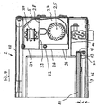
- an electronics housing 22 is provided, which is connected in the upper right corner of the housing 2 with the upper housing wall 10 and the right side wall 5 of the housing 2.
- a warning light 23 and a rotary switch 24 are present on the front panel of the electronics housing 22 .
- the electronics present in the electronics housing 22 regulate the temperature of the heater. The operator can set a setpoint of the temperature between seven different stages.
- auxiliary heater comprises a cross-flow fan 25, through which air is sucked through the intake slots 26 in the electronics housing 22.
- the air is passed through an air guide 27 and an opening 28 in an intermediate floor 29 to a heating coil 30, from which it is warmed up.
- the warmed air leaves the electronics housing 22 through air outlet slots 31st
- the existing electronics in the electronics housing 22 switches the additional heating when needed. Furthermore, the electronics cause a boil, so a steep rise in temperature. It then adjusts the temperature to the set setpoint.
- the electronics indicate whether the drawer is closed or not closed, for example by the indicator light flashing when the drawer is not closed and lit continuously when the drawer is closed. The electronics finally indicate whether there is a fault on the device.
- the housing 2 includes the full extension of the drawer 3 with self-closing.
- the electronics which is located in the electronics housing 22, integrated. When the device is closed, only the warning light (signal lamp) 23 can be seen.
- the additional heater is automatically switched on.
- the auxiliary heater generates a circulation of the air in the drawer 3.
- the air is heated by the heating coil 30.
- the heating of the plate 17 has a PTC characteristic. This means that with increasing temperature of the plate 17 and the electrical resistance of the heater increases.
- the resistivity of the plate is in the embodiment at 0.4 ohms / K. This effect is exploited in the control, so that the controller performs a temperature control by a resistance control.
- the plate 17 has at RT20 a certain resistance x, which is read into the factory control once.
- the controller adjusts the resistance to the setpoint, which sets the temperature to the temperature corresponding to this resistance.
- the arrangement is such that the plate 17 is heated only when the drawer 3 is completely closed.
- corresponding sensors may be provided.
- the duration of preheating depends on the material and thickness of the crockery, the quantity of crockery, the height and the arrangement of the crockery.
- the dishes are placed in the drawer 3, so put on the plate 17. Then the rotary switch is set to level 3.
- the drawer 3 is closed.
- the preheating process is carried out for 10 minutes. Subsequently, the drawer 3 is opened.
- the food is placed in the preheated crockery. Then the drawer is closed again.
- the control lamp lights up continuously.
- the device is heating.
Landscapes
- Engineering & Computer Science (AREA)
- Food Science & Technology (AREA)
- Devices For Warming Or Keeping Food Or Tableware Hot (AREA)
- Baking, Grill, Roasting (AREA)
- Electric Stoves And Ranges (AREA)
Description
- Die Erfindung betrifft eine Wärmelade mit einem Gehäuse, in dem eine Schublade verschieblich geführt ist.
- Die Wärmelade kann als gesondertes Gerät verwendet werden. Sie eignet sich allerdings auch zur Verwendung in Kombination mit anderen Geräten, Vorrichtungen oder Einrichtungen, insbesondere mit Elektrogeräten.
- In der Küche, und zwar sowohl im privaten Haushalt als auch in einer gewerblichen Küche, stellt sich die Aufgabe, Speisen und/oder Geschirr zu wärmen oder warmzuhalten.
- Aus der
US-A-2 535 379 ist eine Wärmelade nach dem Oberbegriff des Anspruchs 1 bekannt. - Die
DE 30 15 286 A1 offenbart eine Back- und/oder Brateinrichtung mit einer Wärmelade nach dem Oberbegriff des Anspruchs 1. - Aufgabe der Erfindung ist es, eine verbesserte Wärmelade der eingangs angegebenen Art vorzuschlagen.
- Erfindungsgemäß wird diese Aufgabe durch die Merkmale des Anspruchs 1 gelöst. Die Schublade weist eine beheizbare Platte auf. Die Speisen und/oder das Geschirr können auf die beheizbare Platte gestellt werden. Sie können dort gewärmt und/oder warmgehalten werden. Die Wärmelade ist dadurch gekennzeichnet, daß unter der beheizbaren Platte eine Reflektor platte vorgesehen ist. Hierdurch kann der Wirkungsgrad verbessert werden.
- Vorteithafte Weiterbildungen sind in den Unteransprüchen beschrieben.
- Vorteilhaft ist es, wenn die beheizbare Platte Leiterbahnen aufweist. Die Leiterbahnen dienen zur elektrischen Beheizung der Platte. Vorzugsweise handelt es sich um aufgedruckte Leiterbahnen.
- Die beheizbare Platte ist vorzugsweise aus Glas.
- Nach einer weiteren vorteilhaften Weiterbildung ist eine Stromkupplung vorgesehen, die dazu dient, die Leiterbahnen mit elektrischer Energie zu versorgen. Die Stromkupplung ist vorzugsweise an der Rückwand der Schublade und an der Rückwand des Gehäuses vorgesehen.
- In dem Gehäuse kann ein Elektronikgehäuse vorgesehen sein. Das Elektronikgehäuse ist vorzugsweise fest mit dem Gehäuse verbunden. In dem Elektronikgehäuse kann eine Elektronik, insbesondere eine Steuer- und/oder Regelelektronik, untergebracht sein.
- Vorteilhaft ist es, wenn die Wärmelade eine Zusatzheizung umfaßt. Die Zusatzheizung ist vorzugsweise im Gehäuse angeordnet.
- Vorzugsweise umfaßt die Zusatzheizung ein Gebläse. Dabei kann es sich um ein Querstromgebläse handeln.
- Eine weitere vorteilhafte Weiterbildung ist gekennzeichnet durch eine Elektronik zum Regeln der Temperatur durch eine Regelung des Widerstands der beheizbaren Platte. Dies ist insbesondere dann vorteilhaft, wenn die beheizbare Platte Leiterbahnen, die vorzugsweise aufgedruckt sind, aufweist.
- Ein Ausführungsbeispiel der Erfindung wird nachstehend anhand der beigefügten Zeichnung im einzelnen erläutert. In der Zeichnung zeigt
- Fig. 1
- eine Wärmelade mit herausgezogener Schublade in einer perspektivischen Ansicht,
- Fig. 2
- die in
Fig. 1 dargestellte Schublade in einer Ansicht von oben, - Fig. 3
- das in
Fig. 1 dargestellte Gehäuse in einer Ansicht von vorne und - Fig. 4
- eine Zusatzheizung in einem Querschnitt.
- Die Wärmelade 1 umfaßt ein Gehäuse 2, in dem eine Schublade 3 verschieblich geführt ist.
- Das Gehäuse 2 ist als Einbaugehäuse ausgestaltet. Es umfaßt Seitenwände 4, 5, von denen an der Frontseite Einbaulaschen 6, 7 rechtwinklig nach außen abstehen, in denen Montagelöcher vorgesehen sind, die von Montageschrauben durchgriffen werden, eine hintere Wand 8, eine untere Gehäusewand 9 und eine obere Gehäusewand 10.
- Die Schublade 3 umfaßt eine Frontplatte 11 mit einem Griff 12, seitliche Verstärkungsleisten 13, 14, die Führungen aufweisen, die in entsprechenden Führungen in dem Gehäuse 2 verschieblich geführt sind, eine hintere Querleiste 15 und einen Boden 16 und eine beheizbare Platte 17 aus Glas. Die Platte 17 ist an ihren Rändern in der aus
Fig. 4 ersichtlichen Weise vom Rand des Bodens 16 und einem Flansch 18 der Verstärkungsleisten 13, 14 eingefaßt. Der Boden 16 weist im Anschluß an seinen Rand 19 eine nach unten gerichtete Abkröpfung 20 auf, so daß er im Abstand a von der Platte 17 verläuft. Hierdurch bildet der Boden 16 eine Reflektorplatte für die Platte 17. - Auf die beheizbare Platte 17 aus Glas sind Leiterbahnen 21 aufgedruckt. Die Leiterbahn 21 verläuft in der aus
Fig. 2 ersichtlichen Weise meanderförmig. - Im Bereich der hinteren Querleiste 15 ist eine Stromkupplung vorgesehen, die mit einer Stromkupplung im Bereich der hinteren Wand 8 des Gehäuses 2 zusammenwirkt.
- In dem Gehäuse 2 ist ein Elektronikgehäuse 22 vorgesehen, das in der rechten oberen Ecke des Gehäuses 2 mit der oberen Gehäusewand 10 und der rechten Seitenwand 5 des Gehäuses 2 verbunden ist. An der Frontplatte des Elektronikgehäuses 22 sind eine Kontrollleuchte 23 und ein Drehschalter 24 vorhanden. Die in dem Elektronikgehäuse 22 vorhandene Elektronik regelt die Temperatur der Heizung. Der Bediener kann zwischen sieben verschiedenen Stufen einen Sollwert der Temperatur einstellen.
- In dem Elektronikgehäuse 22 ist ferner eine Zusatzheizung vorhanden, die in
Fig. 4 im Querschnitt dargestellt ist. Die Zusatzheizung umfaßt ein Querstromgebläse 25, durch welches Luft durch die Ansaugschlitze 26 im Elektronikgehäuse 22 angesaugt wird. Die Luft wird durch eine Luftführung 27 und einen Durchbruch 28 in einem Zwischenboden 29 zu einer Heizwendel 30 geleitet, von der sie aufgewärmt wird. Die aufgewärmte Luft verläßt das Elektronikgehäuse 22 durch Luftaustrittsschlitze 31. - Die in dem Elektronikgehäuse 22 vorhandene Elektronik schaltet die Zusatzheizung bei Bedarf zu. Ferner bewirkt die Elektronik ein Ankochen, also einen steilen Temperaturanstieg. Sie regelt die Temperatur dann auf den eingestellten Sollwert ein. Die Elektronik zeigt an, ob die Schublade geschlossen oder nicht geschlossen ist, beispielsweise dadurch, daß die Kontrollleuchte bei nicht geschlossener Schublade blinkt und nach dem Schließen der Schublade durchgehend leuchtet. Die Elektronik zeigt schließlich noch an, ob an dem Gerät eine Störung vorhanden ist.
- Das Gehäuse 2 beinhaltet die Vollauszüge für die Schublade 3 mit Selbsteinzug. Zudem ist in dem Gehäuse 2 die Elektronik, die sich im Elektronikgehäuse 22 befindet, integriert. Bei geschlossenem Gerät ist nur die Kontrollleuchte (Signallampe) 23 erkennbar.
- Wenn die Leiterbahnen 21, die auf die Unterseite der Glasplatte 17 aufgedruckt sind, von Strom durchflossen werden, erwärmt sich das Glas der Platte 17. Die Energiezufuhr erfolgt über eine Stromkupplung, die sich auf der Rückwand des Gehäuses und auf der Rückwand der Schublade befindet. Bei geschlossener Schublade wird der Stromkreis über die Stromkupplung geschlossen, und zwar nach dem Prinzip des Cordless-Wasserkochers.
- Wenn sich der Drehschalter 23 in der Schaltstellung 32, also in der Stufe "Tellerwärmen", befindet, wird die Zusatzheizung automatisch zugeschaltet. Die Zusatzheizung erzeugt eine Zirkulation der Luft in der Schublade 3. Zusätzlich wird die Luft durch die Heizwendel 30 erwärmt.
- Die Heizung der Platte 17 besitzt eine PTC-Charakteristik. Dies bedeutet, daß bei zunehmender Temperatur der Platte 17 auch der elektrische Widerstand der Heizung ansteigt. Der spezifische Widerstand der Platte liegt beim Ausführungsbeispiel bei 0,4 Ohm/K. Dieser Effekt wird bei der Regelung ausgenutzt, so daß die Steuerung eine Temperaturregelung durch eine Widerstandsregelung durchführt. Die Platte 17 hat bei RT20 einen bestimmten Widerstand x, der in die Steuerung werkseitig einmal eingelesen wird. Die Steuerung regelt den Widerstand auf den eingestellten Sollwert ein, wodurch die Temperatur auf die diesem Widerstandswert entsprechende Temperatur eingestellt wird. Der Widerstandswert wird nach folgender Funktion berechnet: R = x + (4*n), wobei n die Schaltstufe und R den Widerstand bedeuten. Dies ergibt ein maximales Widerstandsdelta von 28 Ohm. Thermisch gesehen bedeutet dies ein Temperaturdelta von 70° K. Im Ergebnis wird auf diese Weise über den Widerstand die Temperatur geregelt.
- Die Anordnung ist derart getroffen, daß die Platte 17 nur dann beheizt wird, wenn die Schublade 3 vollständig geschlossen ist. Hierzu können entsprechende Sensoren vorgesehen sein.
- Zum Betrieb der Wärmelade in der Betriebsart "Geschirr vorwärmen" wird zunächst Geschirr in die Schublade 3 geräumt, also auf die Platte 17 gestellt. Der Drehschalter 24 wird auf die Stellung 32 gestellt. Die Kontrollleuchte 23 blinkt. Nach dem Schließen der Schublade 3 leuchtet die Kontrollleuchte 23 durchgehend. Das Gerät heizt.
- Die Dauer des Vorwärmens richtet sich nach Material und Dicke des Geschirrs, der Geschirr-Menge, der Höhe und der Anordnung des Geschirrs.
- Zum Betrieb der Wärmelade in der Betriebsart "Speisen warmhalten" wird das Geschirr in die Schublade 3 gestellt, also auf die Platte 17 gestellt. Anschließend wird der Drehschalter auf die Stufe 3 gestellt. Die Schublade 3 wird geschlossen. Der Vorheizvorgang wird für 10 Minuten durchgeführt. Anschließend wird die Schublade 3 geöffnet. Die Speisen werden in das vorgewärmte Geschirr gegeben. Anschließend wird die Schublade wieder geschlossen. Die Kontrolleuchte leuchtet durchgehend. Das Gerät heizt.
Claims (7)
- Wärmelade mit einem Gehäuse (2), in dem eine Schublade (3) verschieblich geführt ist, wobei
die Schublade (3) eine beheizbare Platte (17) aufweist, dadurch gekennzeichnet, daß unter der beheizbaren Platte (17) eine Reflektorplatte (16) vorgesehen ist. - Wärmelade nach Anspruch 1, dadurch gekennzeichnet, daß die beheizbare Platte (17) Leiterbahnen (21) aufweist.
- Wärmelade nach Anspruch 2, gekennzeichnet durch eine Stromkupplung an der Schublade (3) und an dem Gehäuse (2).
- Wärmelade nach einem der vorhergehenden Ansprüche, dadurch gekennzeichnet, daß in dem Gehäuse (2) ein Elektronikgehäuse (22) vorgesehen ist.
- Wärmelade nach einem der vorhergehenden Ansprüche, gekennzeichnet durch eine Zusatzheizung.
- Wärmelade nach Anspruch 5, dadurch gekennzeichnet, daß die Zusatzheizung ein Gebläse (25) umfaßt.
- Wärmelade nach einem der vorhergehenden Ansprüche, gekennzeichnet durch eine Elektronik zum Regeln der Temperatur durch eine Regelung des Widerstands der beheizbaren Platte (17).
Priority Applications (4)
| Application Number | Priority Date | Filing Date | Title |
|---|---|---|---|
| EP10007583.7A EP2237640B1 (de) | 2003-09-02 | 2004-06-17 | Wärmelade |
| PL04014195T PL1513374T3 (pl) | 2003-09-02 | 2004-06-17 | Lada grzewcza |
| PL10007583T PL2237640T3 (pl) | 2003-09-02 | 2004-06-17 | Lada grzewcza |
| SI200431614T SI1513374T1 (sl) | 2003-09-02 | 2004-06-17 | Ogrevalni predal |
Applications Claiming Priority (4)
| Application Number | Priority Date | Filing Date | Title |
|---|---|---|---|
| DE20313616 | 2003-09-02 | ||
| DE20313616U | 2003-09-02 | ||
| DE20316141U | 2003-10-21 | ||
| DE20316141U DE20316141U1 (de) | 2003-09-02 | 2003-10-21 | Wärmelade |
Related Child Applications (2)
| Application Number | Title | Priority Date | Filing Date |
|---|---|---|---|
| EP10007583.7A Division EP2237640B1 (de) | 2003-09-02 | 2004-06-17 | Wärmelade |
| EP10007583.7 Division-Into | 2010-07-21 |
Publications (3)
| Publication Number | Publication Date |
|---|---|
| EP1513374A2 EP1513374A2 (de) | 2005-03-09 |
| EP1513374A3 EP1513374A3 (de) | 2007-10-03 |
| EP1513374B1 true EP1513374B1 (de) | 2010-12-22 |
Family
ID=34137349
Family Applications (1)
| Application Number | Title | Priority Date | Filing Date |
|---|---|---|---|
| EP04014195A Expired - Lifetime EP1513374B1 (de) | 2003-09-02 | 2004-06-17 | Wärmelade |
Country Status (2)
| Country | Link |
|---|---|
| EP (1) | EP1513374B1 (de) |
| PL (1) | PL1513374T3 (de) |
Cited By (4)
| Publication number | Priority date | Publication date | Assignee | Title |
|---|---|---|---|---|
| DE202013001632U1 (de) | 2013-02-19 | 2014-05-20 | Michatek, K.S. | Wärmelade |
| DE102015002981A1 (de) | 2014-09-01 | 2016-03-03 | Michatek, K.S. | Schublade für ein Möbel oder für ein Gerät |
| DE102015002993A1 (de) | 2014-09-01 | 2016-03-03 | Michatek, K.S. | Front für ein Möbel oder Gerät |
| DE102015002980A1 (de) | 2014-09-01 | 2016-03-03 | Michatek, K.S. | Front für ein Möbel oder für ein Gerät |
Families Citing this family (6)
| Publication number | Priority date | Publication date | Assignee | Title |
|---|---|---|---|---|
| FR2963546B1 (fr) * | 2010-08-05 | 2012-08-03 | Illinois Tool Works | Appareil de chauffe du type etuve |
| DE202010014909U1 (de) | 2010-10-29 | 2012-01-30 | Gronbach Forschungs- Und Entwicklungs Gmbh & Co. Kg | Wärmeschublade |
| DE202010014908U1 (de) | 2010-10-29 | 2012-01-30 | Gronbach Forschungs- Und Entwicklungs Gmbh & Co. Kg | Wärmeschublade |
| DE102010054322B4 (de) | 2010-12-13 | 2022-01-27 | Gronbach Forschungs- Und Entwicklungs Gmbh & Co. Kg | Wärmeschublade |
| DE102011101042A1 (de) * | 2011-05-10 | 2012-11-15 | Gronbach Forschungs- Und Entwicklungs Gmbh & Co. Kg | Gargerät |
| AU2015228404A1 (en) * | 2014-03-13 | 2016-10-27 | Lino ALIOLI | Heat conditioning device underneath a shelf and catering table thereof |
Family Cites Families (5)
| Publication number | Priority date | Publication date | Assignee | Title |
|---|---|---|---|---|
| US2535379A (en) * | 1944-12-30 | 1950-12-26 | Mullins Mfg Corp | Electric cooking unit |
| US3146338A (en) * | 1962-01-02 | 1964-08-25 | Gen Electric | Electric oven |
| AT371688B (de) * | 1979-05-11 | 1983-07-25 | Elektra Bregenz Gmbh | Back- und/oder brateinrichtung |
| US4904848A (en) * | 1989-02-08 | 1990-02-27 | Geraldean Colevas | Portable cooling and heating device |
| US6265695B1 (en) * | 1997-01-31 | 2001-07-24 | Benno Liebermann | Food thermalization device and method |
-
2004
- 2004-06-17 EP EP04014195A patent/EP1513374B1/de not_active Expired - Lifetime
- 2004-06-17 PL PL04014195T patent/PL1513374T3/pl unknown
Cited By (5)
| Publication number | Priority date | Publication date | Assignee | Title |
|---|---|---|---|---|
| DE202013001632U1 (de) | 2013-02-19 | 2014-05-20 | Michatek, K.S. | Wärmelade |
| DE102015002981A1 (de) | 2014-09-01 | 2016-03-03 | Michatek, K.S. | Schublade für ein Möbel oder für ein Gerät |
| DE102015002993A1 (de) | 2014-09-01 | 2016-03-03 | Michatek, K.S. | Front für ein Möbel oder Gerät |
| DE102015002980A1 (de) | 2014-09-01 | 2016-03-03 | Michatek, K.S. | Front für ein Möbel oder für ein Gerät |
| DE102015002993B4 (de) | 2014-09-01 | 2022-06-30 | Gronbach K.S. | Front für ein Möbel oder Gerät |
Also Published As
| Publication number | Publication date |
|---|---|
| EP1513374A2 (de) | 2005-03-09 |
| PL1513374T3 (pl) | 2011-05-31 |
| EP1513374A3 (de) | 2007-10-03 |
Similar Documents
| Publication | Publication Date | Title |
|---|---|---|
| DE69434248T2 (de) | Garraum mit einer Gebläseschutzvorrichtung | |
| DE60117942T2 (de) | Kochheizung | |
| DE3008689C2 (de) | Durch Mikrowellen und durch elektrische Widerstandsheizung beheizbarer Herd | |
| EP1513374B1 (de) | Wärmelade | |
| DE3228220A1 (de) | Grilleinrichtung | |
| DE3532820A1 (de) | Vorrichtung zum gleichmaessigen erwaermen von raeumen | |
| DE3211487C2 (de) | Kombinationsbackofen | |
| EP2237640B1 (de) | Wärmelade | |
| DE2310867A1 (de) | Regler fuer elektrokochplatten | |
| DE19652130A1 (de) | Elektrischer Durchlauferhitzer | |
| DE102004059822B4 (de) | Verfahren zum Betrieb eines Induktionskochfelds | |
| DE102004042827A1 (de) | Backofen sowie Verfahren zum Betrieb desselben | |
| EP3250002A1 (de) | Haushalts-gargerät | |
| DE69505018T2 (de) | Lüftungsanlage für Kochplatte und dgl. | |
| EP3249302B1 (de) | Haushalts-gargerät | |
| DE69614647T2 (de) | Elektrischer Strahlungsheizkörper und Verfahren zu dessen Betrieb | |
| DE3518124A1 (de) | Elektrokochgeraet | |
| DE29903817U1 (de) | Radiator-Konvektor-Einheit | |
| DE102007050341A1 (de) | Induktionsmodul, Anordnung mehrerer Induktionsmodule und Verfahren zur Einrichtung eines solchen Induktionsmoduls | |
| EP3250001B1 (de) | Haushalts-gargerät | |
| DE2715768C2 (de) | Betriebsschaltung für eine Haushaltskocheinrichtung | |
| EP3210508B1 (de) | Elektrischer grill | |
| EP1217305A1 (de) | Gerätesteuerung für Haushaltsgeräte | |
| EP1791395A2 (de) | Temperaturerfassungseinrichtung für eine Heizeinrichtung sowie Verfahren zur Ansteuerung einer Heizeinrichtung | |
| DE3009190A1 (de) | Elektrisches haarpflegegereaet mit geblaese und heizung |
Legal Events
| Date | Code | Title | Description |
|---|---|---|---|
| PUAI | Public reference made under article 153(3) epc to a published international application that has entered the european phase |
Free format text: ORIGINAL CODE: 0009012 |
|
| AK | Designated contracting states |
Kind code of ref document: A2 Designated state(s): AT BE BG CH CY CZ DE DK EE ES FI FR GB GR HU IE IT LI LU MC NL PL PT RO SE SI SK TR |
|
| AX | Request for extension of the european patent |
Extension state: AL HR LT LV MK |
|
| PUAL | Search report despatched |
Free format text: ORIGINAL CODE: 0009013 |
|
| AK | Designated contracting states |
Kind code of ref document: A3 Designated state(s): AT BE BG CH CY CZ DE DK EE ES FI FR GB GR HU IE IT LI LU MC NL PL PT RO SE SI SK TR |
|
| AX | Request for extension of the european patent |
Extension state: AL HR LT LV MK |
|
| 17P | Request for examination filed |
Effective date: 20071030 |
|
| 17Q | First examination report despatched |
Effective date: 20071213 |
|
| AKX | Designation fees paid |
Designated state(s): AT BE BG CH CY CZ DE DK EE ES FI FR GB GR HU IE IT LI LU MC NL PL PT RO SE SI SK TR |
|
| GRAP | Despatch of communication of intention to grant a patent |
Free format text: ORIGINAL CODE: EPIDOSNIGR1 |
|
| GRAS | Grant fee paid |
Free format text: ORIGINAL CODE: EPIDOSNIGR3 |
|
| GRAA | (expected) grant |
Free format text: ORIGINAL CODE: 0009210 |
|
| AK | Designated contracting states |
Kind code of ref document: B1 Designated state(s): AT BE BG CH CY CZ DE DK EE ES FI FR GB GR HU IE IT LI LU MC NL PL PT RO SE SI SK TR |
|
| REG | Reference to a national code |
Ref country code: GB Ref legal event code: FG4D Free format text: NOT ENGLISH |
|
| REG | Reference to a national code |
Ref country code: CH Ref legal event code: EP Ref country code: CH Ref legal event code: NV Representative=s name: BOVARD AG PATENTANWAELTE |
|
| REG | Reference to a national code |
Ref country code: IE Ref legal event code: FG4D |
|
| REG | Reference to a national code |
Ref country code: PT Ref legal event code: SC4A Free format text: AVAILABILITY OF NATIONAL TRANSLATION Effective date: 20110124 |
|
| REF | Corresponds to: |
Ref document number: 502004012020 Country of ref document: DE Date of ref document: 20110203 Kind code of ref document: P |
|
| REG | Reference to a national code |
Ref country code: DE Ref legal event code: R096 Ref document number: 502004012020 Country of ref document: DE Effective date: 20110203 |
|
| REG | Reference to a national code |
Ref country code: RO Ref legal event code: EPE |
|
| REG | Reference to a national code |
Ref country code: NL Ref legal event code: T3 |
|
| REG | Reference to a national code |
Ref country code: CH Ref legal event code: PFA Owner name: WILHELM GRONBACH GMBH & CO. KG Free format text: WILHELM GRONBACH GMBH & CO. KG#PROF. DR. A. KATREIN-STRASSE 2#6342 NIEDERNDORF (AT) -TRANSFER TO- WILHELM GRONBACH GMBH & CO. KG#PROF. DR. A. KATREIN-STRASSE 2#6342 NIEDERNDORF (AT) |
|
| REG | Reference to a national code |
Ref country code: SE Ref legal event code: TRGR |
|
| REG | Reference to a national code |
Ref country code: ES Ref legal event code: FG2A Ref document number: 2357350 Country of ref document: ES Kind code of ref document: T3 Effective date: 20110425 |
|
| REG | Reference to a national code |
Ref country code: GR Ref legal event code: EP Ref document number: 20110400674 Country of ref document: GR Effective date: 20110412 |
|
| PG25 | Lapsed in a contracting state [announced via postgrant information from national office to epo] |
Ref country code: CY Free format text: LAPSE BECAUSE OF FAILURE TO SUBMIT A TRANSLATION OF THE DESCRIPTION OR TO PAY THE FEE WITHIN THE PRESCRIBED TIME-LIMIT Effective date: 20101222 Ref country code: FI Free format text: LAPSE BECAUSE OF FAILURE TO SUBMIT A TRANSLATION OF THE DESCRIPTION OR TO PAY THE FEE WITHIN THE PRESCRIBED TIME-LIMIT Effective date: 20101222 |
|
| REG | Reference to a national code |
Ref country code: SK Ref legal event code: T3 Ref document number: E 8974 Country of ref document: SK |
|
| REG | Reference to a national code |
Ref country code: HU Ref legal event code: AG4A Ref document number: E010319 Country of ref document: HU |
|
| REG | Reference to a national code |
Ref country code: IE Ref legal event code: FD4D |
|
| PG25 | Lapsed in a contracting state [announced via postgrant information from national office to epo] |
Ref country code: EE Free format text: LAPSE BECAUSE OF FAILURE TO SUBMIT A TRANSLATION OF THE DESCRIPTION OR TO PAY THE FEE WITHIN THE PRESCRIBED TIME-LIMIT Effective date: 20101222 |
|
| PLBE | No opposition filed within time limit |
Free format text: ORIGINAL CODE: 0009261 |
|
| STAA | Information on the status of an ep patent application or granted ep patent |
Free format text: STATUS: NO OPPOSITION FILED WITHIN TIME LIMIT |
|
| PG25 | Lapsed in a contracting state [announced via postgrant information from national office to epo] |
Ref country code: IE Free format text: LAPSE BECAUSE OF FAILURE TO SUBMIT A TRANSLATION OF THE DESCRIPTION OR TO PAY THE FEE WITHIN THE PRESCRIBED TIME-LIMIT Effective date: 20101222 Ref country code: DK Free format text: LAPSE BECAUSE OF FAILURE TO SUBMIT A TRANSLATION OF THE DESCRIPTION OR TO PAY THE FEE WITHIN THE PRESCRIBED TIME-LIMIT Effective date: 20101222 |
|
| 26N | No opposition filed |
Effective date: 20110923 |
|
| REG | Reference to a national code |
Ref country code: DE Ref legal event code: R097 Ref document number: 502004012020 Country of ref document: DE Effective date: 20110923 |
|
| PGFP | Annual fee paid to national office [announced via postgrant information from national office to epo] |
Ref country code: CZ Payment date: 20120529 Year of fee payment: 9 Ref country code: NL Payment date: 20120629 Year of fee payment: 9 Ref country code: SK Payment date: 20120528 Year of fee payment: 9 Ref country code: HU Payment date: 20120611 Year of fee payment: 9 Ref country code: BG Payment date: 20120629 Year of fee payment: 9 |
|
| PGFP | Annual fee paid to national office [announced via postgrant information from national office to epo] |
Ref country code: GR Payment date: 20120627 Year of fee payment: 9 Ref country code: RO Payment date: 20120531 Year of fee payment: 9 Ref country code: PL Payment date: 20120528 Year of fee payment: 9 Ref country code: FR Payment date: 20120704 Year of fee payment: 9 Ref country code: SE Payment date: 20120627 Year of fee payment: 9 |
|
| PGFP | Annual fee paid to national office [announced via postgrant information from national office to epo] |
Ref country code: IT Payment date: 20120620 Year of fee payment: 9 |
|
| PGFP | Annual fee paid to national office [announced via postgrant information from national office to epo] |
Ref country code: BE Payment date: 20120627 Year of fee payment: 9 Ref country code: SI Payment date: 20120528 Year of fee payment: 9 |
|
| PGFP | Annual fee paid to national office [announced via postgrant information from national office to epo] |
Ref country code: ES Payment date: 20120625 Year of fee payment: 9 |
|
| PGFP | Annual fee paid to national office [announced via postgrant information from national office to epo] |
Ref country code: PT Payment date: 20120525 Year of fee payment: 9 |
|
| PG25 | Lapsed in a contracting state [announced via postgrant information from national office to epo] |
Ref country code: MC Free format text: LAPSE BECAUSE OF NON-PAYMENT OF DUE FEES Effective date: 20110630 |
|
| PG25 | Lapsed in a contracting state [announced via postgrant information from national office to epo] |
Ref country code: LU Free format text: LAPSE BECAUSE OF NON-PAYMENT OF DUE FEES Effective date: 20110617 |
|
| REG | Reference to a national code |
Ref country code: PT Ref legal event code: MM4A Free format text: LAPSE DUE TO NON-PAYMENT OF FEES Effective date: 20131217 |
|
| BERE | Be: lapsed |
Owner name: WILHELM GRONBACH GMBH & CO. KG Effective date: 20130630 |
|
| REG | Reference to a national code |
Ref country code: NL Ref legal event code: V1 Effective date: 20140101 |
|
| PG25 | Lapsed in a contracting state [announced via postgrant information from national office to epo] |
Ref country code: CZ Free format text: LAPSE BECAUSE OF NON-PAYMENT OF DUE FEES Effective date: 20130617 Ref country code: PT Free format text: LAPSE BECAUSE OF NON-PAYMENT OF DUE FEES Effective date: 20131217 Ref country code: SE Free format text: LAPSE BECAUSE OF NON-PAYMENT OF DUE FEES Effective date: 20130618 |
|
| REG | Reference to a national code |
Ref country code: SE Ref legal event code: EUG |
|
| REG | Reference to a national code |
Ref country code: GR Ref legal event code: ML Ref document number: 20110400674 Country of ref document: GR Effective date: 20140103 |
|
| PG25 | Lapsed in a contracting state [announced via postgrant information from national office to epo] |
Ref country code: RO Free format text: LAPSE BECAUSE OF NON-PAYMENT OF DUE FEES Effective date: 20130617 |
|
| REG | Reference to a national code |
Ref country code: SK Ref legal event code: MM4A Ref document number: E 8974 Country of ref document: SK Effective date: 20130617 |
|
| REG | Reference to a national code |
Ref country code: FR Ref legal event code: ST Effective date: 20140228 |
|
| PG25 | Lapsed in a contracting state [announced via postgrant information from national office to epo] |
Ref country code: BE Free format text: LAPSE BECAUSE OF NON-PAYMENT OF DUE FEES Effective date: 20130630 |
|
| REG | Reference to a national code |
Ref country code: SI Ref legal event code: KO00 Effective date: 20140227 |
|
| PG25 | Lapsed in a contracting state [announced via postgrant information from national office to epo] |
Ref country code: SK Free format text: LAPSE BECAUSE OF NON-PAYMENT OF DUE FEES Effective date: 20130617 Ref country code: NL Free format text: LAPSE BECAUSE OF NON-PAYMENT OF DUE FEES Effective date: 20140101 Ref country code: HU Free format text: LAPSE BECAUSE OF NON-PAYMENT OF DUE FEES Effective date: 20130618 |
|
| PG25 | Lapsed in a contracting state [announced via postgrant information from national office to epo] |
Ref country code: IT Free format text: LAPSE BECAUSE OF NON-PAYMENT OF DUE FEES Effective date: 20130617 Ref country code: SI Free format text: LAPSE BECAUSE OF NON-PAYMENT OF DUE FEES Effective date: 20130618 Ref country code: GR Free format text: LAPSE BECAUSE OF NON-PAYMENT OF DUE FEES Effective date: 20140103 Ref country code: FR Free format text: LAPSE BECAUSE OF NON-PAYMENT OF DUE FEES Effective date: 20130701 |
|
| PG25 | Lapsed in a contracting state [announced via postgrant information from national office to epo] |
Ref country code: BG Free format text: LAPSE BECAUSE OF NON-PAYMENT OF DUE FEES Effective date: 20140630 |
|
| PG25 | Lapsed in a contracting state [announced via postgrant information from national office to epo] |
Ref country code: BG Free format text: LAPSE BECAUSE OF NON-PAYMENT OF DUE FEES Effective date: 20130630 |
|
| REG | Reference to a national code |
Ref country code: PL Ref legal event code: LAPE |
|
| PG25 | Lapsed in a contracting state [announced via postgrant information from national office to epo] |
Ref country code: PL Free format text: LAPSE BECAUSE OF NON-PAYMENT OF DUE FEES Effective date: 20130617 |
|
| REG | Reference to a national code |
Ref country code: ES Ref legal event code: FD2A Effective date: 20150709 |
|
| PG25 | Lapsed in a contracting state [announced via postgrant information from national office to epo] |
Ref country code: ES Free format text: LAPSE BECAUSE OF NON-PAYMENT OF DUE FEES Effective date: 20130618 |
|
| REG | Reference to a national code |
Ref country code: DE Ref legal event code: R082 Ref document number: 502004012020 Country of ref document: DE Representative=s name: HOFSTETTER, SCHURACK & PARTNER PATENT- UND REC, DE Ref country code: DE Ref legal event code: R082 Ref document number: 502004012020 Country of ref document: DE Representative=s name: HOFSTETTER, SCHURACK & PARTNER - PATENT- UND R, DE |
|
| PGFP | Annual fee paid to national office [announced via postgrant information from national office to epo] |
Ref country code: TR Payment date: 20190613 Year of fee payment: 16 |
|
| PGFP | Annual fee paid to national office [announced via postgrant information from national office to epo] |
Ref country code: CH Payment date: 20190627 Year of fee payment: 16 |
|
| PGFP | Annual fee paid to national office [announced via postgrant information from national office to epo] |
Ref country code: AT Payment date: 20190621 Year of fee payment: 16 Ref country code: DE Payment date: 20190628 Year of fee payment: 16 Ref country code: GB Payment date: 20190627 Year of fee payment: 16 |
|
| REG | Reference to a national code |
Ref country code: DE Ref legal event code: R119 Ref document number: 502004012020 Country of ref document: DE |
|
| REG | Reference to a national code |
Ref country code: CH Ref legal event code: PL |
|
| REG | Reference to a national code |
Ref country code: AT Ref legal event code: MM01 Ref document number: 493011 Country of ref document: AT Kind code of ref document: T Effective date: 20200617 |
|
| GBPC | Gb: european patent ceased through non-payment of renewal fee |
Effective date: 20200617 |
|
| PG25 | Lapsed in a contracting state [announced via postgrant information from national office to epo] |
Ref country code: GB Free format text: LAPSE BECAUSE OF NON-PAYMENT OF DUE FEES Effective date: 20200617 Ref country code: LI Free format text: LAPSE BECAUSE OF NON-PAYMENT OF DUE FEES Effective date: 20200630 Ref country code: CH Free format text: LAPSE BECAUSE OF NON-PAYMENT OF DUE FEES Effective date: 20200630 |
|
| PG25 | Lapsed in a contracting state [announced via postgrant information from national office to epo] |
Ref country code: DE Free format text: LAPSE BECAUSE OF NON-PAYMENT OF DUE FEES Effective date: 20210101 Ref country code: AT Free format text: LAPSE BECAUSE OF NON-PAYMENT OF DUE FEES Effective date: 20200617 |
|
| PG25 | Lapsed in a contracting state [announced via postgrant information from national office to epo] |
Ref country code: TR Free format text: LAPSE BECAUSE OF NON-PAYMENT OF DUE FEES Effective date: 20200617 |