EP3249292B1 - Leuchte mit luftleitflächen - Google Patents
Leuchte mit luftleitflächen Download PDFInfo
- Publication number
- EP3249292B1 EP3249292B1 EP17174955.9A EP17174955A EP3249292B1 EP 3249292 B1 EP3249292 B1 EP 3249292B1 EP 17174955 A EP17174955 A EP 17174955A EP 3249292 B1 EP3249292 B1 EP 3249292B1
- Authority
- EP
- European Patent Office
- Prior art keywords
- light source
- designed
- lamp according
- housing
- air guidance
- Prior art date
- Legal status (The legal status is an assumption and is not a legal conclusion. Google has not performed a legal analysis and makes no representation as to the accuracy of the status listed.)
- Active
Links
- 238000001816 cooling Methods 0.000 claims description 36
- 230000004907 flux Effects 0.000 description 5
- 230000003287 optical effect Effects 0.000 description 3
- 238000000926 separation method Methods 0.000 description 3
- 239000000428 dust Substances 0.000 description 2
- 230000000694 effects Effects 0.000 description 2
- 230000017525 heat dissipation Effects 0.000 description 2
- 230000005855 radiation Effects 0.000 description 2
- 241000446313 Lamella Species 0.000 description 1
- XAGFODPZIPBFFR-UHFFFAOYSA-N aluminium Chemical compound [Al] XAGFODPZIPBFFR-UHFFFAOYSA-N 0.000 description 1
- 229910052782 aluminium Inorganic materials 0.000 description 1
- 230000001419 dependent effect Effects 0.000 description 1
- 238000004519 manufacturing process Methods 0.000 description 1
- 239000000463 material Substances 0.000 description 1
- 239000011159 matrix material Substances 0.000 description 1
- 239000000725 suspension Substances 0.000 description 1
Images


Classifications
-
- F—MECHANICAL ENGINEERING; LIGHTING; HEATING; WEAPONS; BLASTING
- F21—LIGHTING
- F21V—FUNCTIONAL FEATURES OR DETAILS OF LIGHTING DEVICES OR SYSTEMS THEREOF; STRUCTURAL COMBINATIONS OF LIGHTING DEVICES WITH OTHER ARTICLES, NOT OTHERWISE PROVIDED FOR
- F21V29/00—Protecting lighting devices from thermal damage; Cooling or heating arrangements specially adapted for lighting devices or systems
- F21V29/50—Cooling arrangements
- F21V29/70—Cooling arrangements characterised by passive heat-dissipating elements, e.g. heat-sinks
- F21V29/83—Cooling arrangements characterised by passive heat-dissipating elements, e.g. heat-sinks the elements having apertures, ducts or channels, e.g. heat radiation holes
-
- F—MECHANICAL ENGINEERING; LIGHTING; HEATING; WEAPONS; BLASTING
- F21—LIGHTING
- F21S—NON-PORTABLE LIGHTING DEVICES; SYSTEMS THEREOF; VEHICLE LIGHTING DEVICES SPECIALLY ADAPTED FOR VEHICLE EXTERIORS
- F21S8/00—Lighting devices intended for fixed installation
- F21S8/04—Lighting devices intended for fixed installation intended only for mounting on a ceiling or the like overhead structures
- F21S8/06—Lighting devices intended for fixed installation intended only for mounting on a ceiling or the like overhead structures by suspension
-
- F—MECHANICAL ENGINEERING; LIGHTING; HEATING; WEAPONS; BLASTING
- F21—LIGHTING
- F21V—FUNCTIONAL FEATURES OR DETAILS OF LIGHTING DEVICES OR SYSTEMS THEREOF; STRUCTURAL COMBINATIONS OF LIGHTING DEVICES WITH OTHER ARTICLES, NOT OTHERWISE PROVIDED FOR
- F21V7/00—Reflectors for light sources
-
- F—MECHANICAL ENGINEERING; LIGHTING; HEATING; WEAPONS; BLASTING
- F21—LIGHTING
- F21V—FUNCTIONAL FEATURES OR DETAILS OF LIGHTING DEVICES OR SYSTEMS THEREOF; STRUCTURAL COMBINATIONS OF LIGHTING DEVICES WITH OTHER ARTICLES, NOT OTHERWISE PROVIDED FOR
- F21V7/00—Reflectors for light sources
- F21V7/005—Reflectors for light sources with an elongated shape to cooperate with linear light sources
-
- F—MECHANICAL ENGINEERING; LIGHTING; HEATING; WEAPONS; BLASTING
- F21—LIGHTING
- F21W—INDEXING SCHEME ASSOCIATED WITH SUBCLASSES F21K, F21L, F21S and F21V, RELATING TO USES OR APPLICATIONS OF LIGHTING DEVICES OR SYSTEMS
- F21W2131/00—Use or application of lighting devices or systems not provided for in codes F21W2102/00-F21W2121/00
- F21W2131/10—Outdoor lighting
- F21W2131/105—Outdoor lighting of arenas or the like
-
- F—MECHANICAL ENGINEERING; LIGHTING; HEATING; WEAPONS; BLASTING
- F21—LIGHTING
- F21W—INDEXING SCHEME ASSOCIATED WITH SUBCLASSES F21K, F21L, F21S and F21V, RELATING TO USES OR APPLICATIONS OF LIGHTING DEVICES OR SYSTEMS
- F21W2131/00—Use or application of lighting devices or systems not provided for in codes F21W2102/00-F21W2121/00
- F21W2131/40—Lighting for industrial, commercial, recreational or military use
- F21W2131/407—Lighting for industrial, commercial, recreational or military use for indoor arenas
-
- F—MECHANICAL ENGINEERING; LIGHTING; HEATING; WEAPONS; BLASTING
- F21—LIGHTING
- F21Y—INDEXING SCHEME ASSOCIATED WITH SUBCLASSES F21K, F21L, F21S and F21V, RELATING TO THE FORM OR THE KIND OF THE LIGHT SOURCES OR OF THE COLOUR OF THE LIGHT EMITTED
- F21Y2105/00—Planar light sources
- F21Y2105/10—Planar light sources comprising a two-dimensional array of point-like light-generating elements
-
- F—MECHANICAL ENGINEERING; LIGHTING; HEATING; WEAPONS; BLASTING
- F21—LIGHTING
- F21Y—INDEXING SCHEME ASSOCIATED WITH SUBCLASSES F21K, F21L, F21S and F21V, RELATING TO THE FORM OR THE KIND OF THE LIGHT SOURCES OR OF THE COLOUR OF THE LIGHT EMITTED
- F21Y2115/00—Light-generating elements of semiconductor light sources
- F21Y2115/10—Light-emitting diodes [LED]
Definitions
- the invention relates to a luminaire with a light source and through openings formed in addition to the light source for an air flow for cooling the light source.
- light emitting elements such as light bulbs, fluorescent tubes, LEDs (LED: light-emitting diode) and. s. w. heat is generally generated in the form of heat loss when they are in a state in which they emit light.
- LEDs light-emitting diode
- heat is generally generated in the form of heat loss when they are in a state in which they emit light.
- reliable operation of the luminaire must ensure that this heat is effectively removed. Otherwise, the LEDs may be damaged and / or the radiation behavior of the LEDs may change unintentionally.
- heat sinks Corresponding to cooling of LEDs typically heat sinks are used, which are good thermally conductive connection to the LEDs.
- An LED downlight with such a heat sink is for example from the script DE 10 2010 002 235 A1 known.
- the heat sink of this downlight has vertically designed cooling fins, through which the surface of the heat sink is particularly large and thus a particularly good heat emission to the environment is made possible.
- the cooling fins extend laterally next to the LEDs, so that air can flow alongside the LEDs along the cooling fins, which forces the heat from the cooling fins to the environment.
- Very effective heat dissipation is particularly important if the luminaire has a very powerful light source. This is typically the case with luminaires that are intended to illuminate large rooms or halls, such as so-called “high-bay luminaires”. The latter are intended to be hung at great heights, for example around 12 m above the floor of a hall. There are corresponding luminaires that produce a luminous flux of over 10,000 Im.
- a luminaire with an LED light source is known, in addition to which air channels are formed for cooling the light source.
- a pendant lamp is described in which a central light source is surrounded by a funnel-like jacket which creates a chimney effect in order to enable efficient heat dissipation.
- an LED lamp is also known in which, in addition to an LED circuit board, a lamella area is formed, through which cooling air can flow.
- the invention has for its object to provide a corresponding improved lamp.
- the luminaire should be designed to save material and be characterized by improved thermal behavior.
- a luminaire which has a light source with a plurality of light-emitting elements, the luminaire having first passage openings on a first side next to the light source and second passage openings on a second side next to the light source.
- the first and second through openings are designed for an air flow to cool the light source.
- the luminaire has a first air guide surface on the first side next to the first through openings and below the light source, and a second air guide surface on the second side next to the second through openings and below the light source, the two air guide surfaces being designed in such a way that through them a widening away from the light source Air inflow area is formed.
- the first through openings and the first air guide surface are designed as parts of a heat sink, which has a flat, downward-facing surface on which the light source is arranged.
- the air flow area formed by the two air guiding surfaces makes it possible for air to be directed in a particularly targeted manner to the through openings. In this way, a flow through the through openings is forced and thus a particularly intensive heat emission from the surfaces of the through openings to the environment is made possible. A particularly effective cooling of the light source is achieved in this way.
- the luminaire is preferably designed in such a way that the first air guide surface directly adjoins the first through openings and / or the second air guide surface directly adjoins the second through openings. This makes it possible for air to be directed through the air guiding surfaces in a particularly targeted manner to the corresponding passage openings.
- the first air guiding surface is preferably at least approximately planar or curved and in this case has in particular a first surface normal which includes a first angle with a vertical which is between 20 ° and 85 °, preferably between 30 ° and 70 °, particularly preferably between 35 ° and 60 °. This enables a particularly effective air duct.
- the second air guiding surface is preferably at least in the first approximation flat or curved and in particular has a second surface normal which includes a second angle with the vertical which is between 20 ° and 85 °, preferably between 30 ° and 70 °, particularly preferably between 35 ° and 60 °. This also enables a particularly effective air duct.
- the heat sink preferably has vertically extending cooling fins, in particular on a side opposite the first air guide surface. If the heat sink is designed such that only connection areas are formed between the cooling fins, the surfaces of which are preferably at least 30 ° are inclined at least 40 ° with respect to the horizontal, a possible deposit of dust or the like can be effectively reduced when the lamp is in operation.
- the first air guiding surface and / or the second air guiding surface are advantageously designed to be reflective, preferably white, in particular white lacquered. As a result, they can act as a reflector for a light emitted by the light source. In particular, this can influence or limit a radiation area of the lamp.
- the second air guiding surface is preferably formed by an outer surface of a housing, the housing preferably being designed for mounting an operating device of the lamp.
- the luminaire can be made particularly material-saving and thermally advantageous.
- the luminaire is preferably thermally advantageous in such a way that the housing has an interior whose vertical projection extends outside the vertical projection of the light source.
- the housing is designed to be thermally and technically advantageous in profile.
- a particularly suitable thermal separation between the housing or the operating device located therein, on the one hand, and the light source, on the other hand, can be achieved if the housing is connected to the heat sink merely mechanically by means of a screw connection.
- the luminaire preferably also has a further light source which is arranged on the second side next to the housing, the further light source preferably being configured analogously or identically to the first-mentioned light source.
- the luminaire further preferably has a further heat sink for cooling the further light source, which is arranged on the second side next to the housing, the further heat sink preferably being designed analogously or identically to the heat sink mentioned first.
- a particularly powerful and technically advantageous luminaire can be achieved if the luminaire is designed symmetrically with respect to a vertical plane of symmetry.
- the plane of symmetry preferably runs through the housing.
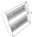
- Fig. 1 is an embodiment of a lamp according to the invention outlined obliquely from below.
- the luminaire shown is a so-called “high bay luminaire", that is to say an interior luminaire which is intended for illuminating large rooms or halls and is accordingly powerful.
- the lamp is a pendant lamp that is intended to be operated suspended from a ceiling on a pendulum or a similar suspension element. Accordingly, the luminaire is designed to be arranged in a room for operation in such a way that it is surrounded on all sides by room air.
- the lamp has a light source 2 with a plurality of light-emitting elements 3 in the form of LEDs.
- the LEDs are preferably arranged on an LED board 25.
- Fig. 3 is a view of the lamp outlined from below.
- the light source 2 is elongated in the example shown, so that it extends along a longitudinal axis L.
- the LEDs of the light source 2 are arranged like a field or matrix.
- the light source 2 can comprise a plurality of LEDs, preferably more than 30 LEDs, particularly preferably more than 50 LEDs. This allows the lamp to generate a correspondingly large luminous flux.
- the LEDs extend over a horizontal LED area which has a length l in the direction of the longitudinal axis L and a width b transversely thereto .
- the ratio of 1 : b can be, for example, between 4 : 1 and 20 : 1 , particularly preferably between 5: 1 and 15 : 1.
- the lamp With respect to the light source 2 or the longitudinal axis L horizontally on a first side re, here on the right next to the light source 2, the lamp has first through openings 5 and on a second side li, here on the left next to the Light source 2 second through openings 7.
- the second side li of the first side re is directed exactly opposite.
- the first and the second through openings 5, 7 are designed for an air flow for cooling the light source 2.
- the first and the second through openings 5, 7 can be formed by slots.
- the first and the second through openings 5, 7 are preferably designed as nozzles, which increase the speed of air flowing through. This can increase the cooling effect.
- the configuration is preferably such that the first through openings 5 extend parallel to the longitudinal axis L and preferably extend over the entire length l of the LED area.
- the first through openings 5 are formed in a row, that is to say in a single row.
- the first through openings 5 are preferably formed almost immediately next to the light source 2; For example, it can be provided that a distance d transverse to the longitudinal axis L between the LEDs and the first through openings 5 is smaller than the width b of the LED area.
- the first through openings 5 are in particular designed in such a way that air can flow through them from bottom to top.
- the first through openings 5 are preferably designed such that they are closed on all sides when viewed in a horizontal cross section.
- the design is further preferably such that - viewed in the horizontal cross section - for each of the first through openings 5, an inner diameter e transverse to the longitudinal axis L is smaller than the width b of the LED area.
- the cross-sectional shape of the first through openings 5 can be circular or rectangular to a first approximation, in particular the ratio of an inner diameter f in the direction of the longitudinal axis L to the inner diameter e, that is to say transversely thereto, being between 0.3 and 3, particularly preferably between 0, 5 and 2.
- the second through openings 7 also preferably extend parallel to the longitudinal axis L and almost directly next to the light source 2; for example can be provided - analogously to the above - that a further distance d 'transverse to the longitudinal axis L between the LEDs and the second through openings 7 is smaller than the width b of the LED area.
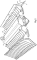
- Fig. 2 is a perspective view of the lamp from obliquely sketched, in Fig. 4 a cross section normal to the longitudinal axis L.
- the LEDs or the LED area are preferably arranged in a horizontal plane E.
- the lamp further also has the first side RE or to the right of the first passage openings 5 and thereby below the light source 2 and the plane E, a first air guide surface 6, and on the second side li or left of the second through holes 7 and thereby Below the light source 2 or the plane E, a second air guide surface 8.
- the two air guide surfaces 6, 8 are designed such that an air inflow region A is formed by them, which widens away from the light source 2.
- the two air guiding surfaces 6, 8 can be designed such that they diverge in one direction away from the light source 2, in particular toward the bottom.
- the air inflow region A which is formed by the two air guiding surfaces 6, 8, is funnel-shaped, in particular when viewed in a cross section normal to the longitudinal axis L , narrowing upward toward the light source 2.
- the two air guiding surfaces 6, 8 make it possible for air that enters the air inflow region A from below to be directed in a targeted manner to the first and second through openings 5, 7. A heat emission from the inner walls of the through openings 5, 7 to the environment is thereby significantly increased.
- the two air guiding surfaces 6, 8 are designed in profile form, each extending parallel to the longitudinal axis L.
- the first air guide surface 8 preferably has a longitudinal extension ⁇ in the direction of the longitudinal axis L which is at least half as long as the length l of the LED area; the longitudinal extent ⁇ is preferably at least three-fourths the length l . How out Fig. 3 emerges, applies in the example shown ⁇ > l . The same applies to the corresponding longitudinal extent of the second air guide surface 8.
- the first air guide surface 6 preferably has an area size that is at least as large as half the area size of the LED area, particularly preferably at least as large as the area size of the LED area. The same applies to the area size of the second air guide surface 8.
- the first air guide surface 6 extends downward to a level which lies below the plane E by a height difference ⁇ h , it preferably being the case that this height difference ⁇ h is at least half as large as the width b of the LED areas, i.e. ⁇ h> 0.5 b. ⁇ h> 0.9 b preferably applies .
- ⁇ h is at least half as large as the width b of the LED areas
- the design is such that the first air guide surface 6 directly adjoins the first through openings 5. As a result, the air is conducted directly to the first through openings 5. The same applies to the second air guide surface 8 and the second through openings 7.
- the first air-guiding surface 6 is preferably at least in a first approximation flat or curved, in particular concavely curved, wherein it has a first surface normal N1 , which includes a first angle ⁇ with a vertical V , which is between 20 ° and 85 °.
- the first angle ⁇ is preferably between 30 ° and 70 °, in the example shown approximately 45 °.
- the second air guide surface 8 which accordingly has a second surface normal N2, which includes a second, correspondingly large angle ⁇ with the vertical V.
- a particularly simple design can be achieved if the first through openings 5 are designed as parts of a heat sink 4, the heat sink 4 being designed in particular for cooling the light source 2.
- the heat sink 4 is - as is known per se from the prior art - connected to the light source 2 with good thermal conductivity.
- Fig. 5 is shown a sketch in the manner of an exploded view, which represents a slightly modified version.
- points the heat sink 4 preferably has a horizontal, flat, downward-facing surface 49 on which the light source 2 or the LED circuit board 25 is arranged.
- an optical element 27 can be provided for influencing a light emitted by the LEDs and / or a translucent cover element for protecting the LEDs.
- the optical element 27 or the cover element are preferably designed such that they extend to the first side re up to the first through openings 5 and to the second side li up to the second through openings 7.
- a holding element 29 is preferably provided which holds the above-mentioned components from below.
- the holding element 29 preferably has latching elements 28 which are designed for mechanical connection to the heat sink 4.
- the first air guide surface 6 is also advantageously formed by the heat sink 4.
- the heat sink 4 preferably consists of one piece, so it is preferably in one piece.
- it is made of aluminum.
- the heat sink 4 advantageously has - in Fig. 4 exemplified designated - fins 41 on opposite particular one of the first air guide surface 6 side, that re on the first side can or right of the first air guide 6.
- only connecting portions are formed with surfaces 42 which are inclined with respect to the horizontal, preferably inclined at least 30 °, particularly preferably at least 40 °.
- the surfaces 42 to the right of the first air guide surface 6 are inclined approximately as much as the first air guide surface 6, that is to say approximately 45 °, in a particularly material-saving manner.
- the cooling fins 41 are formed parallel to one another, in particular in planes that are oriented normal to the direction of the longitudinal axis L.
- the heat sink 4 also further, in particular vertical cooling fins 43, which are designed such that they re on the first side and are formed above the right and on the second side li or left over the light source 2 addition.
- a region 44 of the further cooling fins 43 protruding on the second side li can be designed to form the second through openings 7, and a region protruding on the first side re to form the first through openings 5.
- the further cooling fins are also 41 in the example shown are formed parallel to one another, in particular in planes which are oriented normal to the direction of the longitudinal axis L.
- the first air guide surface 6 is preferably designed to be reflective, for example painted white, in particular painted white. In this way, the light output of the lamp can be influenced advantageously.
- the inclination of the first air guide 6 in dependence - - in particular can be a lateral boundary of the light output to the first page re cause out.
- a correspondingly white design of the two air guiding surfaces 6, 8 also ensures that the luminaire, when viewed from below, shows a relatively large, brightly luminous surface via which light is emitted.
- the second air guide surface 8 is preferably formed by an outer surface of a housing 9.
- the housing 9 can be designed in particular for mounting an operating device 10, for example in the form of a converter of the lamp.
- the operating device 10 is arranged laterally next to the light source 2, here on the second side li next to the light source 2. This is advantageous because the operating device 10 is thereby arranged virtually thermally separated from the light source 2 leaves.
- the design can be such that the operating device 10 is arranged outside the vertical projection of the light source 2, particularly preferably outside the vertical projection of the heat sink 4.
- the housing 9 can have an interior 19, the vertical projection of which runs outside the projection of the light source 2.
- a good thermal separation between the operating device 10 and the light source 2 is important because an operating device is generally relatively sensitive to high temperatures.
- the thermal separation between the light source 2 and the operating device 10 is further promoted in the example shown in that the heat sink 4 is mechanically supported with the housing 9 only by a quasi-selective connection 11, for example a screw connection.
- a quasi-selective connection 11 for example a screw connection.
- the housing 10 has for this purpose preferably one, to the first page re projecting towards the flange 14, at which the connection 11 is formed, whereby the flange portion 14 outside the vertical projection of the operating device 10 and the inner space 19 is located.
- the area 44 of the further cooling fins 43 of the heat sink 4 protruding on the second side L 1 is preferably designed in such a way that it does not extend completely to the housing 10 at the level of the light source 2, but is at a distance h from the latter which is preferably between 1 mm and 10 mm.
- the second through openings 7 can therefore be designed on the one hand by the heat sink 4, more precisely by the further cooling fins 43 on the one hand and the housing 9 on the other hand.
- the flange region 14 or the connection 11 is preferably formed at a level above the plane E, in particular above the light source 2.
- the heat sink 4 is advantageously shaped such that it has an upwardly projecting region 45 on the second side li , at the upper end of which the connection 11 is formed.
- the heat sink 4 also has, on the first side re, a further region 46 projecting upwards, through which, in particular an upper end region of the first through openings 5 can be formed.
- An upper end region of the cooling fins 41 mentioned first can also be formed by the further region 46 which projects upwards.
- the heat sink 4 has a profile-shaped portion 48 which extends along the longitudinal axis L and which - viewed in cross section normal to the longitudinal axis L - has two legs, namely a lower leg 48 'and an upper leg 48 ";
- the first air guide surface 6 is formed by the lower leg 48 '.
- the upper leg 48 "extends - in particular vertically - upwards and forms the highest point of the further upwardly projecting area 46 of the heat sink 4. This is particularly a fluidic advantageous embodiment of the first through openings 5 achieved.
- the housing 9 is advantageously designed as a profile part which extends parallel to the longitudinal axis L. This enables a particularly simple manufacture of the housing 9. In addition, with this design it can be achieved that the operating device 10 can simply be pushed into the housing 9 in the direction of the longitudinal axis L in order to install the operating device 10 in the housing 9.
- a particularly powerful light can be achieved if a further light source 2 'is provided on the second side left or left of the housing 9, preferably at the same level as the light source 2 mentioned first.
- the further light source 2' can be analog or be constructed identically to the first-mentioned light source 2.
- the luminaire for cooling the further light source 2 ′ has a further heat sink 4 ′, which is preferably designed analogously or structurally identical to the heat sink 4 mentioned first.
- the luminaire is particularly preferably designed symmetrically to a vertical plane of symmetry S, which runs in particular parallel to the longitudinal axis L and thereby through the housing 9.
- the luminaire can thus be constructed in a modular manner, so to speak, with a central module comprising the housing 9 with the operating device 10 and on both sides right , left next to the central module each an LED module with associated heat sink 4, 4 'is arranged.
- the modules mentioned are preferably connected to one another for mechanical mounting only via the screw connections mentioned above.
- Luminous fluxes of more than 10,000 Im can be generated with the luminaire according to the invention.
- the lamp is also suitable, for example, for being connected to a further, structurally identical lamp, so that the two lamps are arranged one behind the other in the direction of the longitudinal axis L.
- the luminous flux that is emitted by these two lamps is then twice as large as the luminous flux of one of the two lamps.
Landscapes
- Engineering & Computer Science (AREA)
- General Engineering & Computer Science (AREA)
- Arrangement Of Elements, Cooling, Sealing, Or The Like Of Lighting Devices (AREA)
Description
- Die Erfindung betrifft eine Leuchte mit einer Lichtquelle und neben der Lichtquelle ausgebildeten Durchgangsöffnungen für eine Luftströmung zur Kühlung der Lichtquelle.
- Durch Lichtabgabeelemente, wie beispielsweise Glühbirnen, Leuchtstoffröhren, LEDs (LED: Licht emittierende Diode) u. s. w. wird im Allgemeinen Wärme in Form von Verlustwärme erzeugt, wenn sie sich in einem Zustand befinden, in dem sie Licht abstrahlen. Insbesondere, wenn eine Lichtquelle einer Leuchte als Lichtabgabeelemente LEDs aufweist, muss für einen zuverlässigen Betrieb der Leuchte dafür gesorgt werden, dass diese Wärme effektiv abtransportiert wird. Andernfalls kann es beispielsweise zu einer Beschädigung der LEDs kommen und/oder zu ungewollt verändertem Abstrahlverhalten der LEDs.
- Zur entsprechenden Kühlung von LEDs werden üblicherweise Kühlkörper verwendet, die thermisch gut leitend mit den LEDs verbunden sind. Ein LED-Downlight mit einem derartigen Kühlkörper ist beispielsweise aus der Schrift
DE 10 2010 002 235 A1 bekannt. Der Kühlkörper dieses Downlights weist vertikal gestaltete Kühlrippen auf, durch die die Oberfläche des Kühlkörpers besonders groß ist und somit eine besonders gute Wärmeabgabe an die Umgebung ermöglicht ist. Die Kühlrippen erstrecken sich dabei seitlich neben den LEDs, so dass Luft neben den LEDs entlang der Kühlrippen strömen kann, wodurch die Wärmeabgabe von den Kühlrippen an die Umgebung forciert wird. - Eine sehr effektive Wärmeabfuhr ist besonders dann wichtig, wenn die Leuchte eine sehr leistungsstarke Lichtquelle aufweist. Dies ist typischerweise bei Leuchten der Fall, die zur Beleuchtung großer Räume oder Hallen vorgesehen sind, wie so genannte "Highbay-Leuchten". Letztere sind dafür vorgesehen, in großer Höhe, beispielsweise etwa 12 m über dem Boden einer Halle, aufgehängt zu werden. Es gibt entsprechende Leuchten, die eine Lichtstromabgabe von über 10 000 Im erzeugen.
- Aus der
US 2008/0285271 A1 ist eine Leuchte mit einer LED-Lichtquelle bekannt, neben der Luftkanäle zur Kühlung der Lichtquelle ausgebildet sind. Beschreiben ist eine Pendelleuchte, bei der eine zentrale Lichtquelle durch einen trichterartigen Mantel umgeben ist, der einen Kamineffekt bewirkt, um eine effiziente Wärmeableitung zu ermöglichen. - Aus der
US 2011/0018418 A1 ist ferner ein LED-Leuchtmittel bekannt, bei dem neben einer LED-Platine ein Lamellenbereich gebildet sind, durch den kühlende Luft hindurch strömen kann. - Ferner ist aus der
US 2011/0013402 A1 eine LED-Leuchte mit einem Kühlkörper bekannt, der durch Lamellen gebildete Kühlkanäle aufweist. - Schließlich zeigt die
WO 2011/157836 A1 eine LED-Leuchte, bei der neben der LED-Lichtquelle Luftkanäle ausgebildet sind. - Der Erfindung liegt die Aufgabe zugrunde, eine entsprechende verbesserte Leuchte anzugeben. Insbesondere soll sich die Leuchte materialsparend gestalten lassen und sich durch ein verbessertes thermisches Verhalten auszeichnen.
- Diese Aufgabe wird gemäß der Erfindung mit dem in dem unabhängigen Anspruch genannten Gegenstand gelöst. Besondere Ausführungsarten der Erfindung sind in den abhängigen Ansprüchen angegeben.
- Gemäß der Erfindung ist eine Leuchte vorgesehen, die eine Lichtquelle mit mehreren Lichtabgabeelementen aufweist, wobei die Leuchte auf einer ersten Seite neben der Lichtquelle erste Durchgangsöffnungen aufweist und auf einer zweiten Seite neben der Lichtquelle zweite Durchgangsöffnungen aufweist. Dabei sind die ersten und die zweiten Durchgangsöffnungen für eine Luftströmung zur Kühlung der Lichtquelle ausgestaltet. Weiterhin weist die Leuchte auf der ersten Seite neben den ersten Durchgangsöffnungen und dabei unterhalb der Lichtquelle eine erste Luftleitfläche auf und auf der zweiten Seite neben den zweiten Durchgangsöffnungen und dabei unterhalb der Lichtquelle eine zweite Luftleitfläche, wobei die beiden Luftleitflächen derart gestaltet sind, dass durch sie ein, sich von der Lichtquelle weg erweiternder Luftanströmbereich gebildet ist. Die ersten Durchgangsöffnungen und die erste Luftleitfläche sind dabei als Teile eines Kühlkörpers gestaltet, der eine plane, nach unten weisende Fläche aufweist, auf der die Lichtquelle angeordnet ist.
- Durch den von den beiden Luftleitflächen gebildeten Luftanströmbereich lässt sich bewirken, dass Luft besonders gezielt zu den Durchgangsöffnungen gelenkt wird. Auf diese Weise wird eine Durchströmung der Durchgangsöffnungen forciert und damit eine besonders intensive Wärmeabgabe von den Oberflächen der Durchgangsöffnungen an die Umgebung ermöglicht. Auf diese Weise ist eine besonders effektive Kühlung der Lichtquelle erzielt.
- Vorzugsweise ist die Leuchte derart gestaltet, dass die erste Luftleitfläche unmittelbar an die ersten Durchgangsöffnungen angrenzt und/oder die zweite Luftleitfläche unmittelbar an die zweiten Durchgangsöffnungen angrenzt. Hierdurch lässt sich erzielen, dass durch die Luftleitflächen Luft besonders gezielt zu den entsprechenden Durchgangsöffnungen geleitet wird.
- Vorzugsweise ist die erste Luftleitfläche zumindest in erster Näherung plan oder gewölbt gestaltet und weist dabei insbesondere eine erste Flächennormale auf, die mit einer Vertikalen einen ersten Winkel einschließt, der zwischen 20° und 85° beträgt, vorzugsweise zwischen 30° und 70°, besonders bevorzugt zwischen 35° und 60°. Hierdurch ist eine besonders effektive Luftleitung ermöglicht. Weiterhin vorzugsweise ist auch die zweite Luftleitfläche zumindest in erster Näherung plan oder gewölbt gestaltet und weist dabei insbesondere eine zweite Flächennormale auf, die mit der Vertikalen einen zweiten Winkel einschließt, der zwischen 20° und 85° beträgt, vorzugsweise zwischen 30° und 70°, besonders bevorzugt zwischen 35° und 60°. Auch hierdurch ist eine besonders effektive Luftleitung ermöglicht.
- Vorzugsweise weist dabei der Kühlkörper vertikal verlaufende Kühlrippen auf, insbesondere auf einer, der ersten Luftleitfläche gegenüberliegenden Seite. Wenn dabei der Kühlkörper derart gestaltet ist, dass zwischen den Kühlrippen lediglich Verbindungsbereiche gebildet sind, deren Oberflächen mindestens 30°, vorzugsweise mindestens 40° gegenüber der Horizontalen geneigt sind, lässt sich eine mögliche Ablagerung von Staub oder dergleichen bei Betrieb der Leuchte effektiv vermindern.
- Die erste Luftleitfläche und/oder die zweite Luftleitfläche sind vorteilhaft reflektierend gestaltet, vorzugsweise dabei weiß, insbesondere weiß lackiert. Hierdurch können sie für ein von der Lichtquelle abgestrahltes Licht als Reflektor wirken. Insbesondere lässt sich hierdurch ein Abstrahlbereich der Leuchte beeinflussen bzw. begrenzen.
- Vorzugsweise ist die zweite Luftleitfläche durch eine Außenfläche eines Gehäuses gebildet, wobei vorzugsweise das Gehäuse zur Lagerung eines Betriebsgeräts der Leuchte ausgestaltet ist. Hierdurch lässt sich die Leuchte besonders materialsparend und dabei thermisch vorteilhaft gestalten. Thermisch vorteilhaft ist die Leuchte dabei weiterhin vorzugsweise derart gestaltet, dass das Gehäuse einen Innenraum aufweist, dessen vertikale Projektion außerhalb der vertikalen Projektion der Lichtquelle verläuft.
- Thermisch und herstellungstechnisch vorteilhaft ist das Gehäuse profilförmig gestaltet.
- Eine besonders geeignete thermische Trennung zwischen dem Gehäuse bzw. dem darin befindlichen Betriebsgerät einerseits und der Lichtquelle andererseits lässt sich erzielen, wenn das Gehäuse mit dem Kühlkörper lediglich über eine Schraubverbindung mechanisch gehaltert verbunden ist.
- Vorzugsweise weist die Leuchte außerdem eine weitere Lichtquelle auf, die auf der zweiten Seite neben dem Gehäuse angeordnet ist, wobei die weitere Lichtquelle vorzugsweise analog oder baugleich zu der zuerst genannten Lichtquelle gestaltet ist. Dabei weist die Leuchte weiterhin vorzugsweise einen weiteren Kühlkörper zur Kühlung der weiteren Lichtquelle auf, der auf der zweiten Seite neben dem Gehäuse angeordnet ist, wobei der weitere Kühlkörper vorzugsweise analog oder baugleich zu dem zuerst genannten Kühlkörper gestaltet ist.
- Eine besonders leistungsstarke und herstellungstechnisch vorteilhafte Leuchte lässt sich erzielen, wenn die Leuchte mit Bezug auf eine vertikale Symmetrieebene symmetrisch gestaltet ist. Die Symmetrieebene verläuft dabei vorzugsweise durch das Gehäuse.
- Die Erfindung wird im Folgenden anhand eines Ausführungsbeispiels und mit Bezug auf die Zeichnungen näher erläutert. Es zeigen:
- Fig. 1
- eine perspektivische Skizze einer erfindungsgemäßen Leuchte von schräg unten,
- Fig. 2
- eine entsprechende Skizze von schräg oben,
- Fig. 3
- eine Ansicht von unten,
- Fig. 4
- eine Querschnitt-Skizze und
- Fig. 5
- eine Skizze nach Art einer Explosionsdarstellung zu Aufbau und Halterung der Lichtquelle am Kühlkörper.
- In
Fig. 1 ist ein Ausführungsbeispiel einer erfindungsgemäßen Leuchte von schräg unten skizziert. Bei der gezeigten Leuchte handelt es sich um eine so genannte "Highbay-Leuchte", also eine Innenraum-Leuchte, die zur Beleuchtung großer Räume bzw. Hallen vorgesehen ist und dementsprechend leistungsstark ist. Im gezeigten Beispiel handelt es sich bei der Leuchte um eine Pendelleuchte, die dafür vorgesehen ist, an einem Pendel oder einem ähnlichem Abhänge-Element von einer Decke abgehängt betrieben zu werden. Dementsprechend ist die Leuchte dafür konzipiert, zum Betrieb derart in einem Raum angeordnet zu werden, dass sie allseitig von RaumLuft umgeben ist. - Die Leuchte weist eine Lichtquelle 2 mit mehreren Lichtabgabeelementen 3 in Form von LEDs auf. Die LEDs sind dabei vorzugsweise auf einer LED-Platine 25 angeordnet.
- In
Fig. 3 ist eine Ansicht der Leuchte von unten skizziert. Die Lichtquelle 2 ist im gezeigten Beispiel länglich gestaltet, so dass sie sich entlang einer Längsachse L erstreckt. - Die LEDs der Lichtquelle 2 sind feld- oder matrixartig angeordnet. Insbesondere kann die Lichtquelle 2 mehrere LEDs umfassen, vorzugsweise mehr als 30 LEDs, besonders bevorzugt mehr als 50 LEDs. Hierdurch lässt sich mit der Leuchte ein entsprechend großer Lichtstrom erzeugen.
- Die LEDs erstrecken sich über ein horizontales LED-Areal, das in Richtung der Längsachse L eine Länge l aufweist und quer dazu eine Breite b. Das Verhältnis von l : b kann dabei beispielsweise zwischen 4 : 1 und 20 : 1 betragen, besonders bevorzugt zwischen 5 : 1 und 15 : 1.
- Mit Bezug auf die Lichtquelle 2 bzw. die Längsachse L horizontal auf einer ersten Seite re, hier rechts neben der Lichtquelle 2 weist die Leuchte erste Durchgangsöffnungen 5 auf und auf einer zweiten Seite li, hier links neben der Lichtquelle 2 zweite Durchgangsöffnungen 7. Insbesondere ist dabei die zweite Seite li der ersten Seite re genau entgegen gerichtet.
- Die ersten und die zweiten Durchgangsöffnungen 5, 7 sind für eine Luftströmung zur Kühlung der Lichtquelle 2 ausgestaltet. Die ersten und die zweiten Durchgangsöffnungen 5, 7 können durch Schlitze gebildet sein. Die ersten und die zweiten Durchgangsöffnungen 5, 7 sind vorzugsweise als Düsen gestaltet, die eine Erhöhung der Geschwindigkeit einer durchströmenden Luft bewirken. Hierdurch lässt sich die Kühlwirkung verstärken.
- Vorzugsweise ist die Gestaltung derart, dass sich die ersten Durchgangsöffnungen 5 parallel zu der Längsachse L erstrecken und dabei vorzugsweise über die gesamte Länge l des LED-Areals erstrecken. Im gezeigten Beispiel sind die ersten Durchgangsöffnungen 5 in einer Reihe, also sozusagen einreihig gebildet.
- Weiterhin vorzugsweise sind die ersten Durchgangsöffnungen 5 quasi unmittelbar neben der Lichtquelle 2 ausgebildet; beispielsweise kann vorgesehen sein, dass ein Abstand d quer zu der Längsachse L zwischen den LEDs und den ersten Durchgangsöffnungen 5 kleiner ist als die Breite b des LED-Areals.
- Die ersten Durchgangsöffnungen 5 sind insbesondere derart gestaltet, dass eine Luft von unten nach oben durch sie hindurch strömen kann. Vorzugsweise sind die ersten Durchgangsöffnungen 5 derart gestaltet, dass sie in einem horizontalen Querschnitt betrachtet allseits geschlossen sind. Dabei ist die Gestaltung weiterhin vorzugsweise so, dass - in dem horizontalen Querschnitt betrachtet - für jede der ersten Durchgangsöffnungen 5 ein Innendurchmesser e quer zur Längsachse L kleiner ist als die Breite b des LED-Areals. Die Querschnittform der ersten Durchgangsöffnunen 5 kann dabei in erster Näherung kreisförmig oder rechteckig sein, wobei insbesondere das Verhältnis eines Innendurchmessers f in Richtung der Längsachse L zu dem Innendurchmesser e, also quer dazu, zwischen 0,3 und 3 beträgt, besonders bevorzugt zwischen 0,5 und 2 beträgt.
- Auch die zweiten Durchgangsöffnungen 7 erstrecken sich vorzugsweise parallel zu der Längsachse L und dabei quasi unmittelbar neben der Lichtquelle 2; beispielsweise kann - analog zu oben - vorgesehen sein, dass ein weiterer Abstand d' quer zu der Längsachse L zwischen den LEDs und den zweiten Durchgangsöffnungen 7 kleiner ist als die Breite b des LED-Areals.
- In
Fig. 2 ist eine perspektivische Ansicht der Leuchte von schräg oben skizziert, inFig. 4 ein Querschnitt normal zu der Längsachse L. Wie inFig. 4 angedeutet und oben bereits erwähnt, sind die LEDs bzw. ist das LED-Areal vorzugsweise in einer horizontalen Ebene E angeordnet. - Die Leuchte weist weiterhin auf der ersten Seite re bzw. rechts neben den ersten Durchgangsöffnungen 5 und dabei unterhalb der Lichtquelle 2 bzw. der Ebene E eine erste Luftleitfläche 6 auf und auf der zweiten Seite li bzw. links neben den zweiten Durchgangsöffnungen 7 und dabei ebenfalls unterhalb der Lichtquelle 2 bzw. der Ebene E eine zweite Luftleitfläche 8. Die beiden Luftleitflächen 6, 8 sind dabei derart gestaltet, dass durch sie ein Luftanströmbereich A gebildet ist, der sich von der Lichtquelle 2 weg erweitert. Insbesondere können die beiden Luftleitflächen 6, 8 derart ausgestaltet sein, dass sie in einer Richtung von der Lichtquelle 2 fort, insbesondere nach unten zu, divergieren. Der Luftanströmbereich A, der durch die beiden Luftleitflächen 6, 8 gebildet ist, ist - insbesondere in einem Querschnitt normal zu der Längsachse L betrachtet - trichterförmig, wobei er sich nach oben, zu der Lichtquelle 2 hin verengt.
- Durch die beiden Luftleitflächen 6, 8 lässt sich erzielen, dass Luft, die von unten in den Luftanströmbereich A eintritt, gezielt zu den ersten und zweiten Durchgangsöffnungen 5, 7 gelenkt wird. Eine Wärmeabgabe von den Innenwänden der Durchgangsöffnungen 5, 7 an die Umgebung wird hierdurch signifikant forciert.
- Im gezeigten Beispiel sind die beiden Luftleitflächen 6, 8 profilförmig gestaltet, wobei sie sich jeweils parallel zu der Längsachse L erstrecken. Wie in
Fig. 3 beispielhaft skizziert, weist vorzugsweise die erste Luftleitfläche 8 in Richtung der Längsachse L eine Längserstreckung λ auf, die wenigstens halb so groß ist wie die Länge l des LED-Areals; vorzugsweise beträgt die Längserstreckung λ mindestens das Dreiviertelfache der Länge l. Wie ausFig. 3 hervorgeht, gilt im gezeigten Beispiel λ > l. Für die entsprechende Längserstreckung der zweiten Luftleitfläche 8 gilt Analoges. - Die erste Luftleitfläche 6 weist vorzugsweise eine Flächengröße auf, die mindestens so groß ist wie die Hälfte der Flächengröße des LED-Areals, besonders bevorzugt mindestens so groß wie die Flächengröße des LED-Areals. Analoges gilt für die Flächengröße der zweiten Luftleitfläche 8.
- Wie in Fig. 6 gezeigt, erstreckt sich die erste Luftleitfläche 6 nach unten hin bis auf ein Niveau, das um eine Höhendifferenz Δh unterhalb der Ebene E liegt, wobei vorzugsweise gilt, dass diese Höhendifferenz Δh wenigstens halb so groß ist wie die Breite b des LED-Areals, also Δh > 0,5 b. Vorzugsweise gilt Δh > 0,9 b. Analoges gilt wiederum für die zweite Luftleitfläche 8.
- Im gezeigten Beispiel ist die Gestaltung derart, dass die erste Luftleitfläche 6 unmittelbar an die ersten Durchgangsöffnungen 5 angrenzt. Hierdurch wird die Luft unmittelbar zu den ersten Durchgangsöffnungen 5 geleitet. Analoges gilt für die zweite Luftleitfläche 8 und die zweiten Durchgangsöffnungen 7.
- Die erste Luftleitfläche 6 ist vorzugsweise zumindest in erster Näherung plan oder gewölbt, insbesondere konkav gewölbt gestaltet, wobei sie eine erste Flächennormale N1 aufweist, die mit einer Vertikalen V einen ersten Winkel α einschließt, der zwischen 20° und 85° beträgt. Vorzugsweise beträgt der erste Winkel α zwischen 30° und 70°, im gezeigten Beispiel etwa 45°. Analoges gilt wiederum mit Bezug auf die zweite Luftleitfläche 8, die dementsprechend eine zweite Flächennormale N2 aufweist, die mit der Vertikalen V einen zweiten, entsprechend großen Winkel β einschließt.
- Eine besonders einfache Gestaltung lässt sich erzielen, wenn die ersten Durchgangsöffnungen 5 als Teile eines Kühlkörpers 4 gestaltet sind, wobei der Kühlkörper 4 insbesondere zur Kühlung der Lichtquelle 2 gestaltet ist. Der Kühlkörper 4 ist dabei - wie an sich aus dem Stand der Technik bekannt - gut wärmeleitend mit der Lichtquelle 2 verbunden.
- In
Fig. 5 ist eine Skizze nach Art einer Explosionsdarstellung gezeigt, die eine leicht modifizierte Ausführung darstellt. Wie aus dieser Figur beispielhaft hervorgeht, weist der Kühlkörper 4 vorzugsweise eine horizontale, plane, nach unten weisende Fläche 49 auf, auf der die Lichtquelle 2 bzw. die LED-Platine 25 angeordnet ist. - Den LEDs optisch nachfolgend kann ein optisches Element 27 zur Beeinflussung eines von den LEDs abgestrahlten Lichts vorgesehen sein und/oder ein lichtdurchlässiges Abdeckelement zum Schutz der LEDs. Das optische Element 27 bzw. das Abdeckelement sind dabei vorzugsweise derart gestaltet, dass sie sich zur ersten Seite re hin maximal bis zu den ersten Durchgangsöffnungen 5 hin erstrecken und zur zweiten Seite li hin maximal bis zu den zweiten Durchgangsöffnungen 7.
- Zur mechanischen Halterung der LED-Platine 25 und gegebenenfalls des optischen Elements 27 bzw. des Abdeckelements ist vorzugsweise ein Halteelement 29 vorgesehen, das die genannten Komponenten von unten umgreifend hält. Vorzugsweise weist das Halteelement 29 dabei Rastelemente 28 auf, die zur mechanischen Verbindung mit dem Kühlkörper 4 ausgebildet sind.
- Im gezeigten Beispiel ist vorteilhaft auch die erste Luftleitfläche 6 durch den Kühlkörper 4 gebildet. Der Kühlkörper 4 besteht dabei vorzugsweise aus einem Stück, ist also vorzugsweise einstückig. Beispielsweise besteht er aus Aluminium.
- Weiterhin weist der Kühlkörper 4 vorteilhaft - in
Fig. 4 beispielhaft bezeichnete - Kühlrippen 41 auf, insbesondere auf einer, der ersten Luftleitfläche 6 gegenüberliegenden Seite, also auf der ersten Seite re bzw. rechts von der ersten Luftleitfläche 6. Hierdurch lässt sich materialsparend erzielen, dass zwischen den Kühlrippen 41 durch den Kühlkörper 4 lediglich Verbindungsbereiche mit Oberflächen 42 gebildet sind, die gegenüber der Horizontalen geneigt sind, vorzugsweise mindestens 30°, besonders bevorzugt mindestens 40° geneigt sind. Im gezeigten Beispiel sind - besonders materialsparend - die Oberflächen 42 rechts von der ersten Luftleitfläche 6 etwa ebenso stark geneigt wie die erste Luftleitfläche 6, also etwa 45°. Durch entsprechend geneigte Oberflächen 42 lässt sich bei Betrieb der Leuchte - im Vergleich zu einer entsprechenden horizontalen Oberflächengestaltung - eine Ablagerung von Staub, Schmutz etc. besonders effektiv vermindern. - Die Kühlrippen 41 sind im gezeigten Beispiel parallel zueinander ausgebildet, insbesondere in Ebenen, die normal zu der Richtung der Längsachse L orientiert sind.
- Vorteilhaft weist der Kühlkörper 4 außerdem weitere, insbesondere vertikale Kühlrippen 43 auf, die derart gestaltet sind, dass sie auf der ersten Seite re bzw. rechts und auf der zweiten Seite li bzw. links über die Lichtquelle 2 hinaus vorstehend ausgebildet sind. Ein auf der zweiten Seite li vorstehender Bereich 44 der weiteren Kühlrippen 43 kann zur Bildung der zweiten Durchgangsöffnungen 7 gestaltet sein, ein auf der ersten Seite re vorstehende Bereich zur Bildung der ersten Durchgangsöffnungen 5. Wie die zuerst genannten Kühlrippen 41, sind auch die weiteren Kühlrippen 41 im gezeigten Beispiel parallel zueinander ausgebildet, insbesondere in Ebenen, die normal zu der Richtung der Längsachse L orientiert sind.
- Vorzugsweise ist die erste Luftleitfläche 6 reflektierend gestaltet, beispielsweise weiß, insbesondere weiß lackiert. Auf diese Weise lässt sich die Lichtabgabe der Leuchte vorteilhaft beeinflussen. Insbesondere lässt sich - in Abhängigkeit der Neigung der ersten Luftleitfläche 6 - eine seitliche Begrenzung der Lichtabgabe zur ersten Seite re hin bewirken. Analoges gilt mit Bezug auf die zweite Luftleitfläche 8 auf der zweiten Seite li. Mit anderen Worten lässt sich hierdurch ein Winkelbereich festlegen, in dem eine Lichtabgabe der Leuchte erfolgt.
- Durch eine entsprechend weiße Gestaltung der beiden Luftleitflächen 6, 8 wird außerdem erzielt, dass die Leuchte bei Betrachtung von unten eine relativ große, hellleuchtende Fläche zeigt, über die Licht abgegeben wird.
- Vorzugsweise ist die zweite Luftleitfläche 8 durch eine Außenfläche eines Gehäuses 9 gebildet. Das Gehäuse 9 kann insbesondere zur Lagerung eines Betriebsgeräts 10, beispielsweise in Form eines Konverters der Leuchte ausgestaltet sein. Auf diese Weise lässt sich vorteilhaft erzielen, dass das Betriebsgerät 10 seitlich neben der Lichtquelle 2 angeordnet ist, hier auf der zweiten Seite li neben der Lichtquelle 2. Dies ist von Vorteil, weil sich das Betriebsgerät 10 dadurch quasi thermisch getrennt von der Lichtquelle 2 anordnen lässt. Insbesondere kann die Gestaltung derart sein, dass das Betriebsgerät 10 außerhalb der vertikalen Projektion der Lichtquelle 2 angeordnet ist, besonders bevorzugt außerhalb der vertikalen Projektion des Kühlkörpers 4.
- Das Gehäuse 9 kann hierzu einen Innenraum 19 aufweisen, dessen vertikale Projektion außerhalb der Projektion der Lichtquelle 2 verläuft.
- Eine gute thermische Trennung zwischen dem Betriebsgerät 10 und der Lichtquelle 2 ist von Bedeutung, weil ein Betriebsgerät im Allgemeinen relativ sensibel auf hohe Temperaturen reagiert.
- Die thermische Trennung zwischen der Lichtquelle 2 und dem Betriebsgerät 10 ist im gezeigten Beispiel weiterhin dadurch gefördert, dass der Kühlkörper 4 mit dem Gehäuse 9 mechanisch gehaltert lediglich über eine quasi punktuell wirkende Verbindung 11, beispielsweise eine Schraubverbindung verbunden ist. Beispielsweise können hierzu lediglich zwei - beispielhaft in
Fig. 2 gezeigte - Schrauben 12 vorgesehen sein. Das Gehäuse 10 weist hierzu vorzugsweise einen, zur ersten Seite re hin vorstehenden Flanschbereich 14 auf, an dem die Verbindung 11 ausgebildet ist, wobei sich der Flanschbereich 14 außerhalb der vertikalen Projektion des Betriebsgeräts 10 bzw. des Innenraums 19 befindet. - Der auf der zweiten Seite li vorstehende Bereich 44 der weiteren Kühlrippen 43 des Kühlkörpers 4 ist hierzu vorzugsweise derart gestaltet, dass er sich - auf Höhe der Lichtquelle 2 - nicht ganz bis zu dem Gehäuse 10 hin erstreckt, sondern zu Letzterem einen Abstand h aufweist, der vorzugsweise zwischen 1 mm und 10 mm beträgt. Die zweiten Durchgangsöffnungen 7 können also einerseits durch den Kühlkörper 4, genauer durch die weiteren Kühlrippen 43 einerseits und das Gehäuse 9 andererseits gestaltet sein.
- Der Flanschbereich 14 bzw. die Verbindung 11 ist vorzugsweise auf einem Niveau oberhalb der Ebene E, insbesondere oberhalb der Lichtquelle 2 gebildet. Dabei ist der Kühlkörper 4 vorteilhaft derart geformt, dass er auf der zweiten Seite li einen nach oben hin vorragenden Bereich 45 aufweist, an dessen oberem Ende die Verbindung 11 ausgebildet ist.
- Strömungstechnisch vorteilhaft weist der Kühlkörper 4 außerdem auf der ersten Seite re einen weiteren, nach oben hin vorragenden Bereich 46 auf, durch den insbesondere ein oberer Endbereich der ersten Durchgangsöffnungen 5 gebildet sein kann. Auch ein oberer Endbereich der zuerst genannten Kühlrippen 41 kann durch den weiteren, nach oben hin vorragenden Bereich 46 gebildet sein.
- Im gezeigten Beispiel weist der Kühlkörper 4 einen profilförmigen Anteil 48 auf, der sich entlang der Längsachse L erstreckt und der - in einem Querschnitt normal zu der Längsachse L betrachtet - zwei Schenkel aufweist, nämlich einen unteren Schenkel 48' und einen oberen Schenkel 48"; durch den unteren Schenkel 48' ist dabei die erste Luftleitfläche 6 gebildet. Der obere Schenkel 48" erstreckt sich - insbesondere vertikal ausgebildet - nach oben und bildet den höchsten Punkt des weiteren nach oben hin vorragenden Bereichs 46 des Kühlkörpers 4. Hierdurch ist insbesondere eine strömungstechnisch vorteilhafte Ausführung der ersten Durchgangsöffnungen 5 erzielt.
- Das Gehäuse 9 ist vorteilhaft als Profilteil gestaltet, das sich parallel zu der Längsachse L erstreckt. Hierdurch ist eine besonders einfache Herstellung des Gehäuses 9 ermöglicht. Außerdem lässt sich bei dieser Gestaltung erzielen, dass sich zum Einbau des Betriebsgeräts 10 in das Gehäuse 9 das Betriebsgerät 10 einfach in Richtung der Längsachse L in das Gehäuse 9 einschieben lässt.
- Eine besonders leistungsstarke Leuchte lässt sich erzielen, wenn auf der zweiten Seite li bzw. links neben dem Gehäuse 9 eine weitere Lichtquelle 2' vorgesehen ist, vorzugsweise auf demselben Niveau wie die zuerst genannte Lichtquelle 2. Insbesondere kann die weitere Lichtquelle 2' analog bzw. baugleich zu der zuerst genannten Lichtquelle 2 gestaltet sein. Dementsprechend weiterhin vorteilhaft weist die Leuchte zur Kühlung der weiteren Lichtquelle 2' einen weiteren Kühlkörper 4' auf, der vorzugswiese analog bzw. baugleich zu dem, zuerst genannten Kühlkörper 4 gestaltet ist.
- Besonders bevorzugt ist die Leuchte symmetrisch zu einer vertikalen Symmetrieebene S gestaltet, die insbesondere parallel zu der Längsachse L und dabei durch das Gehäuse 9 verläuft.
- Die Leuchte lässt sich also sozusagen modular aufbauen, wobei ein zentrales Modul das Gehäuse 9 mit dem Betriebsgerät 10 umfasst und zu beiden Seiten re, li neben dem zentralen Modul jeweils ein LED-Modul mit dazugehörigem Kühlkörper 4, 4' angeordnet ist. Die genannten Module sind dabei zur mechanischen Halterung vorzugsweise lediglich über die oben genannten Schraubverbindungen miteinander verbunden.
- Mit der erfindungsgemäßen Leuchte lassen sich Lichtströme von mehr als 10 000 Im erzeugen. Dabei eignet sich die Leuchte auch beispielsweise dazu, mit einer weiteren, baugleichen Leuchte verbunden zu werden, so dass die beiden Leuchten in Richtung der Längsachse L hintereinander fluchtend angeordnet sind. Der Lichtstrom, der von diesen beiden Leuchten zusammen abgegeben wird, ist dann dementsprechend doppelt so groß wie der Lichtstrom einer der beiden Leuchten.
Claims (14)
- Pendelleuchte, aufweisend
eine Lichtquelle (2) mit mehreren Lichtabgabeelementen (3),
wobei die Leuchte auf einer ersten Seite (re) neben der Lichtquelle (2) erste Durchgangsöffnungen (5) aufweist und auf einer zweiten Seite (li) neben der Lichtquelle (2) zweite Durchgangsöffnungen (7) aufweist,
wobei die ersten und die zweiten Durchgangsöffnungen (5, 7) für eine Luftströmung zur Kühlung der Lichtquelle (2) ausgestaltet sind,
wobei die Leuchte weiterhin auf der ersten Seite (re) neben den ersten Durchgangsöffnungen (5) und dabei unterhalb der Lichtquelle (2) eine erste Luftleitfläche (6) aufweist und auf der zweiten Seite (li) neben den zweiten Durchgangsöffnungen (7) und dabei unterhalb der Lichtquelle (2) eine zweite Luftleitfläche (8) aufweist,
wobei die beiden Luftleitflächen (6, 8) derart gestaltet sind, dass durch sie ein, sich von der Lichtquelle (2) weg erweiternder Luftanströmbereich (A) gebildet ist, und
wobei die ersten Durchgangsöffnungen (5) und die erste Luftleitfläche (6) als Teile eines Kühlkörpers (4) gestaltet sind, der eine plane, nach unten weisende Fläche (49) aufweist, auf der die Lichtquelle (2) angeordnet ist. - Pendelleuchte nach Anspruch 1,
die derart gestaltet ist, dass die erste Luftleitfläche (6) unmittelbar an die ersten Durchgangsöffnungen 5 angrenzt und/oder die zweite Luftleitfläche (8) unmittelbar an die zweiten Durchgangsöffnungen (7) angrenzt. - Pendelleuchte nach Anspruch 1 oder 2,
bei der die erste Luftleitfläche (6) zumindest in erster Näherung plan oder gewölbt gestaltet ist und dabei vorzugsweise eine erste Flächennormale (N1) aufweist, die mit einer Vertikalen (V) einen ersten Winkel (α) einschließt, der zwischen 20° und 85° beträgt, vorzugsweise zwischen 30° und 70°, besonders bevorzugt zwischen 35° und 60°. - Leuchte nach Anspruch 3,
bei der die zweite Luftleitfläche (8) zumindest in erster Näherung plan oder gewölbt gestaltet ist und dabei vorzugsweise eine zweite Flächennormale (N2) aufweist, die mit der Vertikalen (V) einen zweiten Winkel (β) einschließt, der zwischen 20° und 85° beträgt, vorzugsweise zwischen 30° und 70°, besonders bevorzugt zwischen 35° und 60°. - Pendelleuchte nach einem der vorhergehenden Ansprüche,
bei der der Kühlkörper (4) vertikal verlaufende Kühlrippen (41) aufweist, insbesondere auf einer, der ersten Luftleitfläche (6) gegenüberliegenden Seite. - Pendelleuchte nach Anspruch 5,
bei der der Kühlkörper (4) derart gestaltet ist, dass zwischen den Kühlrippen (41) lediglich Verbindungsbereiche gebildet sind, deren Oberflächen (42) mindestens 30°, vorzugsweise mindestens 40° gegenüber der Horizontalen geneigt sind. - Pendelleuchte nach einem der vorhergehenden Ansprüche,
bei der die erste Luftleitfläche (7) und/oder die zweite Luftleitfläche (8) reflektierend gestaltet sind, vorzugsweise dabei weiß, insbesondere weiß lackiert sind. - Pendelleuchte nach einem der vorhergehenden Ansprüche,
bei der die zweite Luftleitfläche (8) durch eine Außenfläche eines Gehäuses (9) gebildet ist, wobei vorzugsweise das Gehäuse (9) zur Lagerung eines Betriebsgeräts (10) der Leuchte ausgestaltet ist. - Pendelleuchte nach Anspruch 8,
die derart gestaltet ist, dass das Gehäuse (9) einen Innenraum (19) aufweist, dessen vertikale Projektion außerhalb der vertikalen Projektion der Lichtquelle (2) verläuft. - Pendelleuchte nach Anspruch 8 oder 9,
bei dem das Gehäuse (9) profilförmig gestaltet ist. - Pendelleuchte nach einem der Ansprüche 8 bis 10,
bei der das Gehäuse (9) mit dem Kühlkörper (4) lediglich über eine Schraubverbindung mechanisch gehaltert verbunden ist. - Pendelleuchte nach einem der Ansprüche 8 bis 11,
weiterhin aufweisend
eine weitere Lichtquelle (2'), die auf der zweiten Seite (li) neben dem Gehäuse (9) angeordnet ist, wobei die weitere Lichtquelle (2') vorzugsweise analog oder baugleich zu der zuerst genannten Lichtquelle (2) gestaltet ist. - Pendelleuchte nach Anspruch 12,
weiterhin aufweisend
einen weiteren Kühlkörper (4') zur Kühlung der weiteren Lichtquelle (2'), der auf der zweiten Seite (li) neben dem Gehäuse (9) angeordnet ist, wobei der weitere Kühlkörper (4') vorzugsweise analog oder baugleich zu dem zuerst genannten Kühlkörper (4) gestaltet ist. - Pendelleuchte nach Anspruch 12 oder 13,
die mit Bezug auf eine vertikale Symmetrieebene (S) symmetrisch gestaltet ist, wobei die Symmetrieebene (S) vorzugsweise durch das Gehäuse (9) verläuft.
Applications Claiming Priority (3)
| Application Number | Priority Date | Filing Date | Title |
|---|---|---|---|
| DE102012222184.0A DE102012222184A1 (de) | 2012-12-04 | 2012-12-04 | Leuchte mit Luftleitflächen |
| PCT/EP2013/075367 WO2014086770A1 (de) | 2012-12-04 | 2013-12-03 | Leuchte mit luftleitflächen |
| EP13799063.6A EP2929237B1 (de) | 2012-12-04 | 2013-12-03 | Leuchte mit luftleitflächen |
Related Parent Applications (2)
| Application Number | Title | Priority Date | Filing Date |
|---|---|---|---|
| EP13799063.6A Division-Into EP2929237B1 (de) | 2012-12-04 | 2013-12-03 | Leuchte mit luftleitflächen |
| EP13799063.6A Division EP2929237B1 (de) | 2012-12-04 | 2013-12-03 | Leuchte mit luftleitflächen |
Publications (2)
| Publication Number | Publication Date |
|---|---|
| EP3249292A1 EP3249292A1 (de) | 2017-11-29 |
| EP3249292B1 true EP3249292B1 (de) | 2020-06-24 |
Family
ID=49683748
Family Applications (2)
| Application Number | Title | Priority Date | Filing Date |
|---|---|---|---|
| EP17174955.9A Active EP3249292B1 (de) | 2012-12-04 | 2013-12-03 | Leuchte mit luftleitflächen |
| EP13799063.6A Active EP2929237B1 (de) | 2012-12-04 | 2013-12-03 | Leuchte mit luftleitflächen |
Family Applications After (1)
| Application Number | Title | Priority Date | Filing Date |
|---|---|---|---|
| EP13799063.6A Active EP2929237B1 (de) | 2012-12-04 | 2013-12-03 | Leuchte mit luftleitflächen |
Country Status (6)
| Country | Link |
|---|---|
| US (1) | US9791142B2 (de) |
| EP (2) | EP3249292B1 (de) |
| CN (1) | CN104870891B (de) |
| DE (2) | DE102012222184A1 (de) |
| PL (1) | PL2929237T3 (de) |
| WO (1) | WO2014086770A1 (de) |
Families Citing this family (20)
| Publication number | Priority date | Publication date | Assignee | Title |
|---|---|---|---|---|
| US10234127B2 (en) | 2016-02-08 | 2019-03-19 | Cree, Inc. | LED luminaire having enhanced thermal management |
| US10203103B2 (en) | 2016-02-08 | 2019-02-12 | Cree, Inc. | LED luminaire having enhanced thermal management |
| WO2017184919A1 (en) * | 2016-04-22 | 2017-10-26 | Hubbell Incorporated | Lighting fixture |
| EP3473554B1 (de) * | 2017-10-23 | 2021-12-01 | Goodrich Lighting Systems GmbH | Flugzeugaussenlichteinheit |
| DE202019100381U1 (de) | 2019-01-24 | 2020-04-27 | Zumtobel Lighting Gmbh | Kühlkörper für eine LED-Platine |
| DE202019100380U1 (de) * | 2019-01-24 | 2020-04-27 | Zumtobel Lighting Gmbh | Anordnung zur Lichtabgabe mit veränderbarer Lichtabstrahlcharakteristik |
| CN114270092A (zh) | 2019-05-10 | 2022-04-01 | 合保照明公司 | 用于led照明器具的透镜组件 |
| DE102019112685A1 (de) * | 2019-05-15 | 2020-11-19 | Zumtobel Lighting Gmbh | Leuchte mit geschützt gelagerten Leuchtmitteln |
| DE102019112687A1 (de) | 2019-05-15 | 2020-11-19 | Zumtobel Lighting Gmbh | Wannenförmiges Leuchtengehäuse |
| DE102019112691A1 (de) * | 2019-05-15 | 2020-11-19 | Zumtobel Lighting Gmbh | Leuchte mit Kühlluftkanälen |
| DE102019112694A1 (de) | 2019-05-15 | 2020-11-19 | Zumtobel Lighting Gmbh | Leuchte mit geschützt aufgenommener Leuchtenkomponente |
| US20220311919A1 (en) * | 2019-07-30 | 2022-09-29 | Ovad Custom Stages, Llc | Light emitting diode fixtures for vehicle photographic systems |
| US11473768B2 (en) * | 2020-01-10 | 2022-10-18 | Eaton Intelligent Power Limited | Thermally conductive polymer luminaire |
| DE102020101162A1 (de) | 2020-01-20 | 2021-07-22 | Zumtobel Lighting Gmbh | Wannenförmiges Leuchtengehäuse |
| DE102020101152B4 (de) | 2020-01-20 | 2023-09-21 | Zumtobel Lighting Gmbh | Verfahren und Bausatz zum Bilden einer Leuchte |
| DE102020101166A1 (de) | 2020-01-20 | 2021-07-22 | Zumtobel Lighting Gmbh | Wannenförmiges Leuchtengehäuse |
| EP4001739B1 (de) | 2020-11-19 | 2024-01-03 | Zumtobel Lighting GmbH | Leuchte mit darin aufgenommenen leuchtenkomponenten |
| AT17531U1 (de) | 2020-11-19 | 2022-06-15 | Zumtobel Lighting Gmbh At | Modulare Leuchte |
| DE102021102561A1 (de) | 2021-02-04 | 2022-08-04 | Zumtobel Lighting Gmbh | Leuchte mit geschützt gelagerten leuchtenkomponenten |
| DE102021102554A1 (de) | 2021-02-04 | 2022-08-04 | Zumtobel Lighting Gmbh | Leuchtengehäuse zur aufnahme einer leuchtenkomponente |
Citations (1)
| Publication number | Priority date | Publication date | Assignee | Title |
|---|---|---|---|---|
| US20120275163A1 (en) * | 2011-04-29 | 2012-11-01 | Energyled Corporation | Lighting device and light source module thereof |
Family Cites Families (25)
| Publication number | Priority date | Publication date | Assignee | Title |
|---|---|---|---|---|
| CH192444A (de) | 1937-03-16 | 1937-08-15 | Buser Johann | Leuchte aus Isoliermaterial. |
| US3710094A (en) | 1971-07-01 | 1973-01-09 | Sunbeam Lighting Co | Fluorescent luminaire with circular heat-exchange louver |
| DE8233139U1 (de) | 1982-11-25 | 1983-05-19 | Elektrotechnik-Apparatebau Peter Schmitz, 3200 Hildesheim | Leuchte |
| US6350046B1 (en) | 1999-07-22 | 2002-02-26 | Kenneth Lau | Light fixture |
| DE20202558U1 (de) | 2002-02-19 | 2003-07-03 | Zumtobel Staff Gmbh & Co Kg | Konvektionsreflektor |
| DE102006018984A1 (de) | 2006-04-25 | 2007-10-31 | CFL Licht & Design GbR (vertretungsberechtigte Gesellschafter: Wilfried Böhm | Miniaturleuchte |
| EP2153115B1 (de) | 2007-05-04 | 2021-07-07 | Signify Holding B.V. | Led-leuchten und zugehörige verfahren zur wärmeverwaltung |
| DE102008006535A1 (de) | 2008-01-29 | 2009-07-30 | Med Licht Gmbh | Leuchte |
| KR20090095903A (ko) * | 2008-03-06 | 2009-09-10 | 화우테크놀러지 주식회사 | 소형 무팬(無 Fan) 엘이디 조명기구 |
| EP2251595A2 (de) * | 2008-03-06 | 2010-11-17 | Fawoo Technology Co., Ltd | Lüfterlose wärmeventilation für led-beleuchtungskörper |
| TW201006367A (en) * | 2008-07-24 | 2010-02-01 | Jun-Guang Luo | Heat-dissipating device and heat-dissipating method |
| KR100903192B1 (ko) * | 2008-10-17 | 2009-06-17 | 현대통신 주식회사 | 나노스프레더를 이용한 이중 방열판 구조의 led 발광 조명등 |
| DE102009014063A1 (de) * | 2009-03-20 | 2010-09-23 | Zumtobel Lighting Gmbh | Außenleuchte mit Luftleitelement |
| US8360613B2 (en) * | 2009-07-15 | 2013-01-29 | Aphos Lighting Llc | Light feature |
| US8591071B2 (en) * | 2009-09-11 | 2013-11-26 | Relume Technologies, Inc. | L.E.D. light emitting assembly with spring compressed fins |
| DE102010007538B4 (de) | 2010-02-03 | 2017-10-26 | Trilux Gmbh & Co. Kg | Leuchte |
| DE102010002235A1 (de) | 2010-02-23 | 2011-08-25 | Zumtobel Lighting GmbH, 32657 | Kühlkörper für eine Lichtquelle |
| WO2011157836A1 (en) * | 2010-06-18 | 2011-12-22 | Lemnis Lighting Patent Holding B.V. | Luminaire, heat dissipation structure and street lighting device |
| KR101216084B1 (ko) * | 2010-06-23 | 2012-12-26 | 엘지전자 주식회사 | 조명장치 및 모듈식 조명장치 |
| US8573799B2 (en) * | 2010-11-12 | 2013-11-05 | Lg Innotek Co., Ltd. | Lighting device including a plurality of LEDs arranged therein |
| DE102011008613B4 (de) * | 2011-01-14 | 2016-10-20 | Osram Gmbh | Beleuchtungsvorrichtung |
| DE202011003010U1 (de) | 2011-02-22 | 2011-05-05 | Lumitech Holding Gmbh | Leuchte mit passiver Kühlung |
| DE102011081369A1 (de) * | 2011-08-23 | 2013-02-28 | Trilux Gmbh & Co. Kg | Leuchte, insbesondere LED-Leuchte mit passiver Kühlung |
| US9028096B2 (en) * | 2011-10-05 | 2015-05-12 | Dialight Corporation | Angled street light fixture |
| US8702264B1 (en) * | 2011-11-08 | 2014-04-22 | Hamid Rashidi | 2×2 dawn light volumetric fixture |
-
2012
- 2012-12-04 DE DE102012222184.0A patent/DE102012222184A1/de active Pending
-
2013
- 2013-12-03 CN CN201380062746.9A patent/CN104870891B/zh active Active
- 2013-12-03 EP EP17174955.9A patent/EP3249292B1/de active Active
- 2013-12-03 WO PCT/EP2013/075367 patent/WO2014086770A1/de active Application Filing
- 2013-12-03 DE DE212013000200.9U patent/DE212013000200U1/de not_active Expired - Lifetime
- 2013-12-03 EP EP13799063.6A patent/EP2929237B1/de active Active
- 2013-12-03 PL PL13799063T patent/PL2929237T3/pl unknown
- 2013-12-03 US US14/649,094 patent/US9791142B2/en active Active
Patent Citations (1)
| Publication number | Priority date | Publication date | Assignee | Title |
|---|---|---|---|---|
| US20120275163A1 (en) * | 2011-04-29 | 2012-11-01 | Energyled Corporation | Lighting device and light source module thereof |
Also Published As
| Publication number | Publication date |
|---|---|
| PL2929237T3 (pl) | 2018-06-29 |
| EP2929237B1 (de) | 2018-02-14 |
| DE212013000200U1 (de) | 2015-04-20 |
| EP2929237A1 (de) | 2015-10-14 |
| CN104870891B (zh) | 2020-07-17 |
| WO2014086770A1 (de) | 2014-06-12 |
| DE102012222184A1 (de) | 2014-06-05 |
| US20150300624A1 (en) | 2015-10-22 |
| CN104870891A (zh) | 2015-08-26 |
| EP3249292A1 (de) | 2017-11-29 |
| US9791142B2 (en) | 2017-10-17 |
Similar Documents
| Publication | Publication Date | Title |
|---|---|---|
| EP3249292B1 (de) | Leuchte mit luftleitflächen | |
| WO2010089397A1 (de) | Kühlkörper für eine leuchtvorrichtung | |
| EP2976570B1 (de) | Led-leuchtmodul und leuchte mit wenigstens einem led-leuchtmodul | |
| EP2647902B1 (de) | Leuchte mit integriertem Kühlkörper | |
| EP2612068A1 (de) | Steh- oder tischleuchte | |
| DE202011003010U1 (de) | Leuchte mit passiver Kühlung | |
| DE102010034664B4 (de) | Lichtquelle | |
| WO2016096608A1 (de) | Led-träger mit einer led und leuchte mit einem derartigen led-träger | |
| EP3911892B1 (de) | Leuchte mit umfangsseitig geschlossenem kühlkörper | |
| EP2824380B1 (de) | Leuchte | |
| EP3171077B1 (de) | Blendarme lichttechnik | |
| EP2748515B1 (de) | Lichtquellenvorrichtung | |
| EP3044507B1 (de) | Leuchte | |
| DE102010028754A1 (de) | LED Leuchtröhre | |
| WO2015040240A1 (de) | Lampe | |
| EP1925879A1 (de) | Gehäuse für Beleuchtungskörper sowie Leuchte, umfassend dieses Gehäuse | |
| DE202016105048U1 (de) | Leuchte | |
| EP3686481B1 (de) | Kühlkörper für eine led-platine | |
| DE202016103954U1 (de) | Leuchte mit zwei Gehäuseteilen | |
| DE102005054031B4 (de) | Hochleistungsleuchte mit Kühlmantel | |
| DE102012100005B4 (de) | Beleuchtungskörper mit geringem einfluss durch abwärme | |
| EP2246612B1 (de) | LED-Leuchte | |
| DE202016106056U1 (de) | Linienleuchte | |
| DE202021101611U1 (de) | Leuchte mit vorderseitiger Kühlfunktion | |
| DE202010004646U1 (de) | Leuchte, insbesondere Verkaufsraumbeleuchtung |
Legal Events
| Date | Code | Title | Description |
|---|---|---|---|
| PUAI | Public reference made under article 153(3) epc to a published international application that has entered the european phase |
Free format text: ORIGINAL CODE: 0009012 |
|
| STAA | Information on the status of an ep patent application or granted ep patent |
Free format text: STATUS: THE APPLICATION HAS BEEN PUBLISHED |
|
| AC | Divisional application: reference to earlier application |
Ref document number: 2929237 Country of ref document: EP Kind code of ref document: P |
|
| AK | Designated contracting states |
Kind code of ref document: A1 Designated state(s): AL AT BE BG CH CY CZ DE DK EE ES FI FR GB GR HR HU IE IS IT LI LT LU LV MC MK MT NL NO PL PT RO RS SE SI SK SM TR |
|
| TPAC | Observations filed by third parties |
Free format text: ORIGINAL CODE: EPIDOSNTIPA |
|
| STAA | Information on the status of an ep patent application or granted ep patent |
Free format text: STATUS: REQUEST FOR EXAMINATION WAS MADE |
|
| 17P | Request for examination filed |
Effective date: 20180529 |
|
| RBV | Designated contracting states (corrected) |
Designated state(s): AL AT BE BG CH CY CZ DE DK EE ES FI FR GB GR HR HU IE IS IT LI LT LU LV MC MK MT NL NO PL PT RO RS SE SI SK SM TR |
|
| STAA | Information on the status of an ep patent application or granted ep patent |
Free format text: STATUS: EXAMINATION IS IN PROGRESS |
|
| 17Q | First examination report despatched |
Effective date: 20180924 |
|
| GRAP | Despatch of communication of intention to grant a patent |
Free format text: ORIGINAL CODE: EPIDOSNIGR1 |
|
| STAA | Information on the status of an ep patent application or granted ep patent |
Free format text: STATUS: GRANT OF PATENT IS INTENDED |
|
| INTG | Intention to grant announced |
Effective date: 20200403 |
|
| GRAS | Grant fee paid |
Free format text: ORIGINAL CODE: EPIDOSNIGR3 |
|
| GRAA | (expected) grant |
Free format text: ORIGINAL CODE: 0009210 |
|
| STAA | Information on the status of an ep patent application or granted ep patent |
Free format text: STATUS: THE PATENT HAS BEEN GRANTED |
|
| AC | Divisional application: reference to earlier application |
Ref document number: 2929237 Country of ref document: EP Kind code of ref document: P |
|
| AK | Designated contracting states |
Kind code of ref document: B1 Designated state(s): AL AT BE BG CH CY CZ DE DK EE ES FI FR GB GR HR HU IE IS IT LI LT LU LV MC MK MT NL NO PL PT RO RS SE SI SK SM TR |
|
| REG | Reference to a national code |
Ref country code: GB Ref legal event code: FG4D Free format text: NOT ENGLISH |
|
| REG | Reference to a national code |
Ref country code: CH Ref legal event code: EP |
|
| REG | Reference to a national code |
Ref country code: DE Ref legal event code: R096 Ref document number: 502013014850 Country of ref document: DE |
|
| REG | Reference to a national code |
Ref country code: AT Ref legal event code: REF Ref document number: 1284252 Country of ref document: AT Kind code of ref document: T Effective date: 20200715 |
|
| REG | Reference to a national code |
Ref country code: IE Ref legal event code: FG4D Free format text: LANGUAGE OF EP DOCUMENT: GERMAN |
|
| REG | Reference to a national code |
Ref country code: CH Ref legal event code: NV Representative=s name: VENI GMBH, CH |
|
| PG25 | Lapsed in a contracting state [announced via postgrant information from national office to epo] |
Ref country code: NO Free format text: LAPSE BECAUSE OF FAILURE TO SUBMIT A TRANSLATION OF THE DESCRIPTION OR TO PAY THE FEE WITHIN THE PRESCRIBED TIME-LIMIT Effective date: 20200924 Ref country code: SE Free format text: LAPSE BECAUSE OF FAILURE TO SUBMIT A TRANSLATION OF THE DESCRIPTION OR TO PAY THE FEE WITHIN THE PRESCRIBED TIME-LIMIT Effective date: 20200624 Ref country code: LT Free format text: LAPSE BECAUSE OF FAILURE TO SUBMIT A TRANSLATION OF THE DESCRIPTION OR TO PAY THE FEE WITHIN THE PRESCRIBED TIME-LIMIT Effective date: 20200624 Ref country code: FI Free format text: LAPSE BECAUSE OF FAILURE TO SUBMIT A TRANSLATION OF THE DESCRIPTION OR TO PAY THE FEE WITHIN THE PRESCRIBED TIME-LIMIT Effective date: 20200624 Ref country code: GR Free format text: LAPSE BECAUSE OF FAILURE TO SUBMIT A TRANSLATION OF THE DESCRIPTION OR TO PAY THE FEE WITHIN THE PRESCRIBED TIME-LIMIT Effective date: 20200925 |
|
| REG | Reference to a national code |
Ref country code: LT Ref legal event code: MG4D |
|
| PG25 | Lapsed in a contracting state [announced via postgrant information from national office to epo] |
Ref country code: LV Free format text: LAPSE BECAUSE OF FAILURE TO SUBMIT A TRANSLATION OF THE DESCRIPTION OR TO PAY THE FEE WITHIN THE PRESCRIBED TIME-LIMIT Effective date: 20200624 Ref country code: BG Free format text: LAPSE BECAUSE OF FAILURE TO SUBMIT A TRANSLATION OF THE DESCRIPTION OR TO PAY THE FEE WITHIN THE PRESCRIBED TIME-LIMIT Effective date: 20200924 Ref country code: RS Free format text: LAPSE BECAUSE OF FAILURE TO SUBMIT A TRANSLATION OF THE DESCRIPTION OR TO PAY THE FEE WITHIN THE PRESCRIBED TIME-LIMIT Effective date: 20200624 Ref country code: HR Free format text: LAPSE BECAUSE OF FAILURE TO SUBMIT A TRANSLATION OF THE DESCRIPTION OR TO PAY THE FEE WITHIN THE PRESCRIBED TIME-LIMIT Effective date: 20200624 |
|
| REG | Reference to a national code |
Ref country code: NL Ref legal event code: MP Effective date: 20200624 |
|
| PG25 | Lapsed in a contracting state [announced via postgrant information from national office to epo] |
Ref country code: NL Free format text: LAPSE BECAUSE OF FAILURE TO SUBMIT A TRANSLATION OF THE DESCRIPTION OR TO PAY THE FEE WITHIN THE PRESCRIBED TIME-LIMIT Effective date: 20200624 Ref country code: AL Free format text: LAPSE BECAUSE OF FAILURE TO SUBMIT A TRANSLATION OF THE DESCRIPTION OR TO PAY THE FEE WITHIN THE PRESCRIBED TIME-LIMIT Effective date: 20200624 |
|
| PG25 | Lapsed in a contracting state [announced via postgrant information from national office to epo] |
Ref country code: ES Free format text: LAPSE BECAUSE OF FAILURE TO SUBMIT A TRANSLATION OF THE DESCRIPTION OR TO PAY THE FEE WITHIN THE PRESCRIBED TIME-LIMIT Effective date: 20200624 Ref country code: PT Free format text: LAPSE BECAUSE OF FAILURE TO SUBMIT A TRANSLATION OF THE DESCRIPTION OR TO PAY THE FEE WITHIN THE PRESCRIBED TIME-LIMIT Effective date: 20201026 Ref country code: RO Free format text: LAPSE BECAUSE OF FAILURE TO SUBMIT A TRANSLATION OF THE DESCRIPTION OR TO PAY THE FEE WITHIN THE PRESCRIBED TIME-LIMIT Effective date: 20200624 Ref country code: CZ Free format text: LAPSE BECAUSE OF FAILURE TO SUBMIT A TRANSLATION OF THE DESCRIPTION OR TO PAY THE FEE WITHIN THE PRESCRIBED TIME-LIMIT Effective date: 20200624 Ref country code: IT Free format text: LAPSE BECAUSE OF FAILURE TO SUBMIT A TRANSLATION OF THE DESCRIPTION OR TO PAY THE FEE WITHIN THE PRESCRIBED TIME-LIMIT Effective date: 20200624 Ref country code: EE Free format text: LAPSE BECAUSE OF FAILURE TO SUBMIT A TRANSLATION OF THE DESCRIPTION OR TO PAY THE FEE WITHIN THE PRESCRIBED TIME-LIMIT Effective date: 20200624 Ref country code: SM Free format text: LAPSE BECAUSE OF FAILURE TO SUBMIT A TRANSLATION OF THE DESCRIPTION OR TO PAY THE FEE WITHIN THE PRESCRIBED TIME-LIMIT Effective date: 20200624 |
|
| PG25 | Lapsed in a contracting state [announced via postgrant information from national office to epo] |
Ref country code: IS Free format text: LAPSE BECAUSE OF FAILURE TO SUBMIT A TRANSLATION OF THE DESCRIPTION OR TO PAY THE FEE WITHIN THE PRESCRIBED TIME-LIMIT Effective date: 20201024 Ref country code: SK Free format text: LAPSE BECAUSE OF FAILURE TO SUBMIT A TRANSLATION OF THE DESCRIPTION OR TO PAY THE FEE WITHIN THE PRESCRIBED TIME-LIMIT Effective date: 20200624 Ref country code: PL Free format text: LAPSE BECAUSE OF FAILURE TO SUBMIT A TRANSLATION OF THE DESCRIPTION OR TO PAY THE FEE WITHIN THE PRESCRIBED TIME-LIMIT Effective date: 20200624 |
|
| REG | Reference to a national code |
Ref country code: DE Ref legal event code: R097 Ref document number: 502013014850 Country of ref document: DE |
|
| PG25 | Lapsed in a contracting state [announced via postgrant information from national office to epo] |
Ref country code: DK Free format text: LAPSE BECAUSE OF FAILURE TO SUBMIT A TRANSLATION OF THE DESCRIPTION OR TO PAY THE FEE WITHIN THE PRESCRIBED TIME-LIMIT Effective date: 20200624 |
|
| PLBE | No opposition filed within time limit |
Free format text: ORIGINAL CODE: 0009261 |
|
| STAA | Information on the status of an ep patent application or granted ep patent |
Free format text: STATUS: NO OPPOSITION FILED WITHIN TIME LIMIT |
|
| 26N | No opposition filed |
Effective date: 20210325 |
|
| PG25 | Lapsed in a contracting state [announced via postgrant information from national office to epo] |
Ref country code: MC Free format text: LAPSE BECAUSE OF FAILURE TO SUBMIT A TRANSLATION OF THE DESCRIPTION OR TO PAY THE FEE WITHIN THE PRESCRIBED TIME-LIMIT Effective date: 20200624 Ref country code: SI Free format text: LAPSE BECAUSE OF FAILURE TO SUBMIT A TRANSLATION OF THE DESCRIPTION OR TO PAY THE FEE WITHIN THE PRESCRIBED TIME-LIMIT Effective date: 20200624 |
|
| REG | Reference to a national code |
Ref country code: BE Ref legal event code: MM Effective date: 20201231 |
|
| PG25 | Lapsed in a contracting state [announced via postgrant information from national office to epo] |
Ref country code: IE Free format text: LAPSE BECAUSE OF NON-PAYMENT OF DUE FEES Effective date: 20201203 Ref country code: LU Free format text: LAPSE BECAUSE OF NON-PAYMENT OF DUE FEES Effective date: 20201203 |
|
| PGFP | Annual fee paid to national office [announced via postgrant information from national office to epo] |
Ref country code: AT Payment date: 20211221 Year of fee payment: 9 |
|
| PG25 | Lapsed in a contracting state [announced via postgrant information from national office to epo] |
Ref country code: TR Free format text: LAPSE BECAUSE OF FAILURE TO SUBMIT A TRANSLATION OF THE DESCRIPTION OR TO PAY THE FEE WITHIN THE PRESCRIBED TIME-LIMIT Effective date: 20200624 Ref country code: MT Free format text: LAPSE BECAUSE OF FAILURE TO SUBMIT A TRANSLATION OF THE DESCRIPTION OR TO PAY THE FEE WITHIN THE PRESCRIBED TIME-LIMIT Effective date: 20200624 Ref country code: CY Free format text: LAPSE BECAUSE OF FAILURE TO SUBMIT A TRANSLATION OF THE DESCRIPTION OR TO PAY THE FEE WITHIN THE PRESCRIBED TIME-LIMIT Effective date: 20200624 |
|
| PG25 | Lapsed in a contracting state [announced via postgrant information from national office to epo] |
Ref country code: MK Free format text: LAPSE BECAUSE OF FAILURE TO SUBMIT A TRANSLATION OF THE DESCRIPTION OR TO PAY THE FEE WITHIN THE PRESCRIBED TIME-LIMIT Effective date: 20200624 |
|
| PG25 | Lapsed in a contracting state [announced via postgrant information from national office to epo] |
Ref country code: BE Free format text: LAPSE BECAUSE OF NON-PAYMENT OF DUE FEES Effective date: 20201231 |
|
| PGFP | Annual fee paid to national office [announced via postgrant information from national office to epo] |
Ref country code: CH Payment date: 20221228 Year of fee payment: 10 |
|
| P01 | Opt-out of the competence of the unified patent court (upc) registered |
Effective date: 20230530 |
|
| REG | Reference to a national code |
Ref country code: AT Ref legal event code: MM01 Ref document number: 1284252 Country of ref document: AT Kind code of ref document: T Effective date: 20221203 |
|
| PG25 | Lapsed in a contracting state [announced via postgrant information from national office to epo] |
Ref country code: AT Free format text: LAPSE BECAUSE OF NON-PAYMENT OF DUE FEES Effective date: 20221203 |
|
| PGFP | Annual fee paid to national office [announced via postgrant information from national office to epo] |
Ref country code: GB Payment date: 20231219 Year of fee payment: 11 |
|
| PGFP | Annual fee paid to national office [announced via postgrant information from national office to epo] |
Ref country code: FR Payment date: 20231226 Year of fee payment: 11 |
|
| PGFP | Annual fee paid to national office [announced via postgrant information from national office to epo] |
Ref country code: DE Payment date: 20231227 Year of fee payment: 11 Ref country code: CH Payment date: 20240101 Year of fee payment: 11 |