EP3171077B1 - Blendarme lichttechnik - Google Patents
Blendarme lichttechnik Download PDFInfo
- Publication number
- EP3171077B1 EP3171077B1 EP16198387.9A EP16198387A EP3171077B1 EP 3171077 B1 EP3171077 B1 EP 3171077B1 EP 16198387 A EP16198387 A EP 16198387A EP 3171077 B1 EP3171077 B1 EP 3171077B1
- Authority
- EP
- European Patent Office
- Prior art keywords
- light
- lamp
- tube
- glare
- directed
- Prior art date
- Legal status (The legal status is an assumption and is not a legal conclusion. Google has not performed a legal analysis and makes no representation as to the accuracy of the status listed.)
- Active
Links
- 230000004313 glare Effects 0.000 title description 17
- 230000001427 coherent effect Effects 0.000 claims description 8
- 238000010168 coupling process Methods 0.000 claims description 8
- 238000005859 coupling reaction Methods 0.000 claims description 8
- 230000008878 coupling Effects 0.000 claims description 7
- 230000000712 assembly Effects 0.000 claims 1
- 238000000429 assembly Methods 0.000 claims 1
- 230000000694 effects Effects 0.000 description 8
- 238000004519 manufacturing process Methods 0.000 description 3
- 239000000243 solution Substances 0.000 description 3
- 238000012935 Averaging Methods 0.000 description 2
- 238000005286 illumination Methods 0.000 description 2
- 238000002347 injection Methods 0.000 description 2
- 239000007924 injection Substances 0.000 description 2
- 230000003667 anti-reflective effect Effects 0.000 description 1
- 238000004200 deflagration Methods 0.000 description 1
- 230000001419 dependent effect Effects 0.000 description 1
- 239000000428 dust Substances 0.000 description 1
- 238000005516 engineering process Methods 0.000 description 1
- 238000010438 heat treatment Methods 0.000 description 1
- 230000031700 light absorption Effects 0.000 description 1
- 239000011159 matrix material Substances 0.000 description 1
Images


Classifications
-
- F—MECHANICAL ENGINEERING; LIGHTING; HEATING; WEAPONS; BLASTING
- F21—LIGHTING
- F21V—FUNCTIONAL FEATURES OR DETAILS OF LIGHTING DEVICES OR SYSTEMS THEREOF; STRUCTURAL COMBINATIONS OF LIGHTING DEVICES WITH OTHER ARTICLES, NOT OTHERWISE PROVIDED FOR
- F21V5/00—Refractors for light sources
- F21V5/04—Refractors for light sources of lens shape
-
- F—MECHANICAL ENGINEERING; LIGHTING; HEATING; WEAPONS; BLASTING
- F21—LIGHTING
- F21V—FUNCTIONAL FEATURES OR DETAILS OF LIGHTING DEVICES OR SYSTEMS THEREOF; STRUCTURAL COMBINATIONS OF LIGHTING DEVICES WITH OTHER ARTICLES, NOT OTHERWISE PROVIDED FOR
- F21V11/00—Screens not covered by groups F21V1/00, F21V3/00, F21V7/00 or F21V9/00
-
- F—MECHANICAL ENGINEERING; LIGHTING; HEATING; WEAPONS; BLASTING
- F21—LIGHTING
- F21V—FUNCTIONAL FEATURES OR DETAILS OF LIGHTING DEVICES OR SYSTEMS THEREOF; STRUCTURAL COMBINATIONS OF LIGHTING DEVICES WITH OTHER ARTICLES, NOT OTHERWISE PROVIDED FOR
- F21V13/00—Producing particular characteristics or distribution of the light emitted by means of a combination of elements specified in two or more of main groups F21V1/00 - F21V11/00
- F21V13/02—Combinations of only two kinds of elements
-
- F—MECHANICAL ENGINEERING; LIGHTING; HEATING; WEAPONS; BLASTING
- F21—LIGHTING
- F21V—FUNCTIONAL FEATURES OR DETAILS OF LIGHTING DEVICES OR SYSTEMS THEREOF; STRUCTURAL COMBINATIONS OF LIGHTING DEVICES WITH OTHER ARTICLES, NOT OTHERWISE PROVIDED FOR
- F21V7/00—Reflectors for light sources
- F21V7/0025—Combination of two or more reflectors for a single light source
- F21V7/0033—Combination of two or more reflectors for a single light source with successive reflections from one reflector to the next or following
- F21V7/0041—Combination of two or more reflectors for a single light source with successive reflections from one reflector to the next or following for avoiding direct view of the light source or to prevent dazzling
-
- F—MECHANICAL ENGINEERING; LIGHTING; HEATING; WEAPONS; BLASTING
- F21—LIGHTING
- F21V—FUNCTIONAL FEATURES OR DETAILS OF LIGHTING DEVICES OR SYSTEMS THEREOF; STRUCTURAL COMBINATIONS OF LIGHTING DEVICES WITH OTHER ARTICLES, NOT OTHERWISE PROVIDED FOR
- F21V7/00—Reflectors for light sources
- F21V7/04—Optical design
- F21V7/06—Optical design with parabolic curvature
-
- F—MECHANICAL ENGINEERING; LIGHTING; HEATING; WEAPONS; BLASTING
- F21—LIGHTING
- F21S—NON-PORTABLE LIGHTING DEVICES; SYSTEMS THEREOF; VEHICLE LIGHTING DEVICES SPECIALLY ADAPTED FOR VEHICLE EXTERIORS
- F21S6/00—Lighting devices intended to be free-standing
- F21S6/002—Table lamps, e.g. for ambient lighting
- F21S6/003—Table lamps, e.g. for ambient lighting for task lighting, e.g. for reading or desk work, e.g. angle poise lamps
-
- F—MECHANICAL ENGINEERING; LIGHTING; HEATING; WEAPONS; BLASTING
- F21—LIGHTING
- F21S—NON-PORTABLE LIGHTING DEVICES; SYSTEMS THEREOF; VEHICLE LIGHTING DEVICES SPECIALLY ADAPTED FOR VEHICLE EXTERIORS
- F21S6/00—Lighting devices intended to be free-standing
- F21S6/005—Lighting devices intended to be free-standing with a lamp housing maintained at a distance from the floor or ground via a support, e.g. standing lamp for ambient lighting
- F21S6/006—Lighting devices intended to be free-standing with a lamp housing maintained at a distance from the floor or ground via a support, e.g. standing lamp for ambient lighting for direct lighting only, e.g. task lighting
-
- F—MECHANICAL ENGINEERING; LIGHTING; HEATING; WEAPONS; BLASTING
- F21—LIGHTING
- F21Y—INDEXING SCHEME ASSOCIATED WITH SUBCLASSES F21K, F21L, F21S and F21V, RELATING TO THE FORM OR THE KIND OF THE LIGHT SOURCES OR OF THE COLOUR OF THE LIGHT EMITTED
- F21Y2113/00—Combination of light sources
-
- F—MECHANICAL ENGINEERING; LIGHTING; HEATING; WEAPONS; BLASTING
- F21—LIGHTING
- F21Y—INDEXING SCHEME ASSOCIATED WITH SUBCLASSES F21K, F21L, F21S and F21V, RELATING TO THE FORM OR THE KIND OF THE LIGHT SOURCES OR OF THE COLOUR OF THE LIGHT EMITTED
- F21Y2115/00—Light-generating elements of semiconductor light sources
- F21Y2115/10—Light-emitting diodes [LED]
Definitions
- the invention relates to a light module, which provides a directed light output, a light system with the light modules and a lamp with light module or light system.
- Luminaire arrangements or lighting systems are known from the prior art, which use a sheet-like lighting technology with mostly horizontally extending, large light exit surface and which are mounted high on a column and protrude from this or protrude. This serves to illuminate the working area (eg a table) as homogeneously as possible and at the same time to dazzle the user as little as possible.
- the standard DIN EN 12.464-1 is particularly relevant for this. Solutions known from the prior art in particular use different light-conducting or -breaking or scattering plastic plates (eg microprism plates, micro-pyramidal optics, light guide plates with structures lasered on one side, lateral coupling in order to be able to construct a flatter design, diffuser plates).
- the invention relates to a luminaire having a luminaire system, with at least two light modules, wherein the respective light module comprises: a luminous means, a light-guiding element for substantially parallel light direction of the light emitted by the illuminant, and an anti-dazzle tube extending substantially parallel in the light emission direction of the light directing element away from the light directing element, through which the directed light is emitted to the outside.
- the term "substantially parallel” is understood to mean that the directional light is aligned parallel with respect to the main emission direction or the inner wall or outer envelope (possibly also the longitudinal axis / symmetry axis) of the anti-dazzle tube.
- the light module according to the invention effectively prevents the light of the illuminant from scattering widely (for example, spherically), thereby dazzling a user. Rather, the light module according to the invention causes the light to be directed and preferably exits the light module almost in parallel, so that a glare effect on a user only occurs when it is looking in the axial direction (main emission direction or light emission direction) of the light emitted to the outside of the light module.
- a less slender, more efficient, and smaller standard-compliant lighting arrangement is provided. This benefits both a more modern design of the light module / luminaire assembly and the costs associated with the light module / luminaire assembly (especially manufacturing and assembly costs).
- the light module can be designed to be particularly compact and space-saving, whereby a total of smaller (floor) lights can be constructed.
- the anti-dazzle tube has a light coupling opening on a side facing the light guide element, into which the light directed by the light guide element is coupled into the anti-dazzle tube (ie enters it), and a light discharge opening on a side remote from the light guide element, via which the directed light from the Light module or the lighting arrangement is issued, on.
- the anti-dazzle tube is thus preferably (circumferentially around the longitudinal axis) circumferentially closed and is seen at its two ends in the longitudinal direction open or has at these ends in each case a corresponding opening.
- the defibrillation tube thus preferably has a tubular shape.
- Light coupled into the anti-dazzle tube via the light coupling-in opening can thus be emitted in a targeted manner from the light-emitting opening, so that the light output of the light module can be targeted, for example, at an object to be irradiated.
- the tube shape is highly effective glare allows, since it is simple in design and in practice (eg. Because of dust, tolerances) can reliably suppress a light emission of non-collimated light components simultaneously.
- the anti-dazzle tube may have a round (e.g., hollow cylinder) or polygonal, preferably hexagonal or rectangular, cross-section.
- anti-dazzle tube This provides a deflagration tube which allows a high degree of design freedom.
- a corresponding anti-dazzle tube is particularly advantageous for its production and its mounting in the light module or the luminaire arrangement by their structural shape caused by the cross-section.
- anti-dazzle tubes can be created, which can be provided with each other and preferably peripherally without any gaps.
- the anti-dazzle tube is non-reflective and / or light-absorbing at least on its inner side.
- the non-reflective property of the inside of the anti-glare tube can prevent the light coupled into the anti-glare tube from being reflected substantially non-parallel (for example to the anti-dazzle tube outer sheath) and striking the inside of the anti-dazzle tube, and subsequently reflected in one axis direction emitted outside the light emitted deviating direction and thus can dazzle a user.
- the light absorption of the inside that is, the energy of the light striking the inside substantially non-collimated light is converted into heat by heating the inside of the anti-glare tube
- Light module is discharged to the outside. In any case, the effect of the glare of the light module or the light assembly is thereby increased.
- the side walls of the anti-dazzle tube may extend substantially parallel to the longitudinal axis of the anti-dazzle tube or the light emission direction (axial direction of the light).
- the longitudinal axis of the anti-dazzle tube is preferably coaxial with the main emission direction or with the light emission direction or axial direction of the light emitted by the light-directing element.
- the anti-glare tube widens substantially constantly away from the light guide element, the side walls of the anti-dazzle tube having an angle with the longitudinal axis of the anti-dazzle tube or the light emission direction at an angle relative to the distance of the surface to be illuminated (preferably at the same angle as the flared light beam). ;
- a surface to be illuminated is arranged very close to the anti-glare tube in order to create a coherent total light area when using multiple anti-dazzle tubes, as will also be described below. The closer the surface of the anti-dazzle tube to be illuminated is, the more preferably the beam can be dispensed in an expanded manner.
- the ratio of the mean diameter of the anti-dazzle tube to its length is preferably at least 1: 2, particularly preferably at least 1: 5.
- average diameter is understood to mean that diameter which, viewed in the radial direction, results in the form of averaged around the longitudinal axis of the anti-dazzle tube and over the length of the anti-dazzle tube.
- a particularly good glare of the light module or the luminaire arrangement has been found in practice. Basically, the glare reduction is better, the longer the anti-dazzle tube, whereby this effect is improved only slightly from a ratio of 1: 5 with further increasing length.
- the light-directing element is a reflector, such as a parabolic reflector, and / or, in an unclaimed representation, a lens optic.
- a reflector means On the side of the luminous means facing the anti-dazzle tube, a reflector means can be provided, which is designed and arranged in such a way to control the light components of the light emitted by the illuminant (without the presence of the light source) Reflector means) not directly on the reflector (would) meet, to redirect so that this proportion of light is directed to the reflector for the directed light output.
- the lighting means may be an LED, in particular a high-power LED, wherein the LED has a single LED or an LED cluster.
- the LEDs used preferably have a size or a typical diameter of about 2 to 40 mm.
- the anti-dazzle tube has a minimum diameter which corresponds at least to the size or the diameter of the luminous means or of the luminous means module.
- the diameter of the anti-dazzle tube is not or not substantially greater than the light source itself.
- “Not or not essential” means that the diameter of the anti-dazzle tube preferably has at least one diameter at which the light module according to the invention can be operated according to the function, but particularly preferably in diameter is not greater than the required for (desired) operation minimum diameter.
- These bulbs are particularly suitable for the light module or the light assembly, since they are both inexpensive and efficient, especially in terms of cost and lumens per watt.
- the light-guiding element is formed integrally with the luminous means as a luminous element, in particular as an LED module.
- the integral and in particular modular design causes a reduction of the assembly cost of the light module or the lamp assembly, which in turn benefits the cost.
- the advantages described above with regard to the individual light module are transferred to a corresponding system with which In a simple way, a large area with maximum glare emission or can be illuminated.
- a system consisting of a plurality of small “point light sources” is provided, which by the sum of the "point light sources” is suitable for illuminating a surface.
- the individual light modules are, for example, independently controllable (for example, dimmable or operable).
- At least two, several or all of the light modules are preferably arranged in the lighting system in such a way that the directional light of these lighting arrangements is emitted essentially parallel to one another or emerges at an angle in dependence on the distance of the surface to be illuminated, ie it is emitted slightly divergently.
- the corresponding axial directions or light emission directions or main emission directions are preferably aligned parallel to one another.
- the light modules can be arranged such that the directed light is imaged on an object to be irradiated as a homogeneous contiguous total light area.
- the depicted homogeneously coherent total light area on the object to be irradiated results in particular in a visually appealing - da evenly illuminated and large-area illumination of the object to be irradiated with maximum glare reduction.
- the light modules are arranged such that the directed light of each of the light modules is imaged on an object to be irradiated as a single light surface, wherein the individual light surfaces are imaged directly adjacent to each other, so that the individual light surfaces do not substantially overlap.
- the term "substantially non-overlapping” is understood to mean that the light surfaces preferably lie directly adjacent to one another, so that no dark zones are formed, with illumination that forms "just no dark zones any longer" (due to the geometric shape of the light spots). resulting overlaps can form a corresponding overlap.
- the light surfaces and / or the total light surface may have the shape of a polygonal, in particular a quadrangle or hexagon, and / or circle.
- the light areas and / or the total light area of the cross-sectional shape may correspond to the respective anti-dazzle tube.
- the already existing structure of the anti-dazzle tube can thus be used to form the light surfaces and / or correspondingly coherent total light area.
- the number of parts and the assembly costs can thus be kept particularly simple low.
- the luminaire is in particular a floor or table lamp, which is at least one of the aforementioned light modules or lighting systems having.
- the luminaire has a luminaire housing, which accommodates the light module (s) or the light system (s).
- the luminaire housing may preferably be formed as a pillar.
- the luminaire housing can, for example, be set up by means of a lamp base to form a floor or table lamp or fastened to objects by means of appropriate holding means.
- a part of the luminaire housing can form the antiglare tube (s), preferably through openings, for example, in the form of blind bore (s), in each of which a light-directing element and a luminous means are accommodated.
- the light modules of the lamp or the lighting system are at least partially (ie individually or in groups) independently controllable; for example, dimmable or operable or otherwise adjustable (eg, in their color adjustable).
- the solution according to the invention thus floor or table lamps are conceivable in which the light is not generated in a lamp head, but directly from the lamp housing (eg. In the form of a column) comes.
- the lamp has a preferably vertical column, in which the (the) light module (s) are provided.
- the (the) light module (s) are provided on a large-scale lamp head can thus be dispensed with.
- integral training of Entblendungsrschreibe with / in the luminaire housing also the number of parts and also manufacturing and assembly costs can be reduced.
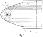
- FIGS. 1 to 4 show light modules 1 according to the invention according to a first, second and third embodiment.
- the light module 1 has a light source 2, which may be an LED, in particular a high-power LED, wherein the LED may have a single LED or an LED cluster.
- the luminous means 2 consists of a small point light source.
- the LED (s) used preferably has a typical diameter of about 2 to 40 mm. However, the invention is not limited thereto.
- the light module 1 has a light-directing element 3 for substantially parallel directed light guidance of the light emitted by the light source 2.
- the direction of the light emitted by the luminous means 2 is understood as meaning essentially the direction of light directed in parallel, so that the rays of the beam of light emitted by the luminous means 2 and directed by the light-directing element 3 are substantially parallel to one another (see, for example, FIGS FIG. 2 ).
- the light-guiding element 3 may be a reflector 31 such as a parabolic reflector. As in particular in FIG.
- the light-guiding element 3 may further comprise a reflector means 33 which is provided (here between the light source 2 and a defoaming tube 4 described below or on the side of the light-emitting means 2 facing the anti-glare tube 4) that the light components of the Illuminant 2 emitted light, which would not meet directly on the reflector (would), be redirected so that this light component is directed to the reflector to be influenced in a corresponding manner by this to the total (substantially parallel) directed light direction.
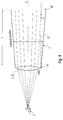
- the light-guiding element 3 can also have a particularly convex or concave lens optic 32 (see, for example, FIG Figures 3 and 4 ), by means of which a desired directional light control is achieved.
- the light-guiding element 3 may be formed integrally with the light-emitting means 2 as a light-emitting element; for example in the form of an LED module.
- the anti-dazzle tube 4 is preferably a "dark tube", which is preferably not illuminated by the light-emitting means 4.
- anti-dazzle tube is meant, in particular, a tube in which a user views the light module directly into the light only when viewed perpendicular to the main emission direction (ie, a dimming tube to avoid dazzling the user).
- the anti-dazzle tube 4 may have a round or polygonal, preferably hexagonal or rectangular, cross-section.
- the inner side or the inner jacket 40 of the anti-dazzle tube 4 is preferably non-reflective and / or light-absorbing.
- the side walls 43 of the anti-dazzle tube 4 preferably extend substantially parallel to the longitudinal axis S of the anti-glare tube 4 or the light emission direction. However, the anti-dazzle tube 4 can also expand substantially constantly away from the light-guiding element 3.
- the side walls 43 of the anti-dazzle tube 4 then preferably connect with the longitudinal axis S of the anti-dazzle tube 4 (eg the symmetry axis of the anti-dazzle tube 4) or the light emission direction (eg main emission direction of the light module 1) the same angle a as the widened light; For example, an angle a of less than or equal to 10 °, particularly preferably less than or equal to 5 °, most preferably of less than or equal to 2 °.
- the outermost light beam of an expanded light beam in this case preferably extends substantially parallel to the defibrillation tube wall; So inner wall or outer shell.
- the anti-dazzle tube 4 thus preferably has a shape tapering in the direction of the luminous means 2.
- Such a glare tube 4 is exemplary with a lens system 32 in FIG. 4 shown, wherein the light is emitted in such a directed manner by the light-guiding element 3 that preferably no light component of the light strikes the side walls 43 of the anti-dazzle tube 4.
- the light-guiding element 3 is preferably shaped accordingly and the anti-glare tube 4 has a correspondingly expanded shape, as shown by way of example in FIG FIG. 4 is shown. The widening is greater the closer the object to be irradiated to the light-emitting opening 42 is. Overall, however, preferably results in a substantially parallel light emission, as previously described.
- the light-directing element 3 in particular causes the light of the luminous means 2 to be emitted in such a direction that, if possible, it is emitted only in the desired direction and does not strike the anti-dazzle tube 4.
- the anti-dazzle tube 4 serves to shield the light or beam to be emitted laterally and to absorb light incident on the inner wall 40 as much as possible (ie, light portions which are not sufficiently directed).
- the directional light is emitted to the outside. Outwardly, this is understood to be outside of the light module 1, which may be, for example, that space in which an object to be irradiated is located.
- the anti-dazzle tube 4 preferably has a light emission opening 42 for this purpose. This can be located on a side facing away from the light-guiding element 3. The directed light is then emitted from the light module 1, ie, to the outside, via the light emission opening 42.
- a light coupling opening 41 may be provided on a side facing the light-guiding element 3.
- the preferably all-round side walls 43 of the anti-dazzle tube 4 extend.
- the light coupling opening 41 and light-emitting opening 42 preferably have the same geometry. However, it can also be provided that the light injection opening 41 and the light emission opening 42 have different geometries.
- the light-guiding element 3 may be formed integrally with the anti-glare tube 4 and thus practically “flowing" into the light-coupling opening 41 of the anti-glare tube 4.
- the anti-dazzle tube 4 can also be separated and, for example, also detachably connected, for example via a screw connection between the anti-dazzle tube 4 (for example in the region of the light injection opening 41) and the light-directing element 3, to the light-directing element 3.
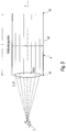
- the glare of the emitted light from the light module 1 to the outside preferably depends in particular on the ratio of average diameter D of the anti-dazzle tube 4 to the length L (see. FIGS. 1 . 3 and 4 ).
- the average diameter D corresponds to a circular cross-section of the anti-glare tube 4 the diameter of the circle. In cross-sections deviating from circular cross-sections, the average diameter results from an averaging of the radial distances or even the greatest radial distance of the side walls 43 with respect to the longitudinal axis S about the longitudinal axis S. Is the anti-dazzle tube 4 (also) formed widened, as in FIG.
- the average diameter is also shown as averaging of the mean diameter per cross-section in the longitudinal direction over the length L of the anti-glare tube 4. In practice, it has a particularly good glare at a ratio of average diameter D derblendungsrschreibe 4 to the length L of 1: 2, preferably at least 1: 5 result.
- the anti-glare effect depends in particular on the length L of the anti-dazzle tube 4, ie the longer the anti-dazzle tube 4, the clearer is the effect of glare reduction or the better the anti-glare effect.
- the diameter of the luminous means 2 or the light-guiding element 3 determines the required length L of the antiglare tube 4.
- the minimum diameter of the antiglare tube 4 is preferably determined in particular by the size of the luminous means 2. He corresponds to at least the size of the bulb 2; So with LEDs, for example, a diameter of about 2 to 40mm. Preferably, the diameter of the anti-dazzle tube 4 is not or not substantially greater than the (or the diameter of) the bulb (s). 2
- FIG. 5 is a lamp 100 in the execution example of an office lighting, here a floor lamp, which has an exemplary lighting system 10.
- the lighting system 10 has at least two light modules 1 according to the invention.
- the light modules 1 can be arranged by way of example in such a way that the directional light of at least a part of these light modules 1 is delivered tilted to one another.
- the light modules 1 are arranged such that the directional light of at least part of these light modules 1 is emitted substantially parallel to one another.
- the lighting system 10 consists of several light modules 1, which are arranged for example in the form of a matrix or a grid.
- the light modules 1 are preferably arranged in such a way that the directed light is imaged on an object 5 to be irradiated (here by way of example a table) as a homogeneous, coherent overall light surface 6.
- the total light area 6 may be in the shape of a circle or a circle segment.
- the total light surface 6 may also be any other shape, such as e.g. the shape of a polygon, in particular a quadrangle or hexagon.
- the directed light of a light module 1 can be imaged on an object 5 to be irradiated (here a table) as a single light surface 61 or as a projected light spot.
- the individual light surfaces 61 are imaged directly adjacent to each other, so that the individual light surfaces 61 do not essentially overlap or overlap a little.
- the light surfaces 61 thus form the (preferably continuous) total light surface 6 or a preferably homogeneous "patchwork" composed of the individual light surfaces 61.
- the shape of the light source 2, the light-directing element 3 and the anti-dazzle tube 4 of the light module 1 can be adapted such that the individual light surfaces 61 do not substantially overlap or overlap slightly to form the total light surface 6. As in FIG.
- the light surfaces 61 may have a quadrangular shape. As in FIG. 6
- the light surfaces 61 may also take the form of a polygon, in particular a hexagon (FIG. FIG. 6b ) and / or a circle or an ellipse ( FIG. 6a ) respectively.
- the shape of the light surface 61 should preferably be suitable for forming a homogeneous coherent total light surface 6 from the sum of the light surfaces 61.
- the light surface 61 corresponds to the cross-sectional shape of the respective anti-glare tube 4. That is, the cross-sectional shape of the respective anti-glare tube 4 forms the shape of the light surface 61.
- the total light surface 6 of the cross-sectional shape (at least a part) of the respective Entblendungsröhren 4 correspond.
- the luminaire 100 has a luminaire housing 101 which accommodates the light module (s) 1 or the lighting system 10.
- the luminaire housing 101 is shown here as a column, which takes up little space - so it is compact. Thus, the appearance of a corresponding lamp 100 can be improved over previously very large-scale solutions.
- the lamp 100 preferably further comprises a lamp base 102 to the lamp housing 101 of the lamp 100 on the floor / table / etc. to set up safely. It is also conceivable that the lamp base holding means (clamp or the like) has to attach the lamp 100 to an object.
- a part of the lamp housing 101, the defibrillation tube (s) 4 form.
- the anti-dazzle tubes 4 are formed as blind holes in the lamp housing 101. Light guide element 3 and light source 2 can then be used in the bottom of the blind hole. To fulfill the non-reflective or light-absorbing property, the part of the light housing 101 forming the anti-dazzle tube 4 can be correspondingly coated.
Description
- Die Erfindung betrifft ein Lichtmodul, welches eine gerichtete Lichtabgabe bereitstellt, ein Leuchtensystem mit den Lichtmodulen sowie eine Leuchte mit Lichtmodul bzw. Leuchtensystem.
- Aus dem Stand der Technik sind Leuchtenanordnungen bzw. Leuchtensysteme bekannt, welche eine flächenförmige Lichttechnik mit sich meist horizontal erstreckender, großer Lichtaustrittsfläche verwenden und welche hoch an einer Säule befestigt sind und von dieser abstehen bzw. herausragen. Dies dient dazu, den Arbeitsbereich (z.B. einen Tisch) möglichst homogen auszuleuchten und gleichzeitig den Nutzer möglichst wenig zu blenden. Hierfür ist insbesondere die Norm DIN EN 12.464-1 von Relevanz. Aus dem Stand der Technik bekannte Lösungen verwenden insbesondere verschiedene Lichtleitende oder -brechende oder -streuende Kunststoffplatten (z.B. Microprismenplatten; Micro-Pyramiden-Optiken; Lichtleiterplatten mit einseitig gelaserten Strukturen; seitliches Einkoppeln, um flacher konstruieren zu können; Diffusorplatten). Ebenso sind aus dem Stand der Technik Strahler (Spots) bekannt: Diese bestehen aus einem einzigen Leuchtmittel (z.B. einer Glühlampe) und einem einzigen Reflektor. Nachtteilig bei diesen Leuchtenanordnungen ist in der Regel, dass sie bei kleinem oder teilweise bei Stehleuchten auch recht großem Leuchtenkopf eine breite Lichtabgabe bereitstellen und somit eine hohe Blendwirkung auch für den Benutzer haben, da das Licht meist nach dem Verlassen des Leuchtmittels recht breit gestreut abgegeben wird. Eine derartige Leuchtenanordnung ist beispielsweise aus der Druckschrift
DE 698 24 669 T2 bekannt. -
US2014/299897A1 ,DE3432041A1 ,EP2511595A1 ,WO2013/142437A1 undUS3671735A offenbaren Leuchtenanordnungen. - Ausgehend von dem bekannten Stand der Technik ist es nunmehr eine Aufgabe der vorliegenden Erfindung, die Blendwirkung der aus dem Stand der Technik bekannten Leuchtenanordnungen zu reduzieren; bestenfalls auf ein minimales Maß, so dass lediglich bei direktem Blick auf das Leuchtmittel das Licht auf den Betrachter fällt.
- Diese Aufgabe wird durch den Gegenstand der unabhängigen Ansprüche gelöst. Die abhängigen Ansprüche bilden den zentralen Gedanken der Erfindung in besonders vorteilhafter Weise weiter.
- Zur Lösung dieser Aufgabe betrifft die Erfindung eine Leuchte aufweisend ein Leuchtensystem, mit zumindest zwei Lichtmodulen, wobei das jeweilige Lichtmodul aufweist: ein Leuchtmittel, ein Lichtlenkelement zur im Wesentlichen parallel gerichteten Lichtlenkung des von dem Leuchtmittel abgegebenen Lichts, und eine sich von dem Lichtlenkelement im Wesentlichen parallel in Lichtabgaberichtung des Lichtlenkelements weg erstreckende Entblendungsröhre, über die das gerichtete Licht nach außen abgegeben wird.
- Unter "im Wesentlichen parallel" wird im Rahmen der Erfindung verstanden, dass das gerichtete Licht bzgl. der Hauptabstrahlrichtung bzw. der Innenwand oder Außenhülle (ggf. auch der Längsachse / Symmetrieachse) der Entblendungsröhre parallel ausgerichtet ist.
- Durch das erfindungsgemäße Lichtmodul wird effektiv verhindert, dass das Licht des Leuchtmittels breit (bspw. kugelförmig) streut und dadurch einen Nutzer blendet. Das erfindungsgemäße Lichtmodul bewirkt vielmehr, dass das Licht gerichtet und vorzugsweise nahezu parallel aus dem Lichtmodul austritt, sodass eine Blendwirkung auf einen Nutzer erst dann eintritt, wenn dieser in Achsrichtung (Hauptabstrahlrichtung bzw. Lichtabgaberichtung) des nach außen abgegeben Lichts des Lichtmoduls schaut. Darüber hinaus wird durch das erfindungsgemäße Lichtmodul eine blendärmere, effizientere, und kleinere normgerechte Leuchtenanordnung bereitgestellt. Dies kommt sowohl einem moderneren Design des Lichtmoduls / der Leuchtenanordnung als auch den mit dem Lichtmodul / der Leuchtenanordnung verbundenen Kosten (insbesondere Herstellungs- und Montagekosten) zugute. Das Lichtmodul kann besonders kompakt und platzsparend ausgebildet werden, wodurch insgesamt kleinere (Steh-)Leuchten konstruiert werden können.
- Vorzugsweise weist die Entblendungsröhre eine Lichteinkopplungsöffnung auf einer dem Lichtlenkelement zugewandten Seite, in welche das durch das Lichtlenkelement gerichtete Licht in die Entblendungsröhre eingekoppelt wird (also in diese eintritt), und eine Lichtabgabeöffnung auf einer dem Lichtlenkelement abgewandten Seite, über welche das gerichtete Licht aus dem Lichtmodul bzw. der Leuchtenanordnung abgegeben wird, auf. Die Entblendungsröhre ist somit bevorzugt (um die Längsachse herum) umfangsseitig geschlossen und ist an ihren beiden Enden in Längsrichtung gesehen offen bzw. weist an diesen Enden jeweils eine entsprechende Öffnung auf. Die Entblendungsröhre hat somit bevorzugt eine Rohrform.
- In die Entblendungsröhre über die Lichteinkoppelöffnung eingekoppeltes Licht kann somit gezielt aus der Lichtabgabeöffnung ausgegeben werden, sodass die Lichtausgabe des Lichtmoduls gezielt z.B. auf ein zu bestrahlendes Objekt ausgerichtet werden kann. Durch die Rohrform wird eine höchst effektive Entblendung ermöglicht, da sie in der Ausgestaltung einfach ist und in der Praxis (bspw. wegen Staub, Toleranzen) gleichzeitig einen Lichtaustritt von nicht-parallel gerichteten Lichtanteilen sicher unterdrücken kann.
- Die Entblendungsröhre kann einen runden (z.B. Hohlzylinder) oder mehreckigen, vorzugsweise einen sechseckigen oder rechteckigen, Querschnitt aufweisen.
- Dadurch wird eine Entblendungsröhre bereitgestellt, welche einen hohen Grad an gestalterischer Freiheit erlaubt. Zudem ist eine entsprechende Entblendungsröhre durch ihre durch den Querschnitt bedingte strukturelle Form insbesondere vorteilhaft für ihre Fertigung und ihre Montage in dem Lichtmodul bzw. der Leuchtenanordnung. So können bspw. Entblendungsröhren geschaffen werden, welche beliebig und vorzugsweise umfangsseitig lückenlos miteinander bereitgestellt werden können.
- Vorzugsweise ist die Entblendungsröhre wenigstens auf ihrer Innenseite nicht-reflektierend und/oder lichtabsorbierend ausgebildet.
- Durch die nicht-reflektierende Eigenschaft der Innenseite der Entblendungsröhre kann insbesondere verhindert werden, dass in die Entblendungsröhre eingekoppeltes im Wesentlichen nicht-parallel (bspw. zur Entblendungsröhrenaußenhülle) gerichtetes und auf die Innenseite der Entblendungsröhre treffendes Licht reflektiert wird und daraufhin in eine die Achsrichtung des nach außen abgegeben Lichts abweichende Richtung abgegeben wird und somit einen Nutzer blenden kann. Die Lichtabsorption der Innenseite (d.h. die Energie des auf die Innenseite treffenden, im Wesentlichen nicht-parallel gerichteten Lichts wird in Wärme umgewandelt, indem die Innenseite der Entblendungsröhre sich erwärmt) bewirkt ebenfalls, dass nur entlang der Richtung der Innenseite der Entblendungsröhre gerichtetes Licht aus dem Lichtmodul nach außen abgegeben wird. In jedem Fall wird dadurch die Wirkung der Entblendung des Lichtmoduls bzw. der Leuchtenanordnung erhöht.
- Die Seitenwände der Entblendungsröhre können sich im Wesentlichen parallel zu der Längsachse der Entblendungsröhre bzw. der Lichtabgaberichtung (Achsrichtung des Lichts) erstrecken.
- Durch diese vorteilhafte Erstreckung der Seitenwände kann ein positiver Einfluss auf die Entblendung bewirkt werden, da bevorzugt nur parallel gerichtete Lichtanteile die Entblendungsröhre verlassen. Die Längsachse der Entblendungsröhre ist dabei bevorzugt koaxial zur Hauptabstrahlrichtung bzw. zur Lichtabgaberichtung bzw. Achsrichtung des von dem Lichtlenkelement gerichtet abgegebenen Lichts.
- Vorzugsweise weitet sich die Entblendungsröhre von dem Lichtlenkelement weg im Wesentlichen konstant auf, wobei die Seitenwände der Entblendungsröhre mit der Längsachse der Entblendungsröhre bzw. der Lichtabgaberichtung einen Winkel in Abhängigkeit zum Abstand der zu beleuchtenden Fläche aufweisen (bevorzugt denselben Winkel einschließen, wie das aufgeweitete Lichtbündel); beispielsweise wenn eine zu beleuchtende Fläche recht nah vor der Entblendungsröhre angeordnet ist, um bei Verwendung mehrerer Entblendungsröhren eine zusammenhängende Gesamtlichtfläche zu schaffen, wie dies im Weiteren auch noch beschrieben ist. Je näher die zu beleuchtende Fläche der Entblendungsröhre ist, desto mehr kann also bevorzugt das Strahlenbündel aufgeweitet gerichtet abgegeben werden.
- Das Verhältnis von mittlerem Durchmesser der Entblendungsröhre zu deren Länge beträgt vorzugsweise wenigstens 1:2, besonders vorzugsweise wenigstens 1:5.
- Unter "mittlerem Durchmesser" wird im Rahmen der Erfindung derjenige Durchmesser verstanden, welcher sich in radialer Richtung gesehen gemittelt um die Längsachse der Entblendungsröhre herum sowie über die Länge der Entblendungsröhre gesehen ergibt. Bei den angegebenen Verhältnissen hat sich in der Praxis eine besonders gute Entblendung des Lichtmoduls bzw. der Leuchtenanordnung ergeben. Grundsätzlich ist die Entblendung besser, je länger die Entblendungsröhre ist, wobei dieser Effekt ab einem Verhältnis von 1:5 mit weiter steigender Länge nur noch geringfügig verbessert wird.
- Das Lichtlenkelement ist ein Reflektor, wie bspw. ein Parabolreflektor, und/oder, in einer nicht beanspruchte Darstellung, eine Linsenoptik. Durch vorgenannte Lichtlenkelemente kann auf besonders einfache Weise eine parallel gerichtete Lichtlenkung des von dem Leuchtmittel abgegebenen Lichts erzielt werden.
- Auf der der Entblendungsröhre zugewandten Seite des Leuchtmittels kann ein Reflektormittel vorgesehen sein, welches derart ausgebildet und angeordnet ist, um die Lichtanteile des vom Leuchtmittel abgegebenen Lichts, welche (ohne Vorhandensein des Reflektormittels) nicht direkt auf den Reflektor treffen (würden), derart umzulenken, dass dieser Lichtanteil auf den Reflektor zur gerichteten Lichtabgabe gelenkt wird.
- Auf diese Weise kann alles vom Leuchtmittel abgestrahlte Licht zur gerichteten Lichtabgabe verwendet und somit die Effizienz des Lichtmoduls bzw. der Leuchtenanordnung nochmals erhöht werden.
- Das Leuchtmittel kann eine LED, insbesondere eine Hochleistungs-LED, sein, wobei die LED eine einzelne LED oder ein LED-Cluster aufweist. Die verwendeten LEDs haben bevorzugt eine Größe bzw. einen typischen Durchmesser von ca. 2 bis 40mm. Die Entblendungsröhre hat demnach einen Mindestdurchmesser, welcher wenigstens der Größe bzw. dem Durchmesser des Leuchtmittels bzw. des Leuchtmittel-Moduls entspricht. Bevorzugt ist der Durchmesser der Entblendungsröhre dabei nicht oder nicht wesentlich größer als das Leuchtmittel selbst. "Nicht oder nicht wesentlich" bedeutet dabei, dass der Durchmesser der Entblendungsröhre bevorzugt wenigstens einen Durchmesser hat, bei dem das erfindungsgemäße Lichtmodul funktionsgemäß betrieben werden kann, besonders bevorzugt aber im Durchmesser nicht größer ist, als der zum (gewünschten) Betrieb erforderliche Mindestdurchmesser.
- Diese Leuchtmittel eignen sich besonders gut für das Lichtmodul bzw. die Leuchtenanordnung, da diese sowohl preisgünstig als auch effizient sind, insbesondere hinsichtlich der Kosten und Lumen pro Watt.
- Vorzugsweise ist das Lichtlenkelement integral mit dem Leuchtmittel als Leuchtelement, insbesondere als LED-Modul, ausgebildet.
- Die integrale und insbesondere modulare Ausbildung bewirkt eine Reduktion des Montageaufwands des Lichtmoduls bzw. der Leuchtenanordnung, was wiederum dem Kostenaufwand zugutekommt.
- Durch das erfindungsgemäße Leuchtensystem werden die zuvor bzgl. des einzelnen Lichtmoduls beschriebenen Vorteile auf ein entsprechendes System übertragen, mit dem in einfacher Weise auch eine große Fläche bei maximaler Entblendung ausgestrahlt bzw. gerichtet beleuchtet werden kann. Dabei wird insbesondere vorteilhaft bewirkt, dass die Leuchtdichte je Lichtmodul bzw. Leuchtmittel reduziert wird, um z.B. ein Objekt zu bestrahlen. Somit wird ein aus mehreren kleinen "Punktlichtquellen" bestehendes System geschaffen, welches durch die Summe der "Punktlichtquellen" geeignet ist, eine Fläche auszuleuchten. Durch die kompakte Ausgestaltung der Lichtmodule können folglich insgesamt platzsparendere Systeme geschaffen werden. Auch ist es denkbar, durch eine Matrix-artige Anordnung der Lichtmodule und somit der Leuchtmittel, anwendungsspezifische Lichtszenarien zu verwirklichen; bspw. einstellbare Lichtschwerpunkte auf einer Arbeitsfläche. Hierzu sind die einzelnen Lichtmodule bspw. unabhängig voneinander ansteuerbar (bspw. dimmbar bzw. betreibbar).
- Vorzugsweise sind in dem Leuchtensystem wenigstens zwei, mehrere oder alle der Lichtmodule derart angeordnet, dass das gerichtete Licht dieser Leuchtanordnungen im Wesentlichen parallel zueinander abgegeben wird oder in einem Winkel in Abhängigkeit zum Abstand der zu beleuchtenden Fläche austritt, also geringfügig divergierend abgegeben wird. Dabei sind bevorzugt die entsprechenden Achsrichtungen bzw. Lichtabgaberichtungen bzw. Hauptabstrahlrichtungen parallel zueinander ausgerichtet.
- Durch diese Anordnung der Lichtmodule kann in bevorzugter und einfacher Weise eine zusammenhängende Lichtfläche gebildet werden, um z.B. ein größeres Objekt zu bestrahlen, welches mit nur einem erfindungsgemäßen Lichtmodul nicht bei gleicher Entblendung komplett bestrahlt werden könnte. Da insbesondere ein Lichtmodul nur einen kleinen Teil des zu bestrahlenden Objekts bestrahlt, ist die Schattenwirkung aufgrund des gerichteten Lichts eher scharfkantig und nicht diffus, wie es von bekannten Leuchtensystemen aus dem Stand der Technik bekannt ist. Zudem können Lichtschwerpunkte auf dem zu bestrahlendem Objekt eingestellt werden, d.h. es können z.B. anwendungsspezifische Lichtszenarien ermöglicht werden.
- Die Lichtmodule können derart angeordnet sein, dass das gerichtete Licht auf einem zu bestrahlenden Objekt als homogene zusammenhängende Gesamtlichtfläche abgebildet wird.
- Durch die abgebildete homogen zusammenhängende Gesamtlichtfläche auf dem zu bestrahlendem Objekt ergibt sich insbesondere eine optisch ansprechende - da gleichmäßig ausgeleuchtete - und großflächige Beleuchtung des zu bestrahlenden Objekts bei maximaler Entblendung.
- Vorzugsweise sind die Lichtmodule derart angeordnet, dass das gerichtete Licht jeder der Lichtmodule auf einem zu bestrahlenden Objekt als einzelne Lichtfläche abgebildet wird, wobei die einzelnen Lichtflächen direkt aneinander angrenzend abgebildet werden, so dass sich die einzelnen Lichtflächen im Wesentlichen nicht überschneiden.
- Unter "im Wesentlichen nicht überschneiden" wird im Rahmen der Erfindung verstanden, dass die Lichtflächen bevorzugt direkt angrenzend aneinander anliegen, so dass keine Dunkelzonen gebildet werden, wobei bei "gerade keine Dunkelzonen mehr" bildender Ausleuchtung sich eventuell (aufgrund der geometrischen Form der Lichtflecken) ergebende Überlappungen eine entsprechende Überschneidung bilden können. Durch diese Anordnung der Lichtflächen der einzelnen Lichtmodule kann auf besonders effiziente Weise ein Objekt bestrahlt werden, da bevorzugt (im Wesentlichen) keine Teilfläche des zu bestrahlenden Objekts von mehr als einem Lichtmodul bestrahlt wird.
- Die Lichtflächen und/oder die Gesamtlichtfläche kann die Form eines Mehrecks, insbesondere eines Vierecks oder Sechsecks, und/oder Kreises aufweisen.
- Diese Formen eignen sich in besonders vorteilhafter Weise zur Bildung einer homogen zusammenhängenden Gesamtlichtfläche bzw. zur Bildung einer Gesamtlichtfläche gebildet aus mehreren direkt aneinander angrenzenden Lichtflächen. Bevorzugt treten maximal Doppelschatten an den Überlappzonen auf und keine Mehrfachschatten, wie sonst bei multiplen Lichtquellen üblich.
- Die Lichtflächen und/oder die Gesamtlichtfläche der Querschnittsform kann/können der jeweiligen Entblendungsröhre entsprechen.
- Die sowieso bereits vorhandene Struktur der Entblendungsröhre kann somit zur Bildung der Lichtflächen und/oder entsprechend zusammenhängenden Gesamtlichtfläche genutzt werden. Die Anzahl der Teile und der Montageaufwand können somit besonders einfach gering gehalten werden.
- Die Leuchte ist insbesondere eine Steh- oder Tischleuchte, wobei diese wenigstens eine der vorgenannten Lichtmodule oder Leuchtensysteme aufweist. Die Leuchte weist ein Leuchtengehäuse auf, welches das (die) Lichtmodul(e) bzw. das (die) Leuchtensystem(e) aufnimmt. Das Leuchtengehäuse kann bevorzugt als Säule ausgebildet sein. Das Leuchtengehäuse kann bspw. mittels eines Leuchtenfußes zur Bildung einer Steh- oder Tischleuchte aufgestellt oder durch entsprechende Haltemittel an Objekten befestigt werden. Ein Teil des Leuchtengehäuses kann die Entblendungsröhre(n) bilden, vorzugsweise durch Öffnungen bspw. in Form von Sacklochbohrung(en), in welchen jeweils ein Lichtlenkelement und ein Leuchtmittel aufgenommen ist. Die Lichtmodule der Leuchte bzw. des Leuchtensystems sind wenigstens teilweise (also einzeln oder in Gruppen) unabhängig voneinander ansteuerbar; bspw. dimmbar oder betreibbar oder auch auf andere Weise einstellbar (bspw. in ihrer Farbe einstellbar).
- Unter Anderem sind durch die erfindungsgemäße Lösung somit Steh- oder Tischleuchten denkbar, bei denen das Licht nicht in einem Leuchtenkopf erzeugt wird, sondern direkt aus dem Leuchtengehäuse (bspw. in Form einer Säule) kommt. Somit weist die Leuchte eine vorzugsweise senkrechte Säule auf, in der das (die) Lichtmodul(e) vorgesehen sind. Auf einen großflächigen Leuchtenkopf kann somit verzichtet werden. Bei integraler Ausbildung der Entblendungsröhre mit/in dem Leuchtengehäuse können ferner die Teilezahl und auch Herstellungs- und Montageaufwand reduziert werden.
- Die Erfindung wird nachfolgend anhand der Zeichnungen der begleitenden Figuren näher erläutert. Gleiche Bezugszeichen werden für die gleichen Merkmale verwendet. Darin zeigt:
- Figur 1
- eine seitliche Schnittansicht des erfindungsgemäßen Lichtmoduls gemäß einem ersten Ausführungsbeispiel,
- Figur 2
- eine Detailansicht des erfindungsgemäßen Lichtmoduls gemäß dem ersten Ausführungsbeispiel,
- Figur 3
- eine seitliche Schnittansicht des erfindungsgemäßen Lichtmoduls gemäß einem zweiten Ausführungsbeispiel,
- Figur 4
- eine seitliche Schnittansicht des erfindungsgemäßen Lichtmoduls gemäß einem dritten Ausführungsbeispiel,
- Figur 5
- eine erfindungsgemäßes Leuchtensystem gemäß einem ersten Ausführungsbeispiel, und
- Figur 6
- Draufsichten beispielhafter Lichtflächen bzw. Gesamtlichtflächen eines erfindungsgemäßen Leuchtensystems.
-
Figuren 1 bis 4 zeigen erfindungsgemäße Lichtmodule 1 gemäß einem ersten, zweiten und dritten Ausführungsbeispiel. - Das Lichtmodul 1 weist ein Leuchtmittel 2 auf, welches eine LED, insbesondere eine Hochleistungs-LED, sein kann, wobei die LED eine einzelne LED oder ein LED-Cluster aufweisen kann. Vorzugsweise besteht das Leuchtmittel 2 aus einer kleinen Punktlichtquelle. Die verwendete(n) LED(s) hat (haben) bevorzugt einen typischen Durchmesser von ca. 2 bis 40mm. Die Erfindung ist hierauf jedoch nicht beschränkt.
- Ferner weist das Lichtmodul 1 ein Lichtlenkelement 3 zur im Wesentlichen parallel gerichteten Lichtlenkung des von dem Leuchtmittel 2 abgegebenen Lichts auf. Unter im Wesentlichen parallel gerichteter Lichtlenkung wird hierbei insbesondere die Lenkung des von dem Leuchtmittel 2 abgegebenen Lichts verstanden, sodass die Strahlen des Strahlenbündels des von dem Leuchtmittel 2 abgegebenen und durch das Lichtlenkelement 3 gerichteten Lichts im Wesentlichen parallel zueinander sind (siehe z.B.
Figur 2 ). Wie in denFiguren 1 und2 dargestellt, kann das Lichtlenkelement 3 ein Reflektor 31 wie bspw. ein Parabolreflektor sein. Wie insbesondere inFigur 2 zu erkennen ist, kann dabei das Lichtlenkelement 3 weiterhin ein Reflektormittel 33 aufweisen, welches derart (hier zwischen Leuchtmittel 2 und einer im weiteren beschriebenen Entblendungsröhre 4 bzw. auf der der Entblendungsröhre 4 zugewandten Seite des Leuchtmittels 2) vorgesehen ist, dass die Lichtanteile des vom Leuchtmittel 2 abgegebenen Lichts, welche nicht direkt auf den Reflektor treffen (würden), derart umgelenkt werden, dass auch dieser Lichtanteil auf den Reflektor gelenkt wird, um in entsprechender Weise von diesem zur insgesamt (im Wesentlichen parallel) gerichteten Lichtlenkung beeinflusst zu werden. Zusätzlich oder alternativ kann das Lichtlenkelement 3 auch eine insbesondere konvexe oder konkave Linsenoptik 32 (siehe z.B.Figuren 3 und4 ) aufweisen, mittels denen eine gewünschte gerichtete Lichtlenkung erzielt wird. Bevorzugt kann das Lichtlenkelement 3 integral mit dem Leuchtmittel 2 als Leuchtelement ausgebildet sein; bspw. in Form eines LED-Moduls. - Von dem Lichtlenkelement 3 erstreckt sich im Wesentlichen parallel in Lichtabgaberichtung des Lichtlenkelements 3 eine Entblendungsröhre 4 weg. Die Entblendungsröhre 4 ist vorzugsweise eine "dunkle Röhre", welche von dem Leuchtmittel 4 bevorzugt nicht angeleuchtet wird. Unter "Entblendungsröhre" ist insbesondere eine Röhre gemeint, bei der ein Nutzer bestenfalls nur bei Blick senkrecht zur Hauptabstrahlrichtung auf das Lichtmodul direkt in das Licht blickt (d.h. ein Abblendtubus, um ein Blenden des Nutzers zu vermeiden). Die Entblendungsröhre 4 kann einen runden oder mehreckigen, vorzugsweise sechseckigen oder rechteckigen, Querschnitt aufweisen. Zudem ist vorzugsweise die Innenseite bzw. der Innenmantel 40 der Entblendungsröhre 4 nicht-reflektierend und/oder lichtabsorbierend ausgebildet. Dies kann bspw. dadurch erreicht werden, indem die Innenseite entspiegelt und/oder dunkel (bspw. schwarz) ausgebildet ist. Die Seitenwände 43 der Entblendungsröhre 4 erstrecken sich vorzugsweise im Wesentlichen parallel zu der Längsachse S der Entblendungsröhre 4 bzw. der Lichtabgaberichtung. Die Entblendungsröhre 4 kann sich aber auch von dem Lichtlenkelement 3 weg im Wesentlichen konstant aufweiten. Die Seitenwände 43 der Entblendungsröhre 4 schließen dann vorzugsweise mit der Längsachse S der Entblendungsröhre 4 (z.B. die Symmetrieachse der Entblendungsröhre 4) oder der Lichtabgaberichtung (z.B. Hauptabstrahlrichtung des Lichtmoduls 1) denselben Winkel a wie das aufgeweitete Licht ein; beispielsweise einen Winkel a von kleiner oder gleich 10°, besonders vorzugsweise kleiner oder gleich 5°, ganz besonders bevorzugt von kleiner oder gleich 2° ein. Der äußerste Lichtstrahl eines aufgeweiteten Lichtbündels verläuft hierbei bevorzugt im Wesentlichen parallel zur Entblendungsröhrenwand; also Innenwand bzw. Außenhülle. Die Entblendungsröhre 4 weist somit vorzugweise eine in Richtung des Leuchtmittels 2 hin verjüngende Form auf. Eine derartige Entblendungsröhre 4 ist beispielhaft mit einer Linsenoptik 32 in
Figur 4 abgebildet, wobei das Licht derart durch das Lichtlenkelement 3 gerichtet abgegeben wird, dass bevorzugt kein Lichtanteil des Lichts auf die Seitenwände 43 der Entblendungsröhre 4 trifft. Ist ein aufgeweitetes Strahlenbüdel gefordert (bspw. weil die zu beleuchtende Fläche nahe an dem Lichtmodul 1 angeordnet ist), so ist bevorzugt das Lichtlenkelement 3 entsprechend ausgeformt und die Entblendungsröhre 4 weist eine sich entsprechend aufgeweitete Form auf, wie sie beispielhaft inFigur 4 abgebildet ist. Die Aufweitung ist umso größer, je näher das zu bestrahlende Objekt der Lichtabgabeöffnung 42 ist. Insgesamt ergibt sich bevorzugt jedoch eine im Wesentlichen parallel Lichtabgabe, wie zuvor bereits beschrieben. - Wie aus
Figuren 1 bis 4 ersichtlich, bewirkt das Lichtlenkelement 3 insbesondere, dass das Licht des Leuchtmittels 2 derart gerichtet abgegeben wird, dass es möglichst nur in die gewünschte Richtung abgegeben wird und nicht auf die Entblendungsröhre 4 trifft. Die Entblendungsröhre 4 wiederum dient dazu, das gerichtet abzugebende Licht bzw. Strahlenbündel seitlich abzuschirmen und gegebenenfalls auf die Innenwand 40 treffendes Licht (also nicht ausreichend gerichtete Lichtanteile) weitestgehend zu absorbieren. - Über die Entblendungsröhre 4 wird das gerichtete Licht nach außen abgegeben. Nach außen versteht sich hierbei als außerhalb des Lichtmoduls 1, was z.B. jener Raum sein kann, in dem sich ein zu bestrahlendes Objekt befindet. Vorzugsweise weist die Entblendungsröhre 4 hierzu eine Lichtabgabeöffnung 42 auf. Diese kann sich auf einer dem Lichtlenkelement 3 abgewandten Seite befinden. Über die Lichtabgabeöffnung 42 wird dann das gerichtete Licht aus dem Lichtmodul 1, d.h. nach außen, abgegeben. Zur Einkopplung des Lichts in die Entblendungsröhre 4 kann eine Lichteinkopplungsöffnung 41 auf einer dem Lichtlenkelement 3 zugewandten Seite vorgesehen sein. Zwischen der Lichteinkopplungsöffnung 41 und Lichtabgabeöffnung 42 erstrecken sich die vorzugsweise ringsum geschlossenen Seitenwände 43 der Entblendungsröhre 4. Die Lichteinkopplungsöffnung 41 und Lichtabgabeöffnung 42 weisen vorzugsweise dieselbe Geometrie auf. Es kann jedoch auch vorgesehen sein, dass Lichteinkopplungsöffnung 41 und Lichtabgabeöffnung 42 unterschiedliche Geometrien aufweisen. Wie in den
Figuren 1 und2 dargestellt, kann das Lichtlenkelement 3 integral mit der Entblendungsröhre 4 ausgebildet sein und somit praktisch "fließend" in die Lichteinkopplungsöffnung 41 der Entblendungsröhre 4 übergehen. Die Entblendungsröhre 4 kann jedoch auch separat und bspw. ferner lösbar, z.B. über eine Schraubverbindung zwischen Entblendungsröhre 4 (bspw. im Bereich der Lichteinkopplungsöffnung 41) und Lichtlenkelement 3, mit dem Lichtlenkelement 3 verbunden sein. - Die Entblendung des von dem Lichtmodul 1 nach außen abgegebenen Lichts hängt bevorzugt insbesondere von dem Verhältnis von mittlerem Durchmesser D der Entblendungsröhre 4 zu deren Länge L ab (vgl.
Figuren 1 ,3 und4 ). Der mittlere Durchmesser D entspricht bei kreisrundem Querschnitt der Entblendungsröhre 4 dem Durchmesser des Kreises. Bei von kreisrunden Querschnitten abweichenden Querschnitten ergibt sich der mittlere Durchmesser aus einer Mittelung der radialen Abstände oder auch dem größten radialen Abstand der Seitenwände 43 bzgl. der Längsachse S um die Längsachse S herum. Ist die Entblendungsröhre 4 (zudem) aufgeweitet ausgebildet, wie inFigur 4 gezeigt, so ergibt sich der mittlere Durchmesser ferner aus der Mittelung der mittleren Durchmesser je Querschnitt in Längsrichtung über die Länge L der Entblendungsröhre 4 gesehen. In der Praxis hat sich dabei eine besonders gute Entblendung bei einem Verhältnis von mittlerem Durchmesser D der Entblendungsröhre 4 zu deren Länge L von 1:2, vorzugsweise wenigstens 1:5 ergeben. Die Entblendungswirkung hängt hierbei insbesondere von der Länge L der Entblendungsröhre 4 ab, d.h. je länger die Entblendungsröhre 4 ist, desto deutlicher ist der Effekt der Entblendung sichtbar bzw. desto besser ist die Entblendungswirkung. Zudem bestimmt insbesondere der Durchmesser des Leuchtmittels 2 bzw. des Lichtlenkelements 3 die erforderliche Länge L der Entblendungsröhre 4. Der Mindestdurchmesser der Entblendungsröhre 4 wird bevorzugt insbesondere durch die Größe des Leuchtmittels 2 bestimmt. Er entspricht dabei wenigstens der Größe des Leuchtmittels 2; also bei LEDs beispielsweise einem Durchmesser von ca. 2 bis 40mm. Bevorzugt ist der Durchmesser der Entblendungsröhre 4 nicht oder nicht wesentlich größer als das (bzw. der Durchmesser des) Leuchtmittel(s) 2. - In
Figur 5 ist eine Leuchte 100 in der Ausführung z.B. einer Bürobeleuchtung, hier einer Stehleuchte, welche ein beispielhaftes Leuchtensystem 10 aufweist. Das Leuchtensystem 10 weist zumindest zwei erfindungsgemäße Lichtmodule 1 auf. Wie abgebildet können die Lichtmodule 1 beispielhaft derart angeordnet sein, dass das gerichtete Licht wenigstens eines Teils dieser Lichtmodule 1 verkippt zueinder abgegeben wird. Es kann jedoch auch vorgesehen sein, dass die Lichtmodule 1 derart angeordnet sind, dass das gerichtete Licht wenigstens eines Teils dieser Lichtmodule 1 im Wesentlichen parallel zueinander abgegeben wird. Vorzugsweise besteht das Leuchtensystem 10 aus mehreren Lichtmodulen 1, welche beispielsweise in Form einer Matrix bzw. eines Rasters angeordnet sind. - Vorzugsweise sind die Lichtmodule 1 derart angeordnet, dass das gerichtete Licht auf einem zu bestrahlenden Objekt 5 (hier beispielhaft ein Tisch) als homogene zusammenhängende Gesamtlichtfläche 6 abgebildet wird. Wie abgebildet, kann die Gesamtlichtfläche 6 die Form eines Kreises bzw. eines Kreissegments aufweisen. Die Gesamtlichtfläche 6 kann auch jede andere Form aufweisen, wie z.B. die Form eines Mehrecks, insbesondere eines Vierecks oder Sechsecks.
- Das gerichtete Licht eines Lichtmoduls 1 kann auf einem zu bestrahlenden Objekt 5 (hier ein Tisch) als einzelne Lichtfläche 61 bzw. als projizierter Lichtfleck abgebildet werden. Vorzugsweise werden die einzelnen Lichtflächen 61 direkt aneinander angrenzend abgebildet, sodass sich die einzelnen Lichtflächen 61 im Wesentlichen nicht überschneiden bzw. wenig überlappen. Die Lichtflächen 61 bilden somit die (bevorzugt zusammenhängende) Gesamtlichtfläche 6 bzw. einen vorzugsweise homogenen "Flickenteppich" zusammengesetzt aus den einzelnen Lichtflächen 61. Insbesondere können die Form des Leuchtmittels 2, des Lichtlenkelements 3 und der Entblendungsröhre 4 des Lichtmoduls 1 derart angepasst werden, dass sich die einzelnen Lichtflächen 61 im Wesentlichen nicht überschneiden bzw. wenig überlappen, um die Gesamtlichtfläche 6 zu bilden. Wie in
Figur 5 oder 6c abgebildet, können die Lichtflächen 61 eine viereckige Form aufweisen. Wie inFigur 6 abgebildet, können die Lichtflächen 61 auch die Form eines Mehrecks, insbesondere eines Sechsecks (Figur 6b ) und/oder eines Kreises bzw. einer Ellipse (Figur 6a ) aufweisen. Die Form der Lichtfläche 61 sollte sich bevorzugt dazu eignen, dass aus der Summe der Lichtflächen 61 eine homogene zusammenhängende Gesamtlichtfläche 6 gebildet wird. Vorzugsweise entspricht die Lichtfläche 61 der Querschnittsform der jeweiligen Entblendungsröhre 4. D.h. die Querschnittsform der jeweiligen Entblendungsröhre 4 bildet die Form der Lichtfläche 61. Zudem kann auch die Gesamtlichtfläche 6 der Querschnittsform (wenigstens eines Teils) der jeweiligen Entblendungsröhren 4 entsprechen. - Die Leuchte 100 weist ein Leuchtengehäuse 101 auf, welches das (die) Lichtmodul(e) 1 bzw. das Leuchtensystem 10 aufnimmt. Das Leuchtengehäuse 101 ist hier als Säule dargestellt, welche wenig Platz beansprucht - also kompakt ausgebildet ist. Somit kann das Erscheinungsbild einer entsprechenden Leuchte 100 gegenüber bisher sehr großflächigen Lösungen verbessert werden. Die Leuchte 100 weist bevorzugt ferner einen Leuchtenfuß 102 auf, um das Leuchtengehäuse 101 der Leuchte 100 auf dem Boden/Tisch/etc. sicher aufzustellen. Es ist auch denkbar, dass der Leuchtenfuß Haltemittel (Klemme o.ä.) aufweist, um die Leuchte 100 an einem Objekt zu befestigen. Vorzugsweise kann ein Teil des Leuchtengehäuses 101 die Entblendungsröhre(n) 4 bilden. Beispielsweise sind die Entblendungsröhren 4 als Sacklochbohrungen in dem Leuchtengehäuse 101 ausgebildet. Lichtlenkelement 3 und Leuchtmittel 2 können dann in dem Grund des Sacklochs eingesetzt sein. Zur Erfüllung der nicht-reflektierenden bzw. Licht-absorbierenden Eigenschaft kann der die Entblendungsröhre 4 bildende Teil des Leuchtengehäuses 101 entsprechenden beschichtet sein.
- Die Erfindung ist nicht auf die zuvor beschriebenen Ausführungsbeispiele beschränkt, solange sie von dem Gegenstand der folgenden Ansprüche umfasst ist. Alle vorstehend beschriebenen Merkmale oder in der Figur gezeigten Merkmale sind im Rahmen der Erfindung beliebig vorteilhaft miteinander kombinierbar. Die Erfindung ist insbesondere nicht auf die geometrischen Ausgestaltungsbeispiele der Leuchtmittel, der Lichtlenkelemente und der Entblendungsröhre beschränkt.
Claims (14)
- Leuchte (100), aufweisend ein Leuchtensystem (10) mit zumindest zwei Lichtmodulen (1), wobei das jeweilige Lichtmodul (1) aufweist:ein Leuchtmittel (2),ein Lichtlenkelement (3) zur im Wesentlichen parallel gerichteten Lichtlenkung des von dem Leuchtmittel (2) abgegebenen Lichts, undeine sich von dem Lichtlenkelement (3) im Wesentlichen parallel in Lichtabgaberichtung des Lichtlenkelements (3) weg erstreckende Entblendungsröhre (4), über die das gerichtete Licht nach außen abgegeben wird, wobei das Lichtlenkelement (3) ein Reflektor (31) ist, und wobei ferner ein Reflektormittel (33) vorgesehen ist, welches derart ausgebildet und angeordnet ist, um die Lichtanteile des vom Leuchtmittel (2) abgegebenen Lichts, welche nicht direkt auf den Reflektor (31) treffen, auf den Reflektor (31) zur gerichteten Lichtabgabe zu lenken,ferner aufweisend ein Leuchtengehäuse (101), welches das Leuchtensystem (10) aufnimmt,wobei die Lichtmodule (1) wenigstens teilweise unabhängig voneinander ansteuerbar sind.
- Leuchte (100) nach Anspruch 1, dadurch gekennzeichnet, dass
die Entblendungsröhre (4) eine Lichteinkopplungsöffnung (41) auf einer dem Lichtlenkelement (3) zugewandten Seite, in welche das gerichtete Licht eingekoppelt wird, und eine Lichtabgabeöffnung (41) auf einer dem Lichtlenkelement (3) abgewandten Seite, über welche das gerichtete Licht aus dem Lichtmodul (1) abgegeben wird, aufweist. - Leuchte (100) nach Anspruch 1 oder 2, dadurch gekennzeichnet, dass
die Entblendungsröhre (4) einen runden oder mehreckigen, vorzugsweise sechseckigen oder rechteckigen, Querschnitt aufweist. - Leuchte (100) nach einem der vorhergehenden Ansprüche, dadurch gekennzeichnet, dass
die Entblendungsröhre (4) wenigstens auf ihrer Innenseite (40) nicht-reflektierend und/oder lichtabsorbierend ausgebildet ist. - Leuchte (100) nach einem der vorhergehenden Ansprüche, dadurch gekennzeichnet, dass
die Seitenwände (43) der Entblendungsröhre (4) sich im Wesentlichen parallel zu der Längsachse (S) der Entblendungsröhre (4) bzw. der Lichtabgaberichtung erstrecken, und/oder
sich die Entblendungsröhre (4) von dem Lichtlenkelement (3) weg im Wesentlichen konstant aufweitet, wobei die Seitenwände (43) der Entblendungsröhre (4) mit der Längsachse (S) der Entblendungsröhre (4) bzw. der Lichtabgaberichtung denselben Winkel α einschließen, wie das gerichtet abgegebene, aufgeweitete Licht. - Leuchte (100) nach einem der vorhergehenden Ansprüche, dadurch gekennzeichnet, dass
das Verhältnis von mittlerem Durchmesser D der Entblendungsröhre (4) zu deren Länge L wenigstens 1:2, vorzugsweise wenigstens 1:5 beträgt. - Leuchte (100) nach einem der vorhergehenden Ansprüche, dadurch gekennzeichnet, dass
der Reflektor (31) ein Parabolreflektor (31) ist, und/oder
das Reflektormittel (33) auf der der Entblendungsröhre (4) zugewandten Seite des Leuchtmittels (2) vorgesehen ist. - Leuchte (100) nach einem der vorhergehenden Ansprüche, dadurch gekennzeichnet, dass
das Leuchtmittel (2) eine LED, insbesondere eine Hochleistungs-LED, ist, wobei die LED eine einzelne LED oder ein LED-Cluster aufweist, und/oder das Lichtlenkelement (3) integral mit dem Leuchtmittel (2) als Leuchtelement, insbesondere als LED-Modul, ausgebildet ist. - Leuchte (100) nach einem der vorhergehenden Ansprüche , wobei wenigstens zwei, mehrere oder alle der Lichtmodulen (1) derart angeordnet sind, dass das gerichtete Licht dieser Leuchtanordnungen (1) im Wesentlichen parallel zueinander oder geringfügig divergierend abgegeben wird.
- Leuchte (100) nach einem der vorhergehenden Ansprüche, wobei
die Lichtmodule (1) derart angeordnet sind, dass das gerichtete Licht auf einem zu bestrahlenden Objekt (5) als homogene zusammenhängende Gesamtlichtfläche (6) abgebildet wird, und/oder
die Lichtmodule (1) derart angeordnet sind, dass das gerichtete Licht jeder der Lichtmodule (1) auf einem zu bestrahlenden Objekt (5) als einzelne Lichtfläche (61) abgebildet wird, wobei die einzelnen Lichtflächen (61) direkt aneinander angrenzend abgebildet werden, so dass sich die einzelnen Lichtflächen (61) im Wesentlichen nicht überschneiden. - Leuchte (100) nach Anspruch 10, wobei
die Lichtflächen (61) und/oder die Gesamtlichtfläche (6) die Form eines Mehrecks, insbesondere eines Vierecks oder Sechsecks, und/oder Kreises aufweisen, und/oder
die Lichtflächen (61) und/oder die Gesamtlichtfläche (6) der Querschnittsform der jeweiligen Entblendungsröhren (4) entspricht. - Leuchte (100) nach einem der vorgehenden Ansprüche, wobei die Leuchte (100) eine Steh- oder Tischleuchte ist.
- Leuchte (100) nach einem der vorhergehenden Ansprüche, wobei das Leuchtengehäuse (101) als Säule ausgebildet ist,
wobei vorzugsweise ein Teil des Leuchtengehäuses (100) die Entblendungsröhren (4) bildet, vorzugsweise durch Öffnungen bspw. in Form von Sacklochbohrung(en), in welchen jeweils ein Leuchtlenkelement (3) und ein Leuchtmittel (2) aufgenommen ist. - Leuchte (100) nach einem der vorhergehenden Ansprüche, wobei die Lichtmodule (1) wenigstens teilweise unabhängig voneinander dimmbar sind.
Applications Claiming Priority (1)
| Application Number | Priority Date | Filing Date | Title |
|---|---|---|---|
| DE202015106256.7U DE202015106256U1 (de) | 2015-11-18 | 2015-11-18 | Blendarme Lichttechnik |
Publications (2)
| Publication Number | Publication Date |
|---|---|
| EP3171077A1 EP3171077A1 (de) | 2017-05-24 |
| EP3171077B1 true EP3171077B1 (de) | 2019-02-20 |
Family
ID=57288233
Family Applications (1)
| Application Number | Title | Priority Date | Filing Date |
|---|---|---|---|
| EP16198387.9A Active EP3171077B1 (de) | 2015-11-18 | 2016-11-11 | Blendarme lichttechnik |
Country Status (2)
| Country | Link |
|---|---|
| EP (1) | EP3171077B1 (de) |
| DE (1) | DE202015106256U1 (de) |
Cited By (1)
| Publication number | Priority date | Publication date | Assignee | Title |
|---|---|---|---|---|
| US11226081B2 (en) * | 2018-12-17 | 2022-01-18 | Goodrich Lighting Systems Gmbh | Lighting arrangement |
Families Citing this family (2)
| Publication number | Priority date | Publication date | Assignee | Title |
|---|---|---|---|---|
| AT523677A1 (de) * | 2020-04-01 | 2021-10-15 | Molto Luce Gmbh | Vorrichtung mit einer oberhalb einer Arbeitsfläche angeordneten Leuchte |
| DE102020125384A1 (de) | 2020-09-29 | 2022-03-31 | Smart United Holding Gmbh | Schutz gegen eine Schädigung des menschlichen Auges durch UV-Licht einer UV-Lichtquelle |
Citations (3)
| Publication number | Priority date | Publication date | Assignee | Title |
|---|---|---|---|---|
| US3671735A (en) * | 1970-07-20 | 1972-06-20 | Charles S King | Lighting fixture |
| WO2001036871A1 (en) * | 1999-11-18 | 2001-05-25 | Morpheus Technologies, Llc | Light projector |
| US20120092859A1 (en) * | 2010-10-19 | 2012-04-19 | Dennis Gregoris | Dual reflector system for linear lamp illuminators |
Family Cites Families (10)
| Publication number | Priority date | Publication date | Assignee | Title |
|---|---|---|---|---|
| DE1706407U (de) * | 1955-05-26 | 1955-09-08 | Richard R Aldridge | Gegenreflektor. |
| DE3432041A1 (de) * | 1984-08-31 | 1986-03-13 | Siegfried 6349 Hörbach Ulmer | Strassenfahrzeug mit wenigstens einem scheinwerfer, ruecklicht oder dergleichen |
| TW330233B (en) | 1997-01-23 | 1998-04-21 | Philips Eloctronics N V | Luminary |
| TWI303701B (en) * | 2004-11-30 | 2008-12-01 | Mirai Co Ltd | Illumination unit and illumination apparatus |
| DE202005019916U1 (de) * | 2005-12-19 | 2007-04-19 | Tobias Grau Gmbh | Leuchte, insbesondere für Bildschirmarbeitsplatz |
| KR101103520B1 (ko) * | 2010-04-10 | 2012-01-09 | 엘지이노텍 주식회사 | 조명 장치 |
| EP2511595B1 (de) * | 2011-04-15 | 2013-12-11 | Bega Gantenbrink-Leuchten KG | Scheinwerfer mit geringem Halbstreuwinkel |
| US9404640B2 (en) * | 2011-05-18 | 2016-08-02 | Shanghai Cata Signal Co., Ltd. | High efficient and high power LED light source, LED lamp which uses light source and the application of the lamp |
| WO2013142437A1 (en) * | 2012-03-18 | 2013-09-26 | Robe Lighting, Inc. | Improved collimation system for an led luminaire |
| DK2920511T3 (da) * | 2012-11-14 | 2020-07-27 | Coelux Srl | Kunstig belysningsindretning til at generere naturligt lys |
-
2015
- 2015-11-18 DE DE202015106256.7U patent/DE202015106256U1/de not_active Expired - Lifetime
-
2016
- 2016-11-11 EP EP16198387.9A patent/EP3171077B1/de active Active
Patent Citations (3)
| Publication number | Priority date | Publication date | Assignee | Title |
|---|---|---|---|---|
| US3671735A (en) * | 1970-07-20 | 1972-06-20 | Charles S King | Lighting fixture |
| WO2001036871A1 (en) * | 1999-11-18 | 2001-05-25 | Morpheus Technologies, Llc | Light projector |
| US20120092859A1 (en) * | 2010-10-19 | 2012-04-19 | Dennis Gregoris | Dual reflector system for linear lamp illuminators |
Cited By (1)
| Publication number | Priority date | Publication date | Assignee | Title |
|---|---|---|---|---|
| US11226081B2 (en) * | 2018-12-17 | 2022-01-18 | Goodrich Lighting Systems Gmbh | Lighting arrangement |
Also Published As
| Publication number | Publication date |
|---|---|
| DE202015106256U1 (de) | 2017-02-22 |
| EP3171077A1 (de) | 2017-05-24 |
Similar Documents
| Publication | Publication Date | Title |
|---|---|---|
| EP3839334B1 (de) | Optisches element, sowie anordnung zur lichtabgabe | |
| EP2678603B1 (de) | Beleuchtungsvorrichtung | |
| EP2031296B1 (de) | Beleuchtungsvorrichtung | |
| WO2013007610A1 (de) | Optisches element | |
| EP3171077B1 (de) | Blendarme lichttechnik | |
| DE202009016793U1 (de) | Anordnung zur Lichtabgabe | |
| EP1398562A1 (de) | Leuchte zur Erzielung eines scharfkantig ausgebildeten Lichtkegels | |
| EP1978298A2 (de) | Reflektor für eine Leuchte | |
| DE102010041477A1 (de) | Anordnung zur Lichtabgabe | |
| EP2407713A1 (de) | LED-Leuchte mit Kühlkörper | |
| EP2796769B1 (de) | LED-Leuchte mit einer Lichtleiter-Anordnung | |
| EP1650491B1 (de) | Leuchte zur Ausleuchtung einer Gebäudefläche oder einer Gebäudeteilfläche | |
| EP1843086A1 (de) | Reflektorleuchte | |
| EP2989378B1 (de) | Led-leuchte mit unterschiedlich einstellbaren lichtverteilungen | |
| EP2365243B1 (de) | Leuchte | |
| EP1512902A2 (de) | Leuchte zur Anbringung an einer Gebäudefläche oder Gebäudeteilfläche | |
| EP3686480B1 (de) | Anordnung zur lichtabgabe mit veränderbarer lichtabstrahlcharakteristik | |
| EP3449299A1 (de) | Leuchtenoptik | |
| EP2808601B1 (de) | Beleuchtungskörper einer Leuchte, insbesondere einer Straßenleuchte, und Leuchte mit mindestens einem Beleuchtungskörper | |
| EP0994294B1 (de) | Beleuchtungsvorrichtung zur Anbringung an einer ersten, eine Lichtaustrittsebene definierenden Wand | |
| EP3034928B1 (de) | Leuchte und leuchtmittel hierfür | |
| DE202020100855U1 (de) | Flächenleuchte mit direkter und indirekter Lichtabgabe | |
| DE202016100691U1 (de) | Leuchte | |
| DE102016002072A1 (de) | Leuchte mit den Leuchtmitteln gegenüberliegenden Reflektoren, Bausatz und Reflektor hierfür | |
| EP3218648B1 (de) | Led-leuchte mit einem gebogenen lichtleiter |
Legal Events
| Date | Code | Title | Description |
|---|---|---|---|
| PUAI | Public reference made under article 153(3) epc to a published international application that has entered the european phase |
Free format text: ORIGINAL CODE: 0009012 |
|
| STAA | Information on the status of an ep patent application or granted ep patent |
Free format text: STATUS: THE APPLICATION HAS BEEN PUBLISHED |
|
| AK | Designated contracting states |
Kind code of ref document: A1 Designated state(s): AL AT BE BG CH CY CZ DE DK EE ES FI FR GB GR HR HU IE IS IT LI LT LU LV MC MK MT NL NO PL PT RO RS SE SI SK SM TR |
|
| AX | Request for extension of the european patent |
Extension state: BA ME |
|
| STAA | Information on the status of an ep patent application or granted ep patent |
Free format text: STATUS: REQUEST FOR EXAMINATION WAS MADE |
|
| 17P | Request for examination filed |
Effective date: 20170926 |
|
| RBV | Designated contracting states (corrected) |
Designated state(s): AL AT BE BG CH CY CZ DE DK EE ES FI FR GB GR HR HU IE IS IT LI LT LU LV MC MK MT NL NO PL PT RO RS SE SI SK SM TR |
|
| STAA | Information on the status of an ep patent application or granted ep patent |
Free format text: STATUS: EXAMINATION IS IN PROGRESS |
|
| 17Q | First examination report despatched |
Effective date: 20180216 |
|
| GRAP | Despatch of communication of intention to grant a patent |
Free format text: ORIGINAL CODE: EPIDOSNIGR1 |
|
| STAA | Information on the status of an ep patent application or granted ep patent |
Free format text: STATUS: GRANT OF PATENT IS INTENDED |
|
| RIC1 | Information provided on ipc code assigned before grant |
Ipc: F21Y 115/10 20160101ALN20181017BHEP Ipc: F21V 13/02 20060101ALI20181017BHEP Ipc: F21V 11/00 20150101AFI20181017BHEP Ipc: F21S 6/00 20060101ALN20181017BHEP Ipc: F21V 5/04 20060101ALN20181017BHEP Ipc: F21V 7/06 20060101ALN20181017BHEP |
|
| INTG | Intention to grant announced |
Effective date: 20181120 |
|
| GRAS | Grant fee paid |
Free format text: ORIGINAL CODE: EPIDOSNIGR3 |
|
| GRAA | (expected) grant |
Free format text: ORIGINAL CODE: 0009210 |
|
| STAA | Information on the status of an ep patent application or granted ep patent |
Free format text: STATUS: THE PATENT HAS BEEN GRANTED |
|
| AK | Designated contracting states |
Kind code of ref document: B1 Designated state(s): AL AT BE BG CH CY CZ DE DK EE ES FI FR GB GR HR HU IE IS IT LI LT LU LV MC MK MT NL NO PL PT RO RS SE SI SK SM TR |
|
| REG | Reference to a national code |
Ref country code: GB Ref legal event code: FG4D Free format text: NOT ENGLISH |
|
| REG | Reference to a national code |
Ref country code: CH Ref legal event code: EP |
|
| REG | Reference to a national code |
Ref country code: DE Ref legal event code: R096 Ref document number: 502016003439 Country of ref document: DE |
|
| REG | Reference to a national code |
Ref country code: AT Ref legal event code: REF Ref document number: 1098667 Country of ref document: AT Kind code of ref document: T Effective date: 20190315 |
|
| REG | Reference to a national code |
Ref country code: IE Ref legal event code: FG4D Free format text: LANGUAGE OF EP DOCUMENT: GERMAN |
|
| REG | Reference to a national code |
Ref country code: LT Ref legal event code: MG4D |
|
| REG | Reference to a national code |
Ref country code: NL Ref legal event code: MP Effective date: 20190220 |
|
| PG25 | Lapsed in a contracting state [announced via postgrant information from national office to epo] |
Ref country code: FI Free format text: LAPSE BECAUSE OF FAILURE TO SUBMIT A TRANSLATION OF THE DESCRIPTION OR TO PAY THE FEE WITHIN THE PRESCRIBED TIME-LIMIT Effective date: 20190220 Ref country code: SE Free format text: LAPSE BECAUSE OF FAILURE TO SUBMIT A TRANSLATION OF THE DESCRIPTION OR TO PAY THE FEE WITHIN THE PRESCRIBED TIME-LIMIT Effective date: 20190220 Ref country code: LT Free format text: LAPSE BECAUSE OF FAILURE TO SUBMIT A TRANSLATION OF THE DESCRIPTION OR TO PAY THE FEE WITHIN THE PRESCRIBED TIME-LIMIT Effective date: 20190220 Ref country code: PT Free format text: LAPSE BECAUSE OF FAILURE TO SUBMIT A TRANSLATION OF THE DESCRIPTION OR TO PAY THE FEE WITHIN THE PRESCRIBED TIME-LIMIT Effective date: 20190620 Ref country code: NO Free format text: LAPSE BECAUSE OF FAILURE TO SUBMIT A TRANSLATION OF THE DESCRIPTION OR TO PAY THE FEE WITHIN THE PRESCRIBED TIME-LIMIT Effective date: 20190520 |
|
| PG25 | Lapsed in a contracting state [announced via postgrant information from national office to epo] |
Ref country code: NL Free format text: LAPSE BECAUSE OF FAILURE TO SUBMIT A TRANSLATION OF THE DESCRIPTION OR TO PAY THE FEE WITHIN THE PRESCRIBED TIME-LIMIT Effective date: 20190220 Ref country code: RS Free format text: LAPSE BECAUSE OF FAILURE TO SUBMIT A TRANSLATION OF THE DESCRIPTION OR TO PAY THE FEE WITHIN THE PRESCRIBED TIME-LIMIT Effective date: 20190220 Ref country code: HR Free format text: LAPSE BECAUSE OF FAILURE TO SUBMIT A TRANSLATION OF THE DESCRIPTION OR TO PAY THE FEE WITHIN THE PRESCRIBED TIME-LIMIT Effective date: 20190220 Ref country code: GR Free format text: LAPSE BECAUSE OF FAILURE TO SUBMIT A TRANSLATION OF THE DESCRIPTION OR TO PAY THE FEE WITHIN THE PRESCRIBED TIME-LIMIT Effective date: 20190521 Ref country code: LV Free format text: LAPSE BECAUSE OF FAILURE TO SUBMIT A TRANSLATION OF THE DESCRIPTION OR TO PAY THE FEE WITHIN THE PRESCRIBED TIME-LIMIT Effective date: 20190220 Ref country code: IS Free format text: LAPSE BECAUSE OF FAILURE TO SUBMIT A TRANSLATION OF THE DESCRIPTION OR TO PAY THE FEE WITHIN THE PRESCRIBED TIME-LIMIT Effective date: 20190620 Ref country code: BG Free format text: LAPSE BECAUSE OF FAILURE TO SUBMIT A TRANSLATION OF THE DESCRIPTION OR TO PAY THE FEE WITHIN THE PRESCRIBED TIME-LIMIT Effective date: 20190520 |
|
| PG25 | Lapsed in a contracting state [announced via postgrant information from national office to epo] |
Ref country code: EE Free format text: LAPSE BECAUSE OF FAILURE TO SUBMIT A TRANSLATION OF THE DESCRIPTION OR TO PAY THE FEE WITHIN THE PRESCRIBED TIME-LIMIT Effective date: 20190220 Ref country code: ES Free format text: LAPSE BECAUSE OF FAILURE TO SUBMIT A TRANSLATION OF THE DESCRIPTION OR TO PAY THE FEE WITHIN THE PRESCRIBED TIME-LIMIT Effective date: 20190220 Ref country code: CZ Free format text: LAPSE BECAUSE OF FAILURE TO SUBMIT A TRANSLATION OF THE DESCRIPTION OR TO PAY THE FEE WITHIN THE PRESCRIBED TIME-LIMIT Effective date: 20190220 Ref country code: RO Free format text: LAPSE BECAUSE OF FAILURE TO SUBMIT A TRANSLATION OF THE DESCRIPTION OR TO PAY THE FEE WITHIN THE PRESCRIBED TIME-LIMIT Effective date: 20190220 Ref country code: SK Free format text: LAPSE BECAUSE OF FAILURE TO SUBMIT A TRANSLATION OF THE DESCRIPTION OR TO PAY THE FEE WITHIN THE PRESCRIBED TIME-LIMIT Effective date: 20190220 Ref country code: AL Free format text: LAPSE BECAUSE OF FAILURE TO SUBMIT A TRANSLATION OF THE DESCRIPTION OR TO PAY THE FEE WITHIN THE PRESCRIBED TIME-LIMIT Effective date: 20190220 Ref country code: IT Free format text: LAPSE BECAUSE OF FAILURE TO SUBMIT A TRANSLATION OF THE DESCRIPTION OR TO PAY THE FEE WITHIN THE PRESCRIBED TIME-LIMIT Effective date: 20190220 Ref country code: DK Free format text: LAPSE BECAUSE OF FAILURE TO SUBMIT A TRANSLATION OF THE DESCRIPTION OR TO PAY THE FEE WITHIN THE PRESCRIBED TIME-LIMIT Effective date: 20190220 |
|
| REG | Reference to a national code |
Ref country code: DE Ref legal event code: R097 Ref document number: 502016003439 Country of ref document: DE |
|
| PG25 | Lapsed in a contracting state [announced via postgrant information from national office to epo] |
Ref country code: PL Free format text: LAPSE BECAUSE OF FAILURE TO SUBMIT A TRANSLATION OF THE DESCRIPTION OR TO PAY THE FEE WITHIN THE PRESCRIBED TIME-LIMIT Effective date: 20190220 Ref country code: SM Free format text: LAPSE BECAUSE OF FAILURE TO SUBMIT A TRANSLATION OF THE DESCRIPTION OR TO PAY THE FEE WITHIN THE PRESCRIBED TIME-LIMIT Effective date: 20190220 |
|
| PLBE | No opposition filed within time limit |
Free format text: ORIGINAL CODE: 0009261 |
|
| STAA | Information on the status of an ep patent application or granted ep patent |
Free format text: STATUS: NO OPPOSITION FILED WITHIN TIME LIMIT |
|
| 26N | No opposition filed |
Effective date: 20191121 |
|
| PG25 | Lapsed in a contracting state [announced via postgrant information from national office to epo] |
Ref country code: SI Free format text: LAPSE BECAUSE OF FAILURE TO SUBMIT A TRANSLATION OF THE DESCRIPTION OR TO PAY THE FEE WITHIN THE PRESCRIBED TIME-LIMIT Effective date: 20190220 |
|
| PG25 | Lapsed in a contracting state [announced via postgrant information from national office to epo] |
Ref country code: TR Free format text: LAPSE BECAUSE OF FAILURE TO SUBMIT A TRANSLATION OF THE DESCRIPTION OR TO PAY THE FEE WITHIN THE PRESCRIBED TIME-LIMIT Effective date: 20190220 |
|
| REG | Reference to a national code |
Ref country code: CH Ref legal event code: PL |
|
| PG25 | Lapsed in a contracting state [announced via postgrant information from national office to epo] |
Ref country code: MC Free format text: LAPSE BECAUSE OF FAILURE TO SUBMIT A TRANSLATION OF THE DESCRIPTION OR TO PAY THE FEE WITHIN THE PRESCRIBED TIME-LIMIT Effective date: 20190220 Ref country code: CH Free format text: LAPSE BECAUSE OF NON-PAYMENT OF DUE FEES Effective date: 20191130 Ref country code: LU Free format text: LAPSE BECAUSE OF NON-PAYMENT OF DUE FEES Effective date: 20191111 Ref country code: LI Free format text: LAPSE BECAUSE OF NON-PAYMENT OF DUE FEES Effective date: 20191130 |
|
| REG | Reference to a national code |
Ref country code: BE Ref legal event code: MM Effective date: 20191130 |
|
| PG25 | Lapsed in a contracting state [announced via postgrant information from national office to epo] |
Ref country code: IE Free format text: LAPSE BECAUSE OF NON-PAYMENT OF DUE FEES Effective date: 20191111 |
|
| PG25 | Lapsed in a contracting state [announced via postgrant information from national office to epo] |
Ref country code: BE Free format text: LAPSE BECAUSE OF NON-PAYMENT OF DUE FEES Effective date: 20191130 |
|
| PG25 | Lapsed in a contracting state [announced via postgrant information from national office to epo] |
Ref country code: CY Free format text: LAPSE BECAUSE OF FAILURE TO SUBMIT A TRANSLATION OF THE DESCRIPTION OR TO PAY THE FEE WITHIN THE PRESCRIBED TIME-LIMIT Effective date: 20190220 |
|
| PG25 | Lapsed in a contracting state [announced via postgrant information from national office to epo] |
Ref country code: HU Free format text: LAPSE BECAUSE OF FAILURE TO SUBMIT A TRANSLATION OF THE DESCRIPTION OR TO PAY THE FEE WITHIN THE PRESCRIBED TIME-LIMIT; INVALID AB INITIO Effective date: 20161111 Ref country code: MT Free format text: LAPSE BECAUSE OF FAILURE TO SUBMIT A TRANSLATION OF THE DESCRIPTION OR TO PAY THE FEE WITHIN THE PRESCRIBED TIME-LIMIT Effective date: 20190220 |
|
| PG25 | Lapsed in a contracting state [announced via postgrant information from national office to epo] |
Ref country code: MK Free format text: LAPSE BECAUSE OF FAILURE TO SUBMIT A TRANSLATION OF THE DESCRIPTION OR TO PAY THE FEE WITHIN THE PRESCRIBED TIME-LIMIT Effective date: 20190220 |
|
| REG | Reference to a national code |
Ref country code: AT Ref legal event code: MM01 Ref document number: 1098667 Country of ref document: AT Kind code of ref document: T Effective date: 20211111 |
|
| PG25 | Lapsed in a contracting state [announced via postgrant information from national office to epo] |
Ref country code: AT Free format text: LAPSE BECAUSE OF NON-PAYMENT OF DUE FEES Effective date: 20211111 |
|
| PGFP | Annual fee paid to national office [announced via postgrant information from national office to epo] |
Ref country code: DE Payment date: 20220527 Year of fee payment: 7 |
|
| P01 | Opt-out of the competence of the unified patent court (upc) registered |
Effective date: 20230530 |
|
| REG | Reference to a national code |
Ref country code: DE Ref legal event code: R084 Ref document number: 502016003439 Country of ref document: DE |
|
| PGFP | Annual fee paid to national office [announced via postgrant information from national office to epo] |
Ref country code: GB Payment date: 20231121 Year of fee payment: 8 |
|
| PGFP | Annual fee paid to national office [announced via postgrant information from national office to epo] |
Ref country code: FR Payment date: 20231123 Year of fee payment: 8 |