EP1512902A2 - Leuchte zur Anbringung an einer Gebäudefläche oder Gebäudeteilfläche - Google Patents
Leuchte zur Anbringung an einer Gebäudefläche oder Gebäudeteilfläche Download PDFInfo
- Publication number
- EP1512902A2 EP1512902A2 EP04020760A EP04020760A EP1512902A2 EP 1512902 A2 EP1512902 A2 EP 1512902A2 EP 04020760 A EP04020760 A EP 04020760A EP 04020760 A EP04020760 A EP 04020760A EP 1512902 A2 EP1512902 A2 EP 1512902A2
- Authority
- EP
- European Patent Office
- Prior art keywords
- light
- exit surface
- guide section
- light exit
- luminaire according
- Prior art date
- Legal status (The legal status is an assumption and is not a legal conclusion. Google has not performed a legal analysis and makes no representation as to the accuracy of the status listed.)
- Withdrawn
Links
Images

Classifications
-
- F—MECHANICAL ENGINEERING; LIGHTING; HEATING; WEAPONS; BLASTING
- F21—LIGHTING
- F21V—FUNCTIONAL FEATURES OR DETAILS OF LIGHTING DEVICES OR SYSTEMS THEREOF; STRUCTURAL COMBINATIONS OF LIGHTING DEVICES WITH OTHER ARTICLES, NOT OTHERWISE PROVIDED FOR
- F21V7/00—Reflectors for light sources
- F21V7/0091—Reflectors for light sources using total internal reflection
-
- F—MECHANICAL ENGINEERING; LIGHTING; HEATING; WEAPONS; BLASTING
- F21—LIGHTING
- F21S—NON-PORTABLE LIGHTING DEVICES; SYSTEMS THEREOF; VEHICLE LIGHTING DEVICES SPECIALLY ADAPTED FOR VEHICLE EXTERIORS
- F21S8/00—Lighting devices intended for fixed installation
- F21S8/02—Lighting devices intended for fixed installation of recess-mounted type, e.g. downlighters
- F21S8/026—Lighting devices intended for fixed installation of recess-mounted type, e.g. downlighters intended to be recessed in a ceiling or like overhead structure, e.g. suspended ceiling
-
- F—MECHANICAL ENGINEERING; LIGHTING; HEATING; WEAPONS; BLASTING
- F21—LIGHTING
- F21V—FUNCTIONAL FEATURES OR DETAILS OF LIGHTING DEVICES OR SYSTEMS THEREOF; STRUCTURAL COMBINATIONS OF LIGHTING DEVICES WITH OTHER ARTICLES, NOT OTHERWISE PROVIDED FOR
- F21V7/00—Reflectors for light sources
- F21V7/0008—Reflectors for light sources providing for indirect lighting
-
- F—MECHANICAL ENGINEERING; LIGHTING; HEATING; WEAPONS; BLASTING
- F21—LIGHTING
- F21V—FUNCTIONAL FEATURES OR DETAILS OF LIGHTING DEVICES OR SYSTEMS THEREOF; STRUCTURAL COMBINATIONS OF LIGHTING DEVICES WITH OTHER ARTICLES, NOT OTHERWISE PROVIDED FOR
- F21V7/00—Reflectors for light sources
- F21V7/0025—Combination of two or more reflectors for a single light source
-
- G—PHYSICS
- G02—OPTICS
- G02B—OPTICAL ELEMENTS, SYSTEMS OR APPARATUS
- G02B6/00—Light guides; Structural details of arrangements comprising light guides and other optical elements, e.g. couplings
- G02B6/0001—Light guides; Structural details of arrangements comprising light guides and other optical elements, e.g. couplings specially adapted for lighting devices or systems
- G02B6/0011—Light guides; Structural details of arrangements comprising light guides and other optical elements, e.g. couplings specially adapted for lighting devices or systems the light guides being planar or of plate-like form
-
- F—MECHANICAL ENGINEERING; LIGHTING; HEATING; WEAPONS; BLASTING
- F21—LIGHTING
- F21Y—INDEXING SCHEME ASSOCIATED WITH SUBCLASSES F21K, F21L, F21S and F21V, RELATING TO THE FORM OR THE KIND OF THE LIGHT SOURCES OR OF THE COLOUR OF THE LIGHT EMITTED
- F21Y2115/00—Light-generating elements of semiconductor light sources
- F21Y2115/10—Light-emitting diodes [LED]
Definitions
- the invention first relates to a luminaire for Attachment to a building surface or part of a building, such as e.g. on a ceiling, wall or floor of a room, comprising a support device for a plurality of light-emitting diodes and a Light emitting element, which one of the support means adjacent Light entry surface for the light emitted by the light emitting diodes, a light exit surface and a light guide section comprising the light entry surface and the light exit surface with each other combines.
- the light entrance and the light exit surface are in the sense of this Patent application thus part of the light guide section, but not part of the light emitting element.
- a further light source can be provided.
- the Light of the LEDs then represents e.g. an emergency light available or improves the visual impression that the lamp conveys. So the light of the light emitting diodes can be colored and also in the Light intensity of the light of the other light source differ and thus provide, for example, an accent light.
- Another Function of the light emitted by the LED can be the Contrast reduction in the area of the luminaire outside the other Be light source.
- a luminaire according to the preamble of claim 1 is in EP 1 043 542 A2.
- light emission plates provided that emit the light of the LEDs. It will proposed, the light emitting diodes behind, in or laterally of the To arrange light emission plates. According to the embodiment 2, the light emission plate surrounds the further light source annular.
- the object of the present invention is starting from EP 1 043 542 A2 a luminaire according to the The preamble of claim 1 in such a way that at simple construction of the luminaire a homogenized exit of the light the light emitting diodes from the light emitting element is made possible.
- the invention solves this problem with the features of Claim 1, in particular with those of the characterizing part, and is Accordingly, characterized in that the light guide section Having curved inner surfaces, and that a forwarding of the Light from the light entry surface to the light exit surface through the Light guide section substantially over multiple Reflections on the inner surfaces takes place.
- the principle of the invention is thus essentially that by multiple reflection of the LED light cone to the curved inner surfaces of the light guide section a Widening of the individual light cone and thereby one Homogenization of the LED light is effected.
- the can Inner surfaces of the light guide section e.g. at least partially be mirrored or forward the LED light by total reflection.
- the homogenization of the light improves the aesthetic Overall impression of the lamp in that after mixing the Light of the LEDs, the light emission surface uniformly is illuminated.
- the light guide section may be solid and of a translucent material, e.g. Glass or plastic, consist.
- a translucent material e.g. Glass or plastic
- the Choice of suitable refractive indices and / or the introduction of Scattering bodies or impurities in the material of Licht.sabiteses can light homogenization support.
- the inner surfaces of the Licht.sabiteses, the light entry surface and / or the Light exit surface to even out of the light emerging light a microstructure, such. a variety of Microprisms.
- the material of the light guide section For example, it can also be colored.
- the sole roughening of the surface or the Applying a microprismatic structure causes only one insufficient homogenization.
- the Homogenization degree of the distance and the opening angle of the emitted light cone of the LEDs off. A complete Homogenization of the light of the LEDs is this way practically impossible to reach; the light emission of the light emission plate will have a maximum in the vicinity of the LEDs.
- the invention allows a simple construction of the lamp a Homogenization of the light of the LEDs.
- that Light emission element can be manufactured in a particularly simple manner become.
- a technically complex production of Light emission plates with a well-defined scattering density or a structuring adapted to the luminous behavior of the LEDs Light emission plate with microprisms is not required.
- Of the desired homogenization effect is already by Multiple reflections of the incident light at curved Interior surfaces of the light guide section causes.
- the Light entrance surface spaced from the light exit surface and arranged relative to this, that at most a small part of the Light exit surface within the light guide section on the Light entrance surface is projected. Part of the light exit surface is just then within the light guide section on the Light entrance surface can be projected, if all points of this subarea by straight lines completely within the light guide section run, can be connected to the light entry surface. Of the Most of the LED light is therefore at least once to the Inner surfaces of the light guide portion reflected before he to Light exit surface passes.
- This embodiment of the invention is a design the light emitting element with a very long light path at compact design allows. About the extension of the Light path can be increased, the number of reflections, the Experience light from the light entrance surface to the light exit surface. at This configuration, the LEDs in a variety of ways the light exit surface are spaced apart, creating more There is scope for designing the luminaire.
- the invention relates to a further aspect of a Luminaire according to the preamble of claim 3. It is in this case a luminaire for attachment to a building surface or a building part surface, such as on a ceiling, a wall or a floor of a room, comprising a support device for a plurality of light-emitting diodes, a light-emitting element, which is one of Carrying device adjacent light entry surface for that of the Light emitting diodes emitted light, a first light exit surface and a light guide section comprising the light entrance surface and the first light exit surface connects to each other, as well as a Recording device for a second light source, and one of these Recording device associated second light exit surface.
- the object of the present invention is starting from EP 1 043 542 A2, from which such a luminaire is known, a lamp according to the preamble of claim 3 in to develop a way that with a simple construction of the light a homogenized exit of the light of the light emitting diodes from the Light emission element is made possible.
- the invention solves this problem with the features of Claim 3, in particular with those of the characterizing part, and is Accordingly, characterized in that the light entry surface is such spaced from and relative to the first light exit surface is arranged that at most a small part of the first Light exit surface within the light guide section on the Light entrance surface is projected.
- the principle of the invention is thus essentially the light guide section such a geometric shape assign that light, coming from the light entry surface, not straight can reach the first light exit surface, but initially reflected on inner surfaces of the light guide section must become. Such reflections turn the LED light uniform.
- the LEDs spaced from the second light source to arrange and thereby the LEDs and the second light source at least largely thermally isolate, which significantly increases the life of the LEDs.
- the solution according to the invention thus enables a simple construction at the same time a thermal insulation and a homogenized Light output.
- This solution according to the invention has the advantage that the Design of the light emitting element independent of the Beam direction and regardless of the opening angle of the LEDs emitted light leads to a homogenizing effect.
- the light emitting element is designed so that the vast majority of the light emerging from the light entrance surface only via one or several reflections on inner surfaces of the element, and so on homogenized, can reach the first light exit surface.
- the features of claim 3 allow a Forming the light emitting element such that the light a the longest possible path between Lichteinritts- and light exit surface has to go through, which also to equalize the light contributes.
- Light exit surface and first light exit surface in the sense of present patent application always the light exit surface of Denote light emitting element, wherein the name first Light exit surface is then used when a second light source provided with one of these associated second light-emitting surface is.
- the Light guide section curved inner surfaces and takes a Forwarding of the light from the light entry surface to the first Light exit surface through the light guide section through in essential over multiple reflections on the inner surfaces of the Light guide portion.
- Such multiple reflections on curved Surfaces lead, as already explained above, to a homogenization of the LED light, thereby improving the appearance of the luminaire.
- the invention in another aspect, relates to a Luminaire according to the preamble of claim 5.
- a luminaire for attachment to a building surface or a building part surface, such as on a ceiling, a wall or a floor of a room, in particular in the sense of preceding claims, comprising a support device for a plurality of light-emitting diodes, a light-emitting element, which is one of Carrying device adjacent light entry surface for that of the Light emitting diode light, a first substantially annularly formed light exit surface and a Has light guide section, the light entrance surface and the first light exit surface connects to each other, a receiving device for a second light source, and one of these Receiving device associated with the second light exit surface of the first light exit surface is enclosed.
- Such a luminaire is also known from EP 1 043 542 A2 known.
- the light emitting element is there as shown in FIG. 2 as formed annular light emitting plate.
- the light-emitting diodes are arranged in the immediate vicinity of the light exit surface, e.g. directly behind, to the side of or in the light emission plate.
- These annular light emitting plate encloses a circular disk-shaped light exit surface of a further light source.
- the object of the present invention is starting from EP 1 043 542 A2 a luminaire according to the The preamble of claim 5 further develop such that at simple construction of the luminaire a homogenized exit of the light the light emitting diodes from the light emitting element is made possible.
- the invention solves this problem with the features of Claim 5, in particular with those of the characterizing part, and is Accordingly, characterized in that the light emitting element a substantially annular portion and a Einstrahlabites includes, wherein the Einstrahlabrough the Carrying device of the LEDs with the annular portion connects and wherein the height of the annular portion is larger as its wall thickness.
- the principle of the invention is thus essentially to provide a light emitting element, which is an irradiation of the LED light in the circumferential direction and a forwarding in Circumferential direction allows.
- the LED light can already be in Einstrahlabites be partially homogenized by reflections and irradiated in the circumferential direction in the annular portion Be where reflected by curved inner surfaces of this section. Through these multiple reflections is the Light further evened out.
- the annular portion is formed high, in each case higher than the wall thickness, and thereby allows the LED light along the ring winding can propagate and several rounds passes through within the annular section, before leaving the Luminaire comes out. This effect can be supported by that the LED light through the Einstrahlabêt in the circumferential direction is irradiated. A correspondingly high training of the annular Gating allows only a radiation in the circumferential direction and a redirect with multiple rounds.
- the invention also makes it possible by appropriate Design of the Einstrahlabiteses, the light-emitting diodes spaced from to arrange the second light source. This allows the LEDs thermally separated from the second light source, which is the Lifespan significantly increased.
- the LEDs may be adjacent to one another at a common Place can be arranged, and still can be a homogeneous Illumination of the annularly formed light exit surface enable. A spatial distribution of the LEDs is not required. This makes it possible, the LEDs to form a unit to summarize what the construction of the lamp considerably Simplified, since existing units are used can.
- the annular portion having a first and a second axis of curvature on, which are substantially perpendicular to each other.
- the first Curvature axis is, for example, the ring center axis.
- the annular portion for example, additionally curved outward. This additional Curvature increases the number of light reflections and thereby increases the homogenization effect of the light emission element.
- the light guide section includes interfaces having a microstructured, in particular a prismatic structured form exhibit. At these structures, incident LED light becomes strong scattered and thus further evened out. The homogeneity of the exiting LED light is thereby further increased.
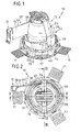
- Fig. 1 shows a perspective view in their entirety with 10 designated, inventive lamp.
- the lamp 10 is in formed substantially pot-shaped and has an annular Frame 23, on the radially projecting plate-shaped Attachment approaches 11 are attached, with which the lamp 10th e.g. in a designated installation space in a ceiling wall a room can be fixed.
- the frame 23 also has axially projecting plate-shaped Fortsuits 40 on which a bracket 24 a Receiving device 13 for a light source 35 shown in FIG. 4 is appropriate.
- the bracket 24 is with the plate-shaped projections 40th connected via joints 14, whereby the receiving device 13 to an indicated in Fig. 6 axis 42 is pivotable around.
- the Receiving device 13 can be locked in the desired position.
- the lamp 10 is connected via power supply lines a voltage source connected, wherein the Power supply lines for clarity not are shown.
- the receiving device 13 comprises a base 41, on the light source 35, e.g. a halogen lamp is arranged.
- the Receiving device 13 also has a first parabolic Reflector 33 and a second substantially funnel-shaped Reflector 34, which equalize the light of the light source 35.
- the light strikes a large part first on the reflector 34, the the light to the reflector 33 supplies.
- Coming from the reflector 33 occurs the light then passes through a lens 48 and is about another, the lamp 10 associated reflector 26, the one Cavity 32 surrounds a circular disk-shaped light exit surface 31 fed through the emitted by the lamp 35 Light leaves the light.
- the arrows 49 give the way of the light starting from the light source 35 again schematically.
- the reflector 26 is of an annular Stabilization element element 50 enclosed, whose respect Fig. 4 lower side forms an annular surface 37, the immediately adjacent to the light exit surface 31.
- the luminaire 10 has an example in FIG. 3 illustrated carrying device 12 for a plurality of schematically indicated Light emitting diodes 29 on.
- the carrying device 12 is, as later is discussed in more detail by the receiving device 13th spaced.
- the light-emitting diodes 29 provide within the meaning of this patent application the first light source.
- the of the receiving device 13th included light source 35 is referred to as the second light source.
- the support means 12 for the LEDs is connected via a Einstrahlabêt 15, which is substantially in the form of a has elongated oblique prism with rectangular base, connected to an annular portion 16.
- the Einstrahlabites 15 is inclined relative to the light exit surface 31 and has a Light entry surface 28 for the light of the LEDs 29.
- the LED light is through the Einstrahlabites 15 a example in FIG. 4 illustrated light entry surface 47, the Einstrahlabrough 15 with the annular portion 16 connects, supplied and passes through this surface into the annular portion 16 a.
- the irradiation section 15 stands tangentially from the annular portion 16 and thereby causes an irradiation of the LED light in the circumferential direction 17 of the annular portion 16.
- the sections 15 and 16 form together a light guide section 27, the light of the Light emitting diodes 29 in one by the geometric shape of the Licht Installationsabiteses 27 defined light guide direction along a light guide path, which in plan view substantially the shape a "p" has passed on.
- the light guide section 27 may for example, be formed in one or two pieces.
- the light guide section 27 is as Solid body made of a translucent material like e.g. made of glass or of a translucent plastic, in particular PMMA. In this case, there is a redirect of the LED light via total reflection at the interfaces possible.
- An embodiment of the light guide section 27 as a hollow body is alternatively conceivable. The light transmission is then e.g. at mirrored inner surfaces of the section 27.
- the bottom of the annular Section 16 formed as an annular light-emitting surface 30, which lies in the plane 43 defined by the light exit surface 31.
- the light exit surface 30 encloses the light exit surface 31, wherein between the light exit surfaces 30 and 31, the element 50 with its e.g. opaque surface 37 is located.
- the light exit surface 30, through which the LED light emerges, represents for the purposes of this patent application, the first light exit surface group; the second light source 35 associated light exit surface 31st represents the second light exit surface.
- the support 12 is located on the side of the plane 43, on which the receiving device 13 is located and is as shown in FIG. 5 spaced from the plane 43 by a length s. moreover has the support 12 along the plane 43 of the first Light exit surface 30 a distance t.
- the spacing the carrying device 12 with respect to the first light exit surface 30th both perpendicular to the plane 43 (distance s), as well as along the Level 43 (distance t) can be a thermal influence of LEDs 29 through the second light source 35 largely be avoided.
- this arrangement of the Carrying device 12 a simplified construction of the lamp 10th possible.
- the support device 12 may in an outer region of Luminaire 10 are arranged, in which there are no other components the light are, so that the support means 12 easily is accessible and an assembly is easy to carry out.
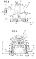
- the annular portion 16 in the area surrounded by the frame 23 has a substantially funnel-shaped axial section 38.
- this section 38 has a step 39 near the plane 43.
- An alternative embodiment of the funnel-shaped section 38 is shown in FIG.
- the wall thickness increases there with decreasing distance to the level 43 continuously; there is no level provided.
- the sections 38 in addition to the curvature in the circumferential direction 17 about the axis of curvature M has a curvature in at least one other direction.
- the axial section 38 curves around a curvature axis, which is designated in FIG. 6 by K 1 and K 2 and forms a circular path which rotates around the axial section 38.
- the light entry surface 28, the light guide section 27 and the light exit surface 30 together form a Light emission element 21.
- the light guide section 27 and the Light emitting element 21 thus differ in that the Light emitting element 21 in contrast to the light guide section 27 also the light entry surface 28 and the light exit surface 30th includes.
- the light of the LEDs 29 and the light of the second Light source 35 can be both in color, as well as in intensity differ. Both light sources 29, 35 can light simultaneously but not necessarily.
- the Light sources 29, 35 canchronizations- and Be associated with control devices that an independent driving the two light sources 29, 35 allow each other.
- the control device for the light-emitting diodes 29, for example, in the Carrying device 12 may be housed.
- the control device for the second light source 35 may, for example, in its associated Recording device 13 may be arranged.
- the lamp 10 is so controllable that e.g. only the light emitting diodes 29 emit light and thereby, e.g. one Provide emergency light.
- Emitting both light sources 29, 35 simultaneously Light the light-emitting diode, for example, takes over the function an accent light.
- the LED light can for Contrast reduction in the region of the second light exit surface 31 serve.
- both light sources 29, 35 can be dimmed be educated.
- a possible light path 46 is shown in FIG. 2 shown as a sweep train in the manner of a zig-zag line schematically. For clarity, only the beginning of the light path 46 shown in the vicinity of the Einstrahlabiteses 15. The majority of the LED light passes through the annular portion 16 several times Circumferential direction 17 before it hits the first light exit surface 30 and exits the lamp 10. These reflections are made mainly on the curved inner surfaces 20 of the Light emission element 21. At each reflection the LED light cones become expanded and mixed so.
- a prismatic structure 18 is provided.
- Prismatic structures 19 are also at the upper boundary surface 22 of the annular Section 16 attached. Through the structures 18 and 19 is a Scattering of the incident LED light causes.
- the annular portion 16 is through a tubular cover member 45 from the interior 36 of the lamp 10th separated. This will cause the light to penetrate the second Light source 35 in the light emitting element 21 largely prevented.
- Another cover member 25 may be above with respect to FIG. 4 the upper boundary surface 22 of the annular portion 16th are located.
- Fig. 4 shows the relationship between the different heights l 1 , l 2 of the annular portion 16 and its wall thickness d.
- the heights l 1 and l 2 are larger, in particular significantly larger than the wall thickness d.
- the height of the annular portion 16 decreases in the circumferential direction 17, starting from the surface 47, at which the Einstrahlabites 15 merges into the annular portion 16 (height l 1 ) from. At approximately 180 ° from the surface 47 in the circumferential direction 17, the annular portion 16 has the smaller height l 2 .
- a luminaire according to the Embodiment already with very few LEDs, e.g. one red, a green and a blue light emitting diode, a very homogeneous light emission of the LED light allows.
Landscapes
- Engineering & Computer Science (AREA)
- General Engineering & Computer Science (AREA)
- Physics & Mathematics (AREA)
- General Physics & Mathematics (AREA)
- Optics & Photonics (AREA)
- Non-Portable Lighting Devices Or Systems Thereof (AREA)
Abstract
Description
und
Claims (17)
- Leuchte (10) zur Anbringung an einer Gebäudefläche oder einer Gebäudeteilfläche, wie z.B. an einer Decke, einer Wand oder einem Boden eines Raumes, umfassend eine Trageinrichtung (12) für mehrere Leuchtdioden (29) und ein Lichtemissionselement (21), welches eine der Trageinrichtung (12) benachbarte Lichteintrittsfläche (28) für das von den Leuchtdioden (29) ausgesandte Licht, eine Lichtaustrittsfläche (30) und einen Lichtführungsabschnitt (27) umfasst, der die Lichteintrittsfläche (28) und die Lichtaustrittsfläche (30) miteinander verbindet, dadurch gekennzeichnet, dass der Lichtführungsabschnitt (27) gekrümmte Innenflächen (20) aufweist, und dass eine Weiterleitung des Lichtes von der Lichteintrittsfläche (28) zu der Lichtaustrittsfläche (30) durch den Lichtführungsabschnitt (27) hindurch im wesentlichen über mehrfache Reflexionen an den Innenflächen (20) erfolgt.
- Leuchte nach Anspruch 1, dadurch gekennzeichnet, dass die Lichteintrittsfläche (28) derart von der Lichtaustrittsfläche (30) beabstandet und relativ zu dieser angeordnet ist, dass höchstens ein geringer Teil der Lichtaustrittsfläche (30) innerhalb des Lichtführungsabschnittes (27) auf die Lichteintrittsfläche (28) projizierbar ist.
- Leuchte zur Anbringung an einer Gebäudefläche oder einer Gebäudeteilfläche, wie z.B. an einer Decke, einer Wand oder einem Boden eines Raumes, umfassend eine Trageinrichtung (12) für mehrere Leuchtdioden (29), ein Lichtemissionselement (21), welches eine der Trageinrichtung (12) benachbarte Lichteintrittsfläche (28) für das von den Leuchtdioden (29) ausgesandte Licht, eine erste Lichtaustrittsfläche (30) und einen Lichtführungsabschnitt (27) aufweist, der die Lichteintrittsfläche (28) und die erste Lichtaustrittsfläche (30) miteinander verbindet, sowie eine Aufnahmeeinrichtung (13) für eine zweite Lichtquelle (35), und eine dieser Aufnahmeeinrichtung (13) zugeordnete zweite Lichtaustrittsfläche (31), dadurch gekennzeichnet, dass die Lichteintrittsfläche (28) derart von der ersten Lichtaustrittsfläche (30) beabstandet und relativ zu dieser angeordnet ist, dass höchstens ein geringer Teil der ersten Lichtaustrittsfläche (30) innerhalb des Lichtführungsabschnittes (27) auf die Lichteintrittsfläche (28) projizierbar ist.
- Leuchte nach Anspruch 3, dadurch gekennzeichnet, dass der Lichtführungsabschnitt (27) gekrümmte Innenflächen (20) aufweist, und dass eine Weiterleitung des Lichtes von der Lichteintrittsfläche (28) zu der ersten Lichtaustrittsfläche (30) durch den Lichtführungsabschnitt (27) hindurch im wesentlichen über mehrfache Reflexionen an den Innenflächen (20) erfolgt.
- Leuchte (10) zur Anbringung an einer Gebäudefläche oder einer Gebäudeteilfläche, wie z.B. an einer Decke, einer Wand oder einem Boden eines Raumes, insbesondere nach einem der vorhergehenden Ansprüche, umfassend eine Trageinrichtung (12) für mehrere Leuchtdioden (29), ein Lichtemissionselement (21), welches eine der Trageinrichtung (12) benachbarte Lichteintrittsfläche (28) für das von den Leuchtdioden (29) ausgesandte Licht, eine erste im wesentlichen kreisringförmig ausgebildete Lichtaustrittsfläche (30) und einen Lichtführungsabschnitt (27) aufweist, der die Lichteintrittsfläche (28) und die erste Lichtaustrittsfläche (30) miteinander verbindet, eine Aufnahmeeinrichtung (13) für eine zweite Lichtquelle (35), und eine dieser Aufnahmeeinrichtung (13) zugeordnete zweite Lichtaustrittsfläche (31), die von der ersten Lichtaustrittsfläche (30) umschlossen wird, dadurch gekennzeichnet, dass das Lichtemissionselement einen im wesentlichen ringförmigen Abschnitt (16) und einen Einstrahlabschnitt (15) umfasst, wobei der Einstrahlabschnitt (15) die Trageinrichtung (12) der Leuchtdioden (29) mit dem ringförmigen Abschnitt (16) verbindet, und wobei die Höhe (l1,l2) des ringförmigen Abschnitts größer ist als seine Wandstärke (d).
- Leuchte nach Anspruch 5, dadurch gekennzeichnet, daß das Licht der Leuchtdioden (29) im wesentlichen in Umfangsrichtung (17) des ringförmigen Abschnitts (16) in diesen einstrahlt und daß eine Weiterleitung des Lichtes innerhalb des ringförmigen Abschnittes (16) im wesentlichen in Umfangsrichtung (17) erfolgt.
- Leuchte nach Anspruch 5 oder 6, dadurch gekennzeichnet, dass sich der ringförmige Abschnitt (16) im Querschnitt zu der ersten Lichtaustrittsfläche (31) hin trichterförmig erweitert.
- Leuchte nach einem der Ansprüche 5 bis 7, dadurch gekennzeichnet, dass die Wandstärke (d) des ringförmigen Abschnittes (16) zu der ersten Lichtaustrittsfläche (31) hin zunimmt.
- Leuchte nach einem der Ansprüche 5 bis 8, dadurch gekennzeichnet, dass der ringförmige Abschnitt (16) eine erste Krümmungsachse (M) und eine zweite Krümmungsachse (K1, K2) aufweist, die im wesentlichen senkrecht aufeinander stehen.
- Leuchte nach einem der vorhergehenden Ansprüche, dadurch gekennzeichnet, dass das Lichtemissionselement (21) einen ringförmigen Abschnitt (16) und einen tangential von diesem Abschnitt (16) abstehenden Einstrahlabschnitt (15) umfasst.
- Leuchte nach einem der vorhergehenden Ansprüche, dadurch gekennzeichnet, dass die Lichtaustrittsfläche (30) des Lichtemissionselementes (21) im wesentlichen in einer Ebene (43) liegt, dass die Trageinrichtung (12) von dieser Ebene (43) beabstandet ist, und dass die Trageinrichtung (12) entlang der Ebene (43) von der Lichtaustrittsfläche (30) beabstandet angeordnet ist.
- Leuchte nach einem der vorhergehenden Ansprüche, dadurch gekennzeichnet, dass das Lichtemissionselement (21) einen ringförmigen Abschnitt (16) umfasst, welcher sich ausgehend von einer Stelle (47), an der das LED-Licht in den ringförmigen Abschnitt eindringt, in Umfangsrichtung (17) verjüngt.
- Leuchte nach einem der vorhergehenden Ansprüche, dadurch gekennzeichnet, dass das Lichtemissionselement (21) im wesentlichen massiv ausgebildet ist und aus einem lichtdurchlässigen Material, wie z.B. Glas oder Kunststoff, insbesondere aus PMMA, besteht.
- Leuchte nach einem der vorhergehenden Ansprüche, dadurch gekennzeichnet, dass das Lichtemissionselement (21) Innenflächen (20, 22, 44) umfasst, die wenigstens teilweise verspiegelt sind.
- Leuchte nach einem der vorhergehenden Ansprüche, dadurch gekennzeichnet, dass innerhalb des Lichtemissionselementes (21 ) Totalreflexion stattfindet.
- Leuchte nach einem der vorhergehenden Ansprüche, dadurch gekennzeichnet, dass die Leuchtdioden (29) zu einer Baueinheit zusammengefasst sind.
- Leuchte nach einem der vorhergehenden Ansprüche, dadurch gekennzeichnet, dass der Lichtführungsabschnitt (27) Grenzflächen (22, 44) umfasst, die eine mikrostrukturierte, insbesondere eine prismatisch strukturierte Form (18, 19) aufweisen.
Applications Claiming Priority (2)
| Application Number | Priority Date | Filing Date | Title |
|---|---|---|---|
| DE10341219A DE10341219A1 (de) | 2003-09-04 | 2003-09-04 | Leuchte zur Anbringung an einer Gebäudefläche oder Gebäudeteilfläche |
| DE10341219 | 2003-09-04 |
Publications (2)
| Publication Number | Publication Date |
|---|---|
| EP1512902A2 true EP1512902A2 (de) | 2005-03-09 |
| EP1512902A3 EP1512902A3 (de) | 2007-11-21 |
Family
ID=34129682
Family Applications (1)
| Application Number | Title | Priority Date | Filing Date |
|---|---|---|---|
| EP04020760A Withdrawn EP1512902A3 (de) | 2003-09-04 | 2004-09-01 | Leuchte zur Anbringung an einer Gebäudefläche oder Gebäudeteilfläche |
Country Status (4)
| Country | Link |
|---|---|
| US (1) | US20050117332A1 (de) |
| EP (1) | EP1512902A3 (de) |
| JP (1) | JP2005085771A (de) |
| DE (1) | DE10341219A1 (de) |
Cited By (5)
| Publication number | Priority date | Publication date | Assignee | Title |
|---|---|---|---|---|
| WO2008137905A1 (en) * | 2007-05-07 | 2008-11-13 | Cree Led Lighting Solutions, Inc. | Light fixtures and lighting devices |
| US7625103B2 (en) | 2006-04-21 | 2009-12-01 | Cree, Inc. | Multiple thermal path packaging for solid state light emitting apparatus and associated assembling methods |
| US7648257B2 (en) | 2006-04-21 | 2010-01-19 | Cree, Inc. | Light emitting diode packages |
| US8258682B2 (en) | 2007-02-12 | 2012-09-04 | Cree, Inc. | High thermal conductivity packaging for solid state light emitting apparatus and associated assembling methods |
| WO2016086252A1 (de) * | 2014-12-05 | 2016-06-09 | Tridonic Gmbh & Co Kg | Beleuchtungssystem zum wechseln der abstrahlcharakteristik |
Families Citing this family (5)
| Publication number | Priority date | Publication date | Assignee | Title |
|---|---|---|---|---|
| US8596825B2 (en) * | 2009-08-04 | 2013-12-03 | 3M Innovative Properties Company | Solid state light with optical guide and integrated thermal guide |
| DE102009058939A1 (de) | 2009-12-17 | 2011-06-22 | ERCO GmbH, 58507 | Leuchte |
| US8487518B2 (en) | 2010-12-06 | 2013-07-16 | 3M Innovative Properties Company | Solid state light with optical guide and integrated thermal guide |
| USD642704S1 (en) | 2010-12-06 | 2011-08-02 | 3M Innovative Properties Company | Solid state light assembly |
| US9587805B2 (en) * | 2013-09-20 | 2017-03-07 | Osram Sylvania Inc. | Solid-state luminaire with electronically adjustable light beam distribution |
Family Cites Families (20)
| Publication number | Priority date | Publication date | Assignee | Title |
|---|---|---|---|---|
| JPS4515930Y1 (de) * | 1967-11-28 | 1970-07-03 | ||
| US4498125A (en) * | 1982-09-29 | 1985-02-05 | Adjustable Fixture Company | Lamp with one arm fork support |
| US4949226A (en) * | 1988-06-24 | 1990-08-14 | Koito Seisakusko Co., Ltd. | Projector-type lighting device of expanded outline appearance for use as a vehicular headlamp or the like |
| DE29620583U1 (de) * | 1996-11-27 | 1997-02-13 | Kundisch Microtech GmbH & Co. KG, 78056 Villingen-Schwenningen | Beleuchtungskörper mit stufenlos einstellbarer Farbänderung des Lichtes und des Lichtkegels |
| US6322228B1 (en) * | 1998-12-30 | 2001-11-27 | Harold Feldman | Lamp with electroluminescent connectors to power source |
| JP2000207916A (ja) * | 1999-01-11 | 2000-07-28 | Yamaha Corp | 照明装置および操作装置 |
| DE29923835U1 (de) * | 1999-04-07 | 2001-04-05 | Zumtobel Staff Gmbh | Beleuchtungsanordnung zur Anbringung an der Decke oder einer Wand eines Raumes |
| US6244730B1 (en) * | 1999-05-07 | 2001-06-12 | Phoenix Products Company, Inc. | Light source with easily accessed light guide |
| DE19954794A1 (de) * | 1999-11-13 | 2001-05-17 | Bosch Gmbh Robert | Beleuchtungseinheit |
| US6422718B1 (en) * | 1999-11-18 | 2002-07-23 | Integrated Systems Technologies Limited | Non-imaging light source for uniform illumination applications |
| DE20007134U1 (de) * | 2000-04-18 | 2000-08-17 | OSRAM Opto Semiconductors GmbH & Co. oHG, 93049 Regensburg | Leuchte mit einstellbarem Farbort |
| US7202613B2 (en) * | 2001-05-30 | 2007-04-10 | Color Kinetics Incorporated | Controlled lighting methods and apparatus |
| US6960892B2 (en) * | 2000-12-01 | 2005-11-01 | Loughrey James F | Variable output single constant source light fixture |
| US6471368B1 (en) * | 2001-09-26 | 2002-10-29 | Yu-Chu Lin | Secondary alert light for motor vehicles |
| WO2003059012A1 (de) * | 2002-01-07 | 2003-07-17 | Patent - Treuhand - Gesellschaft für Elektrische Glühlampen mbH | Lampe |
| US6789929B1 (en) * | 2002-09-11 | 2004-09-14 | Dj Auto Components Corp. | Lamp structure |
| US6758576B2 (en) * | 2002-11-04 | 2004-07-06 | Frank Tsao | Portable stack lamp |
| US6619829B1 (en) * | 2002-11-05 | 2003-09-16 | Shih Ling Chen | Lighting device for vehicle |
| US6821010B2 (en) * | 2002-11-15 | 2004-11-23 | The Holmes Group, Inc. | Decorative lamp with illuminated color changeable column |
| US6863414B2 (en) * | 2002-12-27 | 2005-03-08 | Quanta Display Incorporation | Front light module |
-
2003
- 2003-09-04 DE DE10341219A patent/DE10341219A1/de not_active Ceased
-
2004
- 2004-09-01 US US10/931,787 patent/US20050117332A1/en not_active Abandoned
- 2004-09-01 EP EP04020760A patent/EP1512902A3/de not_active Withdrawn
- 2004-09-03 JP JP2004290731A patent/JP2005085771A/ja active Pending
Cited By (8)
| Publication number | Priority date | Publication date | Assignee | Title |
|---|---|---|---|---|
| US7625103B2 (en) | 2006-04-21 | 2009-12-01 | Cree, Inc. | Multiple thermal path packaging for solid state light emitting apparatus and associated assembling methods |
| US7648257B2 (en) | 2006-04-21 | 2010-01-19 | Cree, Inc. | Light emitting diode packages |
| US8258682B2 (en) | 2007-02-12 | 2012-09-04 | Cree, Inc. | High thermal conductivity packaging for solid state light emitting apparatus and associated assembling methods |
| WO2008137905A1 (en) * | 2007-05-07 | 2008-11-13 | Cree Led Lighting Solutions, Inc. | Light fixtures and lighting devices |
| US8136965B2 (en) | 2007-05-07 | 2012-03-20 | Cree, Inc. | Light fixtures and lighting devices |
| US8789975B2 (en) | 2007-05-07 | 2014-07-29 | Cree, Inc. | Light fixtures and lighting devices |
| WO2016086252A1 (de) * | 2014-12-05 | 2016-06-09 | Tridonic Gmbh & Co Kg | Beleuchtungssystem zum wechseln der abstrahlcharakteristik |
| US10728974B2 (en) | 2014-12-05 | 2020-07-28 | Tridonic Gmbh & Co Kg | Lighting system for changing the emission characteristics operating in at least a first mode and a second mode and comprising LEDS, a converter, and an operating unit |
Also Published As
| Publication number | Publication date |
|---|---|
| EP1512902A3 (de) | 2007-11-21 |
| DE10341219A1 (de) | 2005-03-31 |
| JP2005085771A (ja) | 2005-03-31 |
| US20050117332A1 (en) | 2005-06-02 |
Similar Documents
| Publication | Publication Date | Title |
|---|---|---|
| EP0762515B1 (de) | Optikkörper für mindestens eine LED | |
| EP2893249B1 (de) | Leuchteinheit für einen scheinwerfer | |
| AT516259B1 (de) | Lichtsystem für ein Kraftfahrzeug | |
| DE102008021290B4 (de) | Lichtleiterstruktur für eine Kraftfahrzeugbeleuchtungseinrichtung und Kraftfahrzeugbeleuchtungseinrichtung mit einer solchen Lichtleiterstruktur | |
| DE102010041478A1 (de) | Anordnung zur gerichteten Lichtabgabe | |
| EP1031464A2 (de) | Einrichtung zur Beleuchtung von Räumen, Körpern oder Flächen | |
| DE102011012130A1 (de) | Beleuchtungsvorrichtung | |
| DE102010008359A1 (de) | Beleuchtungsanordnung | |
| EP1398562A1 (de) | Leuchte zur Erzielung eines scharfkantig ausgebildeten Lichtkegels | |
| EP3655289B1 (de) | Bauteil für ein fahrzeug | |
| EP1512902A2 (de) | Leuchte zur Anbringung an einer Gebäudefläche oder Gebäudeteilfläche | |
| EP3449299A1 (de) | Leuchtenoptik | |
| EP3171077B1 (de) | Blendarme lichttechnik | |
| EP2796769B1 (de) | LED-Leuchte mit einer Lichtleiter-Anordnung | |
| DE102015103004A1 (de) | Faseroptischer Lichtleiter, Befestigungselement für denselben und Beleuchtungsvorrichtung | |
| DE102011051541A1 (de) | Beleuchtungsvorrichtung für Fahrzeuge | |
| DE202015104882U1 (de) | Beleuchtungsanordnung | |
| EP2333402B1 (de) | Leuchte mit Hohllichtleiter | |
| DE202007003497U1 (de) | Lichtleitelement | |
| AT16189U1 (de) | LED-Leuchte mit einem Basiselement und einem stabförmigen Element | |
| DE20313905U1 (de) | Leuchte zur Anbringung an einer Gebäudefläche oder einer Gebäudeteilfläche | |
| EP3543600A2 (de) | Mischstab zum mischen eines lichtstrahlbündels sowie beleuchtungsvorrichtung mit einem solchen mischstab | |
| DE202008012463U1 (de) | Anordnung zur Bildung einer länglichen Lichtquelle | |
| WO2007147481A1 (de) | Sanitärarmatur mit wenigstens einer beleuchtungseinrichtung | |
| DE102018133108A1 (de) | Laserlichtleuchte mit Remote-Phosphor |
Legal Events
| Date | Code | Title | Description |
|---|---|---|---|
| PUAI | Public reference made under article 153(3) epc to a published international application that has entered the european phase |
Free format text: ORIGINAL CODE: 0009012 |
|
| AK | Designated contracting states |
Kind code of ref document: A2 Designated state(s): AT BE BG CH CY CZ DE DK EE ES FI FR GB GR HU IE IT LI LU MC NL PL PT RO SE SI SK TR |
|
| AX | Request for extension of the european patent |
Extension state: AL HR LT LV MK |
|
| PUAL | Search report despatched |
Free format text: ORIGINAL CODE: 0009013 |
|
| AK | Designated contracting states |
Kind code of ref document: A3 Designated state(s): AT BE BG CH CY CZ DE DK EE ES FI FR GB GR HU IE IT LI LU MC NL PL PT RO SE SI SK TR |
|
| AX | Request for extension of the european patent |
Extension state: AL HR LT LV MK |
|
| RIC1 | Information provided on ipc code assigned before grant |
Ipc: G02B 6/00 20060101ALI20071012BHEP Ipc: F21V 7/00 20060101ALI20071012BHEP Ipc: F21S 8/02 20060101AFI20041125BHEP |
|
| 17P | Request for examination filed |
Effective date: 20080514 |
|
| 17Q | First examination report despatched |
Effective date: 20080618 |
|
| AKX | Designation fees paid |
Designated state(s): AT BE BG CH CY CZ DE DK EE ES FI FR GB GR HU IE IT LI LU MC NL PL PT RO SE SI SK TR |
|
| RAP1 | Party data changed (applicant data changed or rights of an application transferred) |
Owner name: ERCO GMBH |
|
| STAA | Information on the status of an ep patent application or granted ep patent |
Free format text: STATUS: THE APPLICATION IS DEEMED TO BE WITHDRAWN |
|
| 18D | Application deemed to be withdrawn |
Effective date: 20110401 |