EP3248841A1 - Auf einem fahrzeug montierte steuerungsvorrichtung und verfahren zur steuerung des fahrzeugs - Google Patents
Auf einem fahrzeug montierte steuerungsvorrichtung und verfahren zur steuerung des fahrzeugs Download PDFInfo
- Publication number
- EP3248841A1 EP3248841A1 EP17169539.8A EP17169539A EP3248841A1 EP 3248841 A1 EP3248841 A1 EP 3248841A1 EP 17169539 A EP17169539 A EP 17169539A EP 3248841 A1 EP3248841 A1 EP 3248841A1
- Authority
- EP
- European Patent Office
- Prior art keywords
- vehicle
- sensed
- output
- lamps
- visible light
- Prior art date
- Legal status (The legal status is an assumption and is not a legal conclusion. Google has not performed a legal analysis and makes no representation as to the accuracy of the status listed.)
- Withdrawn
Links
- 238000000034 method Methods 0.000 title abstract description 45
- 230000033001 locomotion Effects 0.000 claims abstract description 17
- 230000004044 response Effects 0.000 claims abstract description 14
- 238000004891 communication Methods 0.000 description 47
- 230000001276 controlling effect Effects 0.000 description 44
- 230000006870 function Effects 0.000 description 18
- 239000000725 suspension Substances 0.000 description 10
- 238000001514 detection method Methods 0.000 description 9
- 238000005516 engineering process Methods 0.000 description 9
- 230000001133 acceleration Effects 0.000 description 7
- 230000003287 optical effect Effects 0.000 description 5
- 238000010586 diagram Methods 0.000 description 4
- 239000000446 fuel Substances 0.000 description 4
- 238000012545 processing Methods 0.000 description 4
- 238000003491 array Methods 0.000 description 3
- 230000008859 change Effects 0.000 description 3
- 230000008569 process Effects 0.000 description 3
- 230000005236 sound signal Effects 0.000 description 3
- XUIMIQQOPSSXEZ-UHFFFAOYSA-N Silicon Chemical compound [Si] XUIMIQQOPSSXEZ-UHFFFAOYSA-N 0.000 description 2
- 230000005540 biological transmission Effects 0.000 description 2
- 238000011161 development Methods 0.000 description 2
- 239000000428 dust Substances 0.000 description 2
- 230000001815 facial effect Effects 0.000 description 2
- 239000004973 liquid crystal related substance Substances 0.000 description 2
- 238000012986 modification Methods 0.000 description 2
- 230000004048 modification Effects 0.000 description 2
- 238000012544 monitoring process Methods 0.000 description 2
- 230000002265 prevention Effects 0.000 description 2
- 229910052710 silicon Inorganic materials 0.000 description 2
- 239000010703 silicon Substances 0.000 description 2
- 239000007787 solid Substances 0.000 description 2
- 238000012706 support-vector machine Methods 0.000 description 2
- 230000003044 adaptive effect Effects 0.000 description 1
- 230000004075 alteration Effects 0.000 description 1
- 238000013528 artificial neural network Methods 0.000 description 1
- 238000002485 combustion reaction Methods 0.000 description 1
- 238000013500 data storage Methods 0.000 description 1
- 230000007423 decrease Effects 0.000 description 1
- 230000000694 effects Effects 0.000 description 1
- 239000002803 fossil fuel Substances 0.000 description 1
- 238000005286 illumination Methods 0.000 description 1
- 238000009434 installation Methods 0.000 description 1
- 230000007774 longterm Effects 0.000 description 1
- 239000011159 matrix material Substances 0.000 description 1
- 239000003595 mist Substances 0.000 description 1
- 239000003921 oil Substances 0.000 description 1
- 230000008520 organization Effects 0.000 description 1
- 230000001105 regulatory effect Effects 0.000 description 1
- 230000009131 signaling function Effects 0.000 description 1
- 230000003068 static effect Effects 0.000 description 1
- 239000010409 thin film Substances 0.000 description 1
- 238000012546 transfer Methods 0.000 description 1
- 238000002834 transmittance Methods 0.000 description 1
- 238000012795 verification Methods 0.000 description 1
- 230000000007 visual effect Effects 0.000 description 1
- XLYOFNOQVPJJNP-UHFFFAOYSA-N water Substances O XLYOFNOQVPJJNP-UHFFFAOYSA-N 0.000 description 1
Images


Classifications
-
- B—PERFORMING OPERATIONS; TRANSPORTING
- B60—VEHICLES IN GENERAL
- B60Q—ARRANGEMENT OF SIGNALLING OR LIGHTING DEVICES, THE MOUNTING OR SUPPORTING THEREOF OR CIRCUITS THEREFOR, FOR VEHICLES IN GENERAL
- B60Q1/00—Arrangement of optical signalling or lighting devices, the mounting or supporting thereof or circuits therefor
- B60Q1/26—Arrangement of optical signalling or lighting devices, the mounting or supporting thereof or circuits therefor the devices being primarily intended to indicate the vehicle, or parts thereof, or to give signals, to other traffic
- B60Q1/50—Arrangement of optical signalling or lighting devices, the mounting or supporting thereof or circuits therefor the devices being primarily intended to indicate the vehicle, or parts thereof, or to give signals, to other traffic for indicating other intentions or conditions, e.g. request for waiting or overtaking
- B60Q1/525—Arrangement of optical signalling or lighting devices, the mounting or supporting thereof or circuits therefor the devices being primarily intended to indicate the vehicle, or parts thereof, or to give signals, to other traffic for indicating other intentions or conditions, e.g. request for waiting or overtaking automatically indicating risk of collision between vehicles in traffic or with pedestrians, e.g. after risk assessment using the vehicle sensor data
-
- B—PERFORMING OPERATIONS; TRANSPORTING
- B60—VEHICLES IN GENERAL
- B60Q—ARRANGEMENT OF SIGNALLING OR LIGHTING DEVICES, THE MOUNTING OR SUPPORTING THEREOF OR CIRCUITS THEREFOR, FOR VEHICLES IN GENERAL
- B60Q1/00—Arrangement of optical signalling or lighting devices, the mounting or supporting thereof or circuits therefor
- B60Q1/26—Arrangement of optical signalling or lighting devices, the mounting or supporting thereof or circuits therefor the devices being primarily intended to indicate the vehicle, or parts thereof, or to give signals, to other traffic
- B60Q1/44—Arrangement of optical signalling or lighting devices, the mounting or supporting thereof or circuits therefor the devices being primarily intended to indicate the vehicle, or parts thereof, or to give signals, to other traffic for indicating braking action or preparation for braking, e.g. by detection of the foot approaching the brake pedal
- B60Q1/444—Arrangement of optical signalling or lighting devices, the mounting or supporting thereof or circuits therefor the devices being primarily intended to indicate the vehicle, or parts thereof, or to give signals, to other traffic for indicating braking action or preparation for braking, e.g. by detection of the foot approaching the brake pedal with indication of the braking strength or speed changes, e.g. by changing shape or intensity of the indication
-
- B—PERFORMING OPERATIONS; TRANSPORTING
- B60—VEHICLES IN GENERAL
- B60Q—ARRANGEMENT OF SIGNALLING OR LIGHTING DEVICES, THE MOUNTING OR SUPPORTING THEREOF OR CIRCUITS THEREFOR, FOR VEHICLES IN GENERAL
- B60Q1/00—Arrangement of optical signalling or lighting devices, the mounting or supporting thereof or circuits therefor
- B60Q1/26—Arrangement of optical signalling or lighting devices, the mounting or supporting thereof or circuits therefor the devices being primarily intended to indicate the vehicle, or parts thereof, or to give signals, to other traffic
- B60Q1/50—Arrangement of optical signalling or lighting devices, the mounting or supporting thereof or circuits therefor the devices being primarily intended to indicate the vehicle, or parts thereof, or to give signals, to other traffic for indicating other intentions or conditions, e.g. request for waiting or overtaking
- B60Q1/525—Arrangement of optical signalling or lighting devices, the mounting or supporting thereof or circuits therefor the devices being primarily intended to indicate the vehicle, or parts thereof, or to give signals, to other traffic for indicating other intentions or conditions, e.g. request for waiting or overtaking automatically indicating risk of collision between vehicles in traffic or with pedestrians, e.g. after risk assessment using the vehicle sensor data
- B60Q1/535—Arrangement of optical signalling or lighting devices, the mounting or supporting thereof or circuits therefor the devices being primarily intended to indicate the vehicle, or parts thereof, or to give signals, to other traffic for indicating other intentions or conditions, e.g. request for waiting or overtaking automatically indicating risk of collision between vehicles in traffic or with pedestrians, e.g. after risk assessment using the vehicle sensor data to prevent rear-end collisions, e.g. by indicating safety distance at the rear of the vehicle
-
- B—PERFORMING OPERATIONS; TRANSPORTING
- B60—VEHICLES IN GENERAL
- B60T—VEHICLE BRAKE CONTROL SYSTEMS OR PARTS THEREOF; BRAKE CONTROL SYSTEMS OR PARTS THEREOF, IN GENERAL; ARRANGEMENT OF BRAKING ELEMENTS ON VEHICLES IN GENERAL; PORTABLE DEVICES FOR PREVENTING UNWANTED MOVEMENT OF VEHICLES; VEHICLE MODIFICATIONS TO FACILITATE COOLING OF BRAKES
- B60T7/00—Brake-action initiating means
- B60T7/12—Brake-action initiating means for automatic initiation; for initiation not subject to will of driver or passenger
- B60T7/22—Brake-action initiating means for automatic initiation; for initiation not subject to will of driver or passenger initiated by contact of vehicle, e.g. bumper, with an external object, e.g. another vehicle, or by means of contactless obstacle detectors mounted on the vehicle
-
- B—PERFORMING OPERATIONS; TRANSPORTING
- B60—VEHICLES IN GENERAL
- B60W—CONJOINT CONTROL OF VEHICLE SUB-UNITS OF DIFFERENT TYPE OR DIFFERENT FUNCTION; CONTROL SYSTEMS SPECIALLY ADAPTED FOR HYBRID VEHICLES; ROAD VEHICLE DRIVE CONTROL SYSTEMS FOR PURPOSES NOT RELATED TO THE CONTROL OF A PARTICULAR SUB-UNIT
- B60W10/00—Conjoint control of vehicle sub-units of different type or different function
- B60W10/18—Conjoint control of vehicle sub-units of different type or different function including control of braking systems
-
- B—PERFORMING OPERATIONS; TRANSPORTING
- B60—VEHICLES IN GENERAL
- B60W—CONJOINT CONTROL OF VEHICLE SUB-UNITS OF DIFFERENT TYPE OR DIFFERENT FUNCTION; CONTROL SYSTEMS SPECIALLY ADAPTED FOR HYBRID VEHICLES; ROAD VEHICLE DRIVE CONTROL SYSTEMS FOR PURPOSES NOT RELATED TO THE CONTROL OF A PARTICULAR SUB-UNIT
- B60W30/00—Purposes of road vehicle drive control systems not related to the control of a particular sub-unit, e.g. of systems using conjoint control of vehicle sub-units
- B60W30/08—Active safety systems predicting or avoiding probable or impending collision or attempting to minimise its consequences
- B60W30/09—Taking automatic action to avoid collision, e.g. braking and steering
-
- G—PHYSICS
- G08—SIGNALLING
- G08G—TRAFFIC CONTROL SYSTEMS
- G08G1/00—Traffic control systems for road vehicles
- G08G1/16—Anti-collision systems
- G08G1/166—Anti-collision systems for active traffic, e.g. moving vehicles, pedestrians, bikes
Definitions
- This specification relates to a control device mounted on a vehicle and a method for controlling the vehicle.
- a vehicle is an apparatus capable of moving a user in the user-desired direction, and a representative example may be a car.
- a vehicle may be provided with various types of lamps.
- the vehicle includes various vehicle lamps having a lighting function of facilitating articles or objects near the vehicle to be recognized during driving at night, and a signaling function of notifying a driving state of the vehicle to other vehicles or pedestrians.
- a headlamp emitting light to a front side to ensure a driver's view may include devices operating in a manner of directly emitting light using lamps, such as a headlamp emitting light to a front side to ensure a driver's view, a brake lamp turned on when slamming the brake on, turn indicator lamps used upon a left turn or a right turn.
- lamps such as a headlamp emitting light to a front side to ensure a driver's view, a brake lamp turned on when slamming the brake on, turn indicator lamps used upon a left turn or a right turn.
- reflectors for reflecting light to facilitate the vehicle to be recognized from outside are mounted on front and rear sides of the vehicle.
- Installation criteria and standards of the vehicle lamps are regulated as rules to fully exhibit each function.
- ADAS advanced deriving assist system
- an aspect of the detailed description is to provide a control device mounted on a vehicle, capable of controlling lamps provided on the vehicle in an optimized manner, and a method for controlling the vehicle.
- Another aspect of the detailed description is to provide a control device mounted on a vehicle, capable of emitting light to a rear side of the vehicle even if a brake apparatus is not activated so as to prevent vehicles from being smashed into each other, and a method for controlling the vehicle.
- Another aspect of the detailed description is to provide a control device mounted on a vehicle, capable of emitting visible light to a rear side of the vehicle in an optimized manner while a brake apparatus is not activated, and a method for controlling the vehicle.
- a control device including a brake apparatus configured to brake a movement of a vehicle, rear lamps configured to output visible light to a rear of the vehicle in response to an operation of the brake apparatus, a sensing unit configured to sense at least one of information related to the vehicle and surrounding information related to the vehicle, and a processor configured to control the rear lamps to output the visible light to the rear of the vehicle, even without the operation of the brake apparatus, when the information sensed through the sensing unit corresponds to a preset condition.
- a vehicle in accordance with one embodiment of the present invention may include a control device described in this specification.
- a method for controlling a vehicle which includes a sensing unit, a brake apparatus, and rear lamps that emit visible light to the rear of the vehicle in response to an operation of the brake apparatus, in accordance with one embodiment of the present invention may include sensing at least one of information related to the vehicle and surrounding information related to the vehicle through the sensing unit, and controlling the rear lamps to output visible light to the rear of the vehicle, even without the operation of the brake apparatus, when the information sensed through the sensing unit meets a preset condition.
- the present invention can provide a new control method capable of preventing a rear-end collision by warning an accident to a rear vehicle in a manner of controlling rear lamps to emit light even though a brake apparatus is not operated.
- the present invention can provide rear lamps which can be controlled to output visible light in various manners such that a danger can be notified to a rear vehicle in an optimized (or intuitive) manner, and a control device capable of controlling the rear lamps.
- the present invention can provide rear lamps, which are capable of allowing a rear vehicle to more intuitively recognize a state of a vehicle disclosed herein or a relationship with the vehicle disclosed herein, by being controlled to output visible light in a different manner according to a type of a condition (preset condition) associated with the emission of the visible light, even without an operation of a brake apparatus, and a control device controlling the rear lamps.
- the present invention can warn a rear vehicle of a risk by turning on rear lamps even without an operation of a brake apparatus, when collision probability with the rear vehicle exceeds a reference value.
- the present invention can warn a driver of a rear vehicle in an optimized manner and thus remarkably enhance accident prevention by controlling rear lamps in various manners based on collision probability exceeding a reference value.
- the present invention can provide a control method of preventing a chain collision by controlling rear lamps to output light even without an operation of a brake apparatus, irrespective of collision probability with a first vehicle sensed at a rear of a vehicle disclosed herein, when collision probability with the a vehicle exceeds a reference value.
- the present invention can remarkably reduce an accident occurrence by warning a driver of a rear vehicle before a brake apparatus is operated, when brake lamps of a front vehicle sensed at a front of a vehicle disclosed herein are turned on under assumption that the rear vehicle sensed at a rear of the vehicle disclosed herein exists within a reference distance.
- the present invention can provide a control device capable of warning a risk to a driver of a rear vehicle in advance or at an optimized time point by controlling rear lamps to output light even without an operation of a brake apparatus at a generation time point of a forward collision warning (FCW), when collision probability with the rear vehicle exceeds a reference value although collision probability with a front vehicle is not as high as having to perform automatic emergency braking.
- FCW forward collision warning
- the present invention can provide a control method capable of controlling rear lamps to output visible light in an optimized manner, considering a surrounding environment, when the rear lamps emit light even without an operation of a brake apparatus.
- a singular representation may include a plural representation unless it represents a definitely different meaning from the context.
- a vehicle according to an embodiment of the present invention may be understood as a conception including cars, motorcycles and the like. Hereinafter, the vehicle will be described based on a car.
- the vehicle according to the embodiment of the present invention may be a conception including all of an internal combustion engine car having an engine as a power source, a hybrid vehicle having an engine and an electric motor as power sources, an electric vehicle having an electric motor as a power source, and the like.
- the vehicle according to the embodiment of the present invention may be an autonomous vehicle.
- a left side of a vehicle refers to a left side in a driving direction of the vehicle, and a right side of the vehicle refers to a right side in the driving direction.
- a front side is a forward driving direction
- a rear side is a backward driving direction
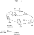
- FIG. 1 is a view illustrating appearance of a vehicle in accordance with an embodiment of the present invention.
- a vehicle 700 may include wheels 103FR, 103FL, 103RL, ..., which turn by a power source, and a steering apparatus for adjusting a driving (ongoing) direction of the vehicle 700.
- the steering apparatus may include a steering wheel.
- a user may decide a driving direction of the vehicle 700 using the steering wheel.
- a steering input received through the steering apparatus may be transferred to the steering wheel.
- the steering apparatus and the steering wheel may be connected to each other electrically or mechanically.
- the steering wheels may preferably be the front wheels 103FL and 103FR, but alternatively all of the front wheels 103FL and 103FR and the rear wheels 103RR may operate as the steering wheels.
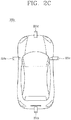
- FIGS. 2A to 2C are views illustrating various embodiments of a camera module included in a control device according to the present invention.
- a camera unit 200a may include an image sensor (e.g., CCD or CMOS), a lens 203, and a light shield 202 for shielding a part of light incident on the lens 203.
- an image sensor e.g., CCD or CMOS
- a lens 203 e.g., a lens 203
- a light shield 202 for shielding a part of light incident on the lens 203.
- the camera unit 200a may have a structure which is attachable on or detachable from an inner ceiling or a wind shield of the vehicle 700.
- the camera unit 200a may acquire surrounding images of the vehicle 700.
- the camera unit 200a may acquire front or rear images of the vehicle 700.
- the images acquired through the camera unit 200a may be transmitted to an image processor (not illustrated).
- the image acquired through the camera unit 200a may be referred to as a mono image.
- the camera unit 200a described with reference to FIG. 2A may be referred to as a mono camera unit or a single camera unit.
- a camera unit 200b may include a first camera 211a and a second camera 211b.
- the first camera 211a may include a first image sensor (e.g., CCD or CMOS) and a first lens 213a.
- the second camera 211b may include a second image sensor (e.g., CCD or CMOS) and a second lens 213b.
- the camera unit 200b may include a first light shield 212a and a second light shield 212b for partially shielding light incident on the first lens 213a and the second lens 213b.
- the camera unit 200b may have a structure which is attachable on or detachable from an inner ceiling or a wind shield of the vehicle 700.
- the camera unit 200b may acquire surrounding images of the vehicle 700.
- the camera unit 200b may acquire front or rear images of the vehicle 700.
- the images acquired through the camera unit 200b may be transmitted to an image processor (not illustrated).
- the images acquired through the first camera 211a and the second camera 211b may be referred to as stereo images.
- the camera unit 200b described with reference to FIG. 2B may be referred to as a stereo camera unit.
- a camera unit 200c may include a plurality of cameras 221a, 221b 221c and 221d.
- the left camera 221a may be disposed within a case surrounding a left side mirror.
- the right camera 221c may be disposed within a case surrounding a right side mirror.
- the front camera 221d may be disposed on one area of a front bumper, and the rear camera 221b may be disposed on one area of a trunk lid.
- the plurality of cameras 221a, 221b, 221c and 221d may be disposed on the left side, the rear side, the right side and the front side of the vehicle, respectively.
- Each of the plurality of cameras 221a, 221b, 221c and 221d may include an image sensor (e.g., CCD or CMOS) and a lens.
- the camera unit 200c may acquire surrounding images of the vehicle.
- the camera unit 200c may acquire front, rear, left and right images of the vehicle.
- the images acquired through the camera unit 200c may be transmitted to an image processor (not illustrated).
- the images acquired through the plurality of cameras 221a, 221b, 221c and 221d of FIG. 2C or a merged image of the acquired images may be referred to as an around view image.
- the camera unit 200c described with reference to FIG. 2C may be referred to as an around view camera unit.
- FIG. 3 is a block diagram illustrating a vehicle 700 in accordance with an embodiment of the present invention.
- the vehicle 700 may include a communication unit 710, an input unit 720, a sensing unit 760, an output unit 740, a vehicle operating unit 750, a memory 730, an interface unit 780, a controller 770, a power supply unit 790, a control device 100, a driver status monitoring (DSM) system, and a vehicle display device 400.
- a communication unit 710 an input unit 720, a sensing unit 760, an output unit 740, a vehicle operating unit 750, a memory 730, an interface unit 780, a controller 770, a power supply unit 790, a control device 100, a driver status monitoring (DSM) system, and a vehicle display device 400.
- DSM driver status monitoring
- the communicating unit 710 may include at least one module allowing wireless communications between the vehicle 700 and a mobile terminal 600, between the vehicle 700 and an external server 601 or between the vehicle 700 and another vehicle 602. Also, the communication unit 710 may include at least one module connecting the vehicle 700 to at least one network.
- the communication unit 710 may include a broadcast receiving module 711, a wireless Internet module 712, a short-range communication module 713, a location information module 714, an optical communication module 715, and a V2X communication module 716.
- the communication unit 710 may receive weather information.
- the communication unit 710 may receive the weather information from the outside through the broadcast receiving module 711, the wireless Internet module 712 or the V2X communication module 716.
- the communication unit 710 may receive (driving) road information.
- the communication unit 710 may recognize a location of the vehicle 700 through the location information module 714, and receive road information corresponding to the location of the vehicle 700 through the wireless Internet module 712 or the V2X communication module 716.
- the communication unit 710 may receive traffic light change information from the external server 601 through the V2X communication module 716.
- the external server 601 may be a server which is located at a traffic control station which controls traffic conditions.
- the broadcast receiving module 711 receives a broadcast signal and/or broadcast associated information from an external broadcast managing entity via a broadcast channel.
- broadcasting includes radio broadcasting or TV broadcasting.
- the wireless Internet module 712 refers to a module that is configured to facilitate wireless Internet access and may be mounted within the vehicle 700 or detachably coupled to the vehicle 700.
- the wireless Internet module 712 transmits and/or receives wireless signals via communication networks according to wireless Internet technologies.
- wireless Internet access examples include Wireless LAN (WLAN), Wireless Fidelity (Wi-Fi), Wi-Fi Direct, Digital Living Network Alliance (DLNA), Wireless Broadband (WiBro), Worldwide Interoperability for Microwave Access (WiMAX), High Speed Downlink Packet Access (HSDPA), High Speed Uplink Packet Access (HSUPA), Long Term Evolution (LTE), LTE-advanced (LTE-A) and the like.
- the wireless Internet module 712 transmits/receives data according to one or more of such wireless Internet technologies, and other Internet technologies as well.
- the wireless Internet module 712 receives weather information, road traffic condition information (e.g., transport protocol expert group (TPEG)) from the external server 601.
- TPEG transport protocol expert group
- the short-range communication module 713 facilitates short-range communications. Suitable technologies for implementing such short-range communications include BLUETOOTHTM, Radio Frequency IDentification (RFID), Infrared Data Association (IrDA), Ultra-WideBand (UWB), ZigBee, Near Field Communication (NFC), Wireless-Fidelity (Wi-Fi), Wi-Fi Direct, Wireless USB (Wireless Universal Serial Bus), and the like.
- RFID Radio Frequency IDentification
- IrDA Infrared Data Association
- UWB Ultra-WideBand
- ZigBee Near Field Communication
- NFC Near Field Communication
- Wi-Fi Wireless-Fidelity
- Wi-Fi Direct Wireless USB (Wireless Universal Serial Bus), and the like.
- the short-range communication module 713 may construct short-range wireless area networks to support short-range communications between the vehicle 700 and at least one external device. For example, the short-range communication module 713 may exchange data with the mobile terminal 600 in a wireless manner. The short-range communication module 713 may receive weather information, road traffic condition information (e.g., transport protocol expert group (TPEG) from the mobile terminal 600. If the user gets in the vehicle 700, the user's mobile terminal 600 and the vehicle 700 may be paired with each other automatically or by an application executed by the user.
- TPEG transport protocol expert group
- the location information module 714 is a module for acquiring the location of the vehicle 700, and representatively includes a global positioning system (GPS) module.
- GPS global positioning system
- the location of the vehicle can be acquired using signals sent from a GPS satellite.
- the optical communication module 715 may include a light transmitting portion and a light receiving portion.
- the light receiving portion may receive information by converting a light signal into an electric signal.
- the light receiving portion may include a photo diode (PD) for receiving light.
- the photo diode may convert light into an electric signal.
- the light receiving portion may receive information related to a front vehicle based on light emitted from a light source included in the front vehicle.
- the light transmitting portion may include at least one light emitting element for converting an electric signal into a light signal.
- the light emitting element is preferably a light emitting diode (LED).
- the light transmitting portion converts an electric signal into a light signal and transmits the light signal to outside.
- the light transmitting portion may transmit a light signal to outside in a manner of turning on or off the light emitting element corresponding to a predetermined frequency.
- the light transmitting portion may include a plurality of light emitting element arrays.
- the light transmitting portion may be integrated with lamps provided on the vehicle 700.
- the light transmitting portion may be at least one of head lamps, a rear lamp, a brake lamp, a turn indicator lamp and a clearance lamp.
- the light transmission module 715 may exchange data with another vehicle 602 through light communication.
- the V2X communication module 716 is a module for performing wireless communication with the external server 601 or the another vehicle 602.
- the V2X communication module 716 includes a module which can implement a vehicle-to-vehicle (V2V) communication protocol or a vehicle-to-infra (V2I) communication protocol.
- the vehicle 700 may perform wireless communications with the external server 601 and the another vehicle 602 through the V2X communication module 716.
- the input unit 720 may include a camera, the camera unit 200a, 200b, 200c, a microphone 723 and a user input unit 724.
- the microphone 723 may process an external sound signal into electric data.
- the processed data may be variously used according to a function currently performed in the vehicle 700.
- the microphone 723 may convert a user's voice command into electric data.
- the converted electric data may be transferred to the controller 770.
- the camera or microphone 723 may alternatively be a component included in the sensing unit 760, other than a component included in the input unit 720.
- the user input unit 724 allows the user to input information.
- the controller 770 may control an operation of the vehicle 700 to correspond to the input information.
- the user input unit 724 may include a touch input device or a mechanical input device.
- the user input unit 724 may be disposed on one area of the steering wheel. In this instance, the user (driver) can manipulate the user input unit 724 with fingers while holding the steering wheel.
- the user input unit 724 may receive a turn signal input.
- the sensing unit 760 senses a signal associated with driving and the like.
- the sensing unit 760 may include a collision sensor, a wheel sensor, a velocity sensor, a tilt sensor, a weight sensor, a heading sensor, a yaw sensor, an acceleration sensor, a gyro sensor, a position module, a vehicle forward/backward movement sensor, a battery sensor, a fuel sensor, a tire sensor, a steering sensor by a turn of a handle, a vehicle internal temperature sensor, a vehicle internal humidity sensor, a rain sensor, an illumination sensor, a tire air pressure sensor, an ultrasonic sensor, a radar, a light detection and ranging (LiADAR) and the like.
- LiADAR light detection and ranging
- the sensing unit 760 may acquire sensing signals with respect to information related to a car collision, an orientation of the vehicle, a location (GPS) of the vehicle, an angel of the vehicle, a driving speed of the vehicle, an acceleration of the vehicle, a tilt of the vehicle, a forward/backward movement of the vehicle, a battery, a fuel, a tire, a vehicle lamp, internal temperature of the vehicle, internal humidity of the vehicle, raining, a turning angle of a steering wheel, ambient brightness, tire air pressure and the like.
- GPS location
- the sensing unit 760 may further include an acceleration paddle sensor, a pressure sensor, an engine speed sensor, an air flow sensor (AFS), an air temperature sensor (ATS), a water temperature sensor (WTS), a throttle position sensor (TPS), a TDC sensor, a crank angle sensor (CAS), and the like.
- AFS air flow sensor
- ATS air temperature sensor
- WTS water temperature sensor
- TPS throttle position sensor
- TDC crank angle sensor
- CAS crank angle sensor
- the ultrasonic sensor, the radar or the LiADAR may detect an object and track the object.
- the ultrasonic sensor, the radar or the LiADAR may calculate a distance from the detected object and a relative speed with respect to the object.
- the ultrasonic sensor, the radar or the LiADAR may detect a dangerous situation.
- a processor included in the ultrasonic sensor, the radar or the LiADAR may detect such dangerous situation based on the distance from the object.
- the sensing unit 760 may include a posture detecting sensor.
- the posture detecting sensor may sense a posture of the vehicle.
- the posture detecting sensor may generate vehicle posture information.
- the posture detecting sensor may include the yaw sensor, the acceleration sensor, the gyro sensor and the tilt sensor.
- the sensing unit 760 may include a wind sensor.
- the wind sensor may detect a direction or speed of the wind.
- the wind sensor may generate wind direction information or wind speed information.
- the wind sensor may include an ultrasonic type wind sensor.
- the wind sensor may measure the speed and direction of the wind using the property that a transfer speed of ultrasonic waves transferred through an air medium increases or decreases due to the wind.
- the sensing unit 760 may include a biometric information detecting portion.
- the biometric information detecting portion detects biometric information related to a passenger for acquisition.
- the biometric information may include fingerprint information, iris-scan information, retina-scan information, hand geometry information, facial recognition information, and voice recognition information.
- the biometric information detecting portion may include a sensor for detecting the biometric information related to the passenger.
- an internal camera and the microphone 723 may operate as sensors.
- the biometric information detecting portion may acquire hand geometry information and facial recognition information through the internal camera.
- the output unit 740 is configured to output information processed in the controller 770, and may include a display module 741, an audio output module 742 and a haptic output module 743.
- the display module 741 may output information processed in the controller 770.
- the display module 741 may output vehicle-related information.
- the vehicle-related information may include vehicle control information for a direct control of the vehicle, or vehicle driving assist information for guiding the driving of a driver of the vehicle.
- the vehicle-related information may include vehicle status information notifying a current status of the vehicle or vehicle driving information related to a driving state of the vehicle.
- the display module 741 may include at least one of a liquid crystal display (LCD), a thin film transistor-liquid crystal display (TFT-LCD), an organic light emitting diode (OLED), a flexible display, a 3-dimensional (3D) display, an e-ink display, and combinations thereof.
- LCD liquid crystal display
- TFT-LCD thin film transistor-liquid crystal display
- OLED organic light emitting diode
- flexible display a 3-dimensional (3D) display
- 3D 3-dimensional
- e-ink display and combinations thereof.
- the display module 741 may be layered or integrated with a touch sensor to implement a touch screen.
- the touch screen may function as the user input unit 724 providing a user input interface between the vehicle 700 and the user and simultaneously provide an output interface between the vehicle 700 and the user.
- the display module 741 may include a touch sensor which senses a touch input applied to the display module 741, so as to receive a control command applied in a touching manner.
- the touch sensor may sense the touch, and the controller 770 may generate a control command corresponding to the touch.
- Contents input by the touching method may be characters, numbers, instructions in various modes, or menu items to be designated.
- the display module 741 may include a cluster which allows the driver to check vehicle status information or vehicle driving information while driving the vehicle.
- the cluster may be located on a dashboard. In this instance, the driver may check information output on the cluster while viewing the front of the vehicle.
- the display module 741 may be implemented as a head up display (HUD).
- HUD head up display
- information may be output through a transparent display provided on a wind shield.
- the display module 741 may be provided with a projection module and thus output information through an image projected on the wind shield.
- the audio output module 742 converts an electric signal sent from the controller 770 into an audio signal and outputs the audio signal.
- the audio output module 742 may include a speaker and the like.
- the audio output module 742 can output sound corresponding to an operation of the user input unit 724.
- the haptic output module 743 generates a tactile output.
- the haptic output module 743 may vibrate a steering wheel, a safety belt or a seat to make the user recognize such output.
- the vehicle operating unit 750 may control operations of various vehicle devices.
- the vehicle operating unit 750 may receive a control signal from the steering apparatus.
- the vehicle operating unit 750 may control each device based on the control signal.
- the vehicle operating unit 750 may include a power source operating portion 751, a steering operating portion 752, a brake operating portion 753, a lamp operating portion 754, an air conditioner operating portion 755, a window operating portion 756, an airbag operating portion 757, a sunroof operating portion 758, and a suspension operating portion 759.
- the power source operating portion 751 may perform an electronic control for the power source within the vehicle 700.
- the power source operating portion 751 may perform an electronic control for the engine. Accordingly, an output torque or the like of the engine may be controlled.
- the power source operating portion 751 is the engine, the engine output torque may be limited according to the control of the controller 770, thereby limiting speed of the vehicle.
- the power source operating portion 751 may perform a control for the motor, thereby controlling a rotation speed, torque and the like of the motor.
- the power source operating portion 751 may receive an acceleration control signal from the steering apparatus or the control device 100. The power source operating portion 751 may control the power source according to the received acceleration control signal.
- the steering operating portion 752 may perform an electronic control for the steering apparatus within the vehicle 700. Accordingly, a moving (driving, ongoing) direction of he vehicle can change.
- the steering operating portion 752 may receive a steering control signal from the steering apparatus or the control device 100.
- the steering operating portion 752 may control the steering apparatus to be steered according to the received steering control signal.
- the brake operating portion 753 may perform an electronic control for the brake apparatus 153 within the vehicle 700.
- the braking operating portion 753 may control an operation of a brake (or brake apparatus) provided on a wheel to reduce speed of the vehicle 700 or stop the vehicle 700.
- the brake operating portion 753 may differently control operations of brakes disposed on a left wheel and a right wheel to adjust a moving direction of the vehicle 700 to left or right.
- the brake operating portion 753 may receive a deceleration control signal from the steering apparatus or the control device 100.
- the brake operating portion 753 may control the brake apparatus according to the received deceleration control signal.
- the lamp operating portion 754 may control lamps disposed within or outside the vehicle to be turned on or ff. Also, the lamp operating portion 754 may control intensity, direction and the like of light. For example, the lamp operating portion 754 may control turn indicator lamps, brake lamps and the like.
- the air conditioner operating portion 755 may perform an electronic control for an air conditioner within the vehicle 700. For example, when internal temperature of the vehicle is high, the air conditioner operating portion 755 may control the air conditioner to be activated to supply cold air into the vehicle.
- the window operating portion 756 may perform an electronic control for a window apparatus within the vehicle 700.
- the window operating portion 756 may control left and right windows provided on side surfaces of the vehicle to be open or closed.
- the airbag operating portion 757 may perform an electronic control for an airbag apparatus within the vehicle 700.
- the airbag operating portion 757 may control an airbag to be deployed upon exposed to danger.
- the sunroof operating portion 758 may perform an electronic control for a sunroof apparatus within the vehicle 700.
- the sunroof operating portion 758 may control the sunroof to be open or closed.
- the suspension operating portion 759 may perform an electronic control for a suspension apparatus within the vehicle 700. For example, when a bump is present on a road surface, the suspension operating portion 759 may control the suspension apparatus to reduce vibration transferred to the vehicle 700.
- the suspension operating portion 759 may receive a suspension control signal from the steering apparatus or the control device 100. The suspension operating portion 759 may control the suspension apparatus according to the received suspension control signal.
- the memory 730 is electrically connected to the controller 770.
- the memory 730 may store basic data for units, control data for controlling operations of units and input/output data.
- the memory 730 may store various data for overall operations of the vehicle 700, such as programs for processing or controlling the controller 770.
- the memory 730 may include one or more types of storage mediums including a flash memory type, a hard disk type, a solid state disk (SSD) type, a silicon disk drive (SDD) type, a multimedia card micro type, a card-type memory (e.g., SD or XD memory, etc), a Random Access Memory (RAM), a Static Random Access Memory (SRAM), a Read-Only Memory (ROM), an Electrically Erasable Programmable Read-Only Memory (EEPROM), a Programmable Read-Only memory (PROM), a magnetic memory, a magnetic disk, an optical disk, and the like.
- the vehicle 700 may also be operated in relation to a network storage device that performs the storage function of the memory 730 over a network, such as the Internet.
- the memory 730 may be integrated with the controller 770.
- the interface unit 780 may serve as a path allowing the vehicle 700 to interface with various types of external devices connected thereto.
- the interface unit 780 may be provided with a port connectable with the mobile terminal 600, and connected to the mobile terminal 600 through the port. In this instance, the interface unit 780 may exchange data with the mobile terminal 600.
- the interface unit 780 may serve as a path for supplying electric energy to the connected mobile terminal 600.
- the interface unit 780 supplies electric energy supplied from the power supply unit 790 to the mobile terminal 600 according to the control of the controller 770.
- the interface unit 780 may serve as a path allowing the vehicle 700 to interface with various types of external devices connected thereto.
- the interface unit 780 may include any of wired or wireless ports, external power supply ports, wired or wireless data ports, memory card ports, ports for connecting a device having an identification module, audio input/output (I/O) ports, video I/O ports, earphone ports, and the like.
- the vehicle 700 may perform assorted control functions associated with a connected external device, in response to the external device being connected to the interface unit 780.
- the controller 770 may control an overall operation of each unit, apparatus or component within the vehicle 700.
- the controller 770 may be referred to as an electronic control unit (ECU).
- the controller 770 may be implemented in hardware configuration by using at least one of digital signal processors (DSPs), digital signal processing devices (DSPDs), programmable logic devices (PLDs), field programmable gate arrays (FPGAs), processors, controllers, micro controllers, microprocessors, and electric units performing other functions.
- DSPs digital signal processors
- DSPDs digital signal processing devices
- PLDs programmable logic devices
- FPGAs field programmable gate arrays
- processors controllers, micro controllers, microprocessors, and electric units performing other functions.
- the power supply unit 790 may supply power required for operations of components according to the control of the controller 770. Specifically, the power supply unit 790 may receive power supplied from an internal battery (not illustrated) of the vehicle 700.
- the steering apparatus or the control device 100 may exchange data with the controller 770. Various information, data or control signals generated in the steering apparatus may be output to the controller 770.
- the steering apparatus may be the control device described with reference to FIGS. 1 to 3 .
- a driver status monitoring (DSM) system (not illustrated) is a system of sensing a driver's status and controlling the vehicle 700 according to the driver's status.
- the DSM system may include an input device such as an internal camera, a microphone and the like.
- the DSM system may monitor the driver's status, such as whether the driver is looking at the front, dozing off, eating food, manipulating a device or the like. Also, the DSM system may sense the driver's concentration on driving during the driving.
- the DSM system may include a photoplenthysmogram (PPG) sensor.
- the PPG sensor may be disposed on one area of the steering wheel which is contactable with the user's (e.g., the driver's) body.
- the PPG sensor may be disposed on one area of a steering wheel rim.
- the DSM system may acquire a biometric signal of the driver through the PPG sensor and analyze the acquired biometric signal.
- the DSM system may acquire a biometric signal and generate driver condition information as the driver status information.
- the DSM system may acquire biometric information and generate information related to the driver's excited condition as the driver status information.
- the DSM system may analyze a driver image acquired through the internal camera, and generate information related to the driver's dozing state as the driver status information.
- the DSM system may analyze a driver image acquired through the internal camera, and generate information related to the driver's device manipulating state.
- the DSM system may provide the driver status information to the steering apparatus or the control device 100.
- the vehicle display device 400 may exchange data with the controller 770.
- the controller 770 may receive navigation information from the vehicle display device 400 or a separate navigator (not illustrated).
- the navigation information may include information related to a preset destination, path information based on the destination, map information related to driving of the vehicle, or vehicle location information.
- the vehicle 700 disclosed herein may include the control device 100.
- the control device 100 may control various lamps provided in the vehicle 700.
- the various lamps may include head lamps configured to emit visible light to the front of the vehicle, rear lamps configured to emit visible light to the rear of the vehicle, turn indicator lamps and the like.
- the rear lamp 154 may be configured by combination of at least one of the head lamp, brake lamps emitting light when the brake apparatus 153 operates, and the turn indicator lamps.
- the rear lamp may be referred to as a rear combination lamp (portion, module), in view of being configured by the combination of lamps performing various functions.
- the control device 100 disclosed herein may be an independent device (structure or component) that controls at least one component (e.g., the lamps, the brake apparatus, the brake operating portion 753, the lamp operating portion 754 and the like) provided in the vehicle 700.
- at least one component e.g., the lamps, the brake apparatus, the brake operating portion 753, the lamp operating portion 754 and the like
- the control apparatus 100 may generally control various units, components, apparatuses, and the like described in FIG. 3 . That is, the control device 100 may be the controller 770 of the vehicle 700. That is, hereinafter, operations, functions and controls described in relation to the control device 100 may be performed by the controller 770 of the vehicle 700.
- control device 100 may be referred to as a lamp control device, a vehicle control device, a vehicle assist device or the like, from the perspective of controlling the lamps provided on the vehicle.
- control device 100 is a single independent device (structure or component).
- control device 100 according to the present invention will be described in more detail, with reference to FIG. 4 .
- the following description will be applied to a case where the control device 100 provided in the vehicle is configured as the independent device.
- FIG. 4 is a block diagram illustrating a control device in accordance with an embodiment of the present invention.
- the control device 100 may include a camera module 200, a communication unit 110, an input unit 120, an interface unit 130, a memory 140, an output unit 150, a brake apparatus 153, rear lamps 154, a sensing unit 160, a processor 170 and a power supply unit 190.
- the camera module 200 may acquire surrounding images of the vehicle.
- Data, signals or information generated in the camera module 200 are transmitted to the processor 170.
- the camera module 200 may be the camera unit 200a, 200b, 200c illustrated in FIGS. 2A to 2C .
- the camera module 200 may be the mono camera unit 200a.
- the mono camera unit 200a may acquire a mono image as the surrounding image of the vehicle.
- the camera module 200 may be the stereo camera unit 200b.
- the stereo camera unit 200b may acquire a stereo image as the surrounding image of the vehicle.
- the camera module 200 may be an around view camera unit 200c.
- the around view camera unit 200c may acquire an around view image as the surrounding image of the vehicle.
- the communication unit 110 may exchange data with the mobile terminal 600, the server 601 or the another vehicle 602 in a wireless manner. Specifically, the communication unit 110 may exchange data with the mobile terminal of the driver of the vehicle in a wireless (or wired) manner. Examples of such wireless communication method may include various communication methods, such as Bluetooth, WiFi direct, WiFi, APiX, NFC, etc.
- the communication unit 110 may receive weather information, road traffic condition information, for example, TPEG information from the mobile terminal 600 or the server 601. Meanwhile, the vehicle assist device 100 may also transmit recognized real-time information to the mobile terminal 600 or the server 601.
- the control device 100 may perform pairing with each other automatically or by the user's execution of an application.
- the control device 100 may be referred to as a vehicle assist device.
- the communication unit 110 may receive traffic light change information from the external server 601.
- the external server 601 may be a server located in a traffic control station for controlling traffic.
- the communication unit 110 may receive weather information from the external server 601.
- the external server 601 may be a server of an organization or an operator providing the weather information.
- the communication unit 110 may receive, for each region, fine dust information, smog information or yellow dust information from the external server 601.
- the input unit 120 may include a user input unit 121 and an audio input unit 122.
- the user input unit 121 may include a plurality of buttons or a touch screen.
- the user input unit 121 may turn on the control device 100 through the plurality of buttons or the touch screen.
- the user input unit 121 may also perform various input operations.
- the audio input unit 122 may receive the user's voice input.
- the audio input unit 122 may include a microphone switching the voice input into an electric signal.
- the audio input unit 122 may receive the user's voice to turn on the vehicle assist device 100.
- the user input unit 121 may also perform other various input operations.
- the input unit 120 may be the input unit 720 illustrated in FIG. 3 .
- the interface unit 130 may allow for receiving information, signals or data, or externally transmitting information, signals or data processed or generated in the processor 170. To this end, the interface unit 130 may perform data communication with the controller 770, the vehicle display device 400, the sensing unit 760, the vehicle driving portion 750 and the like provided in the vehicle, through wired or wireless communication technologies.
- the interface unit 130 may allow for receiving navigation information through data communications with the controller 770, the vehicle display device 400 or a separate navigator.
- the navigation information may include information related to a preset destination, path information based on the destination, map information related to driving of the vehicle, or vehicle location information. Meanwhile, the navigation information may include location information related to the vehicle on a road.
- the interface unit 130 may allow for receiving sensor information from the controller 770 or the sensing unit 160, 760.
- the sensor information may include information related to at least one of an orientation of the vehicle, a location (GPS) of the vehicle, an angel of the vehicle, a driving speed of the vehicle, an acceleration of the vehicle, a tilt of the vehicle, a forward/backward movement of the vehicle, a battery, a fuel, a tire, a vehicle lamp, internal temperature of the vehicle, external temperature of the vehicle, internal humidity of the vehicle, external humidity of the vehicle, and raining.
- GPS location
- the sensor information may be acquired from a heading sensor, a yaw sensor, a gyro sensor, a position module, a vehicle forward/backward movement sensor, a wheel sensor, a vehicle velocity sensor, a vehicle tilt detecting sensor, a battery sensor, a fuel sensor, a tire sensor, a steering sensor by a turn of a handle, a vehicle internal temperature sensor, a vehicle external temperature sensor, a vehicle internal humidity sensor, a vehicle external humidity sensor, a rain sensor, a GPS sensor and the like.
- vehicle driving information the vehicle orientation information, the vehicle location information, the vehicle angle information, vehicle velocity information, the vehicle tilt information and the like, all related to the driving of the vehicle.
- the interface unit 130 may receive passenger information.
- the passenger information may be information received through an input device.
- the passenger information may be information acquired through a passenger detecting sensor (e.g., a camera capturing a passenger's state).
- the passenger information may be information received from a mobile terminal belonging to the passenger.
- the memory 140 may store various data for an overall operation of the control device 100, such as programs for processing or control of the processor 170.
- the memory 140 may store data for checking a predetermined object.
- the memory140 may store information for checking (or verifying) what the object corresponds to, according to a preset algorithm, when the predetermined object is detected from an image acquired through the camera module 200.
- the memory 140 may be various storage media, such as ROM, RAM, EPROM, a flash drive, a hard drive and the like, in hardware configuration.
- the memory 140 may be integrally formed with the processor 170.
- the output unit 150 may generate a visual, audible or tactile output, and may include at least one of the display unit 151, the audio output module 152, the haptic module and an optical output module.
- the display unit 151 may implement a touch screen as being layered or integrated with a touch sensor.
- the touch screen may function as the user input unit 121 providing a user input interface between the control device 100 and the user and simultaneously providing an output interface between the control device 100 and the user.
- the output unit 150 of the control device 100 may be the output unit 740 illustrated in FIG. 3 , or a separate device.
- the display unit 151 may also be the display device 400 illustrated in FIG. 3 , or a separate device.
- the brake apparatus 153 may be a hardware device for reducing velocity of the vehicle 700.
- the brake apparatus 153 may be provided in the vehicle 700.
- the brake apparatus 153 may be controlled by at least one of the brake operating portion 753 and the controller 770 illustrated in FIG. 3 .
- the rear lamps 154 may be provided on the rear of the vehicle 700.
- the rear lamps 154 may be configured as various light sources.
- the rear lamps 154 may emit light by a light source including at least one of a bulb, a micro LED, a matrix LED, an OLED and a laser diode.
- the rear lamps 154 may be configured to output visible light to the rear of the vehicle 700, in response to the brake apparatus 153 being operated (activated).
- the brake apparatus 153 and the rear lamps 154 are preferably provided at the vehicle 700. Meanwhile, for the sake of explanation, the brake apparatus 153 and the rear lamps 154 will be described as being included in the control device 100.
- the control device 100 may include a sensing unit 160.
- the sensing unit 160 may be the sensing unit 760 illustrated in FIG. 3 .
- the sensing unit 160 may be the sensing unit 760 itself provided in the vehicle, or a separate component.
- the structure of the sensing unit 760 provided in the vehicle will be applied equally/similarly.
- sensing unit 160 is included in the control device 100. Also, the same/like description of the sensing unit 760 provided in the vehicle and the use of the sensing unit 760 provided in the vehicle will be applied to description of the sensing unit 160 and the use of the sensing unit 160.
- the processor 170 may control an overall operation of each unit within the control device 100.
- the processor 170 may be electrically connected to each unit, component or apparatus within the control device 100.
- the processor 170 may process surrounding images acquired through the camera module 200.
- the processor 170 may process the vehicle surrounding image into a computer vision-based signal.
- the processor 170 may merge a plurality of images received from the around view camera module 200c of FIG. 2C .
- the plurality of images may be images received from the plurality of cameras 221a, 221b, 221c and 221d of FIG. 2C .
- the processor 170 may generate an around view image or an omnidirectional image by merging the plurality of images.
- the around view image may be a top view image.
- the processor 170 may detect at least one object based on each of the images acquired from the plurality of cameras 221a, 221b, 221c and 221d of FIG. 2C ). Or, the processor 170 may detect at least one object based on the around view image.
- the processor 170 may detect at least one object based on the omnidirectional image.
- the lamp control device 100 may track a movement of the detected object.
- the processor 170 may perform a lane detection (LD), a vehicle detection (VD), a pedestrian detection (PD), a brightspot detection (BD), a traffic sign recognition (TSR), a road surface detection, a structure detection and the like.
- LD lane detection
- VD vehicle detection
- PD pedestrian detection
- BD brightspot detection
- TSR traffic sign recognition
- the processor 170 may detect an object based on at least one of intensity, a color, histogram, a feature point, a shape, a space position and a motion.
- the processor 170 may verify the detected object.
- the processor 170 may verify the detected object using an identifying method using a neural network, a support vector machine (SVM) method, an identifying method by AdaBoost using a Haar-like characteristic, a histograms of oriented gradients (HOG) technology, or the like.
- the processor 170 may perform such verification by comparing the object detected from the surrounding image of the vehicle with data stored in the memory 140.
- the processor 170 may track the verified object.
- the processor 170 may calculate a motion or a motion vector of the verified object and track a movement and the like of the object based on the calculated motion or motion vector.
- processor 170 for hardware implementation, may be implemented using at least one of application specific integrated circuits (ASICs), digital signal processors (DSPs), digital signal processing devices (DSPDs), programmable logic devices (PLDs), field programmable gate arrays (FPGAs), processors, controllers, micro-controllers, microprocessors, electronic units designed to perform the functions described herein.
- ASICs application specific integrated circuits
- DSPs digital signal processors
- DSPDs digital signal processing devices
- PLDs programmable logic devices
- FPGAs field programmable gate arrays
- processors controllers, micro-controllers, microprocessors, electronic units designed to perform the functions described herein.
- the power supply unit 190 may supply power required for an operation of each component according to the control of the processor 170. Specifically, the power supply unit 190 may receive power supplied from an internal battery of the vehicle and the like.
- control device 100 described in FIG. 4 may be a component or device independently provided in the vehicle 700 or the controller 770 itself.
- the control device 100 which can include at least one of those components may control various lamps provided on the vehicle.
- FIG. 5 is a conceptual view illustrating lamps and a brake apparatus provided in a vehicle in accordance with one embodiment of the present invention.
- the vehicle 700 disclosed herein may include lamps 154, 155 and 156 controlled by the control device 100 (or the controller 770), and a brake apparatus 153.
- the lamps may include head lamps 155 provided on a front of the vehicle and emitting (outputting) visible light to the front of the vehicle, rear lamps 154 provided on a rear of the vehicle and emitting visible light to the rear of the vehicle, and turn indicator lamps 156.
- the head lamps 155 and the turn indicator lamps 156 are irrespective of the present invention, so detailed description thereof will be omitted.
- the vehicle 700 disclosed herein may include the brake apparatus 153 which brakes a movement of the vehicle.
- the brake apparatus 153 may operate a brake shoe (or pad) provided on at least one of front wheels 103FL, 103FR and rear wheels 103RL, 103RR of the vehicle and generate frictional force (clamping force or braking force) between the at least one wheel of the vehicle and the brake shoe (or pad).
- a brake shoe or pad
- frictional force clampping force or braking force
- the brake apparatus 153 may be driven (or operated) when a brake paddle 500 is pressed.
- the brake apparatus 153 may operate the brake shoe through a brake circuit (not illustrated).
- the brake apparatus 153 may be a hydraulic brake which acquires the braking force using oil pressure.
- the hydraulic brake is understood by a publicly known technology, so detailed description thereof will be omitted.
- the control device 100 may operate the brake apparatus 153, even though the brake paddle 500 is not pressed. This operation may correspond to an automatic emergency braking (AEB) system (or function).
- AEB automatic emergency braking
- the emergency may refer to a case where collision probability between an object detected at the front (e.g., a front vehicle) and the vehicle 700 exceeds a reference value (e.g., a preset value).
- a reference value e.g., a preset value
- the processor 170 of the control device 100 may detect vehicle-related information (or a driving state of the vehicle) (e.g., a driving speed of the vehicle, a weight of the vehicle or a maximum braking force of the vehicle), and surrounding information related to the vehicle (e.g., a state of a road surface, the weather, a distance from a front vehicle, a driving speed of a front vehicle, etc.) using the sensing unit 160.
- vehicle-related information e.g., a driving speed of the vehicle, a weight of the vehicle or a maximum braking force of the vehicle
- surrounding information related to the vehicle e.g., a state of a road surface, the weather, a distance from a front vehicle, a driving speed of a front vehicle, etc.
- the processor 170 may calculate the collision probability of the vehicle (e.g., a time to collision (TTC)) on the basis of the driving state of the vehicle and the surrounding information related to the vehicle.
- TTC time to collision
- the processor 170 may operate (activate) the brake apparatus 153 even though the brake paddle 500 is not pressed.
- the reference value (or the reference time) may be changed by the user or preset at the time of producing a product (the vehicle, the control device, etc.).
- the function (or system) of driving (or operating) the brake apparatus 153 when the collision probability of the vehicle is more than the reference value, even though the brake paddle 500 is not pressed may be referred to as an AEB system.
- the AEB system is one of core functions of an adaptive driving assistance system (ADAS) and may remarkably increase safety of the vehicle.
- ADAS adaptive driving assistance system
- the rear lamps 154 may output visible light to the rear of the vehicle. For example, even when the brake apparatus 153 is operated by the AEB system, as well as being operated in response to the brake paddle 500 being pressed, the rear lamps 154 may emit (output, irradiate) the visible light to the rear of the vehicle.
- the brake apparatus 153 may be understood as a concept including at least one of a hydraulic brake that is operated by the brake paddle 500, an engine brake that decelerates the vehicle by increasing an engine speed (engine RPM) using friction between the engine and a gearbox, and a parking brake.
- the operation in which the rear lamps 154 emit light in response to the operation of the brake apparatus 153 may be performed under the control of the processor 170 of the control device 100 (or the controller 770).
- the vehicle 700 disclosed herein may be pre-designed in a manner that the rear lamps 154 emit visible light to the rear of the vehicle without the control of a separate component (e.g., the controller 770 or the control device 100 (processor 170)).
- a separate component e.g., the controller 770 or the control device 100 (processor 170)
- control device 100 disclosed herein may control the rear lamps 154 by an optimized method, for safety of the vehicle.
- optimized control method for preventing a rear-end collision or chain collision (or multi-vehicle rear-end collision) will be described in more detail with reference to the accompanying drawings.
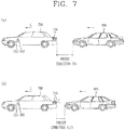
- FIG. 6 is a flowchart illustrating a representative control method in accordance with the present invention
- FIG. 7 is a conceptual view illustrating the control method of FIG. 6 .
- control device 100 may include the brake apparatus 153 for braking the movement of the vehicle, and the rear lamps 154 emitting visible light to the rear of the vehicle 700 when the brake apparatus 153 is activated.
- control device 100 disclosed herein may include the sensing unit 160 that senses at least one of vehicle-related information and surrounding information related to the vehicle.
- the sensing unit 160 may be a sensing unit provided in the control device 100 or the sensing unit 760 provided in the vehicle 700.
- the vehicle-related information may be information related to driving of the vehicle (or a driving state of the vehicle).
- the vehicle-related information may include a driving speed of the vehicle, a weight of the vehicle, a number of persons in the vehicle, braking force of the vehicle, the maximum braking force of the vehicle and the like.
- the surrounding information related to the vehicle may be a state (frictional force) of a road surface on which the vehicle is currently moving, a distance from a front (or rear) vehicle, a relative speed of a front (or rear) vehicle, a curvature of a curve when a driving lane is curved.
- At least one of the vehicle-related information and the vehicle surrounding information is sensed using the sensing unit 160 (S610).
- the processor 170 may detect at least one of the vehicle-related information and the vehicle surrounding information by controlling the sensing unit 160 while the vehicle is driven.
- the detection may be executed always while the vehicle is driven, with a predetermined time interval, or when an object is detected near the vehicle, and the like, but the present invention may not be limited to this.
- the processor 170 may calculate the shortest braking distance of the vehicle 700 using at least one of the detected vehicle-related information and vehicle surrounding information. For example, the processor 170 may calculate the shortest braking distance of the vehicle on the basis of the weight of the vehicle, the driving speed of the vehicle, the maximum braking force of the vehicle and the state of the road surface.
- the processor 170 may also calculate the collision probability of the vehicle.
- the collision probability of the vehicle may be collision probability with a rear vehicle.
- the processor 170 may calculate a relative speed with the rear vehicle, and a relative distance with the rear vehicle through the sensing unit 160. Afterwards, the processor 170 may decide the time to collision (TTC) on the basis of the calculated relative distance and relative speed.
- TTC time to collision
- the collision probability may be decided based on the TTC.
- the TTC may be calculated using the relative speed and the relative distance with the rear vehicle. Also, the TTC may be changed (decided) based on at least one of the driving speed of the vehicle, the weight of the vehicle, the braking force (maximum braking force) of the vehicle, the state of the driving road surface and the shortest braking distance of the vehicle, in addition to the relative speed and the relative distance.
- the collision probability may include collision probability with a front rear vehicle, as well as the collision probability with the rear vehicle. That is, the processor 170 may decide the collision probability (or TTC) with the front vehicle based on the relative speed and relative distance with the front vehicle.
- the processor 170 may decide the collision probability with the front vehicle or the collision probability with the rear vehicle based on at least one of the vehicle-related information and the vehicle surrounding information detected through the sensing unit.
- the collision probability may include departure probability from a currently-driving lane during moving along a curve, as well as the collision probabilities with the front and rear vehicles.
- the departure may include a case where the vehicle is slipped or turned over (or overturned) due to moving along a curve.
- the processor 170 may determine probability that the corresponding vehicle is likely to move out of its driving lane on the basis of at least one of curvature of a curved road surface that the vehicle is currently moving, a state of the road surface, the driving speed of the vehicle and the weight of the vehicle.
- the rear lamps are controlled to output visible light to the rear of the vehicle even though the brake apparatus provided in the vehicle is not operated (S620).
- the preset condition may refer to a condition that the rear lamps 154 emit light even though the brake apparatus 100 is not operated.
- the preset condition may be prestored in the memory 140, 170 or the processor 170 (or controller 770) from the time of producing the control device 100 (or vehicle 700).
- the preset condition may be set or changed by a user.
- the preset condition may be at least one of whether or not the collision probability with the rear vehicle is more than a reference value, whether or not the collision probability with the front vehicle is more than a reference value, or whether or not a lane departure probability of the currently-driven vehicle is more than a reference value.
- the preset condition may include more various conditions.
- the present condition may refer to detailed conditions, such as whether the collision probability with the rear vehicle exceeds a first reference or a second reference higher than the first reference, whether the collision probability with the front vehicle exceeds a first reference or a second reference higher than the first reference, whether the lane departure probability of the currently-driven vehicle exceeds a first reference or a second reference higher than the first reference.
- the preset condition may include presence or absence of other vehicles existing near the vehicle 700, such as whether or not another vehicle is present at the rear of the vehicle 700, whether or not other vehicles are present at both of front and rear sides of the vehicle 700, or whether or not other vehicles are present next the vehicle 700.
- the present condition may refer to a condition which is a combination of at least one of the aforementioned conditions.
- the processor 170 may control the rear lamps 154 to output visible light to the rear of the vehicle even though the brake apparatus 100 is not operated, when the information sensed through the sensing unit 160 corresponds to the preset condition.
- the processor 170 may not allow the rear lamps 154 to output visible light when the information sensed through the sensing unit 160 does not meet the preset condition (e.g., when the collision probability with the rear vehicle is less than the reference value).
- the processor 170 may control the rear lamps 154 to emit the visible light to the rear of the vehicle 700, even though the brake apparatus 153 is not operated, when the information sensed through the sensing unit 160 meets the preset condition (e.g., when the collision probability with the rear vehicle is more than the reference value).
- the processor 170 may control the rear lamps 154 to emit the visible light even though the brake paddle 500 is not pressed (that is, even though the brake apparatus 153 is not operated).
- the processor 170 may control the rear lamps 154 to emit the visible light to the rear of the vehicle 700 even though the brake apparatus 153 is not operated by the AEB system.
- the processor 170 may control brake lamps included in the rear lamps 154 to emit the visible light when the information sensed through the sensing unit 160 meets the preset condition.
- the rear lamps 154 may include separate light sources which are configured to output visible light to the rear of the vehicle even though the brake apparatus 100 is not operated. Afterwards, when the information sensed through the sensing unit 160 meets the preset condition, the processor 170 may control the separate light sources included in the rear lamps 154 to emit the visible light to the rear of the vehicle.
- the present invention can provide a new control method capable of preventing a rear-end collision by warning an accident to a rear vehicle in a manner of controlling the rear lamps to emit light even though the brake apparatus is not operated.
- FIG. 8 is a flowchart illustrating a method of controlling rear lamps in accordance with one embodiment of the present invention
- FIGS. 9A and 9B are conceptual views illustrating the control method of FIG. 8 .
- At least one of the vehicle-related information and the vehicle surrounding information are sensed through the sensing unit 160 (S610). This step will be understood by the description of the step S610 illustrated in FIG. 6 , so detailed description thereof will be omitted.
- the processor 170 may control the rear lamps 154 to output visible light to the rear of the vehicle although the brake apparatus 153 is not operated, when the sensed information corresponds to a preset condition.
- the processor 170 may control the rear lamps 154 to output the visible light in a different manner on the basis of different information sensed through the sensing unit 160 in a state the brake apparatus 153 is not operated.
- the different information may be information which meets the preset condition which is associated with the emission of the rear lamps in spite of the non-operation of the brake apparatus.
- the processor 170 may determine whether or not the sensed information corresponds to a first condition as the preset condition (S622). Afterwards, the processor 170 may control the rear lamps 154 to output the visible light in a first manner when the information sensed through the sensing unit 160 corresponds to the first condition as the preset conditions (S624).
- the processor 170 may determine whether or not the sensed information corresponds to a second condition, different from the first condition as the preset condition, when the sensed information does not correspond to the first condition (S626).
- the processor 170 may control the rear lamps 154 to output the visible light in a second manner, different from the first manner, when the information sensed through the sensing unit 160 corresponds to the second condition, different from the first condition (S628).
- the processor 170 may differently control the rear lamps 154 according to a type of the sensed information (namely, a type of a satisfied condition) when the information sensed through the sensing unit 160 meets a preset condition for controlling the rear lamps 154 to output the visible light without the operation of the brake apparatus 153.
- a type of the sensed information namely, a type of a satisfied condition
- the processor 170 may control the rear lamps 154 to output the visible light in a first manner 900a.
- the first condition may be a case where the collision probability with a vehicle 800 (hereinafter, referred to as'rear vehicle') sensed from the rear of the vehicle 700 is a first value.
- the processor 170 may control the rear lamps 154 to emit the visible light in a second manner 900b, different from the first manner 900a, when the information sensed through the sensing unit 160 corresponds to a second condition, different from the first condition.
- the second condition may be a case where the collision probability with the rear vehicle 800 is a second value greater than the first value.
- FIG. 9A illustrates the example that the visible light output in the first manner or the second manner has a different output angle.
- the visible light output manner of the rear lamp will not be limited to this.
- the rear lamps 154 may be configured to output the visible light in various manners.
- the processor 170 may control not only the light emission angle of the rear lamps 154, but also at least one of an emitting time point of the rear lamps 154, brightness of emitted light of the rear lamps 154, an emission period of the rear lamps 154, an emitting direction of the rear lamps 154 and a color of emitted light of the rear lamps 154.
- the processor 170 may control the rear lamps 154 to output the visible light in the first manner or the second manner which is different from the first manner, by differently controlling at least one (or a combination of more than two) of the light emission angle of the rear lamps 154, the emitting time point of the rear lamps 154, the brightness of emitted light of the rear lamps 154, the emission period of the rear lamps 154, the emitting direction of the rear lamps 154 and the color of emitted light of the rear lamps 154.
- outputting the visible light in the first manner is to output the visible light at a first light emission angle of the rear lamps.
- outputting the visible light in the second manner is to output the visible light at a second light emission angle, different from the first light emission angle.
- outputting the visible light in the first manner is to output the visible light at a first light emission time point of the rear lamps.
- outputting the visible light in the second manner is to output the visible light at a second light emission time point, different from the first light emission time point.
- outputting the visible light in the first manner is to output the visible light with a first brightness.
- outputting the visible light in the second manner is to output the visible light with a second brightness different from the first brightness.
- outputting the visible light in the first manner is to output the visible light at a first light emission period.
- outputting the visible light inn the second manner is to output the visible light at a different light emission period different from the first emission period.
- outputting the visible light in the first manner is to output the visible light in a first emitting direction.
- outputting visible light in the second manner is to output the visible light in a second emitting direction different from the first emitting direction.
- outputting the visible light in the first manner is to output the visible light with a first light color.
- outputting the visible light in the second manner is to output the visible light with a second light color different from the first light color.
- the processor 170 may control the rear lamps 154 to output the visible light in the first manner or the second manner, namely, in various manners.
- the processor 170 may control the rear lamps 154 to output the visible light in a first direction d1 when the information sensed through the sensing unit 160 meets a first condition.
- the first condition for example, may be a case where the rear vehicle 800 with the collision probability exceeding the reference value is located at a first relative position.
- the processor 170 may control the rear lamps 154 to output the visible light in a second direction d2, different from the first direction d1, when the information sensed through the sensing unit 160 meets a second condition, different from the first condition.
- the second condition may be a case where the rear vehicle 800 with the collision probability exceeding the reference value is located at a second relative position different from the first relative position.
- the processor 170 may sense a relative position of the rear vehicle 800 with respect to the vehicle 700 through the sensing unit 160 (e.g., the camera module 200). Afterwards, the processor 170 may control the rear lamps 154 to output the visible light to the rear vehicle based on the sensed relative position.
- the sensing unit 160 e.g., the camera module 200
- the present invention can control the rear lamps to output the visible light to the rear of the vehicle even without the operation of the brake apparatus when the information sensed through the sensing unit meets the preset condition (e.g., when the collision probability exceeds the reference value).
- the present invention can provide the rear lamps which can be controlled to output the visible light in various manners such that a danger can be notified to the rear vehicle in the optimized (or intuitive) manner, and the control device capable of controlling the rear lamps.
- the present invention can provide the rear lamps, which are capable of allowing the rear vehicle to more intuitively recognize the state of the vehicle disclosed herein or the relationship with the vehicle disclosed herein, by being controlled to output the visible light in the different manner according to the type of the condition (preset condition) associated with the emission of the visible light, even without the operation of the brake apparatus, and the control device controlling the rear lamps.
- FIGS. 10 and 11 are conceptual views illustrating one embodiment in accordance with the present invention.
- the processor 170 may control the rear lamps 154 to output visible light to the rear of the vehicle even without the operation of the brake apparatus 153, when information (at least one or a combination of vehicle-related information and vehicle surrounding information) sensed through the sensing unit 160 corresponds to a preset condition.
- the processor 170 may control the rear lamps 154 to output the visible light, even without the operation of the brake apparatus 153, only when the first vehicle 800 is sensed at the rear of the vehicle 700.
- a vehicle existing behind the vehicle 700 is referred to as'rear vehicle' or 'first vehicle.
- the vehicle existing behind the vehicle 700 may include not only a vehicle which is located in a straight line with the vehicle 700 right behind the vehicle 700, but also a vehicle existing behind the vehicle 700 in a diagonal direction.
- the first vehicle (or rear vehicle) 800 should be understood as a concept including every vehicle existing behind the vehicle 700.
- the processor 170 may control the rear lamps 154 to emit light even though the brake apparatus 153 is not operated, when sensed information meets a preset condition, under assumption that the first vehicle 800 is present behind the vehicle 700.
- the existence of the first vehicle 800 behind the vehicle 700 may refer to that the first vehicle 800 is sensed at the rear of the vehicle 700 through the sensing unit 160.
- the processor 170 may control the rear lamps 154 to output the light even without the operation of the brake apparatus 153, under assumption that the first vehicle 800 is sensed at the rear of the vehicle 700.
- the processor 170 may not control the rear lamps 154 to emit light without the operation of the brake apparatus 153, when the first vehicle 800 is not sensed at the rear of the vehicle 700 although the information sensed through the sensing unit 160 meets the preset condition.
- the processor 170 may control the rear lamps 154 to emit light even without the operation of the brake apparatus 153.
- the processor 170 may determine (decide, sense) presence or absence of the first vehicle 800 behind the vehicle 700 by use of the sensing unit 160.
- the processor 170 may sense whether or not the first vehicle 800 is present within a predetermined distance d from the vehicle 700, by using at least one of an ultrasonic sensor, a radar or a LiADAR included in the sensing unit 160, and the camera 200.
- the predetermined distance d may be a distance which can be sensed by a sensor for sensing a vehicle existing behind the vehicle 700.
- the predetermined distance d that the sensing unit 160 can sense the rear vehicle may vary according to at least one of a type of a sensor, a characteristic of the sensing unit 160, a surrounding environment and a driving state of the vehicle 700.
- the processor 170 may determine that the first vehicle 800 is present (sensed) behind the vehicle 700 when the first vehicle 800 is sensed through the sensing unit 160 within the predetermined distance d based on the vehicle 700.
- the processor 170 may control the rear lamps 154 to output the visible light to the rear of the vehicle 700, even without the operation of the brake apparatus 153, when the information sensed through the sensing unit 160 meets a preset condition only under assumption that the first vehicle 800 is sensed at the rear of the vehicle 700.
- the preset condition may be a case where collision probability with the first vehicle 800 sensed at the rear of the vehicle 700 exceeds a reference value.
- the processor 170 may control the rear lamps 154 to output the visible light even without the operation of the brake apparatus 153.
- the processor 170 may calculate a relative distance and a relative speed with the first vehicle 800 sensed at the rear side of the vehicle 700, through the sensing unit 160.
- the processor 170 may decide a time to collision (TTC) based on the calculated relative distance and relative speed.
- TTC time to collision
- the collision probability P may be decided based on the TTC.
- the TTC may refer to a time which is predicted to be taken until the first vehicle 800 sensed at the rear side of the vehicle 700 or a second vehicle 900 sensed from a front of the vehicle 700 collides with the vehicle 700.
- the collision probability P may be inversely proportional to the TTC.
- the collision probability P may increase more.
- the collision probability P may be lowered more.
- the TTC may be reduced when a relative speed between the rear vehicle and the vehicle 700 is fast, a relative distance between the vehicle 700 and the rear vehicle is short, a weight of the vehicle 700 is great or frictional force of a road surface is weak.
- the collision probability P may increase when the relative speed between the rear vehicle and the vehicle 700 is fast, the relative distance between the vehicle 700 and the rear vehicle is short, the weight of the vehicle 700 is great or the frictional force of the road surface is weak.
- the collision probability may refer to probability that the first vehicle 800 sensed at the rear of the vehicle 700 is to collide with the vehicle 700.
- that the collision probability exceeds the reference value may refer to that the probability to collide with the first vehicle 800 (rear vehicle) is higher than a preset probability (reference).
- the processor 170 may calculate the collision probability or collision risk with the rear vehicle based on information sensed through the sensing unit 160. Also, the processor 170 may control the rear lamps 154 to output the visible light to the rear of the vehicle 700 even without the operation of the brake apparatus 153 when it is determined that the collision probability with the rear vehicle is more than a reference value or the collision risk is more than a predetermined level (i.e., when the collision probability exceeds a reference value).
- the reference value may be defined based on at least one of the collision probability or collision risk with the first vehicle 800 (rear vehicle) or the TTC.
- the reference value may be preset or changed by a user or the processor 170.
- the collision probability may vary according to a surrounding state of the vehicle sensed through the sensing unit 160 (e.g., a state of a road surface, frictional force, the weather, a surrounding environment, etc.).
- a surrounding state of the vehicle sensed through the sensing unit 160 e.g., a state of a road surface, frictional force, the weather, a surrounding environment, etc.
- the processor 170 may decide the collision probability P, considering the surrounding state of the vehicle sensed through the sensing unit 160 as well as the TTC.
- the collision probability may increase.
- the collision probability may be lowered.
- the collision probability has been described in relation to the rear vehicle, but the present invention may not be limited to this. That is, the description of the collision probability will be equally/similarly applied even to collision probability with the front vehicle 900 sensed at the front side of the vehicle 700.
- the present invention can calculate collision probability that the rear vehicle 800 and the vehicle 700 are to collide with each other and control the rear lamps 154 to output the visible light to the rear of the vehicle even without the operation of the brake apparatus 153 based on the collision probability (e.g., when the collision probability exceeds the reference value).
- the processor 170 may differently control at least one of an emission angle of the visible light of the rear lamps, an emission time point of the rear lamp, brightness of emitted light of the rear lamps, an emission period of the rear lamps, an emitting direction of the rear lamps, and a light color of the rear lamps, on the basis of the collision probability, when the collision probability exceeds the reference value.
- the processor 170 may control the rear lamps to emit light at a faster time point than a preset time point when the collision probability is higher.
- the processor 170 may control the rear lamps 154 to emit the light at a first time point T1 even without the operation of the brake apparatus 153.
- the collision probability P1 may be collision probability corresponding to a preset condition that the rear lamps emit light even without the operation of the brake apparatus.
- the first time point T1 may be a preset time point, for example.
- the preset time point may be a time point which is preset such that the rear lamps 154 can emit light even without the operation of the brake apparatus 153 when information sensed through the sensing unit 160 meets a preset condition.
- the first time point T1 (preset time point) may be decided (or changed) by the user or under the control of the processor 170.
- the processor 170 may control the rear lamps 154 to emit the light at a second time point T2 faster than the first time point T1 (preset time point) even without the operation of the brake apparatus 153.
- the processor 170 may control the rear lamp 154 to emit brighter light when the collision probability with the first vehicle 800 sensed at the rear of the vehicle 700 is higher.
- the processor 170 may control the rear lamps 154 to emit light with a first brightness B1 when the collision probability is the first value P1.
- the processor 170 may control the rear lamps 154 to emit light with a second brightness B2 higher than the first brightness B1 when the collision probability is the second value P2 greater than the first value P1.
- the processor 170 may control the rear lamps 154 to emit light at a narrower emission angle (or to face a driver of the rear vehicle 800 at a narrower emission angle) when the collision probability with the first vehicle 800 sensed at the rear of the vehicle 700 is higher (this will be understood by equally/similarly applying the description of FIG. 9A .).
- the processor 170 may reduce a lighting period (i.e., the emission period of the rear lamps 154) at which the rear lamps 154 are turned on/off when the collision probability with the first vehicle 800 sensed at the rear of the vehicle 700 is high.
- the processor may also control the rear lamps 154 to emit light with a color associated with the collision probability on the basis of the collision probability with the first vehicle 800 sensed at the rear of the vehicle 700. For example, when the collision probability is a first value, the rear lamps may output visible light with a first color associated with the first value. On the other hand, when the collision probability is a second value different from the first value, the rear lamps 154 may output visible light with a second color associated with the second value.
- the processor 170 may detect a relative position with the first vehicle 800 sensed at the rear of the vehicle 700 through the sensing unit 160. Afterwards, the processor 170 may control an emitting direction of the rear lamps 154 such that visible light can be emitted toward the sensed first vehicle 800 (this will be understood by equally/similarly applying the description of FIG. 9B ).
- the present invention may not be limited to this.
- the present invention may alternatively control the rear lamps in a different manner according to the collision probability with the rear vehicle 800 when the brake apparatus 153 is operated.
- the present invention can control the rear lamps in various manners according to the collision probability with the rear vehicle 800 when the brake apparatus 153 is operated, and the various manners will be equally/similarly understood by the foregoing description.
- control method of the rear lamps according to the present invention may employ various manners without the limit to the aforementioned. That is, if the various manners correspond to the structure of differently controlling the rear lamps according to the collision probability with the rear vehicle, the various manners will be interpreted as belonging to the claims of the present invention.
- the collision probability may be decided based on the TTC which is decided on the basis of the relative distance and relative speed with the first vehicle 800 sensed at the rear of the vehicle 700.
- the present invention can warn the rear vehicle of a risk by turning on the rear lamps even without the operation of the brake apparatus 153, when the collision probability with the rear vehicle exceeds a reference value.
- the present invention can warn a driver of the rear vehicle in an optimized manner and thus remarkably enhance accident prevention by controlling the rear lamps in various manners based on the collision probability exceeding a reference value.
- the present invention can control the rear lamps 154 even without the operation of the brake apparatus 153, by considering a vehicle sensed from the rear of the vehicle 700 and a vehicle sensed from the front of the vehicle 700.
- FIGS. 12 , 13 and 14 are conceptual views illustrating a method of controlling rear lamps, considering both of front and rear vehicles.
- the processor 170 disclosed herein may control the rear lamps 154 to output the visible light even without the operation of the brake apparatus 153, when vehicles are sensed from rear and front sides of the vehicle 700, respectively.
- the processor 170 may control the rear lamps 154 to emit light even without the operation of the brake apparatus 153 when information sensed through the sensing unit 160 corresponds to a preset condition, under assumption that the first vehicle 800 is sensed at the rear of the vehicle 700.
- the processor 170 may also consider a second vehicle 900 sensed at the front of the vehicle 700 as well as the first vehicle 800 sensed at the rear of the vehicle 700.
- the processor 170 may control the rear lamps 154 to output light even without the operation of the brake apparatus 153 when the information sensed through the sensing unit 160 meets a preset condition (i.e., when information related to the first vehicle 800 sensed at the rear of the vehicle 700 and information related to the second vehicle 900 sensed at the front of the vehicle 700 meet the preset condition).
- a preset condition i.e., when information related to the first vehicle 800 sensed at the rear of the vehicle 700 and information related to the second vehicle 900 sensed at the front of the vehicle 700 meet the preset condition.
- the second vehicle 900 is sensed at the front of the vehicle 700 after the first vehicle 800 is sensed at the rear of the vehicle 700. That is, even considering the second vehicle 900 sensed at the front of the vehicle 700, in order for the rear lamps 154 to output light even without the operation of the brake apparatus 153, it should be assumed that the first vehicle 800 is sensed at the rear of the vehicle 700.
- the processor 170 may sense the second vehicle 900 which is present at the front of the vehicle 700, by use of the sensing unit 160.
- the second vehicle 900 present at the front of the vehicle 700 may also be referred to as a front vehicle.
- the processor 170 may sense information related to the second vehicle 900 using the sensing unit 160. For example, the processor 170 may sense a relative distance between the vehicle 700 and the second vehicle 900 (a relative distance with the second vehicle 900), a relative speed between the vehicle 700 and the second vehicle 900 (a relative speed with the second vehicle 900), and the like, through the sensing unit 160.
- the processor 170 may calculate collision probability Q3 with the second vehicle 900, on the basis of the relative distance and the relative speed with the second vehicle sensed at the front of the vehicle 700.
- the processor 170 may calculate the relative distance and the relative speed with the second vehicle 900 sensed at the front of the vehicle 700 through the sensing unit 160, and decide the time to collision (TTC) with the second vehicle 900 based on the calculated relative distance and relative speed.
- TTC time to collision
- the collision probability Q3 may be decided based on the TTC between the vehicle 700 and the second vehicle 900 (front vehicle).
- the collision probability Q3 with the second vehicle 900 may vary according to a surrounding state (e.g., a state of a road surface, frictional force, the weather, a surrounding environment, etc.) of the vehicle 700 sensed through the sensing unit 160.
- a surrounding state e.g., a state of a road surface, frictional force, the weather, a surrounding environment, etc.
- the processor 170 may decide the collision probability Q3 by considering both of the TTC and the surrounding state of the vehicle sensed through the sensing unit 160.
- the processor 170 may sense the first vehicle 800 existing at the rear of the vehicle 700 through the sensing unit 160, and decide collision probability P3 with the first vehicle 800.
- the collision probability with the first vehicle 800 (rear vehicle) will be understood by the foregoing description.
- the collision probability P3 with the first vehicle 800 sensed at the rear of the vehicle 700 is referred to as a first collision probability.
- the collision probability Q3 with the second vehicle 900 sensed at the front of the vehicle 700 is referred to as a second collision probability.
- the processor 170 may decide whether or not to turn on the rear lamps 154 even without the operation of the brake apparatus 153, on the basis of the first collision probability P3 with the first vehicle 800 sensed at the rear of the vehicle 700 and the second collision probability Q3 with the second vehicle 900 sensed at the front of the vehicle 700.
- the processor 170 may control the rear lamps 154 to output light even without the operation of the brake apparatus 153, as illustrated in FIGS. 9A to 11 , on the basis of the collision probability with the first vehicle 800 sensed at the rear of the vehicle 700, irrespective of the second vehicle 900 sensed at the front of the vehicle 700.
- the processor 170 may control the rear lamps 154 to output light even without the operation of the brake apparatus 153, irrespective of the first collision probability P3', P3" sensed at the rear of the vehicle 700.
- the processor 170 may control the rear lamps 154 to output visible light to the rear of the vehicle 700 even without the operation of the brake apparatus 153, irrespective of the first collision probability between the first vehicle 800 and the vehicle 700, so as to notify a warning signal to the first vehicle 800 sensed at the rear of the vehicle 700.
- the processor 170 may control the rear lamps 154 to output the visible light to the rear of the vehicle 700 even without the operation of the brake apparatus 153, irrespective of whether the first collision probability with the first vehicle 800 sensed at the rear of the vehicle 700 does not exceed a reference value (P3') or exceeds a reference value (P3"),.
- the processor 170 may control the rear lamps 154 to output the visible light even without the brake apparatus 153, in response to the first vehicle 800 being sensed at the rear of the vehicle 700.
- the present invention may not be limited to this.
- the processor 170 may alternatively control the rear lamps 154 to emit the visible light, even without the operation of the brake apparatus 153, although the first vehicle 800 is not sensed at the rear of the vehicle 700.
- the processor 170 may differently control at least one of an emission angle of visible light of the rear lamps, an emission time point of the rear lamp, brightness of emitted light of the rear lamps, an emission period of the rear lamps, an emitting direction of the rear lamps, and a light color of the rear lamps, on the basis of the second collision probability with the second vehicle 900 sensed at the front of the vehicle 700.
- the processor 170 may reduce the emission angle of the visible light, set the emission time point ahead, increase the brightness of the emitted light, or shorten the emission period, when the second collision probability Q3 with the second vehicle 900 is high.
- the present invention can provide a control method of preventing a chain collision by controlling the rear lamps to output light even without the operation of the brake apparatus, irrespective of the collision probability with the first vehicle sensed at the rear of the vehicle 700, when the collision probability with the front vehicle exceeds the reference value.
- the processor 170 may sense light output from the second vehicle 900, which is sensed at the front of the vehicle 700, through the sensing unit 160.
- the light emitted from the second vehicle 900 may be light emitted from brake lamps output from the second vehicle 900.
- the processor 170 may also decide a relative distance with the first vehicle 800, which is sensed at the rear of the vehicle 800, through the sensing unit 160.
- the processor 170 may control the rear lamps 154 to emit light even without the operation of the brake apparatus 153, when the emission of light from the second vehicle 900 located at the front of the vehicle 700 is sensed and the relative distance with the first vehicle 800 sensed at the rear of the vehicle 700 is within a reference distance (corresponding to a preset condition).
- the processor 170 may control the rear lamps 154 to output light even without the operation of the brake apparatus 153 when the relative distance with the first vehicle 800 (rear vehicle) is within the reference distance after visible light output from the brake lamps of the second vehicle (front vehicle) 900 is sensed.
- the processor 170 may control the rear lamps 154 to output light even without the operation of the brake apparatus 153 when the visible light output from the brake lamps (rear lamps) of the second vehicle (front vehicle) 900 is sensed in a state that the relative distance with the first vehicle (rear vehicle) 800 is within the reference distance.
- the reference distance may refer to a preset relative distance between the vehicle 700 and the rear vehicle 800 for allowing the rear lamps 154 to output light even without the operation of the brake apparatus 153 when the brake lamps of the front vehicle 900 are turned on (when light emission from the front vehicle is sensed).
- the reference distance may be set or varied by a user setting or the processor 170. Also, the reference distance may be decided or varied based on at least one of the collision probability with the first vehicle and the collision probability with the second vehicle.
- the processor 170 may control the rear lamps 154 to output visible light in a different manner, based on at least one of the second collision probability with the second vehicle (front vehicle) and the first collision probability with the first vehicle (rear vehicle).
- the processor 170 may differently control at least one of an emission angle of visible light of the rear lamps, an emission time point of the rear lamp, brightness of emitted light of the rear lamps, an emission period of the rear lamps, an emitting direction of the rear lamps, and a light color of the rear lamps, on the basis of at least one of the second collision probability with the second vehicle (front vehicle) and the first collision probability with the first vehicle (rear vehicle).
- the present invention can remarkably reduce an accident occurrence by warning the driver of the rear vehicle before the brake apparatus is operated, when the brake lamps of the front vehicle sensed at the front of the vehicle 700 are turned on under assumption that the rear vehicle sensed at the rear of the vehicle 700 exists within the reference distance.
- the processor 170 of the control device 100 may calculate the second collision probability with the second vehicle 900 sensed at the front of the vehicle 700, based on information sensed through the sensing unit 160.
- the processor 170 may output (or generate) a forward collision warning (FCW) when the second collision probability with the second vehicle 900 sensed at the front of the vehicle 700 corresponds to a first value.
- FCW forward collision warning
- the forward collision warning may be output through at least one of the output unit 740 of the vehicle 700, the output unit 150 of the control device 100 and the display device 400.
- the processor 170 may operate the brake apparatus 153 to perform the automatic emergency braking (AEB) when the second collision probability corresponds to a second value greater than the first value.
- AEB automatic emergency braking
- the forward collision warning may be output when the TTC corresponds to a first time t1.
- the AEB may be performed when the TTC corresponds to a second time t2 which is shorter than the first time t1.
- the processor 170 may output the forward collision warning when the collision probability with the front vehicle corresponds to the first value, and perform the AEB when the collision probability with the front vehicle corresponds to the second value greater than the first value (i.e., increases more).
- the processor 170 may sequentially perform the forward collision warning (FCW) and the automatic emergency braking (AEB) as the collision probability increases.
- FCW forward collision warning
- AEB automatic emergency braking
- the rear lamps 154 are not turned on because the brake apparatus 153 is not operated. Also, when the AEB is performed, the rear lamps 154 are turned on because the brake apparatus 153 is operated.
- the rear lamps 154 may output light in response to the AEB being performed.
- the processor 170 may control the rear lamps 154 to emit light even without the operation of the brake apparatus 153 at the generation time point of the forward collision warning (FCW), before the AEB is performed, when the first collision probability with the first vehicle 800 sensed at the rear of the vehicle 700 exceeds the reference value.
- FCW forward collision warning
- the processor 170 may control the rear lamps 154 to output visible light to the rear of the vehicle even though the collision probability with the front vehicle corresponds to the first value generating the forward collision warning (i.e., even without the operation of the brake apparatus 153) when the collision probability with the rear vehicle exceeds the reference value.
- the processor 170 may differently control at least one of an emission angle of visible light of the rear lamps, an emission time point of the rear lamp, brightness of emitted light of the rear lamps, an emission period of the rear lamps, an emitting direction of the rear lamps, and a light color of the rear lamps, on the basis of the first collision probability with the first vehicle 800 sensed at the rear of the vehicle 700 at the generation time point of the forward collision warning (FCW).
- FCW forward collision warning
- the processor 170 may reduce the emission angle, set the emission time point ahead, increase the brightness of the emitted light or shorten the emission period, when the first collision probability with the first vehicle 800 increases more at the generation time point of the FCW.
- the processor 170 may perform the AEB when the collision probability with the front vehicle (second vehicle) 900 corresponds to the second value in the state that the rear lamps 154 emit light even without the operation of the brake apparatus 153. In this instance, the processor 170 may control the rear lamps 154 to output light with higher brightness than a preset brightness when the AEB is performed.
- the present invention can provide a control device capable of warning a risk to a driver of the rear vehicle in advance or at an optimized time point by controlling the rear lamps to output light even without the operation of the brake apparatus at the generation time point of the forward collision warning (FCW), when the collision probability with the rear vehicle exceeds the reference value although the collision probability with the front vehicle is not as high as having to perform the AEB.
- FCW forward collision warning
- the processor 170 may control the rear lamps 154 to output light even without the operation of the brake apparatus 153, irrespective of the first collision probability with the first vehicle 800.
- the processor 170 may control the rear lamps 154 to output light even without the operation of the brake apparatus 153, under assumption that the first vehicle 800 is sensed at the rear of the vehicle 700, when the second collision probability with the second vehicle 900 sensed at the front of the vehicle 700 corresponds to the first value generating the FCW.
- the processor 170 may differently control at least one of an emission angle of visible light of the rear lamps, an emission time point of the rear lamp, brightness of emitted light of the rear lamps, an emission period of the rear lamps, an emitting direction of the rear lamps, and a light color of the rear lamps, on the basis of the second collision probability with the second vehicle 900 (e.g., the TTC with the second vehicle 900) which is calculated from after the generation time point of the FCW.
- the second vehicle 900 e.g., the TTC with the second vehicle 900
- the processor 170 may sense an accident occurred at the front of the vehicle 700 through the sensing unit 160 (or the camera module 200) and the communication unit 110.
- the processor 170 may sense an accident occurred at the front of the vehicle 700 based on specific information (e.g., information notifying the accident occurred at the front) when the specific information is received from another vehicle, from which an accident has occurred, through the communication unit 110.
- specific information e.g., information notifying the accident occurred at the front
- the processor 170 may control the rear lamps 154 to output light even without the operation of the brake apparatus 153.
- the processor 170 may differently control at least one of an emission angle of visible light of the rear lamps, an emission time point of the rear lamp, brightness of emitted light of the rear lamps, an emission period of the rear lamps, an emitting direction of the rear lamps, and a light color of the rear lamps, on the basis of at least one of a relative distance between a sensed accident-occurred location and the vehicle 700, a driving speed of the vehicle 700, the collision probability with the first vehicle 800 and a surrounding state.
- FIG. 15 is a conceptual view illustrating a method of controlling rear lamps based on an external light source in accordance with one embodiment of the present invention.
- the processor 170 may sense a surrounding state of the vehicle 700 through the sensing unit 160.
- the surrounding state of the vehicle 700 may include a relative location of an external light source 1500 (e.g., the sun, a road lamp, a light source of another vehicle, etc.), brightness (or an amount of light) of the external light source 1500, the weather, light transmittance and the like.
- an external light source 1500 e.g., the sun, a road lamp, a light source of another vehicle, etc.
- brightness or an amount of light
- the processor 170 may differently control the brightness of visible light emitted from the rear lamps 154 even without the operation of the brake apparatus 153, on the basis of the location of the first vehicle 800 and the location of the external light source 1500 when the first vehicle 800 is sensed at the rear of the vehicle 700.
- the processor 170 may control the rear lamps 154 to output light with higher brightness than brightness of light that is emitted from the rear lamps 154 when those are not arranged in a straight line.
- the processor 170 may more increase the brightness of the visible light emitted from the rear lamps 154 even without the operation of the brake apparatus 153, when an angle ⁇ between the external light source 1500 and the driving road surface is smaller based on the vehicle 700 (the present invention may not be limited to this, and the processor 170 may increase more the brightness when the angle ⁇ is greater, and the related configuration will be decided or changed by the user).
- the processor 170 may differently control the brightness of the visible light output from the rear lamps 154 even without the operation of the brake apparatus 153.
- the processor 170 may control the rear lamps 154 to output brighter visible light based on the sensing result.
- the present invention can provide the control method capable of controlling the rear lamps to output visible light in an optimized manner, considering the surrounding environment, when the rear lamps emit light even without the operation of the brake apparatus.
- the aforementioned control device 100 may be included in the vehicle 700.
- control device 100 may be equally/similarly applied as the operation or control method of the vehicle 700.
- a control method of a vehicle which includes a sensing unit, a brake apparatus, and rear lamps that emit visible light to the rear of the vehicle in response to an operation of the brake apparatus, may include sensing at least one of information related to the vehicle and surrounding information related to the vehicle through the sensing unit, and controlling the rear lamps to output visible light to the rear of the vehicle even without the operation of the brake apparatus when the information sensed through the sensing unit meets a preset condition.
- Each of the steps may be performed by the controller 770 provided in the vehicle 700.
- controlling the rear lamps may be configured to control the rear lamps to output the visible light in a different manner, on the basis of different information sensed through the sensing unit, in a state that the brake apparatus is not operated.
- controlling the rear lamps may be configured to control the rear lamps to output the visible light in a first manner when the information sensed through the sensing unit corresponds to a first condition as the preset condition.
- controlling the rear lamps may be configured to control the rear lamps to output the visible light in a second manner different from the first manner, when the information sensed through the sensing unit corresponds to a second condition different from the first condition as the preset condition.
- controlling the rear lamps may be performed under assumption that a first vehicle is sensed at the rear of the vehicle.
- controlling the rear lamps may be configured to control the rear lamps to output the visible light even without the operation of the brake apparatus when other vehicles are sensed at both of the front and rear of the vehicle.
- the vehicle 700 may include the control device 100 that controls the rear lamps to output light even without the operation of the brake apparatus when the information sensed through the sensing unit meets a preset condition.
- every function, configuration or control method performed by the control device 100 may be performed by the controller 770 provided in the vehicle 700. That is, every control method described in this specification may also be applied to the control method of the vehicle and the control method of the control device.
- the rear lamps 154 may be configured to output information.
- the information may be at least one of text, a character, a figure, an image, a video and a page.
- the rear lamp 154 may be a device on which information can be output, and implemented by a combination of at least one or at least two of an OLED, an LED and a laser diode (LD).
- OLED organic light-emitting diode
- the processor 170 may output various information through the displayable rear lamps 154.
- the processor 170 may control the rear lamps 154 to output information (text, image or figure) corresponding to the turn-on of the requested turn indicator lamp.
- the processor 170 may output various information through the rear lamps 154 even without the operation of the brake apparatus when information sensed through the sensing unit 160 meets a preset condition.
- the processor 170 may output information (e.g., a bar-like figure image) corresponding to a brake lamp even without the operation of the brake apparatus.
- a preset condition e.g., when collision probability with the rear vehicle exceeds a reference
- the processor 170 may output information (e.g., a bar-like figure image) corresponding to a brake lamp even without the operation of the brake apparatus.
- the processor 170 may output the information in various manners according to a type of the sensed information.
- the bar-like figure image may extend in a widthwise direction of the vehicle.
- the processor 170 may output the bar-like figure image longer as the collision probability with a rear vehicle (or front vehicle) increases more.
- the present invention may not be limited to this, and the information related to the brake lamp may employ various figure images.
- the processor 170 may more increase a size of the figure image output through the rear lamps 154 as the collision probability with the rear vehicle or front vehicle increases more, in case where the collision probability with the rear vehicle (or the front vehicle) exceeds a reference value.
- the present invention may include the rear lamps 154 through which information can be output, and can effectively notify collision probability with the vehicle disclosed herein to a user of a rear vehicle, by varying information (figure image) corresponding to a brake lamp as the collision probability with the rear vehicle or front vehicle increases more.
- the present invention can be implemented as computer-readable codes in a program-recorded medium.
- the computer-readable medium may include all types of recording devices each storing data readable by a computer system. Examples of such computer-readable media may include hard disk drive (HDD), solid state disk (SSD), silicon disk drive (SDD), ROM, RAM, CD-ROM, magnetic tape, floppy disk, optical data storage element and the like. Also, the computer-readable medium may also be implemented as a format of carrier wave (e.g., transmission via an Internet).
- the computer may include the controller 180 of the terminal.
Landscapes
- Engineering & Computer Science (AREA)
- Mechanical Engineering (AREA)
- Transportation (AREA)
- Automation & Control Theory (AREA)
- Chemical & Material Sciences (AREA)
- Combustion & Propulsion (AREA)
- Physics & Mathematics (AREA)
- General Physics & Mathematics (AREA)
- Lighting Device Outwards From Vehicle And Optical Signal (AREA)
Applications Claiming Priority (1)
| Application Number | Priority Date | Filing Date | Title |
|---|---|---|---|
| KR1020160058233A KR101850392B1 (ko) | 2016-05-12 | 2016-05-12 | 차량에 구비된 제어장치 및 이의 제어방법 |
Publications (1)
| Publication Number | Publication Date |
|---|---|
| EP3248841A1 true EP3248841A1 (de) | 2017-11-29 |
Family
ID=58669744
Family Applications (1)
| Application Number | Title | Priority Date | Filing Date |
|---|---|---|---|
| EP17169539.8A Withdrawn EP3248841A1 (de) | 2016-05-12 | 2017-05-04 | Auf einem fahrzeug montierte steuerungsvorrichtung und verfahren zur steuerung des fahrzeugs |
Country Status (4)
| Country | Link |
|---|---|
| US (1) | US10304340B2 (de) |
| EP (1) | EP3248841A1 (de) |
| KR (1) | KR101850392B1 (de) |
| CN (1) | CN107364390B (de) |
Cited By (2)
| Publication number | Priority date | Publication date | Assignee | Title |
|---|---|---|---|---|
| EP3817958A4 (de) * | 2018-07-06 | 2022-03-23 | Eagle Aerospace, Ltd. | Adaptives brems- und richtungssteuerungssystem (abadcs) |
| WO2023244371A1 (en) * | 2022-06-13 | 2023-12-21 | Microsoft Technology Licensing, Llc | Brake alerting based on context detection |
Families Citing this family (23)
| Publication number | Priority date | Publication date | Assignee | Title |
|---|---|---|---|---|
| US9649972B2 (en) * | 2011-04-07 | 2017-05-16 | Pioneer Corporation | System for detecting surrounding conditions of moving body |
| JP6281483B2 (ja) * | 2014-04-17 | 2018-02-21 | 株式会社デンソー | 故障検出システム、情報処理装置、及び車両搭載装置 |
| US10144527B2 (en) * | 2015-03-25 | 2018-12-04 | Skyfront Corp. | Flight controller with generator control |
| WO2018043953A1 (ko) * | 2016-08-31 | 2018-03-08 | 박경준 | 차량 후방 미등 휘도 자동조절 방법 및 장치 |
| DE102016218013A1 (de) * | 2016-09-20 | 2018-03-22 | Robert Bosch Gmbh | Verfahren und Vorrichtung zum automatisierten Anpassen einer Helligkeit wenigstens eines Scheinwerfers für ein Fahrzeug |
| KR101918230B1 (ko) * | 2017-08-16 | 2018-11-14 | 엘지전자 주식회사 | 차량용 램프 및 차량 |
| KR101996852B1 (ko) | 2017-09-29 | 2019-07-08 | 주식회사 만도 | 압력센서를 갖춘 차량용 전자제어식 브레이크 시스템 |
| DE102018200878B3 (de) * | 2018-01-19 | 2019-02-21 | Zf Friedrichshafen Ag | Detektion von Gefahrengeräuschen |
| US11208085B2 (en) * | 2018-02-09 | 2021-12-28 | Mando Corporation | Automotive braking control system, apparatus, and method considering weather condition |
| CN115384486A (zh) | 2018-03-20 | 2022-11-25 | 御眼视觉技术有限公司 | 用于导航主车辆的导航系统和方法 |
| KR102100477B1 (ko) * | 2018-05-04 | 2020-04-13 | 엘지전자 주식회사 | 복수의 자율주행 이동 로봇 |
| KR20210042387A (ko) | 2018-08-14 | 2021-04-19 | 모빌아이 비젼 테크놀로지스 엘티디. | 안전 거리로 항법하기 위한 시스템 및 방법 |
| KR102592825B1 (ko) * | 2018-08-31 | 2023-10-23 | 현대자동차주식회사 | 충돌 회피 제어 장치 및 그 방법 |
| KR20200042660A (ko) * | 2018-10-16 | 2020-04-24 | 현대자동차주식회사 | 차량 디스플레이 제어 장치, 그를 포함한 시스템 및 그 방법 |
| CN109591818A (zh) * | 2018-12-28 | 2019-04-09 | 北京梧桐车联科技有限责任公司 | 一种信息处理方法、交通工具及存储介质 |
| JP7204551B2 (ja) * | 2019-03-19 | 2023-01-16 | 株式会社小糸製作所 | 車両用監視システム |
| CN110053548A (zh) * | 2019-04-29 | 2019-07-26 | 山东交通职业学院 | 一种汽车制动灯控制系统及控制方法 |
| US11267393B2 (en) * | 2019-05-16 | 2022-03-08 | Magna Electronics Inc. | Vehicular alert system for alerting drivers of other vehicles responsive to a change in driving conditions |
| CN110562129B (zh) * | 2019-08-26 | 2021-05-25 | Oppo(重庆)智能科技有限公司 | 车辆信息传输方法、装置、存储介质及车辆 |
| CN113744562B (zh) * | 2020-05-29 | 2023-04-07 | 南京市德赛西威汽车电子有限公司 | 一种基于v2v通信车辆连续追尾预警方法及设备 |
| CN111814970B (zh) * | 2020-06-28 | 2021-02-23 | 盾钰(上海)互联网科技有限公司 | 基于神经网络的实时物理引擎增强计算方法、介质及系统 |
| DE102020120596A1 (de) * | 2020-08-05 | 2022-02-10 | Audi Aktiengesellschaft | Verfahren zum Betrieb einer Heckleuchte eines Kraftfahrzeugs und Kraftfahrzeug |
| CN115633431A (zh) * | 2022-10-19 | 2023-01-20 | 重庆长安汽车股份有限公司 | 车灯节能控制方法、装置、车灯控制设备及存储介质 |
Citations (6)
| Publication number | Priority date | Publication date | Assignee | Title |
|---|---|---|---|---|
| US20060125616A1 (en) * | 2004-11-29 | 2006-06-15 | Song Won M | Method for a changing safety signaling system |
| US20060164221A1 (en) * | 2005-01-18 | 2006-07-27 | Jensen John M | Sensor-activated controlled safety or warning light mounted on or facing toward rear of vehicle |
| DE102005054497A1 (de) * | 2005-11-16 | 2007-05-31 | Daimlerchrysler Ag | Kraftfahrzeug mit Rücklichtern und einer Auffahrwarnvorrichtung |
| US20070152803A1 (en) * | 2005-12-28 | 2007-07-05 | Quinfeng Huang | Method and apparatus for rear-end collision warning and accident mitigation |
| DE102006019495A1 (de) * | 2006-04-26 | 2007-10-31 | Siemens Ag | Warnsignalweitergabe für Kolonnenfahrten |
| FR2995269A1 (fr) * | 2012-09-07 | 2014-03-14 | Peugeot Citroen Automobiles Sa | Dispositif holographique de signalisation pour vehicule |
Family Cites Families (20)
| Publication number | Priority date | Publication date | Assignee | Title |
|---|---|---|---|---|
| KR19980051488U (ko) | 1996-12-30 | 1998-10-07 | 박병재 | 안전거리 유지를 위한 브레이크등 자동점등장치 |
| DE19713884A1 (de) | 1997-04-04 | 1998-10-08 | Bosch Gmbh Robert | Verfahren zur Regelung von Leuchtweite und/oder Leuchtrichtung |
| KR100231573B1 (ko) | 1997-07-18 | 1999-11-15 | 김영귀 | 위험거리 산출기능을 갖는 차량 충돌 경보 제어장치 및 그 방법 |
| JP2000062525A (ja) | 1998-08-24 | 2000-02-29 | Koito Mfg Co Ltd | 車輌用灯具の照射方向制御装置 |
| JP2000233682A (ja) | 1999-02-17 | 2000-08-29 | Koito Mfg Co Ltd | 自動車用ヘッドランプのオートレベリング装置 |
| DE102005059688A1 (de) * | 2005-12-14 | 2007-06-21 | Daimlerchrysler Ag | Kraftfahrzeug mit einer Auffahrwarnvorrichtung |
| DE102007010273A1 (de) | 2007-03-02 | 2008-09-04 | Hella Kgaa Hueck & Co. | Verfahren und Vorrichtung zum Steuern der Lichtabgabe eines Fahrzeugs abhängig vom Verlauf einer Fahrbahn |
| TW201043507A (en) | 2009-06-05 | 2010-12-16 | Automotive Res & Testing Ct | Method for detection of tilting of automobile and headlamp automatic horizontal system using such a method |
| DE102011017697A1 (de) | 2011-04-28 | 2012-10-31 | Robert Bosch Gmbh | Verfahren zur Leuchtweitenregulierung zumindest eines Scheinwerfers eines Fahrzeugs und Lichtsteuergerät |
| DE102011081395A1 (de) | 2011-08-23 | 2013-02-28 | Robert Bosch Gmbh | Verfahren und Steuergerät zur Einstellung einer Leuchtweite eines Scheinwerfers eines Fahrzeugs |
| KR101354131B1 (ko) | 2012-03-15 | 2014-01-24 | 박종국 | 사고 예방 표시 장치, 및 이를 포함하는 자동차 |
| DE102012216088A1 (de) | 2012-09-11 | 2014-03-13 | Robert Bosch Gmbh | Verfahren sowie Auswerte- und Steuereinheit zum Anpassen einer Scheinwerferstrahlgrenze eines Scheinwerferkegels |
| DE102013201850A1 (de) | 2013-02-05 | 2014-08-07 | Hella Kgaa Hueck & Co. | Vorrichtung und Verfahren zur Leuchtweitenregulierung |
| DE102013204076A1 (de) * | 2013-03-11 | 2014-09-11 | Robert Bosch Gmbh | Verfahren zur Kollisionswarnung eines Fahrzeugführers eines auffahrenden Fremd-Fahrzeugs |
| CN104044542A (zh) * | 2013-03-13 | 2014-09-17 | 厦门歌乐电子企业有限公司 | 一种防车辆碰撞的方法及装置 |
| US9796325B2 (en) * | 2013-11-21 | 2017-10-24 | Ford Global Technologies, Llc | Exterior light system for a vehicle |
| CN105793108B (zh) | 2013-12-20 | 2018-10-26 | 金泰克斯公司 | 控制外部车灯 |
| CN103978927B (zh) * | 2014-05-20 | 2016-05-11 | 武汉理工大学 | 一种基于前向防撞系统的汽车刹车尾灯自动控制系统 |
| JP6211043B2 (ja) * | 2015-11-05 | 2017-10-11 | 三菱電機株式会社 | 車両用衝突防止装置 |
| CN105291974A (zh) * | 2015-11-11 | 2016-02-03 | 深圳市精能奥天导航技术有限公司 | 一种预防后车碰撞的主动警示系统和方法 |
-
2016
- 2016-05-12 KR KR1020160058233A patent/KR101850392B1/ko active IP Right Grant
- 2016-07-13 CN CN201610550078.XA patent/CN107364390B/zh active Active
-
2017
- 2017-05-04 EP EP17169539.8A patent/EP3248841A1/de not_active Withdrawn
- 2017-05-12 US US15/593,581 patent/US10304340B2/en active Active
Patent Citations (6)
| Publication number | Priority date | Publication date | Assignee | Title |
|---|---|---|---|---|
| US20060125616A1 (en) * | 2004-11-29 | 2006-06-15 | Song Won M | Method for a changing safety signaling system |
| US20060164221A1 (en) * | 2005-01-18 | 2006-07-27 | Jensen John M | Sensor-activated controlled safety or warning light mounted on or facing toward rear of vehicle |
| DE102005054497A1 (de) * | 2005-11-16 | 2007-05-31 | Daimlerchrysler Ag | Kraftfahrzeug mit Rücklichtern und einer Auffahrwarnvorrichtung |
| US20070152803A1 (en) * | 2005-12-28 | 2007-07-05 | Quinfeng Huang | Method and apparatus for rear-end collision warning and accident mitigation |
| DE102006019495A1 (de) * | 2006-04-26 | 2007-10-31 | Siemens Ag | Warnsignalweitergabe für Kolonnenfahrten |
| FR2995269A1 (fr) * | 2012-09-07 | 2014-03-14 | Peugeot Citroen Automobiles Sa | Dispositif holographique de signalisation pour vehicule |
Cited By (2)
| Publication number | Priority date | Publication date | Assignee | Title |
|---|---|---|---|---|
| EP3817958A4 (de) * | 2018-07-06 | 2022-03-23 | Eagle Aerospace, Ltd. | Adaptives brems- und richtungssteuerungssystem (abadcs) |
| WO2023244371A1 (en) * | 2022-06-13 | 2023-12-21 | Microsoft Technology Licensing, Llc | Brake alerting based on context detection |
Also Published As
| Publication number | Publication date |
|---|---|
| KR101850392B1 (ko) | 2018-04-19 |
| US10304340B2 (en) | 2019-05-28 |
| US20170330464A1 (en) | 2017-11-16 |
| CN107364390B (zh) | 2020-05-05 |
| KR20170127741A (ko) | 2017-11-22 |
| CN107364390A (zh) | 2017-11-21 |
Similar Documents
| Publication | Publication Date | Title |
|---|---|---|
| US10304340B2 (en) | Control device mounted on vehicle and method for controlling the same | |
| US9937948B2 (en) | Steering input apparatus for vehicle and vehicle | |
| US10737689B2 (en) | Parking assistance apparatus and vehicle having the same | |
| US10399480B2 (en) | Control device mounted on vehicle and method for controlling the same | |
| EP3190005B1 (de) | Lampe für ein fahrzeug und fahrzeug damit | |
| US10684620B2 (en) | Vehicle control device mounted on vehicle and method for controlling the vehicle | |
| US10748428B2 (en) | Vehicle and control method therefor | |
| US10155520B2 (en) | Driver assistance apparatus and control method thereof | |
| KR101916993B1 (ko) | 차량용 디스플레이 장치 및 그 제어방법 | |
| KR101768589B1 (ko) | 차량에 구비된 제어장치 및 이의 제어방법 | |
| KR101945809B1 (ko) | 차량 보조 장치 및 차량 | |
| US10112608B2 (en) | Vehicle control device mounted on vehicle and method for controlling the vehicle | |
| US20170038775A1 (en) | Autonomous vehicle | |
| KR101918230B1 (ko) | 차량용 램프 및 차량 | |
| KR20170004144A (ko) | 차량 주행 보조 장치, 이의 동작 방법, 및 이를 포함하는 차량 | |
| US20210385432A1 (en) | Vehicle control device | |
| KR102420922B1 (ko) | 차량 운전 보조장치 및 이를 포함하는 차량 | |
| KR20180106336A (ko) | 카메라장치, 이를 이용한 충돌방지장치 및 충돌방지방법 | |
| KR101894636B1 (ko) | 차량 운전 보조장치 및 이를 포함하는 차량 | |
| KR101796449B1 (ko) | 무게중심조절 기능을 가진 보조장치를 포함하는 이동체 |
Legal Events
| Date | Code | Title | Description |
|---|---|---|---|
| PUAI | Public reference made under article 153(3) epc to a published international application that has entered the european phase |
Free format text: ORIGINAL CODE: 0009012 |
|
| STAA | Information on the status of an ep patent application or granted ep patent |
Free format text: STATUS: REQUEST FOR EXAMINATION WAS MADE |
|
| 17P | Request for examination filed |
Effective date: 20170504 |
|
| AK | Designated contracting states |
Kind code of ref document: A1 Designated state(s): AL AT BE BG CH CY CZ DE DK EE ES FI FR GB GR HR HU IE IS IT LI LT LU LV MC MK MT NL NO PL PT RO RS SE SI SK SM TR |
|
| AX | Request for extension of the european patent |
Extension state: BA ME |
|
| RBV | Designated contracting states (corrected) |
Designated state(s): AL AT BE BG CH CY CZ DE DK EE ES FI FR GB GR HR HU IE IS IT LI LT LU LV MC MK MT NL NO PL PT RO RS SE SI SK SM TR |
|
| STAA | Information on the status of an ep patent application or granted ep patent |
Free format text: STATUS: EXAMINATION IS IN PROGRESS |
|
| 17Q | First examination report despatched |
Effective date: 20191126 |
|
| STAA | Information on the status of an ep patent application or granted ep patent |
Free format text: STATUS: EXAMINATION IS IN PROGRESS |
|
| STAA | Information on the status of an ep patent application or granted ep patent |
Free format text: STATUS: THE APPLICATION IS DEEMED TO BE WITHDRAWN |
|
| 18D | Application deemed to be withdrawn |
Effective date: 20210601 |