EP3248490B1 - Beinbekleidungsstück - Google Patents
Beinbekleidungsstück Download PDFInfo
- Publication number
- EP3248490B1 EP3248490B1 EP17175094.6A EP17175094A EP3248490B1 EP 3248490 B1 EP3248490 B1 EP 3248490B1 EP 17175094 A EP17175094 A EP 17175094A EP 3248490 B1 EP3248490 B1 EP 3248490B1
- Authority
- EP
- European Patent Office
- Prior art keywords
- leg garment
- stimulus
- leg
- region
- garment
- Prior art date
- Legal status (The legal status is an assumption and is not a legal conclusion. Google has not performed a legal analysis and makes no representation as to the accuracy of the status listed.)
- Active
Links
Images








Classifications
-
- A—HUMAN NECESSITIES
- A41—WEARING APPAREL
- A41D—OUTERWEAR; PROTECTIVE GARMENTS; ACCESSORIES
- A41D1/00—Garments
- A41D1/06—Trousers
- A41D1/08—Trousers specially adapted for sporting purposes
-
- A—HUMAN NECESSITIES
- A41—WEARING APPAREL
- A41D—OUTERWEAR; PROTECTIVE GARMENTS; ACCESSORIES
- A41D13/00—Professional, industrial or sporting protective garments, e.g. surgeons' gowns or garments protecting against blows or punches
- A41D13/0015—Sports garments other than provided for in groups A41D13/0007 - A41D13/088
-
- A—HUMAN NECESSITIES
- A41—WEARING APPAREL
- A41D—OUTERWEAR; PROTECTIVE GARMENTS; ACCESSORIES
- A41D31/00—Materials specially adapted for outerwear
- A41D31/04—Materials specially adapted for outerwear characterised by special function or use
- A41D31/18—Elastic
-
- A—HUMAN NECESSITIES
- A41—WEARING APPAREL
- A41B—SHIRTS; UNDERWEAR; BABY LINEN; HANDKERCHIEFS
- A41B11/00—Hosiery; Panti-hose
- A41B11/003—Hosiery with intermediate sections of different elasticity
Definitions
- the present invention relates to a leg garment.
- legwear includes stockings, socks, and any other type of hosiery, including tights, and pants, such as three quarter length shorts and pants, leggings and leggings (both short and long).
- the US 2010/130903 A1 discloses a leg garment according to the preamble of claim 1.
- the present invention has for its object to provide such a leg garment, which is adapted to reduce the risk of injury to the wearer of the leg garment, especially in sports activities, and to compensate for possible functional dysbalances of the musculoskeletal system of the wearer and a performance optimization in to achieve sensory activity.
- the present invention is based on the concept of exerting a proprioreceptive stimulating effect on the wearer of the leg garment by means of the stimulus inducing structure, whereby the proprioreceptive stimulating effect of the stimulus inducing structure is enhanced by the simultaneous compression action of the leg garment on the leg of the wearer.
- the stimulation of the proprioceptors not only reduces the risk of injury, especially in sports activities, but also a balance of functional dysbalances of the musculoskeletal system can be achieved.
- An improvement in the body stability and / or a reduction of dysbalances of the musculoskeletal system cause a balanced, symmetrical posture of the wearer, resulting in a lower stress, a delayed fatigue tendency and a prolonged well-being tendency of the wearer.
- the proprioreceptive stimulation of the musculature of the wearer of the leggings results in a reduction of the risk of injury due to incorrect movements and overstretching as well as an optimization and synchronization of the body coordination of the wearer.
- the legwear piece according to the invention makes it possible to use the positive effect of proprioceptive stimulation, in particular in the broad sports sector, for prophylactic applications, for example in the business sector, and / or in the wellness or cosmetic sector.
- the leg garment according to the invention is a clothing worn close to the body, which makes possible in a simple and easily applicable manner effective proprioreceptive stimulation of the musculature of the wearer.
- the legwear piece according to the invention can in particular be designed as a knee-length stocking, as a sock or as leggings.
- the proprioceptive stimulation desired according to the invention is achieved, in particular, by targeted attachment of at least one stimulus-inducing structure with functional elements which exert a sensory irritant effect on the musculature of the wearer, on the inside of the leg garment facing the wearer's body.
- the stimulus-inducing structure is preferably disposed at a position of the leg garment associated, in the worn state of the leg garment, with a portion of the leg of the wearer having as high a proprioceptor density as possible.
- Preferred regions of the stimulus-inducing structure are the progressions of the myofascial chains, which extend from the foot over the leg area, spiraling up to the head.
- leg garment In a preferred embodiment of the leg garment according to the invention, it is provided that the sole region of the leg garment remains free of stimulus-inducing structures in order to reliably avoid potential false stimulation at this point.
- the compression effect of the compression region enhances the proprioceptive stimulating effect of the stimulus-inducing structure, it is favorable if the stimulus-inducing structure is at least partially, preferably substantially completely, disposed in the at least one compression region of the leg garment.
- At least one stimulus-inducing structure in the worn state of the leg garment is separated by a cover from the skin of the wearer.
- At least one stimulus-inducing structure is covered by a textile construction.
- the compression region of the leg garment preferably comprises an elastically yielding material.
- the compression region of the leg garment comprises a knitted or knitted fabric.
- the compression region of the leg garment comprises at least one elastic yarn, for example spandex.
- the compression region can have a substantially constant course of the compression strength.
- the compression region has a gradual course of the compression strength.
- the compression region when the compression region is arranged in the shaft region of the leg garment, it is advantageous if the compression strength in the compression region increases, especially towards a waist region of the leg garment.
- the compression strength increases upward, in particular in the direction of a waist region of the leg clothing piece.
- the compression region preferably does not include the knee region of the leg garment.
- the leg garment comprises a region in the worn state above the knee of the wearer of the leg garment, in particular a thigh region, it is advantageous if the compression strength in this region of the leg garment is upward, that is towards the wearer's torso Leg garment, decreases.
- the maximum compression strength in the compression region is preferably at least about 7 mm Hg, more preferably at least about 10 mm Hg.
- the maximum compression strength in the compression region is at most approximately 32 mm Hg, in particular at most approximately 25 mm Hg.
- At least one compression region comprises at least part of a midfoot region, at least part of an ankle region and / or at least a part of a shaft region of the leg garment.
- the proprioreceptive stimulating effect of the stimulus-inducing structure is achieved by the stimulus-inducing structure comprising at least one stimulus-inducing functional element.
- the stimulus-inducing structure comprises a plurality of such functional elements.
- the various functional elements of the stimulus-inducing structure can be isolated from one another or, in particular at end regions of the functional elements, adjoin one another.
- At least one functional element of a stimulus-inducing structure is formed as a protrusion.
- the functional elements can be formed by attaching or incorporating materials or constructions into a base body, in particular a basic knit, of the legwear piece, which leads to a punctiform increase in the textile structure, which becomes noticeable when wearing the leggings as a local pressure point.
- the functional elements are firmly connected directly to a textile material of the leg garment.
- the stimulus-inducing structure can be optimally positioned on the leg garment.
- the functional elements basically all materials and constructions are suitable, which lead to a local pressure point on the skin of the wearer when wearing the leg garment. Basically, these may be both hard, compact materials, such as wood, plastic of any kind or metal, as well as soft, flexible, plastic materials, such as silicone-based plastics, polytetrafluoroethylene (PTFE) -based or based on polyurethane (PUR).
- At least one functional element contains an elastic, a thermoplastic and / or a thermosetting polymer.
- at least one functional element contains a silicone, a PVC-based plastisol, a polyurethane-based polymer and / or a polytetrafluoroethylene-based polymer.
- At least one functional element comprises a knitted portion of the leg garment that differs in terms of its type of binding from a knitted portion of the leg garment adjacent to the functional element and is formed as a plush.
- the knitted portion of the functional element contains a hot melt adhesive thread.
- Such a hot-melt adhesive thread may comprise, for example, polyester and / or copolyamide, preferably formed essentially entirely of polyester and / or copolyamide.
- the hot melt adhesive material from which such a hot melt adhesive thread is formed may have, for example, a softening temperature of 50 ° C or higher, especially 80 ° C or higher.
- the region of the legwear piece in which the functional element has been produced can be subjected to a heat treatment, by means of which the hotmelt adhesive material is heated to a temperature above its softening temperature.
- the treatment temperature may be 70 ° C. or higher, in particular 100 ° C. or higher.
- the heat treatment can be carried out, for example, by tumbling, shaping or applying hot air.
- At least one functional element preferably a multiplicity of functional elements, has a teardrop-shaped or knob-shaped form.
- At least one functional element of a stimulus-inducing structure has a locally limited, in particular substantially punctiform, design.
- all functional elements of at least one stimulus-inducing structure are locally limited, in particular substantially point-shaped.
- At least one functional element has a maximum extent (along the main body of the leggings) of at most approximately 1.0 cm, preferably at most approximately 0.7 cm, in particular at most approximately 0.6 cm, particularly preferably at most approximately 0.3 cm. It is particularly favorable if all functional elements of a stimulus-inducing structure have such a greatest extent.
- At least one functional element has a maximum extent (along the base body of the leg garment) of at least approximately 0.2 cm. It is particularly favorable if all functional elements of a stimulus-inducing structure have such a maximum extent.
- a functional element of a stimulus-inducing structure may, for example, have a substantially circular outer contour.
- Each functional element in particular each locally limited functional element, may in principle also have any other outer contour, for example a polygonal outer contour, a triangular outer contour, a square outer contour, a rectangular outer contour or an angular outer contour.
- Locally limited functional elements differ from linear elements that have a large dimension in one dimension and large area elements that have a large extent in two dimensions.
- a stimulus-inducing structure which are in particular web-shaped, adjoin one another at their end regions and thus form a coherent stimulus-inducing structure, such a stimulus-inducing structure can be in particular honeycomb-shaped.
- the height of at least one functional element ie its extension perpendicular to the main body of the leg garment, around which the Functional element protrudes toward the skin of the wearer, is preferably at least about 0.1 cm, in particular at least about 0.2 cm.
- the height of at least one functional element is at most approximately 0.4 cm, in particular at most approximately 0.3 cm.
- the Shore A hardness of the material of at least one functional element is at least approximately 20, preferably at least approximately 30.
- At least one functional element is formed of a material having a Shore A hardness of at most about 90.
- the Shore A hardness can be determined according to DIN 53505 or DIN EN ISO 868.
- At least one functional element is formed from a material having a Shore D hardness of at least approximately 20.
- the Shore D hardness is preferably at most about 90.
- the Shore D hardness can be determined according to DIN 53505 or DIN ISO 7619-1.
- At least one functional element is fixed to a base body of the leg garment.
- all functional elements are fixed to the main body of the leg garment.
- At least one functional element is directly connected to a textile material of the garment.
- the stimulus-inducing structure formed by the functional elements can be optimally positioned on the leg garment.
- At least one stimulus-inducing structure comprises at least one carrier element, on which a plurality of functional elements are formed.
- the plurality of functional elements are formed integrally with the carrier element.
- At least one support element can be permanently fixed to a base body of the leg garment.
- At least one carrier element is releasably connected to a main body of the leg garment.
- stimulus-inducing functional elements can be connected in a separate process to form a coherent unit, and this unit can be fixed to the main body of the leg garment, for example by gluing, welding or sewing.
- the carrier element may be a prefabricated part that has a plurality of functional elements.
- a stimulus-inducing structure may be formed by such a carrier element or by a plurality of such carrier elements.
- the outer contour of such a support element may correspond to the outer contour of an entire stimulus-inducing structure.
- the carrier element may be formed, for example, as a textile construction.
- a carrier element which preferably comprises the stimulus-inducing functional elements of an entire stimulus-inducing structure and is preferably based on a textile construction, can be flexibly and / or releasably connected to the main body of the leg garment by known manufacturing techniques.
- the leg garment may be provided with indicia offset in color from a base material of the leg garment which serves as a guide to the wearer of the leg garment when donning the leg garment to achieve optimum positioning of the stimulus-inducing structures on the body of the wearer.
- At least one stimulus-inducing structure in the worn state of the leg garment at least partially with the Muscle / tendon band tibialis anterior and / or overlapped with the peronei muscles and tendons, for example, with the muscle / tendon band Peroneus longus, the wearer of the leg garment.
- the leg garment corresponds to an outer contour of at least one stimulus-inducing structure substantially an outer contour of the muscle gastrocnemius muscle, the muscle vastus medialis, the muscle vastus lateralis muscle, the muscle gluteus medius muscle, the muscle gluteus minimus muscle, the fiber tract iliotibial tract, Muscle of the rectus femoris muscle and / or the posterior flexor muscles of the thigh.
- two stimulus-inducing structures are arranged in the knee area of the leg garment, which are arranged in the worn state of the leg garment on opposite sides of the patella of the wearer of the leg garment.
- a stimulus-inducing structure may be arranged on the inside of the knee area and an opposing stimulus-inducing structure to be arranged on the outside of the knee area.
- At least one of these stimulus-inducing structures is preferably formed arcuate. In particular, it can be provided that both of these stimulus-inducing structures are arc-shaped.
- the stimulation by means of these stimulus-inducing structures stimulates the stabilization of the knee joint of the wearer of the leg garment.
- a stimulus-inducing structure corresponding to an outer contour of the muscle gluteus maximus muscle, the muscle gluteus minimus muscle and / or the iliotibial fiber tract is preferably arranged in the worn state of the leg garment on the outside of the thigh from the hip to just above the musculus vastus lateralis muscle in the knee area ,
- a stimulus-inducing structure corresponding to the outer contour of the musculus rectus femoris muscle is arranged in the worn state of the leg garment at the front of the thigh.
- stimulus-inducing structures are arranged in the worn state of the leg garment on the left and right of the Achilles tendon.
- Procroreceptive pacing results in improved synchronization of the muscles recruited for walking or running.
- leggings In order to achieve selective proprioceptive stimulation and to avoid potential false stimulation, it is beneficial if the leggings have at least two stimulus-inducing structures separated by a region having no stimulus-inducing structure.
- the stimulus induction zones in which the stimulus-inducing structures are arranged at most half, preferably at most one third, in particular at most a quarter, of the inner surface of the leg garment facing the wearer's body in the worn state of the leg garment cover.
- At least one stimulus-inducing structure is arranged outside the waist region of the leg garment.
- At least one stimulus-inducing structure is arranged in a stimulus induction zone is, which is at least partially bounded by a boundary strip.
- Such a boundary strip can stand out in particular by a contrasting with the color of the main body of the leg garment color from the body.
- the leg garment is preferably provided with a mark extending substantially along a longitudinal medial plane of the leg garment in the leg garment worn, which is an inner side of the leg garment from an outer side of the leg garment Legwear separates.
- the "inner side” of the leg garment is the side of the leg garment facing the other leg of the wearer when the leg garment is worn.
- the "outer side" of the leg garment is accordingly the side of the leg garment facing away from the respectively other leg of the wearer when the leg garment is worn.
- At least one stimulus-inducing structure of the legwear piece according to the invention is preferably substantially strip-shaped.
- such a strip-shaped stimulus-inducing structure has a width (that is to say an extent perpendicular to its longitudinal extension) of at most approximately 4 cm, in particular of at most approximately 2 cm.
- the stimulus-inducing structure is preferably firmly connected to a main body, in particular a basic knit or a basic knit, of the leg garment.
- the surface density of the functional elements within a stimulus inducing structure of the leg garment is preferably at least about 1 per cm 2 , more preferably at least about 4 per cm 2 , most preferably at least about 8 per cm 2 .
- the surface density of the functional elements within a stimulus-inducing structure is preferably at most about 25 per cm 2 , more preferably at most about 16 per cm 2 , more preferably at most about 12 per cm 2 .
- An in Fig. 1 in a version to be worn on the right leg and in the Fig. 2 and 3 in a legged version to be worn on the left leg, designated 100 as a whole, comprises a waistband region 102 at the upper end of the stocking, a shank region 104 downwardly adjacent the waistband region, and a foot region adjacent the shaft region 104 downwardly and forwardly 106, which encloses the foot of the wearer in the worn state.
- the lower half of the foot region 106 of the sock 100 forms a sole region 108, which comprises a lower half 110 of a heel region 112, a lower half 114 of a toe region 116 and an intermediate region 118 located between the heel region 112 and the toe region 116.
- Fig. 1 shown right stocking and in the Fig. 2 and 3 shown left stocking are formed with respect to a longitudinal center plane 120 of the respective stocking mirror images of each other and form a pair of matching stocking.
- the two stockings can be provided with a, preferably knitted, mark, from which it can be seen whether the respective stocking is the left or the right stocking of the pair.
- the side facing away from the respectively other leg of the wearer when wearing the stocking 100 is referred to in this description as the "outer side" of the respective stocking 100.
- the outer side of the left stocking is in Fig. 3 shown.
- the side of the stocking 100 facing the respectively other leg of the wearer when wearing the stocking 100 is referred to in this description as the "inner side" of the stocking 100.
- the outer side and the inner side of a sock 100 are separated from each other by the longitudinal center plane 120 of the sock 100 in question.
- the side of the stocking 100 (“left side of the fabric") facing the leg of the wearer when wearing the stocking 100 is referred to in this specification as the “inside” of the stocking 100 in question.
- the side of the stocking 100 (“right side of the garment") facing away from the leg of the wearer when wearing the stocking 100 is referred to in this description as the "outside” of the stocking 100 in question.
- the shaft region 104 and the foot region 106 of the sock 100 are formed, preferably continuously, from a basic knit 122 which comprises one or more ground threads.
- the ground yarn or threads may be formed of any material, for example of a natural fiber or a man-made fiber.
- the sock 100 may be provided with one or more padding.
- the foot region 106 of the stocking 100 may be provided with a foot pad 124 which extends from the toe region 116 over the intermediate region 118 of the sole region 108 to the heel region 112 and over a toe region 126.
- this foot padding 124 is preferably formed asymmetrically with respect to the longitudinal center plane 120 of the foot region 106 of the sock 100.
- a region of the foot region 106 may be excluded from the foot padding 124, which in the worn state of the stocking 100 is located in the region of the inner arch of the wearer of the stocking 100. Since the wearer of the stocking 100 does not occur with this area of the inner arch of the foot during walking, the outer contour of the foot padding 124 on the underside of the foot region 106 substantially corresponds to the outer contour of the foot contact surface of the wearer of the stocking 100.
- a region 128 projecting in a wedge shape towards the tip of the foot region 106 may be excluded from the foot padding 124.
- This wedge-shaped recessed area 128 is preferably formed asymmetrically with respect to the longitudinal center plane 120 of the foot area 106; In particular, the forward facing tip 130 of this wedge-shaped recessed area 128 lies on the inner side of the stocking 100.
- the toe region 116 provided with the foot padding 124 may also be formed asymmetrically with respect to the longitudinal mid-plane 120 of the foot region 106 in order to allow a better adaptation of the stocking 100 to the course of the toes of the wearer of the stocking 100.
- an inner edge portion 132 of the toe area 116 disposed on the big toe side of the wearer is inclined at a smaller angle to the longitudinal center plane 120 of the foot area 106 than an outer edge portion 134 of the one of the wearer's small toe Toe area 116.
- a plurality of channels 136 extending essentially parallel to the longitudinal center plane 120 of the foot region 106 may be provided within the outer contour of the foot padding 124, in the region of which the stocking 100 has a lower degree of reinforcement than in the areas of the foot padding 124 surrounding the channels 136.
- the stocking 100 in the region of the channels 136 comprises only the basic knit 122, but no additional reinforcing threads.
- the foot pad 124 may include one or more reinforcing threads, which may be formed of any material.
- the reinforcing threads or the reinforcing threads of the foot padding 124 form plush loops, which are preferably arranged on the "left side of the goods", ie on the inside of the stocking 100.
- the sock 100 may further include an Achilles tendon padding 138 adjacent the leg pad 124 of the heel region 112 and extending upwardly therefrom along an upper edge.
- the Achilles tendon padding 138 may also comprise one or more reinforcing threads, which may be formed of any material.
- the degree of reinforcement of the Achilles tendon padding 138 corresponds to the degree of reinforcement of the foot padding 124.
- the sock 100 further includes one or more compression regions 142 in which the sock 100, when worn, exerts a compressive action on the leg of the wearer.
- This compression effect can be achieved in particular by the incorporation of one or more elastic threads into the basic knit 122 of the stocking 100.
- the or the elastic threads may in particular comprise elastane.
- the stocking 100 may include a first compression region 142a that extends downwardly from the upper edge 144 of the shaft portion 104 to a lower edge 146 of the first compression portion 142a.
- the lower edge 146 of the first compression region 142a preferably lies above an ankle region 148 of the stocking 100, which, in the worn state of the stocking 100, rests against the ankle of the wearer.
- the lower edge 146 of the first compression region 142a extends at least approximately 1 cm, preferably at least approximately 2 cm, above the ankle region 148.
- the stocking 100 may include a second compression region 142b that extends from a forward edge 150 in the midfoot region to a rearward edge 152 in the region of the ankle of the wearer (in the worn state).
- This second compression portion 142b serves to stabilize and support both the arch of the foot and the ankle of the wearer.
- the toe area 116 receives comfort reasons preferably no compression effect.
- the lower edge 146 of the first compression portion 142a and the rear edge 152 of the second compression portion 142b are spaced from each other.
- the compression regions 142a, 142b directly adjoin one another and form a contiguous compression region of the sock 100.
- the compression strength in the first compression region 142a and / or in the second compression region 142b is preferably at least approximately 10 mm Hg and / or at most approximately 32 mm Hg, in particular at most approximately 25 mm Hg.
- the compression strength may be constant in the first compression region 142a and / or in the second compression region 142b over the respective compression region 142a, 142b or may also have a gradient.
- the first compression region 142a may have a compression curve in which the compression strength decreases from bottom to top.
- the compression strength at the upper edge 144 of the first compression region 142a is from about 60% to about 80% of the compression strength at the lower edge 146 of the first compression region 142a.
- the stocking 100 includes one or more irritation induction zones 154, each provided with a stimulus-inducing structure 156.
- Each stimulus-inducing structure 156 comprises functional elements 158 which, in the worn state of the stocking 100, cause a sensory irritation and a proprioreceptive stimulation of the musculature of the wearer.
- This stimulation leads to increased muscle activity and improves the synchronization of the wearer.
- the functional elements 158 are preferably designed as elevations, which are arranged on the inside of the stocking 100 and act directly on the skin of the wearer.
- the functional elements 158 can be formed, in particular in the form of elevations, by textile materials and / or textile constructions which lead to the formation of a protrusion protruding to the skin of the wearer, for example by means of plush.
- the functional elements 158 have a maximum extension of at most approximately 0.7 cm.
- the maximum extent of the functional elements 158 is at least approximately 0.2 cm.
- the height of the functional elements 158 is preferably at least approximately 0.1 cm, in particular at least approximately 0.2 cm.
- the height of the functional elements 158 is at most approximately 0.4 cm, in particular at most approximately 0.3 cm.
- the functional elements 158 are formed from a material having a Shore A hardness of at least about 30.
- the Shore A hardness of the material of the functional elements 158 is at most about 90.
- the Shore A hardness can be determined according to DIN 53505 or DIN EN ISO 868.
- the functional elements 158 may be formed from a material having a Shore D hardness of at least about 20 and / or at most about 90.
- the Shore D hardness can be determined according to DIN 53505 or DIN ISO 7619-1.
- the stimulus-inducing structures 156 are preferably arranged in stimulus induction zones 154 arranged along the muscle progressions.
- the stocking 100 may include an anterior stimulus induction zone 154a that extends along the tibialis anterior muscle / tendon ligament and / or a posterior stimulus induction zone 154b that extends along the peroneus longus muscle / tendon ligament.
- the stimulus-inducing structure 156 of the anterior stimulus induction zone 154a for stimulating the tibialis tendon ligament is located on the outer side of the stocking 100, begins just below the knee of the wearer (as worn) and extends above the wearer's outer ankle to maximally the instep , The width of the front stimulus induction zone 154a decreases from top to bottom.
- the front stimulus induction zone 154a terminates at a tip 160 on the wearer's footrest.
- the stimulus-inducing structure 156 of the rear stimulus induction zone 154b for stimulation of the peroneus longus muscle / tendon ligament is also located on the outer side of the stocking 100 and is located behind the front stimulus induction zone 154a and spaced therefrom.
- the rear irritation induction zone 154b preferably starts just below the knee of the wearer (in the worn state) and extends on the posterior side of the ankle where it terminates at a tip 162.
- the width of the stimulus induction zones 154 is preferably such that the individual anatomical differences of the various wearers are taken into account.
- the width of the front stimulus induction zone 154a and / or the rear stimulus induction zone 154b is preferably at least about 2 cm and / or preferably at most about 4 cm at its upper end.
- the functional elements 158 of the stimulus induction zones 154 are located on the inside of the stocking 100, they need not be visible from the outside of the stocking 100 (as shown in FIGS Fig. 1 to 3 is shown).
- the stimulus induction zones 154 are bounded at least in sections by a limiting strip 164.
- This boundary strip 164 preferably lifts off from the base fabric 122 by a color contrasting with the color of the base fabric 122.
- the delimiting strip 164 is formed by knitting one or more contrasting colored threads into the base knit 122.
- the stimulus induction zones 154 in the worn state should be positioned as precisely as possible on the respective associated muscle and tendon ligaments.
- the sock 100 preferably includes a marker strip or line 166 that extends substantially midway from the toe portion 116 straight to the waistband portion 102 of FIG Stocking 100, along the longitudinal center plane 120 of the stocking 100, runs and can serve as a positioning aid for the wearer when putting on the stocking 100.
- the marking line 166 preferably stands out from the color of the base knit 122 by a contrasting color.
- the marker line 166 is formed by knitting one or more contrasting colored threads into the base fabric 122.
- the stimulus-inducing structures 156 of the stimulus induction zones 154a, 154b are located for the most part, preferably more than 90%, in one of the compression regions 142 of the stocking 100. This ensures that the local compressive stress on the skin of the wearer is reinforced by the functional elements 158 of the stimulus-inducing structures 156 due to the large-area compression effect of the compression regions 142. By combining the Compression effect of the compression regions 142 on the one hand and the local functional elements 158 of the stimulus-inducing structures 156 on the other hand thus a particularly effective proprioreceptive stimulation of the musculature of the wearer is effected.
- the surface density of the functional elements 158 in the stimulus induction zones 154 is preferably at least about 1 per cm 2 , more preferably at least about 4 per cm 2 , most preferably at least about 8 per cm 2 .
- the surface density of the functional elements 158 in the stimulus induction zones 154 is at most approximately 25 per cm 2 , in particular at most approximately 16 per cm 2 , particularly preferably at most approximately 12 per cm 2 .
- the functional elements 158 of the stimulus-inducing structures 156 are illustrated schematically in a substantially circular manner.
- FIG Fig. 4 A single functional element 158 with a circular edge is shown in FIG Fig. 4 shown.
- the functional elements 158 can also have any other outer contours, for example a triangular outer contour (see FIG Fig. 5 ), a square outer contour (see Fig. 6 ), a rectangular outer contour (see Fig. 7 ) or an angular outer contour (see Fig. 8 ).
- a stimulus-inducing structure 156 is not completely isolated from one another, but adjoin one another at end points and thus form a coherent stimulus-inducing structure 156, for example a honeycomb stimulus-inducing structure 156 as shown in FIG Fig. 9 is shown in sections.
- the functional elements 158 do not cover the entire surface of the respective stimulus induction zone 154, but remain between the functional elements 158 of the functional elements 158 free surface portions 168, which in the worn state of the stocking 100 do not put pressure on the skin of the wearer.
- the functional elements 158 of the stimulus-inducing structures 156 may be formed in a leg garment comprising a textile base body 170 in the form of a basic knit 172, in particular by the fact that the functional element 158 in question comprises a knitted area 174 which, in terms of its type of binding, is adjacent to a knitted area 176 of the basic knit 172 differs.
- knitted area 174 of the functional element 158 which in the illustrated embodiment comprises seven wales and six courses, is an additional plush thread 182 (in Fig. 10 provided with puncture) in Plüschitati knitted into the basic knit 172.
- the knitted area 174 of the functional element 158 is thus selectively formed as a plush (sandwich or normal plush).
- This plush forms a structure raised above the basic knit 172.
- the plush can be knitted in ergonomic technique (placed in forms) or selected.
- the shape of the knitted area 174 is basically arbitrary; In particular, each of these in the Fig. 4 to 9 shown outer contours are used.
- Each functional element 158 comprising a knitted area 174 with a raised surface is separated from the other functional elements 158 by the plush yarn 182 additionally made from a knitting machine base system or from one or more embroidery systems of the knitting machine, which forms stitches together with the base fabric 172 , knitted.
- the additional plush thread 182 generates ground loops having plush loops 184 facing inwardly (ie, in the worn state of the leg garment toward the wearer's skin).
- the additional plush thread 182 is introduced into a surface to be determined freely by a pattern image and cut, for example, by a saw and an upper blade of the knitting machine so that individual functional elements 158 arranged separately from one another are formed.
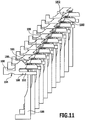
- a knitting machine having needles 186 and plush boards 188 as shown in FIG Fig. 11 are shown schematically.
- plush boards 188 are sandwich plush boards. Alternatively, however, other deburring boards, in particular normal plush boards, can be used.
- Each of the plush boards 188 includes a foot 190, a shank 192, a display 194 disposed between the shank 192 and the foot 190, a sinker beak 196 disposed above the shank 192, a throat 198 located above the sinker beak 196, and a throat 198 located above the throat 198 Plush nose 199 on.
- plating thread 180 and plush thread 182 over plush boards 188 and needles 186 is also off Fig. 11 to see.
- the ground yarn 178 extends immediately under the plating yarn 180 and is shown in FIG Fig. 11 covered by the plating thread 180.
- plush thread 182 is placed on the outside of the fabric.
- any desired materials and combinations of materials can be used as the main thread 178 and as the plating thread 180 of the basic knit 172.
- a synthetic fiber material for example made of polypropylene
- a hot-melt adhesive material for example of polyester
- a polypropylene filament yarn (eg, a dtex 84 / F25 / 2 twisted yarn, two filaments of 25 filaments each) having a comparatively low melting point in the range of 165 ° C to about 175 ° C and a softening temperature in the range from 150 ° C to 155 ° C combined with the hot-melt adhesive material PES Grilon KE 60 with a softening temperature in the range of 55 ° C to 65 ° C and an application temperature of 80 ° C to 110 ° C.
- the plush yarn 182 forming combination of these materials can be prepared for example by swirling or winding.
- a twisting process is less preferred in order to obtain a substantial neutrality of the twist tendency.
- the thread structure forming the plush thread 182 can be very well processed in the knitting process due to their still existing softness in the stitch formation process.
- the hardness of the functional elements 158 produced in this way can be influenced, for example, by the choice of the treatment temperature during the heat treatment.
- a higher treatment temperature generally leads to a higher degree of hardness of the functional elements 158, since a larger proportion of the hot-melt adhesive material is melted and bonds with the other materials in the knitted area 174 of the functional element 158, whereby the functional element 158 becomes stiffer.
- the heat treatment after the knitting of the knitted area 174 of the functional element 158 can be carried out, for example, by tumbling, molding or applying hot air.
- Binding style of an adjacent knitted portion 176 of a base knit 172 of the leg garment is different, is schematically in the stitch patterns of Fig. 12 and 13 shown, where Fig. 13 an enlarged section of the in Fig. 12 The area I of the knitted fabric shown at the top left is
- the basic knit 172 is made of a main thread 178 (in the Fig. 12 and 13 shown without hatching) and a plating thread 180 (in the Fig. 12 and 13 formed with hatching).
- a functional element 158 in the form of a region raised relative to the base knit 172 is obtained in this embodiment by producing a catching knit comprising a plurality of tuck loops 200 over a plurality of rows of stitches shown in the illustrated embodiment and with a repeat of a plurality of six in the illustrated embodiment Includes wales in a right / left knit.
- a hot melt thread 204 (in the Fig. 12 and 13 with puncturing) are incorporated by plating.
- Such a melt adhesive thread 204 may comprise, for example, polyester or copolyamide.
- the hot-melt adhesive thread PES Grilon KE 60 made of polyester (having a softening temperature of 55 ° C. to 65 ° C.) or the hot-melt adhesive material Grilon KE 85 copolyamide made of copolyamide having a softening temperature of 80 ° C. to 90 ° C. can be used as hot-melt adhesive thread 204.
- any desired materials and combinations of materials may be used as the main thread 178 and as the plating thread 180 for the basic knit 172.
- the basic thread 178 used is the elastic binding material CT 6416, consisting of an elastane thread with the fineness dtex 17, wound with a polyamide thread with dtex 16F10, and as the plating thread 180 a polyamide yarn with dtex 78/68/2 ,
- the knitted portion 174 of the functional element 158 In knitting the knitted portion 174 of the functional element 158, the main thread 178, the plating thread 180 and the melt-bonding thread 204 are deposited to form the tuck loops 200 during the formation of a plurality of, for example, eight, courses and then knitted.
- This type of production of the functional elements 158 is particularly suitable for use in leggings, shorts or trousers in Dreiviertelline and leg warmers.
- Fig. 12 two functional elements 158 produced in this way are shown, which are offset from one another in a diagonal direction of the knitted fabric.
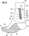
- a second embodiment of a leg garment with compression areas and stimulus induction zones is disclosed in U.S. Pat Fig. 14 and 15 shown.
- This leg garment is a sock 206 having a waist region 102 at the upper end of the sock 206, a shaft region 104 adjoining the waist region 102, and a foot region 106 adjoining the shaft region 104 downwardly and forwardly worn state encloses the foot of the wearer.
- the lower half of the foot region 106 of the sock 206 forms a sole region 108, which comprises a lower half of a heel region 112, a lower half of a toe region 116 and an intermediate region 118 located between the heel region 112 and the toe region 116.
- the shaft region 104 and the foot region 106 of the sock 206 are formed, preferably continuously, from a base knit 122 comprising one or more ground yarns and optionally one or more plating yarns.
- the ground yarn (s) and plating filament (s) may be formed of any material, such as a natural fiber or a manmade fiber.
- the sock 206 may be provided with one or more padding.
- the foot portion 106 of the sock 206 may be provided with a sole pad 208 disposed between the toe portion 116 and the heel portion 112.
- the sock 206 further includes one or more compression regions 142 in which the sock 206, when worn, exerts a compressive action on the leg of the wearer.
- This compression effect can be achieved in particular by the incorporation of one or more elastic threads into the basic knit 122 of the sock 206.
- the elastic thread (s) may in particular comprise elastane.
- the sock 206 may include a first compression portion 142a extending downwardly from the upper edge 144 of the shaft portion 104 to a lower edge 146 of the first compression portion 142a.
- the lower edge 146 of the first compression region 142a preferably lies below an ankle region 148 of the sock 206, which rests against the ankle of the wearer in the worn state of the sock 206.
- the sock 206 may have further compression regions, for example in the midfoot region.
- the toe area 116 receives comfort reasons preferably no compression effect.
- the compression strength in the compression region 142a is preferably at least about 7 mm Hg and / or at most about 25 mm Hg.
- the compression strength may be substantially constant in the compression region 142a or may also have a gradient.
- the compression region 142a may have a compression curve in which the compression strength decreases from the bottom to the top.
- the compression strength at the upper edge 144 of the compression region 142a is from about 60% to about 80% of the compression strength at the lower edge 146 of the compression region 142a.
- the stocking 206 includes one or more irritation induction zones 154, each provided with a stimulus-inducing structure 156.
- Each stimulus-inducing structure 156 comprises, as in the Fig. 1 to 3 illustrated first embodiment of a leg garment, functional elements 158, which cause a sensory irritation and a proprioreceptive stimulation of the musculature of the wearer in the worn state of the sock 206.
- the sock 206 in particular comprises two stimulus induction zones 154c and 154d, the stimulus-inducing structures 156 of which are arranged in the worn state of the sock 206 on the left or right of the Achilles tendon of the wearer.
- the stimulus induction zones 154c and 154d are thus disposed on opposite sides of an Achilles tendon region 210 of the sock.
- stimulus induction zones 154c and 154d and their stimulus-inducing structures 156 preferably extend behind the respective associated ankle region 148 and do not cover the respective associated ankle region 148.
- the functional elements 158 of the irritation-inducing structures 156 are disposed on the inside of the sock 206 so that they can act directly on the skin of the wearer.
- the functional elements 158 of the stimulus induction zones 154 therefore do not have to be visible from the outside of the sock 206 (as shown in FIGS Fig. 14 and 15 the case is).
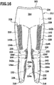
- One in the Fig. 16 and 17 illustrated third embodiment of a leg garment is different from that in the Fig. 1 to 3 illustrated first embodiment in that the leg garment is formed as leggings 212.
- leggings are in Fig. 16 from the front and in Fig. 17 shown from the left.
- the leggings 212 include a waistband region 102 at the top, a body portion 214 downwardly adjacent the waistband portion 102, and two leg portions 216 extending downwardly from the body portion 214, each extending to a respective lower waistband portion 218.
- Each leg portion 216 includes a thigh portion 220, a knee portion 222, and a lower leg portion 224.
- the leggings 212 further include one or more compression regions 142 in which the leggings 212, when worn, exert a compressive action on the body of the wearer.
- This compression effect can be achieved in particular by incorporating one or more elastic threads into the basic knit of the leggings 212.
- the elastic thread (s) may in particular comprise elastane.
- leggings 212 at each leg portion 216 may include a first compression portion 142a that extends downwardly from an upper edge 144 to an upper edge 228 of the respective lower collar 226.
- the upper edge 144 of the first compression region 142a is preferably below the knee region 222, which rests in the worn state of the leggings 212 at the knee of the wearer.
- each leggings 212 on each leg region 216 may include a second compression region 142b extending downwardly from an upper edge 228 of the respective leg region 216 to a lower edge 230 of the second compression region 142b, which is preferably above the respective knee region 222 of the leg region 216 runs.
- the lower edge 230 of the second compression portion 142b and the upper edge 144 of the first compression portion 142a are spaced from each other.
- the compression regions 142a, 142b directly adjoin one another and form a coherent compression region of the leggings 212.
- the compression strength in the first compression region 142a and / or in the second compression region 142b is preferably at least about 7 mm Hg and / or at most about 32 mm Hg.
- the compression strength may be constant in the first compression region 142a and / or in the second compression region 142b over the respective compression region 142a, 142b or may also have a gradient.
- first compression region 142a and / or the second compression region 142b may have a compression curve in which the compression strength decreases from bottom to top.
- the compression strength at the upper edge 144 of the first compression region 142a or at the upper edge 228th of the second compression portion 142b is from about 60% to about 80% of the compression strength at the lower edge 226 of the first compression portion 142a and at the lower edge 230 of the second compression portion 142b, respectively.
- leggings 212 include one or more stimulus induction zones 154, each provided with a stimulus-inducing structure 156.
- Each stimulus-inducing structure 156 comprises functional elements 158 which, in the worn state of the leggings 212, cause sensory irritation and proprioreceptive stimulation of the musculature of the wearer.
- These functional elements 158 may be constructed and manufactured in the same way as in the above-described first embodiment of a leg garment.
- the functional elements 158 are preferably arranged as elevations on the inside of the leggings 212, so that they can act directly on the skin of the wearer.
- the leggings 212 on the lower leg portions 224 of the leg portions 216 may include stimulus induction zones 154a that extend on the outside of the lower leg along the tibialis muscle / tendon ligament anteriorly and / or along the peroneus longus muscle / tendon ligament.
- leggings 212 in the lower leg portions 224 of the leg portions 226 may include irritation induction zones 154e that, in the worn state of the leg garment, overlap at least partially with the musculus gastrocnemius on the inner side of the lower leg.
- an outer contour 232 of the stimulus induction zone 154e substantially coincides with an outer contour of the Musculus gastrocnemius muscle.
- the leggings 212 in the knee region 222 of the leg regions 226 may have irritation induction zones 154f and 154g which, in the worn state of the leg garment, face on the inner side (facing the other leg of the wearer) or on the opposite side of the wearer ) are arranged outside of the patella of the wearer and are preferably formed substantially arcuate.
- Fig. 16 2 the arrangement of stimulus induction zones 154f on the inner side of the respective knee region 222 is shown.
- Fig. 17 For example, the arrangement of a stimulus induction zone 154g on the outer side of a knee region 222 is shown.
- the stimulus induction zones 154f and / or 154g in the worn state of the leg garment at least partially overlap with the muscle vastus medialis and / or with the muscle musculus vastus lateralis.
- an outer contour 232 of the stimulus induction zones 154f and / or 154g essentially corresponds to an outer contour of the Musculus vastus medialis muscle and / or an outer contour of the muscle Musculus vastus lateralis.
- leggings 212 on the front sides of the thigh regions 220 of the leg regions 216 may be provided with stimulus induction zones 154h which, in the worn state of the leg garment, overlap at least partially with the muscle musculus rectus femoris.
- an outer contour 232 of the stimulus induction zones 154h substantially corresponds to an outer contour of the Musculus rectus femoris muscle.
- the leggings 212 may further include stimulus induction zones 154i extending from a lower edge 234 of the waist 102 down over one side of the torso portion 214 and in the thigh portion 220 of the respective leg portion 216 on the outside of the thigh from hip to short extend above the stimulus induction zones 154g on the outside of the knee region 222.
- the positioning of the stimulus induction zones 154i preferably takes place in such a way that the stimulus induction zones 154i overlap, in particular essentially completely, with the muscle gluteus maxims muscle, the gluteus minimus muscle and / or the iliotibial fiber tract.
- leggings 212 on the back of the thigh regions 220 of the leg regions 216 may comprise further stimulus induction zones (not shown) which, when worn, cover the posterior flexor muscles, preferably substantially completely.
- Procroreceptive pacing results in improved synchronization of the muscles recruited for walking or running.
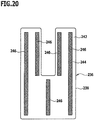
- At least one stimulus-inducing structure 156 may include at least one support member 236 (see FIG Fig. 18 ), on which a plurality of functional elements 158 are formed.
- the support element 236 with the functional elements 158 can be manufactured separately from the main body 170 of the legwear and then, releasably or permanently, be connected to the main body 170 of the leggown.
- an outer contour 238 of the carrier element 236 preferably corresponds substantially to the outer contour 232 of the associated stimulus induction zone 154.
- outer contour 238 is purely exemplary and can be replaced in particular by any other outer contour, which corresponds to the outer contour 232 of any Reizindumieszone 154.
- the carrier element 236 comprises a textile material, namely a knitted fabric.
- the support element 236 is arranged on the base body 170 of the leg garment such that the stimulus-inducing functional elements 158 lie on a front side 240 of the support element 236 facing away from the main body 170 of the leg garment and face the wearer's body in the worn state of the leg garment.
- the base body 170 of the leg garment facing back 242 of the support member 236 may be provided with fastening devices 244.
- the fastening devices 244 may be formed, for example, as adhesive elements 246 which cooperate with adhesive elements (not shown) on the main body 170 of the leg garment to releasably secure the carrier element 236 to the main body 170 of the leg garment.
- the adhesive elements 246 may form part of an adhesive closure or hook and loop fastener.
- a releasably secured to the base body 170 of the leggear piece support member 236 are the fastening devices 244 as locking elements 248th formed, which with (not shown) body-side locking elements can be latched to releasably fix the support member 236 to the base body 170 of the leg garment.
- At least one carrier element-side latching element 248 and a hereby cooperating main body-side latching element together form a push button.
- the functional elements 158 in the worn state of the leg garment do not directly contact the skin of the wearer of the leg garment, but in the worn state of the leg garment, a cover 250 between the functional elements 158 and 15 the body of the wearer is arranged.
- the cover 250 may be formed, for example, from a textile material or from a film, in particular from a plastic material.
- An outer contour 252 of the cover 250 preferably corresponds substantially to the outer contour 232 of the respective stimulus induction zone 154.
- the cover 250 for example by means of a seam 254, with a separately produced from the base body 170 back wall 256, for example, a textile material or a film, in particular made of a plastic material, and so together with the rear wall 256 a Form pocket 258, in which the functional elements 158 of the stimulus-inducing structure 156 are added.
- the pocket 258 is assembled separately from the base 170 of the cover 250 and the back wall 256 before the pocket 258 is secured as a whole, permanently or detachably, to the base 170 of the leg garment.
- the pocket 258 may be closed along its outer contour or have an opening through which the functional elements 158 and in particular the functional elements 158 carrying support members 236 are inserted into the pocket 258.
- all functional elements 158 of the stimulus-inducing structure 156 are arranged on a single carrier element 236.
- the stimulus-inducing structure 156 has a plurality of support elements 236, which in turn each carry a plurality of stimulus-inducing functional elements 158.
- the support members 236 may be manufactured separately from the cover 250 and separately from the back wall 256 and subsequently connected to the back wall 256 and / or to the cover 250, for example by gluing, welding and / or sewing.
- the cover 250 of the opposite rear side of the pocket 258 is not formed by a separately formed from the base body 170 rear wall 256, but by a portion 260 of the base body 170.
- a (not shown) biasing element is arranged in the pocket 258, which in the worn state of the leg garment, the functional elements 158 to the body of the wearer out biased so as to increase the contact pressure of the functional elements 158 on the skin of the wearer through the cover 250 therethrough.
- a biasing element may comprise, for example, a foam insert.
- the use of such a biasing element may be particularly useful when the body of the wearer of the leg garment in the region in which the relevant stimulus induction zone 154 is arranged concave.
- the use of a cover 250 between the functional elements 158 and the body of the wearer of the leg garment is particularly advantageous when the functional elements 158 are comparatively hard, comparatively high and / or comparatively pointed.
Landscapes
- Engineering & Computer Science (AREA)
- Textile Engineering (AREA)
- Health & Medical Sciences (AREA)
- General Health & Medical Sciences (AREA)
- Physical Education & Sports Medicine (AREA)
- Professional, Industrial, Or Sporting Protective Garments (AREA)
- Socks And Pantyhose (AREA)
- Outer Garments And Coats (AREA)
- Carbon And Carbon Compounds (AREA)
- Orthopedics, Nursing, And Contraception (AREA)
- Crystals, And After-Treatments Of Crystals (AREA)
Priority Applications (4)
| Application Number | Priority Date | Filing Date | Title |
|---|---|---|---|
| PL17175094T PL3248490T3 (pl) | 2012-09-12 | 2013-09-12 | Artykuł odzieżowy na nogi |
| SI201331465T SI3248490T1 (sl) | 2012-09-12 | 2013-09-12 | Oblačilo za noge |
| RS20190797A RS58987B1 (sr) | 2012-09-12 | 2013-09-12 | Odevni predmet za noge |
| HRP20191155TT HRP20191155T1 (hr) | 2012-09-12 | 2019-06-26 | Odjevni predmet za noge |
Applications Claiming Priority (3)
| Application Number | Priority Date | Filing Date | Title |
|---|---|---|---|
| DE102012216180.5A DE102012216180B4 (de) | 2012-09-12 | 2012-09-12 | Beinbekleidungsstück |
| EP13762119.9A EP2895020B2 (de) | 2012-09-12 | 2013-09-12 | Beinbekleidungsstück |
| PCT/EP2013/068914 WO2014041075A1 (de) | 2012-09-12 | 2013-09-12 | Beinbekleidungsstück |
Related Parent Applications (2)
| Application Number | Title | Priority Date | Filing Date |
|---|---|---|---|
| EP13762119.9A Division-Into EP2895020B2 (de) | 2012-09-12 | 2013-09-12 | Beinbekleidungsstück |
| EP13762119.9A Division EP2895020B2 (de) | 2012-09-12 | 2013-09-12 | Beinbekleidungsstück |
Publications (2)
| Publication Number | Publication Date |
|---|---|
| EP3248490A1 EP3248490A1 (de) | 2017-11-29 |
| EP3248490B1 true EP3248490B1 (de) | 2019-03-27 |
Family
ID=49165747
Family Applications (4)
| Application Number | Title | Priority Date | Filing Date |
|---|---|---|---|
| EP17175094.6A Active EP3248490B1 (de) | 2012-09-12 | 2013-09-12 | Beinbekleidungsstück |
| EP13762120.7A Active EP2895021B2 (de) | 2012-09-12 | 2013-09-12 | Oberkörperbekleidungsstück |
| EP13762119.9A Active EP2895020B2 (de) | 2012-09-12 | 2013-09-12 | Beinbekleidungsstück |
| EP17175200.9A Active EP3243396B1 (de) | 2012-09-12 | 2013-09-12 | Oberkörperbekleidungsstück |
Family Applications After (3)
| Application Number | Title | Priority Date | Filing Date |
|---|---|---|---|
| EP13762120.7A Active EP2895021B2 (de) | 2012-09-12 | 2013-09-12 | Oberkörperbekleidungsstück |
| EP13762119.9A Active EP2895020B2 (de) | 2012-09-12 | 2013-09-12 | Beinbekleidungsstück |
| EP17175200.9A Active EP3243396B1 (de) | 2012-09-12 | 2013-09-12 | Oberkörperbekleidungsstück |
Country Status (15)
| Country | Link |
|---|---|
| US (4) | US10779586B2 (pl) |
| EP (4) | EP3248490B1 (pl) |
| CN (6) | CN109567284A (pl) |
| DE (1) | DE102012216180B4 (pl) |
| DK (2) | DK3243396T3 (pl) |
| ES (2) | ES2733080T3 (pl) |
| HK (1) | HK1206210A1 (pl) |
| HR (2) | HRP20191156T1 (pl) |
| HU (2) | HUE043936T2 (pl) |
| PL (2) | PL3243396T3 (pl) |
| PT (2) | PT3248490T (pl) |
| RS (2) | RS58970B1 (pl) |
| SI (2) | SI3248490T1 (pl) |
| TR (2) | TR201905904T4 (pl) |
| WO (2) | WO2014041077A1 (pl) |
Families Citing this family (35)
| Publication number | Priority date | Publication date | Assignee | Title |
|---|---|---|---|---|
| DE102012216180B4 (de) | 2012-09-12 | 2026-05-07 | Falke Kgaa | Beinbekleidungsstück |
| DE102014103309A1 (de) * | 2014-03-12 | 2015-09-17 | Falke Kgaa | Verfahren zum Herstellen eines Bekleidungsstücks und Bekleidungsstück |
| US20150264995A1 (en) * | 2014-03-24 | 2015-09-24 | Henry Lucius Hilderbrand, IV | Grip-Enhancing Sportswear and Methods of Manufacturing the Same |
| DE102014110623A1 (de) * | 2014-07-28 | 2016-01-28 | Hexonia Gmbh | Textiles Bekleidungsstück mit einer ballistischen Schutzausrüstung |
| DE102014111939A1 (de) * | 2014-08-21 | 2016-02-25 | Ntt New Textile Technologies Gmbh | Verfahren zur Herstellung eines Bekleidungsstücks |
| USD764750S1 (en) * | 2015-01-21 | 2016-08-30 | Nicholas Ballesteros | Set of shirt sleeves |
| HRP20210401T1 (hr) | 2015-03-27 | 2021-04-16 | Trerè Innovation S.r.l. | Odjeća sa elastičnim umetcima proizvedena pomoću kružnih strojeva |
| CN111493381B (zh) | 2015-05-22 | 2022-06-03 | 耐克创新有限合伙公司 | 具有预配置压缩区段和一体式结构图案的训练紧身衣 |
| US20170035120A1 (en) * | 2015-08-03 | 2017-02-09 | Tbl Licensing Llc | Sock with selective yarn placement |
| DE102015119657A1 (de) * | 2015-11-13 | 2017-05-18 | Falke Kgaa | Bekleidungsstück |
| DE102015119654A1 (de) * | 2015-11-13 | 2017-05-18 | Falke Kgaa | Bekleidungsstück |
| CN106345113A (zh) * | 2016-11-04 | 2017-01-25 | 浙江华尔纺织科技有限公司 | 腿套 |
| USD849390S1 (en) * | 2017-03-14 | 2019-05-28 | Sultan Abdul-Malik | Compression sock |
| DE202018006115U1 (de) | 2017-03-29 | 2019-04-05 | Fxf Gmbh | Mit oberflächennahen Nerven wechselwirkende Fuß- und/oder Knöchelbandage |
| US10743805B2 (en) | 2017-06-02 | 2020-08-18 | International Business Machines Corporation | Haptic interface for generating preflex stimulation |
| EP3644910B1 (en) * | 2017-06-27 | 2021-08-25 | Peúgas Carlos Maia, Lda | Sock for preventing ankle injury |
| EP3687326A4 (en) * | 2017-09-26 | 2021-07-07 | Fortiac Corporation | NON-STRETCH GARMENT WITH KNITTED STRETCH PANELS |
| KR102863224B1 (ko) * | 2017-12-12 | 2025-09-29 | 트레레 이노베이션 에스.알.엘. | 양말에 대한 동적 환기 시스템 |
| USD840669S1 (en) * | 2017-12-29 | 2019-02-19 | Jockey International, Inc. | Sock |
| WO2019191498A1 (en) * | 2018-03-28 | 2019-10-03 | Kuhner Stout Emeline | Energizing garment |
| EP3575463B1 (de) * | 2018-06-01 | 2023-04-05 | medi GmbH & Co. KG | Beinbekleidungsstück, insbesondere strumpf |
| WO2019238240A1 (en) * | 2018-06-15 | 2019-12-19 | Puma SE | Sports garment for team sports |
| US11819064B2 (en) | 2018-11-30 | 2023-11-21 | Nike, Inc. | Upper torso garment with varied tuck binder knit structure |
| DE102018132640B4 (de) | 2018-12-18 | 2026-04-30 | Ottobock Se & Co. Kgaa | Elastisches Flächenmaterial, Bandage daraus und Verfahren zu dessen Herstellung |
| PT3733941T (pt) * | 2019-05-03 | 2023-01-19 | Medi Gmbh & Co Kg | Peça tricotada de compressão com efeito de aderência |
| FR3103103A1 (fr) * | 2019-11-18 | 2021-05-21 | Thuasne | Vetement de compression et/ou de contention pour le traitement du lymphoedeme |
| DE202020102580U1 (de) | 2020-05-07 | 2021-08-11 | Julius Zorn Gmbh | Kompressionsgestrick und Kompressionsartikel, insbesondere zur Gewebe-, Nerven-, Muskel- und Faszienstimulation |
| DE102020112429A1 (de) | 2020-05-07 | 2021-11-11 | Julius Zorn Gmbh | Kompressionsgestrick und Kompressionsartikel, insbesondere zur Gewebe-, Nerven-, Muskel- und Faszienstimulation |
| IT202000010843A1 (it) * | 2020-05-13 | 2021-11-13 | Coffinardi & Delpanno Ind Srl | Calza con efficacia funzionale biomeccanica, circolatoria e neurologica |
| IT202000032024A1 (it) * | 2020-12-23 | 2022-06-23 | Coffinardi & Delpanno Ind Srl | Calza o simili comprendente una struttura di calza con effetti biomeccanici particolarmente adatta per calcio, ciclismo e sport similari |
| USD928458S1 (en) * | 2021-02-03 | 2021-08-24 | Xiamen Wenmi Technology Co., Ltd. | Long sleeve shirt |
| CN117702351A (zh) * | 2022-09-08 | 2024-03-15 | 香港纺织及成衣研发中心 | 压缩服饰的定制方法、装置、电子设备和可读存储介质 |
| JP7488598B2 (ja) * | 2022-09-28 | 2024-05-22 | 株式会社Aband | 靴下 |
| WO2024168020A1 (en) * | 2023-02-07 | 2024-08-15 | Qolify Llc | Compression garments and methods of manufacture |
| CN118716715A (zh) * | 2024-06-17 | 2024-10-01 | 苏州闰博尔纺织科技有限公司 | 一种四针床编织的全成形滑雪压缩服及其编织方法 |
Family Cites Families (89)
| Publication number | Priority date | Publication date | Assignee | Title |
|---|---|---|---|---|
| AT11230B (de) | 1901-06-26 | 1903-03-26 | Nikolaus Dobrzanski | Selbsttätige, seitlich lösbare Eisenbahnwagenkupplung. |
| AT193541B (de) | 1955-11-18 | 1957-11-25 | Elsa Hammerer Fa | Medizinischer Krampfaderstrumpf |
| US3013420A (en) † | 1957-12-03 | 1961-12-19 | Cormier Hosiery Mills Inc | Elastic fabric for a stocking top |
| DE1842303U (de) | 1961-05-19 | 1961-11-30 | Strumpf Fabriken A Marum Wwe G | Laufsohle fuer struempfe oder socken. |
| US3159990A (en) | 1961-10-18 | 1964-12-08 | Stretch Corp U | Elastic bobby sock top |
| US3216223A (en) | 1963-07-16 | 1965-11-09 | High Point Seamless Hosiery Mi | Stocking and method of making the same |
| FR2115802A5 (en) | 1970-11-25 | 1972-07-07 | Tornhajm Gilbert | Close-fitting garments - from knitted ribbed constructions |
| US3854978A (en) * | 1972-11-24 | 1974-12-17 | Johnson & Johnson | Method for manufacturing a non-slip waistband product |
| DE2547809A1 (de) * | 1975-10-25 | 1977-04-28 | Schmidt & Co Karl J G | Strumpfartiger fussknoechelschuetzer fuer sportler |
| US4195497A (en) * | 1977-06-29 | 1980-04-01 | Allstate Hosiery Sales, Inc. | Aerated stocking |
| JPS54125789A (en) | 1978-03-15 | 1979-09-29 | Toray Industries | Composite knitted fabric |
| US4237707A (en) | 1978-09-07 | 1980-12-09 | Kayser-Roth Hoisery, Inc. | Dress weight tube sock with mock rib leg and method of knitting |
| US4216547A (en) | 1979-02-02 | 1980-08-12 | Picchione P Vincent | Injury protection device for athletes |
| US4372998A (en) | 1980-08-26 | 1983-02-08 | Shimada Shoji Co., Ltd. | Heat adhesive tapes for finishing hems of trousers, skirts and like articles |
| US7252929B2 (en) | 1989-02-09 | 2007-08-07 | United States Of America, As Represented By The Secretary, Dept Of Health & Human Services | Methods for identifying alpha PDGFR agonists and antagonists |
| JP2603769B2 (ja) * | 1991-05-22 | 1997-04-23 | 株式会社 ワコール | 人体の体表面に圧接して着用されるテーピング機能を有する下腿部用サポーター |
| DE4216650A1 (de) | 1992-01-29 | 1993-08-05 | Rudolf Weyergans | Kosmetischer kompressionsstrumpf |
| DE4202421A1 (de) | 1992-01-29 | 1993-08-05 | Bosch Gmbh Robert | Vorrichtung zum wischen von scheiben an kraftfahrzeugen |
| US5329640A (en) | 1993-04-14 | 1994-07-19 | Hourigan James T | Cushioned sock |
| US5791164A (en) * | 1996-06-17 | 1998-08-11 | Milliken Research Corporation | Outdoor sporting fabric |
| US5857947A (en) * | 1997-07-14 | 1999-01-12 | Dicker; Timothy P. | Energy expenditure/training garment |
| IT1295328B1 (it) | 1997-10-14 | 1999-05-04 | Calzificio Pinelli Srl | Corpino di calza-maglia,sostanzialmente la parte costituente la mutanda,realizzato da una maglia a punto trattenuto tale da conferire |
| FR2770399B3 (fr) * | 1997-11-03 | 1999-12-03 | Jean Patrick Errera | Chaussettes, bas et collants massants |
| DE29800791U1 (de) | 1998-01-20 | 1999-05-20 | Franz Falke-Rohen Strumpffabriken Zweigniederlassung der Franz Falke-Rohen, 57392 Schmallenberg | Socke mit asymmetrischer Spitze |
| IT1301706B1 (it) | 1998-06-12 | 2000-07-07 | Csp Internat Ind Calze S P A | Calza, particolarmente del tipo collant, ad effetto modellante, pergambe snelle e diritte. |
| IT244098Y1 (it) * | 1998-06-26 | 2002-03-07 | Vegas Spa | Struttura di calza ad elevato conforto |
| FR2796967A1 (fr) | 1999-07-29 | 2001-02-02 | Breilly Sa | Chaussette tricotee a effet relaxant |
| DE19940018A1 (de) | 1999-08-24 | 2001-03-01 | Beiersdorf Ag | Strumpf mit einer nahtfrei angebrachten rutschhemmenden Beschichtung im Randbereich der oberen Öffnung |
| DE19946019C2 (de) | 1999-09-25 | 2003-08-28 | Bauerfeind Orthopaedie Gmbh & | Kompressionsmanschette zur Behandlung von Beinleiden |
| GB9929867D0 (en) * | 1999-12-17 | 2000-02-09 | Speedo International Limited | Articles of clothing |
| EP1241286B1 (en) | 2001-03-05 | 2003-05-02 | Karin Co., Ltd | Underwear |
| US6378138B1 (en) | 2001-04-19 | 2002-04-30 | Ridgley Aleta O'dell | Heavenly hosiery |
| US6892396B2 (en) * | 2002-05-23 | 2005-05-17 | Mizuno Corporation | Undershirt |
| US7730552B2 (en) * | 2003-04-15 | 2010-06-08 | Wacoal Corp. | Pants garment |
| JP2007509253A (ja) * | 2003-10-23 | 2007-04-12 | サラ リー コーポレーション | シームレスニット衣服 |
| DE102004006485A1 (de) | 2004-02-10 | 2005-08-25 | Adidas International Marketing B.V. | Bekleidungsstück |
| US7434423B1 (en) | 2004-04-30 | 2008-10-14 | Carolon Company | Impact protection and performance garment |
| WO2006002371A2 (en) * | 2004-06-24 | 2006-01-05 | Malden Mills Industries, Inc. | Engineered fabric articles |
| US7007517B2 (en) * | 2004-08-02 | 2006-03-07 | Menzies—Southern Hosiery Mills, Inc. | Knit sock |
| US7346936B2 (en) * | 2004-08-09 | 2008-03-25 | Vargas Stacey L | Pilates sock with tactile posture feedback |
| WO2006032096A1 (en) | 2004-09-23 | 2006-03-30 | Skins Compression Garments Pty Limited | Compression garments and a method of manufacture |
| US7669250B2 (en) * | 2004-10-14 | 2010-03-02 | Nike, Inc. | Article of apparel incorporating an embossed material |
| JP2006144210A (ja) * | 2004-10-19 | 2006-06-08 | Onyone Kk | スポーツウェア |
| WO2006069308A1 (en) | 2004-12-21 | 2006-06-29 | Smart Fitness Products Llc | Garment with enhanced knee support |
| FR2879900B1 (fr) | 2004-12-24 | 2007-10-12 | Promiles Sa | Collant a effet localise de contention pour la pratique d'un sport |
| CN101564204B (zh) * | 2005-04-01 | 2010-12-08 | 郡是株式会社 | 能够自由裁剪的服装 |
| US7533423B2 (en) * | 2005-04-15 | 2009-05-19 | Fun In The Saddle, Inc. | Equestrian riding breeches garment and method for its manufacture |
| US20060260024A1 (en) | 2005-05-18 | 2006-11-23 | Seung-Hee Lee | Sock having part for preventing slipping-down phenomenon of sock |
| US7636950B2 (en) | 2005-09-30 | 2009-12-29 | Nike, Inc. | Article of apparel with zonal stretch resistance |
| JP4673182B2 (ja) * | 2005-10-18 | 2011-04-20 | アサヒマカム株式会社 | 衣類 |
| FR2902608B1 (fr) * | 2006-06-22 | 2008-10-24 | Dbapparel Operations Soc Par A | Article tricote chaussant,notamment mi-bas relaxants |
| WO2008061942A2 (de) * | 2006-11-23 | 2008-05-29 | Basf Se | Verfahren zur herstellung von fasern |
| US7861318B2 (en) | 2007-01-29 | 2011-01-04 | Morning Pride Manufacturing, L.L.C. | Pad wearable over articulated joint |
| FR2915851B1 (fr) * | 2007-05-11 | 2009-08-21 | Promiles Snc | Article d'habillement a effet de contention heterogene pour la pratique d'un sport |
| US10849779B2 (en) | 2007-05-23 | 2020-12-01 | Timothy W. Brown | Posture improvement devices and methods for use |
| US9119707B2 (en) | 2007-05-23 | 2015-09-01 | Intelliskin Usa, Llc | Sensory motor stimulation garment and method |
| US9125442B2 (en) * | 2007-05-23 | 2015-09-08 | Intelliskin Usa, Llc | Sensory motor stimulation garment and method |
| US7934267B2 (en) * | 2007-05-31 | 2011-05-03 | Nike, Inc. | Articles of apparel providing enhanced body position feedback |
| US7996924B2 (en) * | 2007-05-31 | 2011-08-16 | Nike, Inc. | Articles of apparel providing enhanced body position feedback |
| US8336118B2 (en) * | 2007-05-31 | 2012-12-25 | Nike, Inc. | Articles of apparel providing enhanced body position feedback |
| JP5414998B2 (ja) * | 2007-08-21 | 2014-02-12 | 日清紡ホールディングス株式会社 | 接着テープ |
| JP5102611B2 (ja) * | 2007-12-27 | 2012-12-19 | 岡本株式会社 | 靴下 |
| JP2009167552A (ja) * | 2008-01-15 | 2009-07-30 | Tokai Thermo Kk | 衣料用芯地布帛及び衣料 |
| DE202008005533U1 (de) | 2008-04-21 | 2009-07-09 | Medi Gmbh & Co. Kg | Orthopädisches Hilfsmittel mit Wirkeinlage |
| DE202008006066U1 (de) | 2008-05-02 | 2009-09-17 | Julius Zorn Gmbh | Rundgestrick für die Kompressionstherapie von Lymphödemen |
| US20100050699A1 (en) * | 2008-06-06 | 2010-03-04 | Nathaniel H. Kolmes | Lightweight, cut and/or abrasion resistant garments, and related protective wear |
| CN201219516Y (zh) * | 2008-06-19 | 2009-04-15 | 赖志佳 | 绑带 |
| US7867185B2 (en) * | 2008-07-01 | 2011-01-11 | Circaid Medical Products | Graduated compression device for the treatment of circulatory disorders |
| US20100050313A1 (en) * | 2008-08-26 | 2010-03-04 | Shackelford Jr John P | Posture improving device |
| US20100056973A1 (en) * | 2008-08-28 | 2010-03-04 | Farrow Medical Innovations, Inc. | Therapeutic Compression Garments |
| US8172782B2 (en) * | 2008-11-25 | 2012-05-08 | Mmi-Ipco, Llc | Compression garments |
| CN201459349U (zh) * | 2009-08-07 | 2010-05-12 | 东莞润达弹性织造有限公司 | 一种氨纶针织织带 |
| JP5394875B2 (ja) * | 2009-09-30 | 2014-01-22 | 日清紡テキスタイル株式会社 | 織編物 |
| US20110083246A1 (en) * | 2009-10-14 | 2011-04-14 | Ranil Kirthi Vitarana | Garment with Elastomeric Coating |
| DE102009050031B3 (de) | 2009-10-21 | 2011-03-03 | Hermann Christiansen | Material für ein Produkt zur Kompression von Körperteilen sowie ein medizinischer Verband und ein Kleidungsstück aus diesem Material |
| WO2011059937A2 (en) * | 2009-11-12 | 2011-05-19 | Saucony, Inc. | Training and recovery clothing and related methods |
| CN101766334B (zh) * | 2009-12-24 | 2011-06-22 | 平湖市金象纺织品有限公司 | 沙滩袜 |
| AT11230U3 (de) | 2010-01-20 | 2011-01-15 | Ines Mueller | Kleidung |
| FR2961065B1 (fr) * | 2010-06-14 | 2013-04-26 | Salomon Sas | Vetement de sport ajuste |
| JP2012052276A (ja) * | 2010-09-03 | 2012-03-15 | Rushian:Kk | インナーウェア |
| CN202085728U (zh) * | 2010-12-25 | 2011-12-28 | 陆思烨 | 一种保健内裤 |
| BR112013021576A2 (pt) | 2011-02-25 | 2016-11-16 | Amarcod Ind Abbigliamento S R L | peça de vestuário para a assistência neuro-muscular-esquelética |
| CN102166047A (zh) * | 2011-03-09 | 2011-08-31 | 山东如意科技集团有限公司 | 防辐射西装平服夹衬的热熔线工艺 |
| CN201929003U (zh) * | 2011-03-21 | 2011-08-17 | 简秋雪 | 强化提臀收腹连体衣 |
| CN202143449U (zh) * | 2011-06-23 | 2012-02-15 | 深圳市美百年服装有限公司 | 矫姿保健内衣 |
| US20140230124A1 (en) | 2011-10-11 | 2014-08-21 | Puma SE | Article of clothing |
| DE202012007243U1 (de) * | 2012-07-27 | 2012-08-23 | Christian Mertens | Bekleidungseinheit |
| DE102012216180B4 (de) | 2012-09-12 | 2026-05-07 | Falke Kgaa | Beinbekleidungsstück |
| US10426657B2 (en) * | 2014-10-03 | 2019-10-01 | Rachel's Remedies, LLC | Thermal device for treating breastfeeding conditions |
-
2012
- 2012-09-12 DE DE102012216180.5A patent/DE102012216180B4/de active Active
-
2013
- 2013-09-12 TR TR2019/05904T patent/TR201905904T4/tr unknown
- 2013-09-12 HU HUE17175094A patent/HUE043936T2/hu unknown
- 2013-09-12 CN CN201811019637.XA patent/CN109567284A/zh active Pending
- 2013-09-12 CN CN201380047479.8A patent/CN104619203A/zh active Pending
- 2013-09-12 PL PL17175200T patent/PL3243396T3/pl unknown
- 2013-09-12 SI SI201331465T patent/SI3248490T1/sl unknown
- 2013-09-12 EP EP17175094.6A patent/EP3248490B1/de active Active
- 2013-09-12 PL PL17175094T patent/PL3248490T3/pl unknown
- 2013-09-12 CN CN201810756316.1A patent/CN108813750B/zh not_active Expired - Fee Related
- 2013-09-12 RS RS20190798A patent/RS58970B1/sr unknown
- 2013-09-12 CN CN201380047524.XA patent/CN104619205B/zh active Active
- 2013-09-12 HK HK15107097.0A patent/HK1206210A1/xx unknown
- 2013-09-12 ES ES17175094T patent/ES2733080T3/es active Active
- 2013-09-12 DK DK17175200.9T patent/DK3243396T3/da active
- 2013-09-12 RS RS20190797A patent/RS58987B1/sr unknown
- 2013-09-12 SI SI201331466T patent/SI3243396T1/sl unknown
- 2013-09-12 DK DK17175094.6T patent/DK3248490T3/da active
- 2013-09-12 WO PCT/EP2013/068916 patent/WO2014041077A1/de not_active Ceased
- 2013-09-12 CN CN201810755934.4A patent/CN108936862A/zh active Pending
- 2013-09-12 WO PCT/EP2013/068914 patent/WO2014041075A1/de not_active Ceased
- 2013-09-12 PT PT17175094T patent/PT3248490T/pt unknown
- 2013-09-12 ES ES17175200T patent/ES2733121T3/es active Active
- 2013-09-12 HU HUE17175200A patent/HUE043931T2/hu unknown
- 2013-09-12 TR TR2019/05356T patent/TR201905356T4/tr unknown
- 2013-09-12 EP EP13762120.7A patent/EP2895021B2/de active Active
- 2013-09-12 PT PT17175200T patent/PT3243396T/pt unknown
- 2013-09-12 CN CN201811018930.4A patent/CN109222267B/zh not_active Expired - Fee Related
- 2013-09-12 EP EP13762119.9A patent/EP2895020B2/de active Active
- 2013-09-12 EP EP17175200.9A patent/EP3243396B1/de active Active
-
2015
- 2015-03-06 US US14/641,195 patent/US10779586B2/en active Active
- 2015-03-06 US US14/641,215 patent/US10905174B2/en active Active
-
2019
- 2019-06-26 HR HRP20191156TT patent/HRP20191156T1/hr unknown
- 2019-06-26 HR HRP20191155TT patent/HRP20191155T1/hr unknown
-
2020
- 2020-07-21 US US16/935,053 patent/US11684093B2/en active Active
- 2020-12-28 US US17/135,334 patent/US12053035B2/en active Active
Non-Patent Citations (1)
| Title |
|---|
| None * |
Also Published As
Similar Documents
| Publication | Publication Date | Title |
|---|---|---|
| EP2895020B1 (de) | Beinbekleidungsstück | |
| DE102017223737B4 (de) | Verfahren zur Herstellung eines Schuhoberteils | |
| DE102014220087B4 (de) | Flachgestricktes Schuhoberteil für Sportschuhe | |
| DE102013207156B4 (de) | Schuh, insbesondere ein Sportschuh | |
| DE102016222480A1 (de) | Bekleidungsstück, das Spinnenseide aufweist oder Schuh, der Spinnenseide aufweist | |
| DE102017223750B4 (de) | Gestrickte oder gewirkte Komponente | |
| DE102013101199B4 (de) | Kleidungsstück für den Oberkörper | |
| EP1538246A1 (de) | Beinbekleidungsstück | |
| EP1537793B1 (de) | Beinbekleidungsstück | |
| EP1538247B1 (de) | Beinbekleidungsstück | |
| DE20318854U1 (de) | Beinbekleidungsstück | |
| EP1537792B1 (de) | Beinbekleidungsstück | |
| DE20318851U1 (de) | Beinbekleidungsstück | |
| EP2953490A1 (de) | Kleidungsstück mit nahtlosen übergängen | |
| HK1256919B (en) | Leg covering item | |
| DE20318853U1 (de) | Beinbekleidungsstück | |
| HK1260750A1 (en) | Upper body covering item | |
| DE20318852U1 (de) | Beinbekleidungsstück |
Legal Events
| Date | Code | Title | Description |
|---|---|---|---|
| PUAI | Public reference made under article 153(3) epc to a published international application that has entered the european phase |
Free format text: ORIGINAL CODE: 0009012 |
|
| STAA | Information on the status of an ep patent application or granted ep patent |
Free format text: STATUS: THE APPLICATION HAS BEEN PUBLISHED |
|
| AC | Divisional application: reference to earlier application |
Ref document number: 2895020 Country of ref document: EP Kind code of ref document: P |
|
| AK | Designated contracting states |
Kind code of ref document: A1 Designated state(s): AL AT BE BG CH CY CZ DE DK EE ES FI FR GB GR HR HU IE IS IT LI LT LU LV MC MK MT NL NO PL PT RO RS SE SI SK SM TR |
|
| STAA | Information on the status of an ep patent application or granted ep patent |
Free format text: STATUS: REQUEST FOR EXAMINATION WAS MADE |
|
| 17P | Request for examination filed |
Effective date: 20180524 |
|
| RBV | Designated contracting states (corrected) |
Designated state(s): AL AT BE BG CH CY CZ DE DK EE ES FI FR GB GR HR HU IE IS IT LI LT LU LV MC MK MT NL NO PL PT RO RS SE SI SK SM TR |
|
| GRAP | Despatch of communication of intention to grant a patent |
Free format text: ORIGINAL CODE: EPIDOSNIGR1 |
|
| STAA | Information on the status of an ep patent application or granted ep patent |
Free format text: STATUS: GRANT OF PATENT IS INTENDED |
|
| INTG | Intention to grant announced |
Effective date: 20181008 |
|
| GRAS | Grant fee paid |
Free format text: ORIGINAL CODE: EPIDOSNIGR3 |
|
| GRAA | (expected) grant |
Free format text: ORIGINAL CODE: 0009210 |
|
| STAA | Information on the status of an ep patent application or granted ep patent |
Free format text: STATUS: THE PATENT HAS BEEN GRANTED |
|
| AC | Divisional application: reference to earlier application |
Ref document number: 2895020 Country of ref document: EP Kind code of ref document: P |
|
| AK | Designated contracting states |
Kind code of ref document: B1 Designated state(s): AL AT BE BG CH CY CZ DE DK EE ES FI FR GB GR HR HU IE IS IT LI LT LU LV MC MK MT NL NO PL PT RO RS SE SI SK SM TR |
|
| REG | Reference to a national code |
Ref country code: GB Ref legal event code: FG4D Free format text: NOT ENGLISH |
|
| REG | Reference to a national code |
Ref country code: CH Ref legal event code: EP |
|
| REG | Reference to a national code |
Ref country code: AT Ref legal event code: REF Ref document number: 1111936 Country of ref document: AT Kind code of ref document: T Effective date: 20190415 |
|
| REG | Reference to a national code |
Ref country code: IE Ref legal event code: FG4D Free format text: LANGUAGE OF EP DOCUMENT: GERMAN |
|
| REG | Reference to a national code |
Ref country code: DE Ref legal event code: R096 Ref document number: 502013012514 Country of ref document: DE |
|
| REG | Reference to a national code |
Ref country code: DK Ref legal event code: T3 Effective date: 20190522 |
|
| REG | Reference to a national code |
Ref country code: CH Ref legal event code: NV Representative=s name: ISLER AND PEDRAZZINI AG, CH |
|
| REG | Reference to a national code |
Ref country code: NL Ref legal event code: FP |
|
| REG | Reference to a national code |
Ref country code: HR Ref legal event code: TUEP Ref document number: P20191155 Country of ref document: HR |
|
| REG | Reference to a national code |
Ref country code: PT Ref legal event code: SC4A Ref document number: 3248490 Country of ref document: PT Date of ref document: 20190627 Kind code of ref document: T Free format text: AVAILABILITY OF NATIONAL TRANSLATION Effective date: 20190619 |
|
| REG | Reference to a national code |
Ref country code: SE Ref legal event code: TRGR |
|
| PG25 | Lapsed in a contracting state [announced via postgrant information from national office to epo] |
Ref country code: LT Free format text: LAPSE BECAUSE OF FAILURE TO SUBMIT A TRANSLATION OF THE DESCRIPTION OR TO PAY THE FEE WITHIN THE PRESCRIBED TIME-LIMIT Effective date: 20190327 |
|
| REG | Reference to a national code |
Ref country code: SK Ref legal event code: T3 Ref document number: E 30988 Country of ref document: SK |
|
| REG | Reference to a national code |
Ref country code: NO Ref legal event code: T2 Effective date: 20190327 |
|
| REG | Reference to a national code |
Ref country code: GR Ref legal event code: EP Ref document number: 20190401738 Country of ref document: GR Effective date: 20190906 |
|
| REG | Reference to a national code |
Ref country code: HU Ref legal event code: AG4A Ref document number: E043936 Country of ref document: HU |
|
| REG | Reference to a national code |
Ref country code: HR Ref legal event code: ODRP Ref document number: P20191155 Country of ref document: HR Payment date: 20190911 Year of fee payment: 7 Ref country code: HR Ref legal event code: T1PR Ref document number: P20191155 Country of ref document: HR |
|
| PG25 | Lapsed in a contracting state [announced via postgrant information from national office to epo] |
Ref country code: AL Free format text: LAPSE BECAUSE OF FAILURE TO SUBMIT A TRANSLATION OF THE DESCRIPTION OR TO PAY THE FEE WITHIN THE PRESCRIBED TIME-LIMIT Effective date: 20190327 Ref country code: RO Free format text: LAPSE BECAUSE OF FAILURE TO SUBMIT A TRANSLATION OF THE DESCRIPTION OR TO PAY THE FEE WITHIN THE PRESCRIBED TIME-LIMIT Effective date: 20190327 Ref country code: EE Free format text: LAPSE BECAUSE OF FAILURE TO SUBMIT A TRANSLATION OF THE DESCRIPTION OR TO PAY THE FEE WITHIN THE PRESCRIBED TIME-LIMIT Effective date: 20190327 |
|
| PGFP | Annual fee paid to national office [announced via postgrant information from national office to epo] |
Ref country code: CZ Payment date: 20190910 Year of fee payment: 7 Ref country code: LU Payment date: 20190924 Year of fee payment: 7 Ref country code: FI Payment date: 20190924 Year of fee payment: 7 Ref country code: SE Payment date: 20190926 Year of fee payment: 7 Ref country code: MC Payment date: 20190926 Year of fee payment: 7 Ref country code: DK Payment date: 20190925 Year of fee payment: 7 Ref country code: IE Payment date: 20190923 Year of fee payment: 7 Ref country code: NO Payment date: 20190925 Year of fee payment: 7 Ref country code: SK Payment date: 20190910 Year of fee payment: 7 Ref country code: SI Payment date: 20190910 Year of fee payment: 7 |
|
| REG | Reference to a national code |
Ref country code: ES Ref legal event code: FG2A Ref document number: 2733080 Country of ref document: ES Kind code of ref document: T3 Effective date: 20191127 |
|
| PG25 | Lapsed in a contracting state [announced via postgrant information from national office to epo] |
Ref country code: SM Free format text: LAPSE BECAUSE OF FAILURE TO SUBMIT A TRANSLATION OF THE DESCRIPTION OR TO PAY THE FEE WITHIN THE PRESCRIBED TIME-LIMIT Effective date: 20190327 |
|
| PGFP | Annual fee paid to national office [announced via postgrant information from national office to epo] |
Ref country code: HU Payment date: 20190926 Year of fee payment: 7 Ref country code: HR Payment date: 20190911 Year of fee payment: 7 Ref country code: LV Payment date: 20190926 Year of fee payment: 7 Ref country code: PL Payment date: 20190910 Year of fee payment: 7 |
|
| PG25 | Lapsed in a contracting state [announced via postgrant information from national office to epo] |
Ref country code: IS Free format text: LAPSE BECAUSE OF FAILURE TO SUBMIT A TRANSLATION OF THE DESCRIPTION OR TO PAY THE FEE WITHIN THE PRESCRIBED TIME-LIMIT Effective date: 20190727 |
|
| REG | Reference to a national code |
Ref country code: DE Ref legal event code: R097 Ref document number: 502013012514 Country of ref document: DE |
|
| PGFP | Annual fee paid to national office [announced via postgrant information from national office to epo] |
Ref country code: BG Payment date: 20190930 Year of fee payment: 7 |
|
| PLBE | No opposition filed within time limit |
Free format text: ORIGINAL CODE: 0009261 |
|
| STAA | Information on the status of an ep patent application or granted ep patent |
Free format text: STATUS: NO OPPOSITION FILED WITHIN TIME LIMIT |
|
| 26N | No opposition filed |
Effective date: 20200103 |
|
| REG | Reference to a national code |
Ref country code: HR Ref legal event code: PBON Ref document number: P20191155 Country of ref document: HR Effective date: 20200912 |
|
| REG | Reference to a national code |
Ref country code: FI Ref legal event code: MAE |
|
| REG | Reference to a national code |
Ref country code: NO Ref legal event code: MMEP Ref country code: DK Ref legal event code: EBP Effective date: 20200930 |
|
| PG25 | Lapsed in a contracting state [announced via postgrant information from national office to epo] |
Ref country code: FI Free format text: LAPSE BECAUSE OF NON-PAYMENT OF DUE FEES Effective date: 20200912 Ref country code: CZ Free format text: LAPSE BECAUSE OF NON-PAYMENT OF DUE FEES Effective date: 20200912 |
|
| REG | Reference to a national code |
Ref country code: SK Ref legal event code: MM4A Ref document number: E 30988 Country of ref document: SK Effective date: 20200912 |
|
| PG25 | Lapsed in a contracting state [announced via postgrant information from national office to epo] |
Ref country code: CY Free format text: LAPSE BECAUSE OF FAILURE TO SUBMIT A TRANSLATION OF THE DESCRIPTION OR TO PAY THE FEE WITHIN THE PRESCRIBED TIME-LIMIT Effective date: 20190327 Ref country code: LV Free format text: LAPSE BECAUSE OF NON-PAYMENT OF DUE FEES Effective date: 20200912 |
|
| PG25 | Lapsed in a contracting state [announced via postgrant information from national office to epo] |
Ref country code: LU Free format text: LAPSE BECAUSE OF NON-PAYMENT OF DUE FEES Effective date: 20200912 |
|
| PG25 | Lapsed in a contracting state [announced via postgrant information from national office to epo] |
Ref country code: HR Free format text: LAPSE BECAUSE OF NON-PAYMENT OF DUE FEES Effective date: 20200912 Ref country code: SK Free format text: LAPSE BECAUSE OF NON-PAYMENT OF DUE FEES Effective date: 20200912 Ref country code: NO Free format text: LAPSE BECAUSE OF NON-PAYMENT OF DUE FEES Effective date: 20200930 Ref country code: BG Free format text: LAPSE BECAUSE OF NON-PAYMENT OF DUE FEES Effective date: 20210331 Ref country code: MT Free format text: LAPSE BECAUSE OF FAILURE TO SUBMIT A TRANSLATION OF THE DESCRIPTION OR TO PAY THE FEE WITHIN THE PRESCRIBED TIME-LIMIT Effective date: 20190327 |
|
| PG25 | Lapsed in a contracting state [announced via postgrant information from national office to epo] |
Ref country code: IE Free format text: LAPSE BECAUSE OF NON-PAYMENT OF DUE FEES Effective date: 20200912 Ref country code: HU Free format text: LAPSE BECAUSE OF NON-PAYMENT OF DUE FEES Effective date: 20200913 Ref country code: SI Free format text: LAPSE BECAUSE OF NON-PAYMENT OF DUE FEES Effective date: 20200913 Ref country code: SE Free format text: LAPSE BECAUSE OF NON-PAYMENT OF DUE FEES Effective date: 20200913 |
|
| REG | Reference to a national code |
Ref country code: SE Ref legal event code: EUG |
|
| REG | Reference to a national code |
Ref country code: SI Ref legal event code: KO00 Effective date: 20210901 |
|
| PG25 | Lapsed in a contracting state [announced via postgrant information from national office to epo] |
Ref country code: DK Free format text: LAPSE BECAUSE OF NON-PAYMENT OF DUE FEES Effective date: 20200930 |
|
| PG25 | Lapsed in a contracting state [announced via postgrant information from national office to epo] |
Ref country code: MK Free format text: LAPSE BECAUSE OF FAILURE TO SUBMIT A TRANSLATION OF THE DESCRIPTION OR TO PAY THE FEE WITHIN THE PRESCRIBED TIME-LIMIT Effective date: 20190327 Ref country code: MC Free format text: LAPSE BECAUSE OF NON-PAYMENT OF DUE FEES Effective date: 20200930 |
|
| P01 | Opt-out of the competence of the unified patent court (upc) registered |
Effective date: 20230519 |
|
| PGFP | Annual fee paid to national office [announced via postgrant information from national office to epo] |
Ref country code: PT Payment date: 20230630 Year of fee payment: 11 |
|
| PG25 | Lapsed in a contracting state [announced via postgrant information from national office to epo] |
Ref country code: PL Free format text: LAPSE BECAUSE OF NON-PAYMENT OF DUE FEES Effective date: 20200912 |
|
| PGFP | Annual fee paid to national office [announced via postgrant information from national office to epo] |
Ref country code: NL Payment date: 20230719 Year of fee payment: 11 |
|
| PGFP | Annual fee paid to national office [announced via postgrant information from national office to epo] |
Ref country code: TR Payment date: 20230911 Year of fee payment: 11 Ref country code: IT Payment date: 20230810 Year of fee payment: 11 Ref country code: GB Payment date: 20230720 Year of fee payment: 11 |
|
| PGFP | Annual fee paid to national office [announced via postgrant information from national office to epo] |
Ref country code: RS Payment date: 20230811 Year of fee payment: 11 Ref country code: GR Payment date: 20230811 Year of fee payment: 11 Ref country code: FR Payment date: 20230710 Year of fee payment: 11 Ref country code: BE Payment date: 20230818 Year of fee payment: 11 |
|
| PGFP | Annual fee paid to national office [announced via postgrant information from national office to epo] |
Ref country code: ES Payment date: 20231004 Year of fee payment: 11 |
|
| PG25 | Lapsed in a contracting state [announced via postgrant information from national office to epo] |
Ref country code: PT Free format text: LAPSE BECAUSE OF NON-PAYMENT OF DUE FEES Effective date: 20250312 |
|
| PG25 | Lapsed in a contracting state [announced via postgrant information from national office to epo] |
Ref country code: RS Free format text: LAPSE BECAUSE OF NON-PAYMENT OF DUE FEES Effective date: 20240912 |
|
| REG | Reference to a national code |
Ref country code: NL Ref legal event code: MM Effective date: 20241001 |
|
| GBPC | Gb: european patent ceased through non-payment of renewal fee |
Effective date: 20240912 |
|
| PG25 | Lapsed in a contracting state [announced via postgrant information from national office to epo] |
Ref country code: NL Free format text: LAPSE BECAUSE OF NON-PAYMENT OF DUE FEES Effective date: 20241001 |
|
| PG25 | Lapsed in a contracting state [announced via postgrant information from national office to epo] |
Ref country code: GB Free format text: LAPSE BECAUSE OF NON-PAYMENT OF DUE FEES Effective date: 20240912 |
|
| REG | Reference to a national code |
Ref country code: BE Ref legal event code: MM Effective date: 20240930 |
|
| PG25 | Lapsed in a contracting state [announced via postgrant information from national office to epo] |
Ref country code: BE Free format text: LAPSE BECAUSE OF NON-PAYMENT OF DUE FEES Effective date: 20240930 Ref country code: IT Free format text: LAPSE BECAUSE OF NON-PAYMENT OF DUE FEES Effective date: 20240912 |
|
| PG25 | Lapsed in a contracting state [announced via postgrant information from national office to epo] |
Ref country code: FR Free format text: LAPSE BECAUSE OF NON-PAYMENT OF DUE FEES Effective date: 20240930 |
|
| PG25 | Lapsed in a contracting state [announced via postgrant information from national office to epo] |
Ref country code: GR Free format text: LAPSE BECAUSE OF NON-PAYMENT OF DUE FEES Effective date: 20250407 |
|
| REG | Reference to a national code |
Ref country code: CH Ref legal event code: U11 Free format text: ST27 STATUS EVENT CODE: U-0-0-U10-U11 (AS PROVIDED BY THE NATIONAL OFFICE) Effective date: 20251001 |
|
| PGFP | Annual fee paid to national office [announced via postgrant information from national office to epo] |
Ref country code: DE Payment date: 20250919 Year of fee payment: 13 |
|
| PGFP | Annual fee paid to national office [announced via postgrant information from national office to epo] |
Ref country code: AT Payment date: 20250827 Year of fee payment: 13 |
|
| REG | Reference to a national code |
Ref country code: ES Ref legal event code: FD2A Effective date: 20251031 |
|
| PGFP | Annual fee paid to national office [announced via postgrant information from national office to epo] |
Ref country code: CH Payment date: 20251001 Year of fee payment: 13 |
|
| PG25 | Lapsed in a contracting state [announced via postgrant information from national office to epo] |
Ref country code: ES Free format text: LAPSE BECAUSE OF NON-PAYMENT OF DUE FEES Effective date: 20240913 |