EP3247661B1 - Kippvorrichtung sowie verfahren zum betreiben einer kippvorrichtung - Google Patents
Kippvorrichtung sowie verfahren zum betreiben einer kippvorrichtung Download PDFInfo
- Publication number
- EP3247661B1 EP3247661B1 EP16700586.7A EP16700586A EP3247661B1 EP 3247661 B1 EP3247661 B1 EP 3247661B1 EP 16700586 A EP16700586 A EP 16700586A EP 3247661 B1 EP3247661 B1 EP 3247661B1
- Authority
- EP
- European Patent Office
- Prior art keywords
- tilting
- hydraulic cylinder
- bracket
- wagon
- frame
- Prior art date
- Legal status (The legal status is an assumption and is not a legal conclusion. Google has not performed a legal analysis and makes no representation as to the accuracy of the status listed.)
- Active
Links
Images



Classifications
-
- B—PERFORMING OPERATIONS; TRANSPORTING
- B65—CONVEYING; PACKING; STORING; HANDLING THIN OR FILAMENTARY MATERIAL
- B65G—TRANSPORT OR STORAGE DEVICES, e.g. CONVEYORS FOR LOADING OR TIPPING, SHOP CONVEYOR SYSTEMS OR PNEUMATIC TUBE CONVEYORS
- B65G67/00—Loading or unloading vehicles
- B65G67/02—Loading or unloading land vehicles
- B65G67/24—Unloading land vehicles
- B65G67/32—Unloading land vehicles using fixed tipping installations
- B65G67/48—Vehicle tipplers
- B65G67/50—Rotary vehicle tipplers, i.e. rotating through 360 degrees
-
- B—PERFORMING OPERATIONS; TRANSPORTING
- B65—CONVEYING; PACKING; STORING; HANDLING THIN OR FILAMENTARY MATERIAL
- B65G—TRANSPORT OR STORAGE DEVICES, e.g. CONVEYORS FOR LOADING OR TIPPING, SHOP CONVEYOR SYSTEMS OR PNEUMATIC TUBE CONVEYORS
- B65G2814/00—Indexing codes relating to loading or unloading articles or bulk materials
- B65G2814/03—Loading or unloading means
- B65G2814/0347—Loading or unloading means for cars or linked car-trains with individual load-carriers
- B65G2814/0356—Loading or unloading means for cars or linked car-trains with individual load-carriers the whole car being tilted
- B65G2814/0359—Loading or unloading means for cars or linked car-trains with individual load-carriers the whole car being tilted by means of car tipplers
- B65G2814/0361—Accessories
- B65G2814/0362—Accessories locking or unlocking cars in the tipplers
-
- B—PERFORMING OPERATIONS; TRANSPORTING
- B65—CONVEYING; PACKING; STORING; HANDLING THIN OR FILAMENTARY MATERIAL
- B65G—TRANSPORT OR STORAGE DEVICES, e.g. CONVEYORS FOR LOADING OR TIPPING, SHOP CONVEYOR SYSTEMS OR PNEUMATIC TUBE CONVEYORS
- B65G2814/00—Indexing codes relating to loading or unloading articles or bulk materials
- B65G2814/03—Loading or unloading means
- B65G2814/0347—Loading or unloading means for cars or linked car-trains with individual load-carriers
- B65G2814/0356—Loading or unloading means for cars or linked car-trains with individual load-carriers the whole car being tilted
- B65G2814/0359—Loading or unloading means for cars or linked car-trains with individual load-carriers the whole car being tilted by means of car tipplers
- B65G2814/037—Loading or unloading means for cars or linked car-trains with individual load-carriers the whole car being tilted by means of car tipplers using a tipping platform incorporated in a ring-like rotating structure
Definitions
- the invention relates to a tipping device for emptying materials, preferably bulk goods, from open-topped wagons and a method for operating a tipping device.
- Tipping devices are usually used for emptying wagons loaded with bulk goods, in particular train wagons.
- the wagons are clamped in the tipping device and turned around an axis of rotation by about 130° - 180°, so that the contents of the wagon are poured into a bunker, for example.
- the wagon usually has a chassis with a wagon spring and stands on a platform of the tipping device during the tipping process.
- U.S. 3,811,580 A also discloses a tilting device according to the preamble of claim 1.
- the wagon After the wagon has been emptied, it is rotated about the axis of rotation into the starting position, the weight of the wagon being reduced by the weight of the contents of the wagon.
- the weight difference ensures that the tipping device is tensioned via the wagon springs, which results in particular in high wear or breakage of components of the tipping device.
- a tipping device for emptying materials, preferably bulk goods, in particular from wagons that are open at the top, comprises a tipping frame which can be rotated about an axis of rotation, a platform connected to the tipping frame for receiving at least one wagon, a clamping arm rotatably mounted on the tipping frame, a locking device for preventing relative movement between the tilting frame and the clamping arm and a bracket which is attached to the clamping arm in such a way that in a tilting position of the tilting device, in which the tilting frame is rotated about the axis of rotation, it rests at least partially on an upper edge at least a side wall of the wagon, wherein a hydraulic cylinder is attached to the bracket in such a way that it at least partially compensates for tensions in the tipping device occurring during a tipping process, in particular in the locking device.
- the tipping device is preferably a side tipper, with the axis of rotation of the tipping frame being the center axis of the wagon, or a high side tipper, in which the axis of rotation of the tipping frame is above the center axis of a wagon located in the tipping device.
- the bulk material includes, for example, raw materials such as coal or ores.
- the wagon is, for example, a wagon of a freight train that is open at the top or at least can be opened, so that bulk material in the wagon can be tipped out by turning the wagon.
- the wagon preferably has a chassis with wagon springs.
- the tipping device can preferably be moved from a starting position, in which the surface of the platform is aligned essentially horizontally, so that the wagon can be moved into or out of the tipping device, into a tipping position in which the tipping frame is rotated by an angle the axis of rotation is rotated.
- the tilting position is to be understood as meaning any position in which the tilting frame is rotated about the axis of rotation relative to the starting position.
- a rotation in the tipping direction is to be understood as meaning a rotation from the starting position to the end position of the tipping process, in which the tipping frame is rotated approximately 130°-180°.
- the tilting frame preferably comprises a drive ring which is essentially semicircular and has a toothed profile.
- the drive ring is in engagement with a drive device, so that when the tilting device is driven, the tilting frame rotates about the axis of rotation and the drive ring executes a substantially circular movement.
- the diameter of the essentially semi-circular tipping frame exceeds the height of the wagon, so that it can be tipped out by turning it.
- Rails are preferably attached to the surface of the platform, on which the wagon can be guided into the tipping device.
- the platform is non-rotatably attached to the tilting frame, either directly or via a connecting arm, so that the platform performs the rotating movement of the tilting frame.
- the clamping arm extends in the direction of the axis of rotation of the tilting frame over at least one wagon length, so that at least one wagon, preferably two wagons, can be accommodated in the tilting device.
- the pivotal attachment of the clamp arm to the tilt frame allows relative movement of the tilt frame to the clamp arm.
- the upper portion of the clamp arm extends at an angle to the lower portion of the clamp arm so that when the tipping frame is rotated in the direction of tipping, the upper portion of the clamp arm and the platform move toward each other so that the wagon can be fixed between the tipper frame and the clamp arm.
- the clamping frame preferably has a counterweight which is attached to the clamping arm in such a way that it provides vertical alignment of the lower portion of the clamping arm in the initial position.
- the bracket which is attached in particular to the upper area of the clamping arm, between the clamping arm and the platform, comes to rest on the upper edge of the side walls of the wagon.
- the bracket is preferably movably, in particular rotatably, attached to the clamping arm, so that it ensures that wagons of different heights and widths are optimally fixed in the tipping device.
- the locking device prevents relative movement of the tilting frame and the clamping arm in a locking position.
- a locking device is for example a bolt or a snap-in lock, which is designed, for example, in such a way that it prevents relative movement of the clamping arm and the tilting frame in one direction, in particular counter to the tilting direction.
- the tipping frame is rotated in the direction of tipping, so that the space between the bracket and the platform is reduced until the wagon is clamped between them.
- the clamping frame is rotated around the axis of rotation into the end position, with the wagon being emptied.
- the tipping frame is then rotated into the starting position in the opposite direction to the tipping direction.
- the weight of the wagon is lower, so that the wagon springs apply a force to the bracket and cause tension within the tipping device, in particular in the locking device.
- the hydraulic cylinder attached to the bracket enables the forces applied to the bracket by the wagon springs to be balanced, so that tension within the tipping device after the wagon has been emptied and during rotation against the tipping direction into the starting position is reliably avoided.
- the hydraulic cylinder compensates for the wagon spring forces that occur before and after the tipping process due to the difference in weight of the wagon, regardless of the weight of the wagon contents. Wear or the risk of breakage of the locking device is minimized.
- the arrangement of the hydraulic cylinder on the bracket allows easy installation of the hydraulic cylinder, which is designed to compensate for the wagon force.
- the hydraulic cylinder is arranged between the bracket and the clamping arm. This enables the forces acting between the bracket and the clamping arm to be balanced, which are introduced into the bracket via the wagon springs.
- the hydraulic cylinder is preferably attached at one end to the clamp arm and at the other end to the bracket.
- the bail has a first bail arm and a second bail arm which is rotatable relative to the first bail arm, the hydraulic cylinder being arranged between the first bail arm and the second bail arm.
- the hydraulic cylinder is attached to the bracket in such a way that it applies a force in the direction of the platform to the bracket when the tilting device is in the tilting position.
- a hydraulic pressure accumulator is arranged, which is connected to the hydraulic cylinder.
- a hydraulic pressure accumulator enables passive control of the hydraulic cylinder and implements simple and cost-effective installation of the hydraulic cylinder in the tipping device.
- a valve in particular a solenoid control valve, is arranged between the hydraulic cylinder and the pressure accumulator.
- the magnetic control valve is preferably electrically controllable.
- the valve comprises an open position in which hydraulic fluid can flow from the hydraulic cylinder into the pressure accumulator and a closed position in which a check valve prevents hydraulic fluid from flowing from the hydraulic cylinder into the pressure accumulator. This enables easy regulation of the pressure in the hydraulic cylinder.
- the wagon has a chassis and a wagon spring, the hydraulic cylinder being arranged in such a way that it counteracts the wagon spring. This enables optimal balancing of the forces applied by the wagon springs to the tipping device.
- Step e) makes it possible to equalize the pressure of the additional force of the wagon spring acting on the hydraulic cylinder due to the difference in weight of the wagon, with straining of the locked locking device being prevented.
- the tipping device has a valve which has an open position, in which hydraulic fluid can flow from the hydraulic cylinder into the pressure accumulator, and a closed position, in which a check valve prevents hydraulic fluid from flowing from the hydraulic cylinder into the pressure accumulator and wherein step e) comprises moving the valve to the open position.
- valve is moved into the closed position between steps e) and f). As a result, a constant pressure is achieved in the hydraulic cylinder before the locking device is opened.
- the tipping device described above and the method for operating a tipping device enable pressure equalization within the tipping device during the tipping process, as a result of which tensions in the tipping device and in particular in the locking device are reliably avoided.
- the tilting device 10 has a tilting frame 12 which is approximately semicircular.
- the tilting frame 12 has a drive ring with teeth, which extends over the semicircular peripheral area and interacts with a drive device 26 arranged on the bottom.
- the tilting device 10 has a clamping arm 14 which is rotatably connected to the tilting frame 12 about an axis of rotation D.
- the axis of rotation D is approximately in that Circle center of the semi-circular tilting frame 12 arranged.
- the clamp arm 14 has a first located in 1 starting position shown in approximately vertically extending area, which has a substantially rectangular cross-section, wherein the axis of rotation D runs approximately through the center of this area.
- the upper end of the first area is followed by a second area, which extends at approximately 45° to the first area and has an essentially rectangular cross section.
- the clamping arm 14 also extends in the direction of the axis of rotation D, so that it has, for example, two wagon lengths.
- Attached to the lower end of the first portion of the clamp arm 14 is a counterweight 18 which has a substantially rectangular cross-section and extends at approximately a 45° angle to the first portion of the clamp arm 14 .
- the tipping device 10 also has a platform 16 for receiving at least one wagon.
- the platform is non-rotatably connected to the tilting frame 12 and has a starting position in 1 horizontally extending surface on which two rails 28 for guiding a wagon 22 are attached.
- the tipping device 10 has a supporting wall 20 which extends in the direction of the axis of rotation D and is arranged on the inside of the tipping frame 12 and on which at least one wagon 22 can be supported in a tipping position according to FIG 2 and 3 applied.
- a wagon 22 is arranged on the platform 16, on which a running gear 30 positioned on the rails 28 is attached with two wagon springs 32 shown schematically, which support the wagon 22.
- the wagon is loaded with bulk goods, for example.
- a bracket 34 is attached to the outer end region of the second region of the clamping arm 14 above the wagon 22 and extends over the second region of the clamping arm 14 .
- the yoke 34 includes a first yoke arm 36 and a second yoke arm 40 rotatably mounted by a bracket on the underside of the second portion of the clamp arm 14 .
- the inside end of the first bracket arm 36 is supported on the underside of the second area of the clamping arm 14 and has a support area 38 at its outer end, which runs in the direction of the second area of the clamping arm 14 .
- the second bail arm 40 also has a bearing portion 38 and is rotatably connected to the first bail arm 36 via the bracket.
- a hydraulic cylinder 42 is positioned between the first bail arm 36 and the second bail arm 40 to space the first and second bails apart.
- the tipping device 10 also has a locking device 25 which, for example, is attached to the counterweight 18 and prevents a relative movement of the tipping frame to the clamping arm 14 .
- a locking device 25 can be, for example, a bolt or a snap-in connection, which can be locked or released automatically, for example, when the tilting frame 12 has reached a specific angle of rotation relative to the clamping arm 14 .
- the lock can also be designed in such a way that it prevents relative rotation of the clamping frame to the clamping arm in only one direction, so that, for example, rotation counter to the clamping direction is prevented.
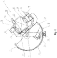
- FIG 2 shows a tipping device 10 with a wagon 22 according to FIG 1 , whereby the tilting device differs from the 1 are in a tilted position in which the tilting frame 12 is rotated about the axis of rotation D relative to the clamping arm 12 .
- the clamp arm 14 is oriented vertically due to the counterweight 18 attached to the lower portion of the clamp arm 14 .
- the platform 16, which is non-rotatably attached to the tipping frame 12, is rotated about the axis of rotation D with the tipping frame 12, so that the surface of the platform 16 on which the wagon 22 is arranged runs at an angle to the horizontal and the wagon with its side wall facing the tipping device 10 the support wall 20 is present.
- the rotational movement of the tilting frame 12 relative to the clamping arm 14 reduces the distance between the bracket 34 attached to the clamping arm 14 and the platform 16 attached to the tilting frame 12, so that in 2 illustrated tilting position, the support areas 38 of the first and second bracket arms 36, 40 rest on the upper edges of the side walls of the wagon 22.
- the wagon In the tilted position, the wagon is clamped between the bracket 34 and the platform 16 so that the wagon springs 32 are subjected to at least a force in the direction of the platform 16 .
- the tilting position shown shows the position in which the locking device 25 engages and further relative rotation of the tilting frame 12 relative to the clamping arm 14 is prevented.
- FIGS figures 1 and 2 shows the tilting device 10 according to FIGS figures 1 and 2 in a further tipping position, in which the tipping frame 12 is rotated by a maximum angle of rotation about the axis of rotation D, so that the wagon 22 is emptied. In this position, the maximum force acts on the bracket 34 on the clamp arm 14.
- the Figures 1 to 3 represent a rotary movement of the tilting frame 12 in the tilting direction.
- the tipping frame 12 is moved from the in 1 rotated starting position shown in the tilting direction until the 3 shown end position is reached. Between the starting position in 1 and the end position in 3 will the in 2 reached tilted position shown, in which the locking device 25 locked, so that a relative movement between the tilting frame 12 and the clamping arm 14 is prevented. After reaching the end position according to 3 the tilting frame 12 is rotated in the opposite direction to the tilting direction, so that the in 2 illustrated tilting position is reached, in which the clamping arm is aligned substantially vertically.
- FIG 4 is an enlarged section of the tilting device 10 in the tilting position according to FIG 2 shown.
- the bracket 34 the hydraulic cylinder 42 being attached with its first, upper end to the area of the first bracket arm 36 that is supported on the clamping arm 14 and with its second, lower end to the bearing area 38 of the second bracket arm 40. It is also conceivable to attach the hydraulic cylinder between the second bracket arm 40 and the clamping arm 14, for example.
- the wagon 22 is filled with bulk material, for example, with the weight of the bulk material in the wagon 22 acting on the wagon springs 32 with a force.
- the weight of the bulk material is removed from the wagon and the force acting on the wagon springs 32 is lower, so that the wagon springs 32 apply a force to the bracket 34 .
- This force resulting from the difference in wagon weight before and after emptying is conducted via the bracket 34 into the clamp arm 14 and causes the locking device 25 to be braced between the clamp arm 14 and the tilting frame 12, so that it is difficult to release the lock.
- the arrangement of the hydraulic cylinder 42 prevents such a distortion of the locking device 25, as described below with reference to FIG figure 5 described.
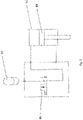
- figure 5 shows a schematic representation of a hydraulic circuit of the hydraulic cylinder 42 of FIG Figures 1 - 4 .
- a piston 44 is arranged in the hydraulic cylinder and is located in figure 5 located approximately in the middle of the hydraulic cylinder and divides the hydraulic cylinder into two chambers.
- the hydraulic cylinder is connected to a pressure accumulator 48 via a solenoid control valve 46, the solenoid control valve being a two-way valve with a check valve that implements a closed valve position and a passage that implements an open valve position. in the in figure 5 illustrated closed position of the solenoid control valve 46, a hydraulic flow from the hydraulic cylinder to the pressure accumulator is prevented via the check valve.
- position of the magnetic control valve 46 corresponds to the position in the tilted positions Figures 1 to 3 , in which the tilting process from the starting position in 1 to the end position in 3 is shown.
- the solenoid control valve 46 is in the in figure 5 shown position.
- the magnetic control valve 46 switched from the closed position to the open position when the tilting frame 12 reached a specific angle of rotation.
- the angle of rotation at which the solenoid control valve controls the hydraulic flow between the Hydraulic cylinder 42 and the pressure accumulator 48 releases covers a range of about 40 ° to 90 °, in particular about 50 ° to 70 °.
- the solenoid control valve 46 is moved from the closed to the open position prior to releasing the latch.
- the solenoid control valve 46 is moved back into the closed position, with the piston 44 remaining in the retracted position due to the resultant forces acting on it.
- the solenoid control valve 46 is moved back into the closed position, in particular before the locking device 25 is unlocked.
- the locking device 25 is opened and when the limit in 2 shown position, the bracket 34 is lifted from the wagon 22.
- a check valve is arranged between the hydraulic cylinder 42 and the pressure accumulator 48, so that a hydraulic flow from the pressure accumulator 48 to the hydraulic cylinder 42 is possible.
- the in figure 5 shown position of the piston 44 in the hydraulic cylinder is reached again.
Landscapes
- Engineering & Computer Science (AREA)
- Aviation & Aerospace Engineering (AREA)
- Mechanical Engineering (AREA)
- Handcart (AREA)
- Forklifts And Lifting Vehicles (AREA)
- Agricultural Machines (AREA)
Description
- Die Erfindung betrifft eine Kippvorrichtung zum Entleeren von Materialien, vorzugsweise Schüttgut, aus oben offenen Waggons, sowie ein Verfahren zum Betreiben einer Kippvorrichtung.
- Kippvorrichtungen werden üblicherweise zum Entleeren von mit Schüttgut beladenen Wagons, insbesondere Zugwagons, eingesetzt. In der
DE 10 2008 047 716 werden die Wagon zum Entleeren in der Kippvorrichtung verklemmt und um eine Drehachse um etwa 130° - 180° gedreht, sodass der Wagoninhalt beispielsweise in einen Bunker geschüttet wird. Der Wagon weist üblicherweise ein Fahrwerk mit einer Wagonfeder auf und steht während des Kippvorgangs auf einer Plattform der Kippvorrichtung.US 3 811 580 A offenbart außerdem eine Kippvorrichtung gemäß dem Oberbegriff des Anspruchs 1. - Nach der Entleerung des Wagons wird dieser um die Drehachse in die Ausgangsposition gedreht, wobei der Wagon ein um das Gewicht des Wagoninhalts reduziertes Gewicht aufweist. Die Gewichtsdifferenz sorgt für eine über die Wagonfeder aufgebrachte Verspannung der Kippvorrichtung, was insbesondere in einem hohen Verschleiß oder einem Bruch von Komponenten der Kippvorrichtung resultiert.
- Davon ausgehend ist es Aufgabe der vorliegenden Erfindung, eine Kippvorrichtung sowie ein Verfahren zum Betreiben einer Kippvorrichtung bereitzustellen, wobei Verspannungen innerhalb der Kippvorrichtung zuverlässig minimiert werden.
- Diese Aufgabe wird durch eine Kippvorrichtung mit den Merkmalen des unabhängigen Vorrichtungsanspruchs 1 gelöst. Vorteilhafte Weiterbildungen ergeben sich aus den abhängigen Ansprüchen.
- Eine Kippvorrichtung zum Entleeren von Materialien, vorzugsweise Schüttgut, aus insbesondere oben offenen Waggons umfasst nach einem ersten Aspekt einen Kipprahmen, der um eine Drehachse drehbar ist, eine mit dem Kipprahmen verbundene Plattform zur Aufnahme zumindest eines Waggons, einen an dem Kipprahmen drehbar angebrachten Klemmarm, eine Verriegelungseinrichtung zum Verhindern einer relativen Bewegung zwischen dem Kipprahmen und dem Klemmarm und einen Bügel, der derart an dem Klemmarm angebracht ist, dass er in einer Kippposition der Kippvorrichtung, bei welcher der Kipprahmen um die Drehachse gedreht ist, zumindest teilweise auf einer oberen Kante zumindest einer Seitenwand des Waggons anliegt, wobei an dem Bügel ein Hydraulikzylinder derart angebracht ist, dass er während eines Kippvorgangs auftretende Verspannungen der Kippvorrichtung, insbesondere in der Verriegelungseinrichtung, zumindest teilweise kompensiert.
- Bei der Kippvorrichtung handelt es sich vorzugsweise um einen Seitenkipper, wobei die Drehachse des Kipprahmens die Wagonmittelachse ist oder einen Seitenhochkipper, bei dem die Drehachse des Kipprahmens oberhalb der Mittelachse eines sich in der Kippvorrichtung befindenden Wagons liegt. Das Schüttgut umfasst beispielsweise Rohstoffe, wie Kohle oder Erze. Bei dem Wagon handelt es sich beispielsweise um einen Wagon eines Güterzugs, der oben offen oder zumindest zu öffnen ist, sodass sich in dem Wagon befindendes Schüttgut durch Drehen des Wagons ausgekippt werden kann. Der Wagon weist vorzugsweise ein Fahrwerk mit Wagonfedern auf.
- Die Kippvorrichtung ist vorzugsweise von einer Ausgangsposition, in der die Oberfläche der Plattform im Wesentlichen horizontal ausgerichtet ist, sodass ein Verfahren des Wagons in die Kippvorrichtung hinein oder aus der Kippvorrichtung heraus möglich ist, in eine Kippposition bewegbar, in der der Kipprahmen um einen Drehwinkel um die Drehachse gedreht ist. Unter der Kippposition ist jede Position zu verstehen, bei welcher der Kipprahmen um die Drehachse relativ zur Ausgangsposition gedreht ist. Unter einer Drehung in Kipprichtung ist eine Drehung von der Ausgangsposition in die Endposition des Kippvorgangs, in der der Kipprahmen etwa 130°- 180° gedreht ist, zu verstehen.
- Der Kipprahmen umfasst vorzugsweise einen Antriebsring, der im Wesentlichen halbkreisförmig ausgebildet ist und ein Zahnprofil aufweist. Der Antriebsring steht mit einer Antriebseinrichtung im Eingriff, sodass sich bei einem Antrieb der Kippvorrichtung der Kipprahmen um die Drehachse dreht und der Antriebsring eine im Wesentlichen kreisförmige Bewegung ausführt. Der Durchmesser des im Wesentlichen halbkreisförmigen Kipprahmens übersteigt die Höhe des Wagons, sodass dieser durch eine Drehbewegung auskippbar ist.
- Auf der Oberfläche der Plattform sind vorzugsweise Schienen angebracht, auf denen der Wagon in die Kippvorrichtung führbar ist. Die Plattform ist drehfest direkt oder über einen Verbindungsarm an dem Kipprahmen angebracht, sodass die Plattform die Drehbewegung des Kipprahmens ausführt.
- Der Klemmarm erstreckt sich in Richtung der Drehachse des Kipprahmens über zumindest eine Wagonlänge, sodass zumindest ein Wagon, vorzugsweise zwei Wagons, in der Kippvorrichtung aufnehmbar sind. Die drehbare Anbringung des Klemmarms an dem Kipprahmen ermöglicht eine relative Bewegung des Kipprahmens zu dem Klemmarm. Der obere Bereich des Klemmarms erstreckt sich in einem Winkel zu dem unteren Bereich des Klemmarms, sodass sich bei einer Drehung des Kipprahmens in Kipprichtung der obere Bereich des Klemmarms und die Plattform aufeinander zu bewegen, sodass der Wagon zwischen dem Kipprahmen und dem Klemmarm fixierbar ist. Ferner weist der Klemmrahmen vorzugsweise ein Gegengewicht auf, das derart an dem Klemmarm angebracht ist, dass es für eine vertikale Ausrichtung des unteren Bereichs des Klemmarms in der Ausgangsposition sorgt.
- Der insbesondere an dem oberen Bereich des Klemmarms, zwischen Klemmarm und Plattform angebrachten Bügel kommt bei einer Drehung des Klemmarms in Kipprichtung auf der oberen Kante der Seitenwände des Wagons zum Anliegen. Der Bügel ist vorzugsweise bewegbar, insbesondere drehbar, an dem Klemmarm angebracht, sodass er für eine optimale Fixierung von Wagons unterschiedlicher Höhe und Breite in der Kippeinrichtung sorgt.
- Die Verriegelungseinrichtung verhindert in einer Verriegelungsposition eine relative Bewegung des Kipprahmens und des Klemmarms. Bei einer solchen Verriegelungseinrichtung handelt es sich beispielsweise um einen Bolzen oder eine Einrastverriegelung, die beispielsweise derart ausgebildet ist, dass sie eine relative Bewegung des Klemmarms und des Kipprahmens in einer Richtung, insbesondere entgegen der Kipprichtung, verhindert.
- Bei einem Kippvorgang wird der Kipprahmen in Kipprichtung gedreht, sodass sich der Raum zwischen dem Bügel und der Plattform verringert bis der Wagon zwischen diesen geklemmt wird. Der Klemmrahmen wird um die Drehachse in die Endposition gedreht, wobei der Wagon entleert wird. Anschließend wird der Kipprahmen entgegen der Kipprichtung in die Ausgangsposition gedreht. Im entladenen Zustand ist das Gewicht des Wagons geringer, sodass die Wagonfedern den Bügel mit einer Kraft beaufschlagt und Verspannungen innerhalb der Kippvorrichtung, insbesondere in der Verriegelungseinrichtung, verursacht.
- Der an dem Bügel angebrachte Hydraulikzylinder ermöglicht einen Ausgleich der über die Wagonfeder auf den Bügel aufgebrachten Kräfte, sodass Verspannungen innerhalb der Kippvorrichtung nach dem Entleeren des Wagons und während des Drehens entgegen der Kipprichtung in die Ausgangsposition zuverlässig vermieden werden. Durch den Hydraulikzylinder werden die durch die Gewichtsdifferenz des Wagons vor und nach dem Kippvorgang auftretenden Wagonfederkräfte gezielt kompensiert, unabhängig von dem Gewicht des Wagoninhalts. Ein Verschleiß oder das Risiko eines Bruchs der Verriegelungseinrichtung wird minimiert.
- Die Anordnung des Hydraulikzylinders an dem Bügel ermöglicht eine einfache Installation des Hydraulikzylinders, der zur Kompensation der Wagonkraft ausgebildet ist.
- Erfindungsgemäß ist der Hydraulikzylinder zwischen dem Bügel und dem Klemmarm angeordnet. Dies ermöglicht einen Ausgleich der zwischen dem Bügel und dem Klemmarm wirkenden Kräfte, die über die Wagonfedern in den Bügel eingeleitet werden. Der Hydraulikzylinder ist vorzugsweise mit seinem einen Ende an dem Klemmarm und mit seinem anderen Ende an dem Bügel angebracht.
- Der Bügel weist gemäß einer weiteren Ausführungsform einen ersten Bügelarm und einen relativ zu dem ersten Bügelarm drehbaren zweiten Bügelarm auf, wobei der Hydraulikzylinder zwischen dem ersten Bügelarm und dem zweiten Bügelarm angeordnet ist. Dies ermöglicht eine Kompensation der Wagonfederkräfte über eine relative Bewegung der Bügelarme zueinander.
- Der Hydraulikzylinder ist gemäß einer weiteren Ausführungsform derart an dem Bügel angebracht, dass er den Bügel in der Kippposition der Kippvorrichtung mit einer Kraft in Richtung der Plattform beaufschlagt.
- Gemäß einer weiteren Ausführungsform ist ein hydraulischer Druckspeicher angeordnet, der mit dem Hydraulikzylinder in Verbindung steht. Ein hydraulischer Druckspeicher ermöglicht eine passive Regelung des Hydraulikzylinders und realisiert eine einfache und kostengünstige Installation des Hydraulikzylinders in der Kippvorrichtung.
- Zwischen dem Hydraulikzylinder und dem Druckspeicher ist gemäß einer weiteren Ausführungsform ein Ventil, insbesondere ein Magnetstellventil, angeordnet. Das Magnetstellventil ist vorzugsweise elektrisch ansteuerbar.
- Gemäß einer weiteren Ausführungsform umfasst das Ventil eine geöffnete Position, in der Hydraulikflüssigkeit von dem Hydraulikzylinder in den Druckspeicher strömen kann und eine geschlossene Position, in der ein Rückschlagventil ein Strömen von Hydraulikflüssigkeit von dem Hydraulikzylinder in den Druckspeicher verhindert. Dies ermöglicht eine einfache Regelung des Drucks in dem Hydraulikzylinder.
- Der Waggon weist gemäß einer weiteren Ausführungsform ein Fahrgestell und eine Wagonfeder auf, wobei der Hydraulikzylinder derart angeordnet ist, dass er der Wagonfeder entgegenwirkt. Dies ermöglicht einen optimalen Ausgleich der von der Wagonfeder auf die Kippvorrichtung aufgebrachten Kräfte.
- Weiterhin umfasst die Erfindung ein Verfahren zum Betreiben einer voran beschriebenen Kippvorrichtung, wobei die Kippvorrichtung einen hydraulischen Druckspeicher aufweist ist, der mit dem Hydraulikzylinder in Verbindung steht. Das Verfahren umfassend die Schritte:
- a) Drehen des Kipprahmens in Kipprichtung um die Drehachse D,
- b) Aktivieren der Verriegelungseinrichtung, sodass eine relative Bewegung zwischen dem Kipprahmen und dem Klemmarm verhindert wird,
- c) Drehen des Kipprahmens in Kipprichtung um die Drehachse D um einen Winkel von etwa 130° - 180°,
- d) Drehen des Kipprahmens entgegen der Kipprichtung um die Drehachse D,
- e) Strömen von Hydraulikflüssigkeit von dem Hydraulikzylinder in den Druckspeicher,
- f) Lösen der Verriegelungseinrichtung, sodass eine relative Bewegung zwischen dem Kipprahmen und dem Klemmarm ermöglicht wird.
- Der Schritt e) ermöglicht einen Druckausgleich der durch die Gewichtsdifferenz des Wagons zusätzlich auf den Hydraulikzylinder wirkenden Kraft der Wagonfeder, wobei eine Verspannung der arretierten Verriegelungseinrichtung verhindert wird.
- Die Kippvorrichtung weist gemäß einer weiteren Ausführungsform ein Ventil auf, das eine geöffnete Position, in der Hydraulikflüssigkeit von dem Hydraulikzylinder in den Druckspeicher strömen kann, und eine geschlossene Position umfasst, in der ein Rückschlagventil ein Strömen von Hydraulikflüssigkeit von dem Hydraulikzylinder in den Druckspeicher verhindert und wobei der Schritt e) das Bewegen des Ventils in die geöffnete Position umfasst. Dadurch wird ein Strom von Hydraulikflüssigkeit von dem Hydraulikzylinder zu dem Druckspeicher und somit ein Druckausgleich zwischen dem Hydraulikzylinder und dem Druckspeicher ermöglicht.
- Zwischen den Schritten e) und f) wird gemäß einer weiteren Ausführungsform das Ventil in die geschlossene Position bewegt wird. Dadurch wird ein konstanter Druck in dem Hydraulikzylinder vor dem Öffnen der Verriegelungseinrichtung erreicht.
- Die voran beschriebene Kippvorrichtung und das Verfahren zum Betreiben einer Kippvorrichtung ermöglichen einen Druckausgleich innerhalb der Kippvorrichtung während des Kippvorgangs, wodurch Verspannungen in der Kippvorrichtung und insbesondere in der Verriegelungseinrichtung zuverlässig vermieden werden.
- Die Erfindung ist nachfolgend anhand mehrerer Ausführungsbeispiele mit Bezug auf die beiliegenden Figuren näher erläutert.
- Fig. 1
- zeigt eine schematische Darstellung einer Kippvorrichtung mit einem Wagon in der Ausgangsposition gemäß einem Ausführungsbeispiel.
- Fig. 2
- zeigt eine schematische Darstellung einer Kippvorrichtung mit einem Wagon gemäß dem Ausführungsbeispiel in
Fig.1 in einer Kippposition. - Fig. 3
- zeigt eine schematische Darstellung einer Kippvorrichtung mit einem Wagon gemäß dem Ausführungsbeispiel in
Fig.1 in einer weiteren Kippposition. - Fig. 4
- zeigt eine vergrößerte Darstellung eines Ausschnitts einer Kippvorrichtung aus
Fig. 2 . - Fig. 5
- zeigt eine schematische Darstellung einer Hydraulikschaltung des Hydraulikzylinders der
Fig. 1 - 4 . -
Fig. 1 zeigt eine Kippvorrichtung 10, in der sich ein Wagon 22 befindet. Die Kippvorrichtung 10 weist einen Kipprahmen 12 auf, der in etwa halbkreisförmig ausgebildet ist. Der Kipprahmen 12 weist einen Antriebsring mit einer Verzahnung auf, die sich über den halbkreisförmig ausgebildeten Umfangsbereich erstreckt und mit einer bodenseitig angeordneten Antriebseinrichtung 26 zusammenwirkt. Ferner weist die Kippvorrichtung 10 einen Klemmarm 14 auf der mit dem Kipprahmen 12 um eine Drehachse D drehbar verbunden ist. Die Drehachse D ist in etwa in dem Kreismittelpunkt des Halbkreisförmigen Kipprahmens 12 angeordnet. Der Klemmarm 14 weist einen ersten sich in der inFig. 1 dargestellten Ausgangsposition in etwa senkrecht erstreckenden Bereich auf, der einen im wesentlichen rechteckigen Querschnitt aufweist, wobei in etwa durch den Mittelpunkt dieses Bereichs die Drehachse D verläuft. An das obere Ende des ersten Bereichs schließt sich ein zweiter Bereich an, der sich in etwa 45° zu dem ersten Bereich erstreckt und einen im Wesentlichen Rechteckigen Querschnitt aufweist. Der Klemmarm 14 erstreckt sich ferner in Richtung der Drehachse D, sodass er beispielsweise zwei Wagonlängen aufweist. Am unteren Ende des ersten Bereichs des Klemmarms 14 ist ein Gegengewicht 18 angebracht, das einen im Wesentlichen rechteckigen Querschnitt aufweist und sich in etwa in einem 45° Winkel zu dem ersten Bereich des Klemmarms 14 erstreckt. - Die Kippvorrichtung 10 weist ferner eine Plattform 16 zur Aufnahme zumindest eines Wagons auf. Die Plattform ist mit dem Kipprahmen 12 drehfest verbunden und weist eine in der Ausgangsposition in
Fig. 1 horizontal verlaufende Oberfläche auf, an der zwei Schienen 28 zur Führung eines Wagons 22 angebracht sind. Des Weiteren weist die Kippvorrichtung 10 eine sich in Richtung der Drehachse D erstreckende und an der Innenseite des Kipprahmens 12 angeordnete Stützwand 20 auf, an der zumindest ein Wagon 22 in einer Kippposition gemäßFig. 2 und3 anliegt. - Auf der Plattform 16 ist ein Wagon 22 angeordnet, an dem ein auf den Schienen 28 positioniertes Fahrwerk 30 mit zwei schematisch dargestellten Wagonfedern 32 angebracht ist, die den Wagon 22 abstützen. Der Wagon ist beispielsweise mit Schüttgut beladen.
- An dem äußeren Endbereich des zweiten Bereichs des Klemmarms 14 ist oberhalb des Wagons 22 ein Bügel 34 angebracht, der sich über den zweiten Bereich des Klemmarms 14 hinweg erstreckt. Der Bügel 34 umfasst einen ersten Bügelarm 36 und einen zweiten Bügelarm 40, die über eine Halterung an der Unterseite des zweiten Bereichs des Klemmarms 14 drehbar angebracht sind. Der erste Bügelarm 36 stützt sich mit seinem innenseitigen Ende an der Unterseite des zweiten Bereichs des Klemmarms 14 ab und weist an seinem äußeren Ende einen Auflagebereich 38 auf, der in Richtung des zweiten Bereichs des Klemmarms 14 verläuft. Der zweite Bügelarm 40 weist ebenfalls einen Auflagebereich 38 auf und ist drehbar mit dem ersten Bügelarm 36 über die Halterung verbunden.
- Zwischen dem ersten Bügelarm 36 und dem zweiten Bügelarm 40 ist ein Hydraulikzylinder 42 derart angeordnet, dass er den ersten und den zweiten Bügel zueinander beabstandet.
- Die Kippvorrichtung 10 weist ferner eine Verriegelungseinrichtung 25 auf, die beispielsweise an dem Gegengewicht 18 angebracht ist eine relative Bewegung des Kipprahmens zu dem Klemmarm 14 verhindert. Bei einer solchen Verriegelung kann es sich beispielsweise um einen Bolzen oder eine Einrastverbindung handeln, die beispielsweise automatisch ab Erreichen eines bestimmten Drehwinkels des Kipprahmens 12 zu dem Klemmarm 14 verriegelbar bzw. lösbar ist. Die Verriegelung kann ferner derart ausgebildet sein, dass sie eine relative Drehung des Klemmrahmens zu dem Klemmarm nur in eine Richtung verhindert, sodass beispielsweise eine Drehung entgegen der Klemmrichtung verhindert wird.
-
Fig. 2 zeigt eine Kippvorrichtung 10 mit einem Wagon 22 gemäßFig. 1 , wobei sich die Kippvorrichtung im Unterschied zurFig. 1 in einer Kippposition befinden, in der der Kipprahmen 12 relativ zu dem Klemmarm 12 um einen um die Drehachse D gedreht ist. Der Klemmarm 14 ist aufgrund des an dem unteren Bereich des Klemmarms 14 angebrachten Gegengewichts 18 senkrecht ausgerichtet. - Die drehfest an dem Kipprahmen 12 angebrachte Plattform 16 ist mit dem Kipprahmen 12 um die Drehachse D gedreht, sodass die Oberfläche der Plattform 16, auf der der Wagon 22 angeordnet ist, schräg zur Horizontalen verläuft und der Wagon mit seiner zur Kippvorrichtung 10 gewandten Seitenwand an der Stützwand 20 anliegt.
- Durch die Drehbewegung des Kipprahmens 12 relativ zu dem Klemmarm 14 verringert sich der Abstand zwischen dem an dem Klemmarm 14 angebrachten Bügel 34 und der an dem Kipprahmen 12 angebrachten Plattform 16, sodass in der in
Fig. 2 dargestellten Kippposition, die Auflagebereiche 38 des ersten und des zweiten Bügelarms 36, 40 auf den Oberkanten der Seitenwände des Wagons 22 anliegen. Der Wagon wird in der Kippposition zwischen den Bügel 34 und der Plattform 16 geklemmt, sodass die Wagonfedern 32 zumindest mit einer Kraft in Richtung der Plattform 16 beaufschlagt werden. - Die in
Fig. 2 dargestellte Kippposition zeigt die Position, in welcher die Verriegelungseinrichtung 25 einrastet und eine weitere relative Drehung des Kipprahmens 12 relativ zu dem Klemmarm 14 verhindert. -
Fig. 3 zeigt die Kippvorrichtung 10 gemäß denFiguren 1 und2 in einer weiteren Kippposition, in der der Kipprahmen 12 um einen maximalen Drehwinkel um die Drehachse D gedreht ist, sodass der Wagon 22 entleert wird. In dieser Position wirkt die maximale Kraft über den Bügel 34 auf den Klemmarm 14. DieFiguren 1 bis 3 stellen eine Drehbewegung des Kipprahmens 12 in Kipprichtung dar. - Zur Durchführung eines Kippvorgangs wird der Kipprahmen 12 von der in
Fig. 1 dargestellten Ausgangsposition in Kipprichtung gedreht bis dieFig. 3 dargestellte Endposition erreicht ist. Zwischen der Ausgangsstellung inFig. 1 und der Endposition inFig. 3 wird die inFig. 2 dargestellte Kippposition erreicht, bei welcher die Verriegelungseinrichtung 25 arretiert, sodass eine Relativbewegung zwischen dem Kipprahmen 12 und dem Klemmarm 14 verhindert wird. Nach Erreichen der Endposition gemäßFig. 3 wird der Kipprahmen 12 entgegen der Kipprichtung gedreht, sodass die inFig. 2 dargestellte Kippposition erreicht wird, in der der Klemmarm im Wesentlichen senkrecht ausgerichtet ist. In dieser Kippposition wird bei einer Drehung des Kipprahmens 12 entgegen der Kipprichtung die Verriegelung zwischen dem Kipprahmen 12 und dem Klemmarm 14 gelöst, sodass eine Relativbewegung zwischen diesen möglich ist. Anschließend wird der Kipprahmen 12 in die Ausgangsposition gemäßFig. 1 gedreht, sodass der entleerte Wagon die Kippvorrichtung 10 verlassen kann. - In
Fig. 4 ist ein vergrößerter Ausschnitt der Kippvorrichtung 10 in der Kippposition gemäßFig. 2 gezeigt. Insbesondere zeigtFig. 4 den Bügel 34, wobei der Hydraulikzylinder 42 mit seinem ersten, oberen Ende an dem sich an den Klemmarm 14 abstützenden Bereich des ersten Bügelarms 36 und mit seinem zweiten, unteren Ende an dem Auflagebereich 38 des zweiten Bügelarms 40 angebracht ist. Es ist ebenfalls denkbar, den Hydraulikzylinder beispielsweise zwischen dem zweiten Bügelarm 40 und dem Klemmarm 14 anzubringen. - In der in
Fig. 1 dargestellten Ausgangsposition ist der Wagon 22 beispielsweise mit Schüttgut gefüllt, wobei die Gewichtskraft des Schüttguts in dem Wagon 22 die Wagonfedern 32 mit einer Kraft beaufschlagt. Nach dem Entleeren des Wagons 22 ist der Wagon um das Gewicht des Schüttguts erleichtert und die auf die Wagonfedern 32 wirkende Kraft ist geringer, sodass die Wagonfedern 32 den Bügel 34 mit einer Kraft beaufschlagen. Diese aus der Differenz des Wagongewichts vor und nach dem Entleeren resultierende Kraft wird über den Bügel 34 in den Klemmarm 14 geleitet und bewirkt eine Verspannung der Verriegelungseinrichtung 25 zwischen dem Klemmarm 14 und dem Kipprahmen 12, sodass ein Lösen der Verriegelung schwierig ist. Die Anordnung des Hydraulikzylinders 42 verhindert eine solche Verspannung der Verriegelungseinrichtung 25, wie nachfolgend mit Bezug aufFig. 5 beschrieben. -
Fig. 5 zeigt eine schematische Darstellung einer Hydraulikschaltung des Hydraulikzylinders 42 derFig. 1 - 4 . In dem Hydraulikzylinder ist ein Kolben 44 angeordnet, der sich inFig. 5 in etwa auf der Mitte des Hydraulikzylinders befindet und den Hydraulikzylinder in zwei Kammern teilt. Der Hydraulikzylinder ist über ein Magnetstellventil 46 mit einem Druckspeicher 48 verbunden, wobei das Magnetstellventil ein zwei-Wegeventil ist mit einem Rückschlagventil, das eine geschlossene Ventilstellung realisiert, und einem Durchlass, der eine geöffnete Ventilstellung realisiert. In der inFig. 5 dargestellten geschlossenen Stellung des Magnetstellventils 46 wird ein Hydraulikstrom von dem Hydraulikzylinder zu dem Druckspeicher über das Rückschlagventil verhindert. - Die in
Fig. 5 gezeigte Stellung des Magnetstellventils 46 entspricht der Stellung in den Kipppositionen derFiguren 1 bis 3 , in denen der Kippvorgang von der Ausgangsposition inFig. 1 bis zur Endposition inFig. 3 dargestellt ist. - Während des Kippvorgangs, bei der Drehung des Kipprahmens 12 in Kipprichtung, befindet sich das Magnetstellventil 46 in der in
Fig. 5 dargestellten Stellung. Während der Drehung des Kipprahmens 12 entgegen der Kipprichtung schaltete das Magnetstellventil 46 bei Erreichen eines bestimmten Drehwinkels des Kipprahmens 12 von der geschlossenen Stellung in die geöffnete Stellung. Der Drehwinkel, bei dem das Magnetstellventil den Hydraulikstrom zwischen dem Hydraulikzylinder 42 und dem Druckspeicher 48 freigibt umfasst einen Bereich von etwa 40° bis 90 °, insbesondere etwa 50° bis 70°. Vorzugsweise wird das Magnetstellventil 46 vor dem Lösen der Verriegelung von der geschlossenen in die geöffnete Stellung bewegt. - Im der geöffneten Position des Magnetstellventils strömt Hydraulikflüssigkeit von dem Hydraulikzylinder 42 zu dem Druckspeicher 48, wobei sich der Kolben 44 aufgrund der auf den Kolben 44 wirkenden Kraft der Wagonfedern 32 in den Hydraulikzylinder 42 bewegt bis er das Ende des Hydraulikzylinders 42 erreicht hat oder eine Kompensation der aus der Differenz des Wagongewichts vor und nach dem Entleeren resultierenden Kraft erreicht wurde. Das Öffnen des Magnetstellventils 46 bewirkt zumindest einen teilweisen Ausgleich der Kräfte innerhalb der Kippvorrichtung 10, wobei eine Verspannung der Verriegelungseinrichtung 25 vermieden wird.
- Während des weiteren Kippvorgangs entgegen der Kipprichtung wird das Magnetstellventil 46 wieder in die geschlossenen Position bewegt, wobei der Kolben 44 aufgrund der auf ihn wirkenden resultierenden Kräfte in der eingefahrenen Position verbleibt. Das Magnetstellventil 46 wird insbesondere vor Entriegelung der Verriegelungseinrichtung 25 zurück in die geschlossenen Position bewegt. Beim Erreichen der in
Fig. 2 dargestellten Kippposition wird die Verriegelungseinrichtung 25 geöffnet und beim Überschreiten der inFig. 2 dargestellten Position wird der Bügel 34 von dem Wagon 22 abgehoben. In der geschlossenen Stellung des Magnetstellventils 46 ist zwischen dem Hydraulikzylinder 42 und dem Druckspeicher 48 ein Rückschlagventil angeordnet, sodass ein Hydraulikstrom von dem Druckspeicher 48 zu dem Hydraulikzylinder 42 möglich ist. Vor dem Erreichen der inFig. 1 dargestellten Ausgangsposition wird die inFig. 5 dargestellte Stellung des Kolbens 44 in dem Hydraulikzylinder wieder erreicht. - Die voran beschriebene Anordnung ermöglicht einen Ausgleich der durch die Entleerung des Wagons auftretenden Kräfte, wobei Verspannungen innerhalb der Kippvorrichtung zuverlässig vermieden werden und ein hoher Verschleiß oder Bruch der Verriegelungseinrichtung 25 verhindert wird.
-
- 10
- Kippvorrichtung
- 12
- Kipprahmen
- 14
- Klemmarm
- 16
- Plattform
- 18
- Gegengewicht
- 20
- Stützwand
- 22
- Wagon
- 24
- Antriebsring
- 25
- Verriegelungseinrichtung
- 26
- Antriebseinrichtung
- 28
- Schienen
- 30
- Fahrwerk
- 32
- Wagonfeder
- 34
- Bügel
- 36
- erster Bügelarm
- 38
- Auflagebereich
- 40
- zweiter Bügelarm
- 42
- Hydraulikzylinder
- 44
- Kolben
- 46
- Magnetstellventil
- 48
- Druckspeicher
Claims (11)
- Kippvorrichtung (10) zum Entleeren von Materialien, vorzugsweise Schüttgut, aus Wagons (22) aufweisendeinen Kipprahmen (12), der um eine Drehachse (D) drehbar ist,eine mit dem Kipprahmen (12) verbundene Plattform (16) zur Aufnahme zumindest eines Wagons (22),einen an dem Kipprahmen (12) drehbar angebrachten Klemmarm (14),eine Verriegelungseinrichtung (25) zum Verhindern einer relativen Bewegung zwischen dem Kipprahmen (12) und dem Klemmarm (14), wobei die Verriegelungseinrichtung (25) einen Bolzen oder eine Einrastverbindung bildet, undeinen Bügel (34), der derart an dem Klemmarm (14) angebracht ist, dass er in einer Kippposition der Kippvorrichtung (10), bei welcher der Kipprahmen (12) um die Drehachse gedreht ist, zumindest teilweise auf einer oberen Kante zumindest einer Seitenwand des Wagons (22) anliegt,dadurch gekennzeichnet, dassan dem Bügel (34) ein Hydraulikzylinder (42) derart angebracht ist, dass er während eines Kippvorgangs auftretende Verspannungen der Kippvorrichtung (10), insbesondere in der Verriegelungseinrichtung (25), zumindest teilweise kompensiert,wobei der Hydraulikzylinder (42) zwischen dem Bügel (34) und dem Klemmarm (14) angeordnet ist.
- Kippvorrichtung (10) nach Anspruch 1, wobei der Bügel (34) einen ersten Bügelarm (36) und einen relativ zu dem ersten Bügelarm (36) drehbaren zweiten Bügelarm (40) aufweist und wobei der Hydraulikzylinder (42) zwischen dem ersten Bügelarm (36) und dem zweiten Bügelarm (40) angeordnet ist.
- Kippvorrichtung (10) nach einem der vorangehenden Ansprüche, wobei der Hydraulikzylinder (42) derart an dem Bügel (34) angebracht ist, dass er den Bügel (34) in der Kippposition der Kippvorrichtung (10) mit einer Kraft in Richtung der Plattform (16) beaufschlagt.
- Kippvorrichtung (10) nach einem der vorangehenden Ansprüche, wobei ein hydraulischer Druckspeicher (48) angeordnet ist, der mit dem Hydraulikzylinder (42) in Verbindung steht.
- Kippvorrichtung (10) nach Anspruch 4, wobei zwischen dem Hydraulikzylinder (42) und dem Druckspeicher (42) ein Ventil (46), insbesondere ein Magnetstellventil angeordnet ist.
- Kippvorrichtung (10) nach Anspruch 5, wobei das Ventil (46) eine geöffnete Position, in der Hydraulikflüssigkeit von dem Hydraulikzylinder (42) in den Druckspeicher (48) strömen kann, und eine geschlossene Position umfasst, in der ein Rückschlagventil ein Strömen von Hydraulikflüssigkeit von dem Hydraulikzylinder (42) in den Druckspeicher (48) verhindert.
- Kippvorrichtung (10) nach einem der vorangehenden Ansprüche, wobei der Wagon (22) ein Fahrgestell (30) und eine Wagonfeder (32) aufweist, wobei der Hydraulikzylinder (42) zur Wirkung gegen die Wagonfeder (32) angeordnet ist.
- Verfahren zum Betreiben einer Kippvorrichtung (10) nach einem der vorrangehenden Ansprüche, wobei die Kippvorrichtung (10) einen hydraulischen Druckspeicher (48) aufweist ist, der mit dem Hydraulikzylinder (42) in Verbindung steht, umfassend die Schritte:a) Drehen des Kipprahmens (12) in Kipprichtung um die Drehachse (D),b) Aktivieren der Verriegelungseinrichtung (25), sodass eine relative Bewegung zwischen dem Kipprahmen (12) und dem Klemmarm (14) verhindert wird,c) Drehen des Kipprahmens (12) in Kipprichtung um die Drehachse (D) um einen Winkel von etwa 130° - 180°,d) Drehen des Kipprahmens (12) entgegen der Kipprichtung um die Drehachse (D),e) Strömen von Hydraulikflüssigkeit von dem Hydraulikzylinder (42) in den Druckspeicher (48),f) Lösen der Verriegelungseinrichtung (25), sodass eine relative Bewegung zwischen dem Kipprahmen (12) und dem Klemmarm (14) ermöglicht wird.
- Verfahren nach Anspruch 8, wobei die Kippvorrichtung (10) ein Ventil (46) aufweist, das eine geöffnete Position, in der Hydraulikflüssigkeit von dem Hydraulikzylinder (42) in den Druckspeicher (48) strömen kann, und eine geschlossene Position umfasst, in der ein Rückschlagventil ein Strömen von Hydraulikflüssigkeit von dem Hydraulikzylinder (42) in den Druckspeicher (48) verhindert und wobei der Schritt e) das Bewegen des Ventils (46) in die geöffnete Position umfasst.
- Verfahren nach Anspruch 8 oder 9, wobei zwischen dem Schritt e) und f) das Ventil (46) in die geschlossene Position bewegt wird.
- Verfahren nach einem der Ansprüche 8 bis 10, wobei während der Schritte a) bis d) das Ventil (46) in der geschlossenen Position ist.
Applications Claiming Priority (2)
| Application Number | Priority Date | Filing Date | Title |
|---|---|---|---|
| DE102015000667.3A DE102015000667A1 (de) | 2015-01-23 | 2015-01-23 | Kippvorrichtung sowie Verfahren zum Betreiben einer Kippvorrichtung |
| PCT/EP2016/050598 WO2016116339A1 (de) | 2015-01-23 | 2016-01-14 | Kippvorrichtung sowie verfahren zum betreiben einer kippvorrichtung |
Publications (2)
| Publication Number | Publication Date |
|---|---|
| EP3247661A1 EP3247661A1 (de) | 2017-11-29 |
| EP3247661B1 true EP3247661B1 (de) | 2022-04-13 |
Family
ID=55135231
Family Applications (1)
| Application Number | Title | Priority Date | Filing Date |
|---|---|---|---|
| EP16700586.7A Active EP3247661B1 (de) | 2015-01-23 | 2016-01-14 | Kippvorrichtung sowie verfahren zum betreiben einer kippvorrichtung |
Country Status (11)
| Country | Link |
|---|---|
| US (1) | US10494204B2 (de) |
| EP (1) | EP3247661B1 (de) |
| CN (1) | CN107207172B (de) |
| BR (1) | BR112017014618A2 (de) |
| CA (1) | CA2968904A1 (de) |
| DE (1) | DE102015000667A1 (de) |
| PE (1) | PE20171682A1 (de) |
| RU (1) | RU2658543C1 (de) |
| UA (1) | UA119590C2 (de) |
| WO (1) | WO2016116339A1 (de) |
| ZA (1) | ZA201703931B (de) |
Families Citing this family (4)
| Publication number | Priority date | Publication date | Assignee | Title |
|---|---|---|---|---|
| AT522180B1 (de) * | 2019-06-27 | 2020-09-15 | Engel Austria Gmbh | Haltevorrichtung und Verfahren zum Montieren oder Demontieren eines vertikalen Massezylinders |
| CN114993658B (zh) * | 2022-06-16 | 2024-06-18 | 国能黄骅港务有限责任公司 | 车厢压靠检测装置 |
| CN116119396B (zh) * | 2023-03-27 | 2025-05-06 | 烟台未来自动装备有限责任公司 | 一种液压翻板卸车机平台的同步控制装置及同步控制方法 |
| CN118025846A (zh) * | 2024-03-13 | 2024-05-14 | 中国电建集团武汉重工装备有限公司 | 一种液压主动式压车的侧倾翻车机及其翻卸方法 |
Family Cites Families (19)
| Publication number | Priority date | Publication date | Assignee | Title |
|---|---|---|---|---|
| GB548894A (en) * | 1941-06-05 | 1942-10-28 | Bennis Comb Ltd | Improvements in wagon tipplers |
| US2634006A (en) * | 1947-01-31 | 1953-04-07 | Heyl & Patterson | Clamp-operating mechanism for rotary car dumpers |
| SU134195A1 (ru) * | 1960-04-25 | 1960-11-30 | В.С. Волков | Вагоноопрокидыватель |
| DE1117047B (de) * | 1960-10-15 | 1961-11-09 | Pohlig Ag J | Haltevorrichtung fuer Eisenbahnwaggons in Seitenkippern, insbesondere Kreiselkippern |
| DE1230360B (de) * | 1963-08-28 | 1966-12-08 | Beteiligungs & Patentverw Gmbh | Rundkipper |
| GB1271687A (en) * | 1969-04-22 | 1972-04-26 | Strachan & Henshaw Ltd | Improvements in or relating to tipplers |
| US3719292A (en) * | 1971-04-21 | 1973-03-06 | Fmc Corp | Clamp mechanism for rotary car dumper |
| US3760961A (en) * | 1971-11-17 | 1973-09-25 | Mc Dowell Wellman Eng Co | Load compensated car dumper clamp |
| US3777914A (en) * | 1972-04-06 | 1973-12-11 | Mcdowell Wellman Eng Co | Retractable railroad car clamp |
| GB1420621A (en) * | 1972-04-20 | 1976-01-07 | Strachan & Henshaw Ltd | Wagon tipplers |
| GB1564205A (en) | 1976-12-20 | 1980-04-02 | Drg Ltd | Rail car discharge apparatus |
| US4134503A (en) * | 1977-08-08 | 1979-01-16 | Royal Industries, Inc. | Dumping apparatus for open top of vehicles |
| GB8331736D0 (en) | 1983-11-28 | 1984-01-04 | Drg Uk Ltd | Rail car tipplers and installations |
| US4690603A (en) * | 1985-07-02 | 1987-09-01 | Heyl & Patterson, Inc. | Car dumping apparatus |
| GB8819012D0 (en) * | 1988-08-10 | 1988-09-14 | Strachan & Henshaw Ltd | Rail car dumpers |
| US5046912A (en) * | 1988-12-23 | 1991-09-10 | Rail Engineering, Inc. | Car dumper |
| DE102006044976B3 (de) * | 2006-09-23 | 2008-05-08 | ThyssenKrupp Fördertechnik GmbH | Verfahren zum Entleeren von Waggons mit Hilfe eines Seitenhochkippers und Seitenhochkipper |
| DE102008047716B8 (de) | 2008-09-18 | 2010-08-05 | ThyssenKrupp Fördertechnik GmbH | Verfahren und Drehkipper zum Entleeren von oben offenen Eisenbahnwaggons |
| DE102010022384B4 (de) * | 2010-06-01 | 2020-10-08 | Thyssenkrupp Industrial Solutions Ag | Entladevorrichtung für offene Transportwagen |
-
2015
- 2015-01-23 DE DE102015000667.3A patent/DE102015000667A1/de not_active Withdrawn
-
2016
- 2016-01-14 RU RU2017129642A patent/RU2658543C1/ru active
- 2016-01-14 CA CA2968904A patent/CA2968904A1/en not_active Abandoned
- 2016-01-14 CN CN201680006032.XA patent/CN107207172B/zh active Active
- 2016-01-14 US US15/544,406 patent/US10494204B2/en active Active
- 2016-01-14 UA UAA201708571A patent/UA119590C2/uk unknown
- 2016-01-14 BR BR112017014618-5A patent/BR112017014618A2/pt not_active Application Discontinuation
- 2016-01-14 PE PE2017001189A patent/PE20171682A1/es unknown
- 2016-01-14 EP EP16700586.7A patent/EP3247661B1/de active Active
- 2016-01-14 WO PCT/EP2016/050598 patent/WO2016116339A1/de not_active Ceased
-
2017
- 2017-06-08 ZA ZA2017/03931A patent/ZA201703931B/en unknown
Also Published As
| Publication number | Publication date |
|---|---|
| RU2658543C1 (ru) | 2018-06-21 |
| US20180002121A1 (en) | 2018-01-04 |
| US10494204B2 (en) | 2019-12-03 |
| UA119590C2 (uk) | 2019-07-10 |
| ZA201703931B (en) | 2019-12-18 |
| CN107207172B (zh) | 2020-06-19 |
| PE20171682A1 (es) | 2017-11-27 |
| BR112017014618A2 (pt) | 2018-02-06 |
| CN107207172A (zh) | 2017-09-26 |
| CA2968904A1 (en) | 2016-07-28 |
| WO2016116339A1 (de) | 2016-07-28 |
| DE102015000667A1 (de) | 2016-07-28 |
| EP3247661A1 (de) | 2017-11-29 |
Similar Documents
| Publication | Publication Date | Title |
|---|---|---|
| DE1555120A1 (de) | Beladevorrichtung | |
| DE202008011526U1 (de) | Vorrichtung zum Festlegen des CC eines Containers | |
| WO2016116339A1 (de) | Kippvorrichtung sowie verfahren zum betreiben einer kippvorrichtung | |
| DE3627871C2 (de) | ||
| DE2141816A1 (de) | Tiefladeanhaengerfahrzeug | |
| DE10132361C1 (de) | Vorrichtung zur Sicherung des Mechanismus zum Heben und Senken der Passagiertür eines Flugzeuges | |
| DE1605012C3 (de) | Fahrzeug, insbesondere Eisenbahnwagen mit aufklappbarem Dach | |
| DE2200879A1 (de) | Einrichtung zum anheben von lasten | |
| DE102006014214A1 (de) | Einrichtung zum Auf- und Abladen einer Befülleinrichtung quer zu deren Transportrichtung | |
| DE2433871C3 (de) | Absetzkipper zum Aufnehmen, Kippen und Absetzen von Kippmulden, Silos, Paletten o.dgl | |
| DE102006044976B3 (de) | Verfahren zum Entleeren von Waggons mit Hilfe eines Seitenhochkippers und Seitenhochkipper | |
| EP1526036A1 (de) | Kippvorrichtung eines Kipperfahrzeugs | |
| DE3412167A1 (de) | Vorrichtung zum heben und kippen einer ladeflaeche | |
| DE102015120338A1 (de) | Passive Verriegelung für bewegliche Brücken und Verfahren zum passiven Verriegeln einer beweglichen Brücke | |
| DE102004037952A1 (de) | Kippvorrichtung für Schüttgut-Ladungsträger auf einem Schienen-Güterwagen mit Drehrahmen | |
| DE2907062C3 (de) | Lastaufnahmevorrichtung | |
| DE4205487C1 (en) | Tipping mast esp. for light emitting mast - has tipped device including piston-cylinder unit which via claw shaped holder with downwardly open recesses fits onto bearing bolt of mast foot | |
| DE202006014662U1 (de) | Seitenhochkipper zum Entleeren von Waggons | |
| CH351626A (de) | Kippwagen | |
| DE9317545U1 (de) | Schwenkbare Bordwand eines Transportfahrzeugs | |
| DE1080581B (de) | Zweiseiten-Hubkipper | |
| DE2261934A1 (de) | Bordwand | |
| DE1928733C3 (de) | Lade- und Entladevorrichtung für sperrige Lasten | |
| DE2410771A1 (de) | Vorrichtung zum verriegeln eines frachtbehaelters auf einem untersatz, insbesondere einem fahrgestell | |
| DE3635537A1 (de) | Nutzfahrzeug mit einrichtung zum wechseln des ladeaufbaus |
Legal Events
| Date | Code | Title | Description |
|---|---|---|---|
| STAA | Information on the status of an ep patent application or granted ep patent |
Free format text: STATUS: THE INTERNATIONAL PUBLICATION HAS BEEN MADE |
|
| PUAI | Public reference made under article 153(3) epc to a published international application that has entered the european phase |
Free format text: ORIGINAL CODE: 0009012 |
|
| STAA | Information on the status of an ep patent application or granted ep patent |
Free format text: STATUS: REQUEST FOR EXAMINATION WAS MADE |
|
| 17P | Request for examination filed |
Effective date: 20170815 |
|
| AK | Designated contracting states |
Kind code of ref document: A1 Designated state(s): AL AT BE BG CH CY CZ DE DK EE ES FI FR GB GR HR HU IE IS IT LI LT LU LV MC MK MT NL NO PL PT RO RS SE SI SK SM TR |
|
| AX | Request for extension of the european patent |
Extension state: BA ME |
|
| DAV | Request for validation of the european patent (deleted) | ||
| DAX | Request for extension of the european patent (deleted) | ||
| RAP1 | Party data changed (applicant data changed or rights of an application transferred) |
Owner name: THYSSENKRUPP AG Owner name: THYSSENKRUPP INDUSTRIAL SOLUTIONS AG |
|
| GRAP | Despatch of communication of intention to grant a patent |
Free format text: ORIGINAL CODE: EPIDOSNIGR1 |
|
| STAA | Information on the status of an ep patent application or granted ep patent |
Free format text: STATUS: GRANT OF PATENT IS INTENDED |
|
| INTG | Intention to grant announced |
Effective date: 20220128 |
|
| GRAS | Grant fee paid |
Free format text: ORIGINAL CODE: EPIDOSNIGR3 |
|
| GRAA | (expected) grant |
Free format text: ORIGINAL CODE: 0009210 |
|
| STAA | Information on the status of an ep patent application or granted ep patent |
Free format text: STATUS: THE PATENT HAS BEEN GRANTED |
|
| AK | Designated contracting states |
Kind code of ref document: B1 Designated state(s): AL AT BE BG CH CY CZ DE DK EE ES FI FR GB GR HR HU IE IS IT LI LT LU LV MC MK MT NL NO PL PT RO RS SE SI SK SM TR |
|
| REG | Reference to a national code |
Ref country code: GB Ref legal event code: FG4D Free format text: NOT ENGLISH |
|
| REG | Reference to a national code |
Ref country code: CH Ref legal event code: EP |
|
| REG | Reference to a national code |
Ref country code: DE Ref legal event code: R096 Ref document number: 502016014755 Country of ref document: DE |
|
| REG | Reference to a national code |
Ref country code: IE Ref legal event code: FG4D Free format text: LANGUAGE OF EP DOCUMENT: GERMAN |
|
| REG | Reference to a national code |
Ref country code: AT Ref legal event code: REF Ref document number: 1483271 Country of ref document: AT Kind code of ref document: T Effective date: 20220515 |
|
| REG | Reference to a national code |
Ref country code: FI Ref legal event code: FGE |
|
| REG | Reference to a national code |
Ref country code: LT Ref legal event code: MG9D |
|
| REG | Reference to a national code |
Ref country code: NL Ref legal event code: MP Effective date: 20220413 |
|
| PG25 | Lapsed in a contracting state [announced via postgrant information from national office to epo] |
Ref country code: NL Free format text: LAPSE BECAUSE OF FAILURE TO SUBMIT A TRANSLATION OF THE DESCRIPTION OR TO PAY THE FEE WITHIN THE PRESCRIBED TIME-LIMIT Effective date: 20220413 |
|
| PG25 | Lapsed in a contracting state [announced via postgrant information from national office to epo] |
Ref country code: SE Free format text: LAPSE BECAUSE OF FAILURE TO SUBMIT A TRANSLATION OF THE DESCRIPTION OR TO PAY THE FEE WITHIN THE PRESCRIBED TIME-LIMIT Effective date: 20220413 Ref country code: PT Free format text: LAPSE BECAUSE OF FAILURE TO SUBMIT A TRANSLATION OF THE DESCRIPTION OR TO PAY THE FEE WITHIN THE PRESCRIBED TIME-LIMIT Effective date: 20220816 Ref country code: NO Free format text: LAPSE BECAUSE OF FAILURE TO SUBMIT A TRANSLATION OF THE DESCRIPTION OR TO PAY THE FEE WITHIN THE PRESCRIBED TIME-LIMIT Effective date: 20220713 Ref country code: LT Free format text: LAPSE BECAUSE OF FAILURE TO SUBMIT A TRANSLATION OF THE DESCRIPTION OR TO PAY THE FEE WITHIN THE PRESCRIBED TIME-LIMIT Effective date: 20220413 Ref country code: HR Free format text: LAPSE BECAUSE OF FAILURE TO SUBMIT A TRANSLATION OF THE DESCRIPTION OR TO PAY THE FEE WITHIN THE PRESCRIBED TIME-LIMIT Effective date: 20220413 Ref country code: GR Free format text: LAPSE BECAUSE OF FAILURE TO SUBMIT A TRANSLATION OF THE DESCRIPTION OR TO PAY THE FEE WITHIN THE PRESCRIBED TIME-LIMIT Effective date: 20220714 Ref country code: ES Free format text: LAPSE BECAUSE OF FAILURE TO SUBMIT A TRANSLATION OF THE DESCRIPTION OR TO PAY THE FEE WITHIN THE PRESCRIBED TIME-LIMIT Effective date: 20220413 Ref country code: BG Free format text: LAPSE BECAUSE OF FAILURE TO SUBMIT A TRANSLATION OF THE DESCRIPTION OR TO PAY THE FEE WITHIN THE PRESCRIBED TIME-LIMIT Effective date: 20220713 |
|
| PG25 | Lapsed in a contracting state [announced via postgrant information from national office to epo] |
Ref country code: RS Free format text: LAPSE BECAUSE OF FAILURE TO SUBMIT A TRANSLATION OF THE DESCRIPTION OR TO PAY THE FEE WITHIN THE PRESCRIBED TIME-LIMIT Effective date: 20220413 Ref country code: PL Free format text: LAPSE BECAUSE OF FAILURE TO SUBMIT A TRANSLATION OF THE DESCRIPTION OR TO PAY THE FEE WITHIN THE PRESCRIBED TIME-LIMIT Effective date: 20220413 Ref country code: LV Free format text: LAPSE BECAUSE OF FAILURE TO SUBMIT A TRANSLATION OF THE DESCRIPTION OR TO PAY THE FEE WITHIN THE PRESCRIBED TIME-LIMIT Effective date: 20220413 Ref country code: IS Free format text: LAPSE BECAUSE OF FAILURE TO SUBMIT A TRANSLATION OF THE DESCRIPTION OR TO PAY THE FEE WITHIN THE PRESCRIBED TIME-LIMIT Effective date: 20220813 |
|
| REG | Reference to a national code |
Ref country code: DE Ref legal event code: R097 Ref document number: 502016014755 Country of ref document: DE |
|
| PG25 | Lapsed in a contracting state [announced via postgrant information from national office to epo] |
Ref country code: SM Free format text: LAPSE BECAUSE OF FAILURE TO SUBMIT A TRANSLATION OF THE DESCRIPTION OR TO PAY THE FEE WITHIN THE PRESCRIBED TIME-LIMIT Effective date: 20220413 Ref country code: SK Free format text: LAPSE BECAUSE OF FAILURE TO SUBMIT A TRANSLATION OF THE DESCRIPTION OR TO PAY THE FEE WITHIN THE PRESCRIBED TIME-LIMIT Effective date: 20220413 Ref country code: RO Free format text: LAPSE BECAUSE OF FAILURE TO SUBMIT A TRANSLATION OF THE DESCRIPTION OR TO PAY THE FEE WITHIN THE PRESCRIBED TIME-LIMIT Effective date: 20220413 Ref country code: EE Free format text: LAPSE BECAUSE OF FAILURE TO SUBMIT A TRANSLATION OF THE DESCRIPTION OR TO PAY THE FEE WITHIN THE PRESCRIBED TIME-LIMIT Effective date: 20220413 Ref country code: DK Free format text: LAPSE BECAUSE OF FAILURE TO SUBMIT A TRANSLATION OF THE DESCRIPTION OR TO PAY THE FEE WITHIN THE PRESCRIBED TIME-LIMIT Effective date: 20220413 Ref country code: CZ Free format text: LAPSE BECAUSE OF FAILURE TO SUBMIT A TRANSLATION OF THE DESCRIPTION OR TO PAY THE FEE WITHIN THE PRESCRIBED TIME-LIMIT Effective date: 20220413 |
|
| PLBE | No opposition filed within time limit |
Free format text: ORIGINAL CODE: 0009261 |
|
| STAA | Information on the status of an ep patent application or granted ep patent |
Free format text: STATUS: NO OPPOSITION FILED WITHIN TIME LIMIT |
|
| 26N | No opposition filed |
Effective date: 20230116 |
|
| PG25 | Lapsed in a contracting state [announced via postgrant information from national office to epo] |
Ref country code: AL Free format text: LAPSE BECAUSE OF FAILURE TO SUBMIT A TRANSLATION OF THE DESCRIPTION OR TO PAY THE FEE WITHIN THE PRESCRIBED TIME-LIMIT Effective date: 20220413 |
|
| REG | Reference to a national code |
Ref country code: BE Ref legal event code: PD Owner name: FLSMIDTH A/S; DK Free format text: DETAILS ASSIGNMENT: CHANGE OF OWNER(S), ASSIGNMENT; FORMER OWNER NAME: THYSSENKRUPP INDUSTRIAL SOLUTIONS AG Effective date: 20230317 Ref country code: BE Ref legal event code: PD Owner name: FLSMIDTH A/S; DK Free format text: DETAILS ASSIGNMENT: CHANGE OF OWNER(S), ASSIGNMENT; FORMER OWNER NAME: THYSSENKRUPP AG Effective date: 20230317 |
|
| PG25 | Lapsed in a contracting state [announced via postgrant information from national office to epo] |
Ref country code: SI Free format text: LAPSE BECAUSE OF FAILURE TO SUBMIT A TRANSLATION OF THE DESCRIPTION OR TO PAY THE FEE WITHIN THE PRESCRIBED TIME-LIMIT Effective date: 20220413 |
|
| P01 | Opt-out of the competence of the unified patent court (upc) registered |
Effective date: 20230507 |
|
| REG | Reference to a national code |
Ref country code: DE Ref legal event code: R081 Ref document number: 502016014755 Country of ref document: DE Owner name: FLSMIDTH A/S, DK Free format text: FORMER OWNERS: THYSSENKRUPP AG, 45143 ESSEN, DE; THYSSENKRUPP INDUSTRIAL SOLUTIONS AG, 45143 ESSEN, DE Ref country code: DE Ref legal event code: R081 Ref document number: 502016014755 Country of ref document: DE Owner name: KOCH SOLUTIONS GMBH, DE Free format text: FORMER OWNERS: THYSSENKRUPP AG, 45143 ESSEN, DE; THYSSENKRUPP INDUSTRIAL SOLUTIONS AG, 45143 ESSEN, DE |
|
| REG | Reference to a national code |
Ref country code: GB Ref legal event code: 732E Free format text: REGISTERED BETWEEN 20230824 AND 20230831 |
|
| PG25 | Lapsed in a contracting state [announced via postgrant information from national office to epo] |
Ref country code: LU Free format text: LAPSE BECAUSE OF NON-PAYMENT OF DUE FEES Effective date: 20230114 |
|
| REG | Reference to a national code |
Ref country code: DE Ref legal event code: R082 Ref document number: 502016014755 Country of ref document: DE Representative=s name: PATENTANWAELTE BERNHARDT/WOLFF PARTNERSCHAFT M, DE |
|
| REG | Reference to a national code |
Ref country code: DE Ref legal event code: R081 Ref document number: 502016014755 Country of ref document: DE Owner name: KOCH SOLUTIONS GMBH, DE Free format text: FORMER OWNER: FLSMIDTH A/S, VALBY, DK |
|
| PG25 | Lapsed in a contracting state [announced via postgrant information from national office to epo] |
Ref country code: IT Free format text: LAPSE BECAUSE OF FAILURE TO SUBMIT A TRANSLATION OF THE DESCRIPTION OR TO PAY THE FEE WITHIN THE PRESCRIBED TIME-LIMIT Effective date: 20220413 Ref country code: IE Free format text: LAPSE BECAUSE OF NON-PAYMENT OF DUE FEES Effective date: 20230114 |
|
| REG | Reference to a national code |
Ref country code: FI Ref legal event code: PCE Owner name: KOCH SOLUTIONS GMBH |
|
| REG | Reference to a national code |
Ref country code: GB Ref legal event code: 732E Free format text: REGISTERED BETWEEN 20240215 AND 20240221 |
|
| REG | Reference to a national code |
Ref country code: AT Ref legal event code: MM01 Ref document number: 1483271 Country of ref document: AT Kind code of ref document: T Effective date: 20230114 |
|
| REG | Reference to a national code |
Ref country code: BE Ref legal event code: PD Owner name: FLSMIDTH A/S; DK Free format text: DETAILS ASSIGNMENT: CHANGE OF OWNER(S), ASSIGNMENT; FORMER OWNER NAME: MANNAERTS JAAP Effective date: 20240109 |
|
| PG25 | Lapsed in a contracting state [announced via postgrant information from national office to epo] |
Ref country code: AT Free format text: LAPSE BECAUSE OF NON-PAYMENT OF DUE FEES Effective date: 20230114 |
|
| PG25 | Lapsed in a contracting state [announced via postgrant information from national office to epo] |
Ref country code: AT Free format text: LAPSE BECAUSE OF NON-PAYMENT OF DUE FEES Effective date: 20230114 |
|
| PG25 | Lapsed in a contracting state [announced via postgrant information from national office to epo] |
Ref country code: MC Free format text: LAPSE BECAUSE OF FAILURE TO SUBMIT A TRANSLATION OF THE DESCRIPTION OR TO PAY THE FEE WITHIN THE PRESCRIBED TIME-LIMIT Effective date: 20220413 |
|
| PG25 | Lapsed in a contracting state [announced via postgrant information from national office to epo] |
Ref country code: MC Free format text: LAPSE BECAUSE OF FAILURE TO SUBMIT A TRANSLATION OF THE DESCRIPTION OR TO PAY THE FEE WITHIN THE PRESCRIBED TIME-LIMIT Effective date: 20220413 |
|
| PG25 | Lapsed in a contracting state [announced via postgrant information from national office to epo] |
Ref country code: BG Free format text: LAPSE BECAUSE OF FAILURE TO SUBMIT A TRANSLATION OF THE DESCRIPTION OR TO PAY THE FEE WITHIN THE PRESCRIBED TIME-LIMIT Effective date: 20220413 |
|
| PG25 | Lapsed in a contracting state [announced via postgrant information from national office to epo] |
Ref country code: BG Free format text: LAPSE BECAUSE OF FAILURE TO SUBMIT A TRANSLATION OF THE DESCRIPTION OR TO PAY THE FEE WITHIN THE PRESCRIBED TIME-LIMIT Effective date: 20220413 |
|
| PGFP | Annual fee paid to national office [announced via postgrant information from national office to epo] |
Ref country code: CH Payment date: 20250201 Year of fee payment: 10 |
|
| PG25 | Lapsed in a contracting state [announced via postgrant information from national office to epo] |
Ref country code: CY Free format text: LAPSE BECAUSE OF FAILURE TO SUBMIT A TRANSLATION OF THE DESCRIPTION OR TO PAY THE FEE WITHIN THE PRESCRIBED TIME-LIMIT; INVALID AB INITIO Effective date: 20160114 |
|
| PG25 | Lapsed in a contracting state [announced via postgrant information from national office to epo] |
Ref country code: HU Free format text: LAPSE BECAUSE OF FAILURE TO SUBMIT A TRANSLATION OF THE DESCRIPTION OR TO PAY THE FEE WITHIN THE PRESCRIBED TIME-LIMIT; INVALID AB INITIO Effective date: 20160114 |
|
| PG25 | Lapsed in a contracting state [announced via postgrant information from national office to epo] |
Ref country code: TR Free format text: LAPSE BECAUSE OF FAILURE TO SUBMIT A TRANSLATION OF THE DESCRIPTION OR TO PAY THE FEE WITHIN THE PRESCRIBED TIME-LIMIT Effective date: 20220413 |
|
| PGFP | Annual fee paid to national office [announced via postgrant information from national office to epo] |
Ref country code: FR Payment date: 20251223 Year of fee payment: 11 |
|
| PGFP | Annual fee paid to national office [announced via postgrant information from national office to epo] |
Ref country code: BE Payment date: 20251223 Year of fee payment: 11 |
|
| PGFP | Annual fee paid to national office [announced via postgrant information from national office to epo] |
Ref country code: GB Payment date: 20260122 Year of fee payment: 11 |
|
| PGFP | Annual fee paid to national office [announced via postgrant information from national office to epo] |
Ref country code: DE Payment date: 20251230 Year of fee payment: 11 |
|
| PGFP | Annual fee paid to national office [announced via postgrant information from national office to epo] |
Ref country code: FI Payment date: 20260120 Year of fee payment: 11 |