EP3245855B1 - Cultivateur, dents plates associées et système de dents plates - Google Patents
Cultivateur, dents plates associées et système de dents plates Download PDFInfo
- Publication number
- EP3245855B1 EP3245855B1 EP17160268.3A EP17160268A EP3245855B1 EP 3245855 B1 EP3245855 B1 EP 3245855B1 EP 17160268 A EP17160268 A EP 17160268A EP 3245855 B1 EP3245855 B1 EP 3245855B1
- Authority
- EP
- European Patent Office
- Prior art keywords
- spring
- spring tine
- tine
- frame
- tillage implement
- Prior art date
- Legal status (The legal status is an assumption and is not a legal conclusion. Google has not performed a legal analysis and makes no representation as to the accuracy of the status listed.)
- Active
Links
- 239000002689 soil Substances 0.000 title claims description 62
- 238000003971 tillage Methods 0.000 claims description 45
- 230000036316 preload Effects 0.000 claims description 22
- 238000006073 displacement reaction Methods 0.000 claims description 16
- 239000000463 material Substances 0.000 claims description 14
- 230000004308 accommodation Effects 0.000 claims 1
- 230000003993 interaction Effects 0.000 claims 1
- 238000004804 winding Methods 0.000 description 10
- 238000013016 damping Methods 0.000 description 9
- 239000004575 stone Substances 0.000 description 7
- 238000004873 anchoring Methods 0.000 description 4
- 230000000694 effects Effects 0.000 description 4
- 230000007704 transition Effects 0.000 description 4
- 238000010586 diagram Methods 0.000 description 3
- 238000000034 method Methods 0.000 description 3
- 239000000725 suspension Substances 0.000 description 3
- 229910000639 Spring steel Inorganic materials 0.000 description 2
- 230000008901 benefit Effects 0.000 description 2
- 238000010276 construction Methods 0.000 description 2
- 230000000284 resting effect Effects 0.000 description 2
- 235000006760 Acer pensylvanicum Nutrition 0.000 description 1
- 241000219312 Chenopodium Species 0.000 description 1
- 241000196324 Embryophyta Species 0.000 description 1
- 239000006096 absorbing agent Substances 0.000 description 1
- 230000009471 action Effects 0.000 description 1
- 230000001154 acute effect Effects 0.000 description 1
- 239000000872 buffer Substances 0.000 description 1
- 238000006243 chemical reaction Methods 0.000 description 1
- 230000006835 compression Effects 0.000 description 1
- 238000007906 compression Methods 0.000 description 1
- 230000001419 dependent effect Effects 0.000 description 1
- 238000011161 development Methods 0.000 description 1
- 230000018109 developmental process Effects 0.000 description 1
- 239000013013 elastic material Substances 0.000 description 1
- 238000003306 harvesting Methods 0.000 description 1
- 238000009434 installation Methods 0.000 description 1
- 239000002184 metal Substances 0.000 description 1
- 239000007769 metal material Substances 0.000 description 1
- 230000008569 process Effects 0.000 description 1
- 230000009467 reduction Effects 0.000 description 1
- 230000035939 shock Effects 0.000 description 1
- 238000009331 sowing Methods 0.000 description 1
Images


Classifications
-
- A—HUMAN NECESSITIES
- A01—AGRICULTURE; FORESTRY; ANIMAL HUSBANDRY; HUNTING; TRAPPING; FISHING
- A01B—SOIL WORKING IN AGRICULTURE OR FORESTRY; PARTS, DETAILS, OR ACCESSORIES OF AGRICULTURAL MACHINES OR IMPLEMENTS, IN GENERAL
- A01B19/00—Harrows with non-rotating tools
- A01B19/02—Harrows with non-rotating tools with tools rigidly or elastically attached to a tool-frame
-
- A—HUMAN NECESSITIES
- A01—AGRICULTURE; FORESTRY; ANIMAL HUSBANDRY; HUNTING; TRAPPING; FISHING
- A01B—SOIL WORKING IN AGRICULTURE OR FORESTRY; PARTS, DETAILS, OR ACCESSORIES OF AGRICULTURAL MACHINES OR IMPLEMENTS, IN GENERAL
- A01B23/00—Elements, tools, or details of harrows
- A01B23/02—Teeth; Fixing the teeth
-
- A—HUMAN NECESSITIES
- A01—AGRICULTURE; FORESTRY; ANIMAL HUSBANDRY; HUNTING; TRAPPING; FISHING
- A01B—SOIL WORKING IN AGRICULTURE OR FORESTRY; PARTS, DETAILS, OR ACCESSORIES OF AGRICULTURAL MACHINES OR IMPLEMENTS, IN GENERAL
- A01B61/00—Devices for, or parts of, agricultural machines or implements for preventing overstrain
- A01B61/04—Devices for, or parts of, agricultural machines or implements for preventing overstrain of the connection between tools and carrier beam or frame
- A01B61/044—Devices for, or parts of, agricultural machines or implements for preventing overstrain of the connection between tools and carrier beam or frame the connection enabling a yielding pivoting movement around a substantially horizontal and transverse axis
- A01B61/046—Devices for, or parts of, agricultural machines or implements for preventing overstrain of the connection between tools and carrier beam or frame the connection enabling a yielding pivoting movement around a substantially horizontal and transverse axis the device including an energy accumulator for restoring the tool to its working position
-
- A—HUMAN NECESSITIES
- A01—AGRICULTURE; FORESTRY; ANIMAL HUSBANDRY; HUNTING; TRAPPING; FISHING
- A01B—SOIL WORKING IN AGRICULTURE OR FORESTRY; PARTS, DETAILS, OR ACCESSORIES OF AGRICULTURAL MACHINES OR IMPLEMENTS, IN GENERAL
- A01B35/00—Other machines for working soil not specially adapted for working soil on which crops are growing
- A01B35/02—Other machines for working soil not specially adapted for working soil on which crops are growing with non-rotating tools
- A01B35/10—Other machines for working soil not specially adapted for working soil on which crops are growing with non-rotating tools mounted on tractors
- A01B35/12—Other machines for working soil not specially adapted for working soil on which crops are growing with non-rotating tools mounted on tractors with spring tools or with resiliently-or flexibly-attached rigid tools
Definitions
- the present invention relates to an agricultural soil cultivation device with the features of independent claim 1, a spring tine, in particular for use in agricultural soil cultivation, with the features of independent claim 11, and an arrangement of a spring tine with the features of independent claim 15.
- spring tines are still the method of choice for numerous soil conditions.
- conflicting goals can often arise between a desired flexibility when hitting obstacles and a maximum desired or permissible deformation, so that various measures were taken not only to try to limit the evasive movements of such spring tines.
- a further problem can occur when relatively elastic spring tines give way when they hit an obstacle in the ground and move back energetically after passing the obstacle. Under certain circumstances, such swinging-back movements can cause damage, sometimes even mechanical failure of the spring tines.
- the DE 102 07 020 A1 discloses a cultivator with spring tines each having one spring coil or multiple spring coils.
- Damping devices are assigned to the spring tines, which are intended to slow down the swinging back in the direction of travel, which is intended to reduce the aforementioned risk of damage when the respective spring tine swings back after the intended evasion.
- the damping devices can be formed, for example, by elastic plastic elements that serve as stop buffers for an upper area of the spring tines close to the suspension, so that they can hit and rest there when they swing back. Between the frame and the spring tines there is a tension element which is located on the back of the spring tines and which is attached to the spring tines below the spring coil as seen in the direction of the free end of the spring tines.
- the tension element can be in the form of a tension spring.
- the tension element When the spring tine is at rest, the tension element is under tension, with the result that the spring tine is pretensioned in its installed position.
- the structure and the arrangement for prestressing the spring tine are complex and require a comparatively high outlay on parts and assembly. It should also be mentioned that the actual goal of the subject of the DE 102 07 020 A1 consists in braking the spring tines after dodging when they reach their working position and preventing them from swinging through beyond their working position, viewed in the direction of travel. The prestressing of the spring tines by the tension is therefore only a side effect caused by the tension spring.
- a tension element acting in both directions of movement for the energy conversion of a vibrating spring tine is used in the DE 102 38 917 A1 suggested.
- a tension element is arranged between a machine frame of a cultivator, to which several spring tines are attached, and a rear side of the respective spring tines, which tension element can be formed, for example, by a shock absorber or a spring element.
- spring tines have a simple winding in their upper area between a fixation on a machine frame and their sickle-shaped tine path engaging in the ground, which gives the tines defined spring properties and should enable them to dodge when hitting hard ground resistance.
- the arrangement of the winding forming an annular spring in the course of the spring tines below the machine frame leads to a relatively large overall height of the entire machine.
- the bias of a spring tine in the assembled state is through DE 10 2009 051 431 A1 disclosed. Because of the preload, the spring tine essentially behaves like a rigid spring tine until the resultant of the forces applied from the ground to the resilient mount and the spring tines overcomes the preload force and elastically deflects the mount further beyond the preload path.
- the prestressing of the spring tine is effected via a prestressing device, which consists of a boom unit that is firmly connected to the frame profile at the end of which a bar is pivotably mounted about a horizontal axis arranged transversely to the direction of travel.
- a pulling element is passed through the bolt in such a way that it is free in its axially parallel upward movement but is prevented in its downward movement by a stop element that is adjustable in the axial direction.
- the spring tine is arranged in such a way that it is fixed on the underside of the frame by means of the pretensioning device. Due to its S-shaped design, the spring tine is first guided over and then under the frame. This inevitably leads to a reduced space between the frame and the share tip of the spring tine, which can result in an increased susceptibility to clogging, for example.
- the prestressing of the spring tines by means of the prestressing device also leads to a relatively large overall height of the entire machine.
- the EP 1 396 183 A1 also has the disadvantage that it leads to a relatively large overall height of the entire machine due to the arrangement and design of the spring tines. In addition, the space between the frame and the free end of the spring tine is limited due to the S-shaped design of the spring tine.
- the EP 1 961 283 B1 discloses a harrow tine which is biased by tension springs. To prestress the tines, one end of the springs is fastened to the harrow tines below their linkage, while the other end of the springs is connected via a pull cable to an adjustment shaft rotatably arranged on the support frame connected is. A central adjustment of the tine pressure of the harrow tines can be achieved by turning the adjustment shaft.
- the primary objective of the present invention can be seen as a cultivator with spring tines that can be used universally for different soil conditions, for stony soils as well as for moist or heavy soils, or such a spring tine for agricultural use to make available, which can equally fulfill its tasks on these different ground conditions.
- the spring tines should have sufficient spring deflection when hitting obstacles such as stones, etc., but on the other hand they should not give way too much in difficult soil conditions and should not deviate too far, so that a largely uniform tillage can be achieved overall for different soil conditions.
- Another goal is to make the spring tines or the cultivator equipped with such spring tines as compact as possible.
- the present invention proposes an agricultural soil cultivation device with the features of independent claim 1, which can be formed in particular by a cultivator that is equipped with a plurality or multitude of tines engaging in the soil.
- the agricultural tillage implement according to the invention comprises a frame or support frame and some spring tines attached thereto, each of which has at least one spring coil, which gives them a desired flexibility that is necessary to avoid damage when hitting larger obstacles such as stones, clods of earth or other such obstacles.
- At least one of the spring tines is subjected to a defined and/or variable pre-tensioning force within definable limits, wherein the at least one spring tine to which a pre-tensioning force is applied is pre-tensioned by means of a support element, as a result of which the spring tine is given a non-linear force-displacement characteristic.
- the at least one spring tine to which a pretensioning force is or can be applied is relaxed or not pretensioned in a first, non-assembled state, while this spring tine is pretensioned in a second, assembled state and/or is subjected to a defined pretensioning force and/or a pretensioning force that is variable within definable limits.
- a device with spring tines or at least one such spring tine is created or made available, which on the one hand has a defined pretensioning force in order to ensure soil cultivation that is as uniform as possible, but which is also designed in such a way that when it hits Obstacles such as stones can still provide sufficient spring travel.
- the device with the spring tines or the at least one spring tine that can preferably be used for such a device should be as compact as possible and require as little installation space as possible.
- This goal can be achieved in particular by the spring tine being able to assume or have a first, non-assembled and non-prestressed state and a second, prestressed state that exerts a defined prestressing force.
- the device according to the invention can in particular be an agricultural tillage device pulled or self-propelled by an agricultural tractor, which can be understood in particular as a cultivator that can be equipped with a support frame and possibly with suitable means for depth control such as height-adjustable support wheels.
- the frame of this soil cultivation device or this cultivator carries several, but at least one at least one arcuate, crescent-shaped or S-shaped, at least partially elastically deformable and/or at least partially elastically flexible spring tines under tensile load when engaging or immersing in a farmland for furrowing tillage, wherein the elastic properties of the at least one spring tine are defined both by the shape and the material thickness of the spring tine, by its material properties and by its anchoring on the supporting frame, and wherein the spring tine is anchored to the supporting frame with a defined prestressing force or a prestressing force that is variable within definable limits or is fixed.
- Such imposition of a prestressing force can be particularly advantageous when the spring tines according to the invention are used in a sowing device or a seed drill and a constant working depth is to be maintained when it is used.
- this can normally include a detachable connection, in particular by direct or indirect screw connections, with an indirect screw connection being able to be designed with additional clamping elements, for example.
- a direct screw connection can mean, for example, that corresponding screw holes for through screw connections or molded or welded screw bolts can be provided on the clamping sections of the spring tines.
- An indirect screw connection can be formed, for example, by clamping elements that are arranged above and/or below the respective frame tube or carrier, encompass this/them and at the same time hold the clamping section of the respective spring tine in a clamped manner without it having to be equipped with additional fastening elements .
- the pretension imposed on the at least one spring tine to achieve at least one or more of the above-mentioned goals results in a definable behavior of the spring tine in a regular tillage mode, where it encounters little mechanical resistance when the tillage implement or the cultivator is to be furrowed arable land is pulled.
- the spring tine prestressed in this way shows a very specific, desired behavior.
- the at least one spring tine subjected to the pretensioning force in the installed state has a non-linear force-displacement characteristic.
- This non-linear force-displacement characteristic initially shows a relatively flat course starting from a zero point; this curve changes to a steeper curve when the defined or definable preload force is reached.
- the force-displacement characteristic of the spring tine equipped in this way has a more or less clear kink in its course, which, depending on the design of the prestressing, may also be due to a rounded or softer transition or-depending on the design as a multi-stage prestressing - also due to multiple creases etc. can be replaced.
- the positioning of the kink or point of discontinuity in the force-displacement characteristic of the spring tine according to the invention can be variable as required and, for example, at a reasonable value of about one kilonewton (1 kN), but can also be lower or higher.
- a particularly expedient embodiment of the soil cultivation implement according to the invention can provide that the at least one spring tine subjected to the pretensioning force in the assembled state can be pretensioned by means of a support element.
- This support element can be, for example, an elastic component that prestresses the spring tines preferably near its fastening point on the frame.
- An elastic support element which can be formed, for example, from a plastic with the desired elastic properties, is particularly suitable for this purpose.
- a non-elastic, rigid support element which can be embodied as a metal element, for example, would also be conceivable.
- the support element is formed at least partially or in sections from an elastically flexible material, so that the elastic properties of the elastically flexible material make the prestressing force for the spring tines variable or predeterminable within desired, definable limits .
- the support element is formed by a wedge-shaped base, which may have an L-shape, so that it can be placed on a frame tube of the soil cultivating machine and immovably mounted and fixed.
- a length and a height of the support element can be in a ratio of about 2:1, for example, with the length being between 90 mm and 120 mm and the height of the support element being between 55 mm and 95 mm.
- the support element In the mounted state, can be in surface contact with at least two lateral surfaces of the carrier frame. In particular, the support element can be in surface contact with an upper side and with a side of the carrier frame. Due to the design of the support element as a wedge-shaped base, the support element can enclose an inclined plane and thus an angle along its longitudinal direction, which angle can have a value between 3° and 15°, in particular between 5° and 11°.
- the support element can comprise at least one recess, into which recesses fastening means can be inserted, so that support strips or the like can be attached laterally to the support element, which hold the correspondingly resting section of the spring tine in its position in the event of lateral loads and prevent from falling.
- the support element can comprise three recesses, the three recesses being on one level and equally spaced from one another.
- the recesses primarily serve to interact with fastening means, screw connections or the like, which can reach through there, for example, in order to fasten further elements to the support element and/or to fasten the support element to the frame.
- an actuator e.g. with a hydraulic actuator and/or with a pneumatic actuator and/or with a spring and/or damping element, which ensures the desired pretensioning of the spring tines , possibly even for a variably adjustable preload, which can also be adapted to the respective requirements and the soil properties and/or the driving speed, etc., as required, even during operation of the tillage implement.
- the at least one spring tine subjected to the prestressing force has an arcuate or crescent-shaped course, which in sections, in particular in an area near the frame, is approximately in the same direction, parallel or approximately parallel to a one on or in the frame fastened or fastenable clamping section runs, wherein the at least one complete spring coil of the spring tine describes a circular arc or circular arc section with an arc angle between about 500 ° to 600 °.
- the aforementioned spring coil can thereby form a complete simple coil, with the sections going beyond an arc angle of 360° taking into account the fact that the clamping section and the area leading to the soil working section of the spring tine run side by side, while the coil forms a one-sided end of the spring tine.
- the clamping section of the at least one spring tine subjected to the prestressing force is on an upper side or on an underside of a frame support of the Frame rests and is attached or attachable.
- the at least one winding of the spring tine to which the prestressing force is applied can be arranged in the direction of movement of the soil tillage implement at the front of the frame support to which the spring tine is fastened or can be fastened, which overall can contribute to a particularly space-saving design of the soil tillage implement with a relatively low-lying frame, as a result Even larger devices with pivoting and/or foldable sections can be made compact enough to allow problem-free transport, e.g. on public roads.
- the support element mentioned or the rigid or elastic support element can be arranged, for example, on an upper side or optionally on an underside of the frame support, to which the spring tine is also attached or can be attached. It can be provided here that the rear section of the spring tine, which transitions into the arcuate or sickle-shaped course and follows the at least one turn, rests on the support element that defines the pretension.
- Such a configuration also contributes to a very compact design of the soil cultivation device according to the invention, since the spring tines together with their resilient winding do not have to be suspended below the frame, for example, which leads to certain disadvantages with regard to the required construction volume of the entire machine, since the required Dimensions of the spring tines would have to be arranged correspondingly high if it were suspended below the frame.
- the invention also proposes a spring tine with at least one spring coil having the features of claim 11.
- This spring tine according to the invention can be used in particular in an agricultural soil cultivation device such as a cultivator or the like according to one of the embodiment variants described above.
- At the spring tine is provided that it is or can be acted upon with a defined and/or within definable limits variably adjustable prestressing force, wherein the at least one spring tine subjected to a prestressing force is prestressed by means of a support element.
- the spring tine can be relaxed or not pretensioned in a first state, not mounted on a frame and/or carrier part, in particular an agricultural soil cultivation device, while in a second state, mounted on a frame and/or carrier part, it can be pretensioned and/or or is acted upon or acted upon with a defined and/or within definable limits variably adjustable and/or within definable limits variable prestressing force.
- the spring tine according to the invention can have a non-linear force-displacement characteristic at least in the mounted and thus prestressed state. This can mean, in particular, that the non-linear force-displacement characteristic has a flat profile, starting from a zero point, which changes to a steeper profile when the prestressing force is reached, for example by overcoming a kink in the profile.
- the spring tine according to the invention is preferably elastically flexible, with the elastic properties of the at least one spring tine being defined or co-determined both by its prestressing, by the shape and/or the material thickness of the spring tine and/or by its material properties and/or by its anchoring on the support frame be able.
- the spring tine can have an arcuate or crescent-shaped course, optionally also an S-shaped course, which in sections, particularly in an area close to a clamping section that can be fastened to the frame or carrier section, runs approximately in the same direction, parallel or approximately parallel to the clamping section, with the at least a spring winding of the spring tine describes an arc of a circle or a section of a circular arc with an arc angle of between approximately 500° and approximately 600°.
- the spring tine can be equipped with a single coil, a double coil or multiple coils.
- the present invention proposes an arrangement of a spring tine on a frame and/or carrier part of an agricultural soil cultivation device with the features of claim 15 in order to achieve at least one or more of the above-mentioned goals.
- the spring tine can be mounted on a cultivator, for example, and can be prestressed by means of a support element.
- the at least one spring tine which is subjected to the pretensioning force in the assembled state, can be pretensioned near its fastening point on the frame by means of an elastic support element, with this support element being formed, for example, by an elastic plastic or the like, or with this support element being rigid element, for example.
- the at least one spring tine which is acted upon by the pretensioning force in the assembled state, by means of at least one hydraulic actuator and/or pneumatic actuator and/or spring and/or damping element. It can optionally be provided here that the spring tines are pretensioned by means of at least one adjustable hydraulic actuator and/or adjustable spring and/or damping element.
- the arrangement can be particularly compact if the clamping section of the at least one spring tine subjected to the prestressing force rests on an upper side or on an underside of a frame support of the frame and is fastened or can be fastened. It can also be advantageous if the at least one winding of the spring tine subjected to the prestressing force is arranged in the direction of movement of the soil tillage implement at the front of the frame support to which the spring tine is or can be fastened.
- the support element is arranged on an upper side of the frame support to which the spring tine is or can be fastened, with the rear section of the spring tine merging into the arc-shaped or crescent-shaped course and following the at least one turn rests on the support element that defines the prestress.
- the invention can be used in particular in agriculture, in tillage and/or in the construction industry and can therefore be used commercially.
- the schematic perspective view of the 1 shows an embodiment of a towed agricultural tillage implement 10, which is formed here by a cultivator 12, which can be pulled in particular by an agricultural tractor, not shown here. If in the following context with reference to the Figures 1 to 4 If an agricultural soil cultivation device 10 or a cultivator 12 is spoken of, then these terms are generally to be understood as synonymous, unless this is specifically pointed out.
- the cultivator 12 shown as an example is equipped with a support frame, machine frame or with a frame 14 on which suitable means for depth control, such as height-adjustable support wheels, can be arranged (not shown here).
- a height-adjustable roller 16 is mounted on the rear of the frame 14 and can simultaneously adjust the height of the frame 14 and thus control the depth of the tillage tools attached to the frame 14 .
- these tillage tools are formed by a total of four rows of ten spring tines 18 each arranged one behind the other.
- the spring tines 18 are each fixed to cross members 20 of the frame 14 formed by square tubes.
- the frame 14 is formed by a total of four such crossbeams 20 , the height-adjustable roller 16 being mounted and articulated on the rear crossbeam 20 .
- the front cross member 20 carries a three-point connection 22, the upper connection of which is supported by support struts in the area of the rear cross member 20.
- the three-point connection 22 is used to connect to a hydraulically raisable and lowerable three-point power lift of a tractor, not shown here, which can pull the agricultural tillage implement 10 or the cultivator 12 in a direction of travel 24 when used as intended.
- the total of four crossbeams 20 are connected in multiple ways by longitudinal beams 26, as a result of which a stable frame assembly is formed.
- lateral sections of the frame 12 can be pivoted upwards about horizontal pivot axes relative to a central part at articulation points 28, which can bring the agricultural soil cultivation device 10 or the cultivator 12 into dimensions suitable for road transport.
- the same can apply to the roller 16, which can usefully be subdivided several times for a corresponding folding or folding process.
- FIGS. 2A and 2B show two different embodiments of the spring tines 18 according to the invention, each on one of the cross members 20 of the frame 14 of the agricultural Soil tillage implement 10 or cultivator 12 (cf. 1 ) is fixed.
- the Figure 2C shows the spring tines 18 and the cross member 20 in a side view, while the 2D a top view of the spring tine 18 and a short part of the cross member 20 shows.
- the frame 14 of the tillage implement 10 or the cultivator 12 carries a large number of the Figures 2A to 2D shown spring tines 18, which each have an at least partially arcuate or crescent-shaped profile and are each at least partially elastically deformable and/or are at least partially elastically yielding under tensile loading when engaged or immersed in a farmland.
- the spring tine 18 shown is formed by a correspondingly shaped spring steel with a square cross-section, its elastic properties being defined both by the shape and the material thickness of the spring tine 18, by its material properties and by its anchoring to the support frame 14.
- each individual spring tine 18 is anchored and fixed to the support frame 12 with a defined prestressing force or a prestressing force that can be variably adjusted within definable limits.
- Each of the spring tines 18 comprises a total of five sections or areas, with a first section being formed by a clamping section 30 which is formed by a short, straight section of the spring tine 18, which is particularly evident from the perspective schematic representation of FIG Figure 3A is clarified.
- the short clamping section 30 is screwed by means of a clamp 32 to the cross member 20 designed as a square tube, so that the clamping section 30 of the spring tine 18 protrudes forward in the direction of travel 24 .
- the clamping section 30 lies directly on an upper side 21 of the cross member 20 .
- the clamping section 30 of the spring tine 18 merges into a second section, which is formed by an annular spring 34 with at least one complete spring coil 36, the coil diameter of which can roughly correspond to the order of magnitude of the tube diameter of the cross member 20, but can optionally also be larger or smaller.
- the square material of the spring steel of the spring tine 18 runs through the spring coil 36 of the annular spring 34 at an arc angle of approximately 540°, since one and a half coils have to be traversed before the third section of the spring tine 18 follows.
- This third section of the spring tine 18 is formed by a support section 38 which runs approximately in the same direction, parallel or approximately parallel to the clamping section 30 fastened to the cross member 20 of the frame 12 .
- this support section 38 of the spring tine 18 rests on a support element 40 which is located on the upper side 21 of the cross member 20 and which can optionally be part of the clamp 32 or be connected to it.
- the support element 40 is formed by a wedge-shaped base 42 on which a lateral support strip 44 is located, so that the support section 38 is guided between the clamp 32 and the lateral support strip 44 and is prevented from slipping off the support element 40 in the event of severe lateral deformation during soil cultivation .
- the support element 40 or its wedge-shaped base 42 can be formed by an elastic material or by an elastic plastic material that prestresses over the wedge-shaped base 42 in the desired manner due to the slightly inclined course of the support section 38 .
- the support element 40 has an L-shaped form, where the length and a height of the support element can be in a ratio of approximately 2:1, and in particular the length has a value between 90 mm and 120 mm and the height of the support element has a value between 55 mm and 95 mm ( Figure 2E ).
- the support element 40 In the mounted state, the support element 40 is in surface contact with at least two lateral surfaces of the frame support 20 , the support element 40 being in surface contact in particular with the upper side 21 and with at least one side of the frame support 20 .
- Due to the design of the support element 40 as a wedge-shaped base the support element 40 forms an inclined plane along its longitudinal extension direction and thus encloses an angle, which angle has a value of between approx. 3° and approx. 15°, the angle being in particular between approx ° and approx. 11° (cf. also Figure 2E ).
- the support element 40 comprises three, not designated here with reference numerals, but in Figure 2C Recesses shown schematically, in which recesses each fastener can be used, so that the supporting element 40 side support strips 44 are fastened.
- the three receptacles are each arranged on a side surface of the support element 40 and spaced evenly from one another on one plane.
- FIG. 2E shows a possible embodiment of the L-shaped support element 40, which is the wedge-shaped base 42 for it resting support portion 38 of the spring tine 18 forms.
- the representation of Figure 2E shows the support element 40 without the lateral support strip or strips 44 attached to it (cf. Figures 2A, 2B and 2C ), but clearly leaves the three recesses for its anchoring on the support element and for its attachment to the screwed clamp 32 (cf. Figures 2A, 2B and 2C ) detect.
- the Figures 3B and 3C illustrate the prestressing mode of action of the support element 40 in cooperation with the support section 38 of the spring tine 18, which can be prestressed in the manner shown by the shape of the annular spring 34.
- the Figure 3B shows a side view of an unmounted spring tine 18 in which the support section 38 runs exactly or approximately parallel to the clamping section 30 in the relaxed position.
- the side view of the Figure 3C the prestressed spring tines 18, whose support section 38 in the assembled state is covered by the wedge-shaped base 42 of the support element 40 (cf. Figure 2C ) is slightly raised, so that the sections 30 and 38 no longer run parallel, but can enclose an acute angle of, for example, 3° to about 10°, depending on the degree of prestressing desired or required for the respective application.
- the fourth section directly adjoining the third section of the spring tine 18 formed by the support section 38, is the actual arc-shaped tine area, which follows an arc-shaped or crescent-shaped course from the support section 38, which is guided approximately horizontally over the upper side 21 of the cross member 20, and in doing so has a Includes arc angle of initially about 90 °.
- the arc radius of this arc-shaped prong section 46 is naturally significantly larger than the tube diameter of the cross member 20 and is also a multiple of the diameter of the annular spring 34.
- the arc radius of the arc-shaped prong section 46 can, for example, correspond to about three to six times the diameter of the annular spring 34. optionally, however, can also be larger.
- the fastening section 48 for a ground-digging engaging element 50 is used.
- the engagement element 50 can, for example, as a shovel-shaped share point 52 ( Figure 2A ) or e.g. also as a V-shaped point 54 ( Figure 2B ) be trained.
- a shovel-shaped share point 52 Figure 2A
- V-shaped point 54 Figure 2B
- other contours are also conceivable, for example as a so-called goosefoot share or the like (not shown).
- the at least one spring winding 36 of the annular spring 34 of the spring tine 18, which is subjected to the pretensioning force, is located in the direction of travel 24 of the soil tillage implement 10 on the front side of the cross member 20, to which the spring tine 18 is attached, which overall results in a particularly space-saving design of the soil tillage implement 10 or Cultivators 12 can contribute with a relatively low-lying frame 14, which means that even larger devices 10 with pivoting and/or foldable sections can be compact enough to allow easy transport, especially transport on public roads.
- the arrangement of the support element 40 on the upper side 21 of the cross member 20 also contributes to a very compact design of the soil tillage implement 10, since the spring tines 18 (cf.
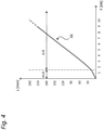
- the schematic diagram of 4 illustrates the effect of the bias of the spring tines 18, which already have a desired and required to avoid damage flexibility when hitting larger obstacles such as stones, lumps of earth or other such obstacles due to their resilient design and the annular spring 34.
- the spring tines 18 are each subjected to a defined and/or variably adjustable prestressing force within definable limits.
- the spring tines 18 are relaxed or not prestressed in a first, non-assembled state ( Figure 3B ), while the same spring tines 18 are prestressed in a second, assembled state and/or are subjected to a defined and/or variably adjustable prestressing force within definable limits ( Figure 3C ).
- Illustrated bias of the spring tines 18 allow a largely even tillage.
- the force-displacement diagram of the 4 indicates that the spring tines 18 give in to obstacles and deviate against the direction of travel by up to 200 mm or possibly a little more, which means that they can still provide sufficient spring travel when encountering obstacles such as stones.
- the spring tine 18 to which the pretensioning force is applied in the installed state has a non-linear force-displacement characteristic 56 .
- This non-linear force-displacement characteristic curve 56 which shows a relationship between a resistance force acting on the spring tines 18 or on its share tip 52 or 54 during a tillage operation and directed counter to the direction of travel 24, and a deflection, initially follows a zero point starting from a relatively flat course, which changes to a steeper course when the defined or definable preload force is reached.
- a force in kilo Newtons (F in kN) acting on the spring tines 18 is plotted on the horizontal abscissa, while the vertical ordinate shows the deflection caused thereby in millimeters (s in mm).
- the characteristic curve 56 describes a flatter course, since the pre-tension (mV in 4 ) acts, whereby the deflection at about 1.5 kN is only about 15 mm. Subsequently, the characteristic curve 56 has a point of discontinuity or a more or less clear kink in its course, which, depending on the design of the prestressing, may also be due to a rounded or softer transition or - depending on the design as a multi-stage prestressing - also due to multiple kinks, etc .can be replaced.
- the design of the annular spring 34, the radii of the arcuate area 46 and/or the height of the support element 40 and/or its prestressing force, both the curves of the force-displacement characteristic 56 and its gradient, the Placement of the transition area between the flatter course with prestressing and the steeper course without prestressing etc. can be adjusted and modified.
Landscapes
- Life Sciences & Earth Sciences (AREA)
- Engineering & Computer Science (AREA)
- Mechanical Engineering (AREA)
- Soil Sciences (AREA)
- Environmental Sciences (AREA)
- Soil Working Implements (AREA)
Claims (16)
- Appareil agricole de travail du sol (10), notamment cultivateur (12), doté d'un châssis (14) et de dents souples (18) qui y sont fixées, présentant chacune au moins une spire (36), caractérisé en ce qu'une force de précontrainte définie et/ou variable au sein de seuils définissables est appliquée à au moins une des dents souples (18) au moyen d'un élément d'application (40) qui fournit une surface d'appui à la dent souple (18), ladite dent souple (18) présentant une courbe caractéristique non linéaire du trajet de la force (56), ladite courbe caractéristique non linéaire du trajet de force présentant une trajectoire plate à partir du point zéro, et amorçant une pente à versant plus raide lorsqu'elle atteint une force de précontrainte définie ou pouvant être définie.
- Appareil agricole de travail du sol selon la revendication 1, dans lequel ladite au moins une dent souple (18) est détendue, voire non précontrainte dans un premier état ou elle n'est pas montée, et dans lequel la dent souple (18) est, dans un deuxième état où elle est montée, précontrainte et/ou à laquelle est appliquée une force de précontrainte définie et/ou variable au sein de seuils définissables et/ou ajustable de manière variable.
- Appareil agricole de travail du sol selon la revendication 1 ou 2, dans lequel l'élément d'application (40) est constitué d'un support en forme de clavette.
- Appareil agricole de travail du sol selon l'une quelconque des revendications 1 à 3, dans lequel l'élément d'application (40) est constitué au moins partiellement ou dans certaines portions d'un matériau souple et élastique.
- Appareil agricole de travail du sol selon l'une quelconque des revendications 1 à 4, dont au moins une dent souple (18), à laquelle est appliquée une force de précontrainte, présente une trajectoire en forme d'arc ou de faucille qui suit, dans certaines portions, notamment dans une zone à proximité du châssis (14), une trajectoire environ de même orientation, parallèle ou environ parallèle à une portion de serrage (30) fixée ou pouvant être fixée au ou dans le châssis (14), ladite au moins une spire (36) complète de la dent souple (18) décrivant un arc de cercle ou une portion d'arc de cercle d'un angle compris entre 500° et 600°.
- Appareil agricole de travail du sol selon la revendication 5, dans lequel la portion de serrage (30) de ladite au moins une dent souple (18) à laquelle est appliquée la force de précontrainte repose sur une face supérieure (21) ou inférieure d'un support de châssis (20) du châssis (14) et y est fixée ou peut y être fixée.
- Appareil agricole de travail du sol selon la revendication 5 ou 6, dans lequel ladite au moins une spire (36) de la dent souple (18) à laquelle est appliquée la force de précontrainte est agencée, dans le sens de marche (24) de l'appareil agricole de travail du sol (10) à l'avant du support du châssis (20), auquel la dent souple (18) est fixée ou peut être fixée.
- Appareil agricole de travail du sol selon l'une quelconque des revendications 5 à 7, dans lequel l'élément d'application (40) est agencé sur une face supérieure (21) ou inférieure du support de châssis (20), auquel la dent souple (18) est fixée ou peut être fixée, la portion de dos (46) de la dent souple (18) passant dans la trajectoire en forme d'arc ou de faucille et suivant au moins une spire repose sur l'élément d'application (40) définissant la force de précontrainte.
- Appareil agricole de travail du sol selon l'une quelconque des revendications 5 à 8, dans lequel l'élément d'application (40) comprend au moins une cavité, notamment pour accueillir et/ou pour coopérer avec des moyens de fixation.
- Appareil agricole de travail du sol selon l'une quelconque des revendications 5 à 9, dans lequel la surface d'appui de l'élément d'application (40) inclue le long de son sens d'étendue longitudinale un angle compris entre 5° et 11°.
- Dent souple (18) dotée d'au moins une spire (36), notamment destinée à être utilisée dans un appareil agricole de travail du sol (10) tel qu'un cultivateur (12) ou équivalent, notamment selon l'une quelconque des revendications 1 à 10, caractérisée en ce qu'une force de précontrainte définie et/ou variable au sein de seuils définissables est appliquée ou peut être appliquée à ladite dent souple (18), la dent souple (18) à laquelle est appliquée la force de précontrainte, étant précontrainte au moyen d'un élément d'application (40) qui fournit une surface d'appui à la dent souple (18), ladite dent souple (18) présentant une courbe caractéristique non linéaire du trajet de force (56), ladite courbe caractéristique non linéaire du trajet de force présentant une trajectoire plate à partir du point zéro et amorçant une pente à versant plus raide au moment où elle atteint une force de précontrainte définie ou pouvant être définie.
- Dent souple selon la revendication 11 qui est détendue ou non précontrainte dans un premier état, non montée à un châssis (14) et/ou pièce porteuse (20), notamment d'un appareil agricole de travail du sol (10), et qui, dans un deuxième état, montée à un châssis (14) et/ou à une pièce porteuse (20) est précontrainte et/ou à laquelle est appliquée ou peut être appliquée une force de précontrainte définie et/ou variable au sein de seuils définis.
- Dent souple selon la revendication 11 ou 12, souple et élastique, les caractéristiques élastiques de ladite au moins une dent souple (18) étant définies voire co-déterminées aussi bien par sa précontrainte que par la forme et/ou par l'épaisseur de matériau de la dent souple (18) et/ou par ses caractéristiques de matériau et/ou par sa solidarisation avec le châssis (14).
- Dent souple selon l'une quelconque des revendications 11 à 13, présentant une trajectoire en forme d'arc ou de faucille qui suit, dans certaines portions, notamment dans une zone à proximité d'une portion de serrage (30) pouvant être fixée au châssis (14) ou portion porteuse (20), une trajectoire environ de même orientation, parallèle ou environ parallèle à ladite portion de serrage (30), ladite au moins une spire (36) complète de la dent souple (18) décrivant un arc de cercle ou une portion d'arc de cercle d'un angle compris entre 500° et 600°.
- Assemblage d'une dent souple selon l'une quelconque des revendications 11 à 14, qui est montée à un châssis (14) ou une partie porteuse (20) d'un appareil agricole de travail du sol (10) selon l'une quelconque des revendications 1 à 10, notamment d'un cultivateur (12), caractérisé en ce que la dent souple (18) est précontrainte au moyen d'un élément d'application (40).
- Assemblage selon la revendication 15, dans lequel la portion de serrage (30) de ladite au moins une dent souple (18) à laquelle est appliquée la force de précontrainte repose sur une face supérieure (21) ou inférieure d'un support de châssis (20) du châssis (14) et y est fixée ou peut y être fixée.
Applications Claiming Priority (1)
| Application Number | Priority Date | Filing Date | Title |
|---|---|---|---|
| DE102016107951.0A DE102016107951A1 (de) | 2016-04-28 | 2016-04-28 | Landwirtschaftliches Bodenbearbeitungsgerät und Federzinken hierfür |
Publications (2)
| Publication Number | Publication Date |
|---|---|
| EP3245855A1 EP3245855A1 (fr) | 2017-11-22 |
| EP3245855B1 true EP3245855B1 (fr) | 2022-03-02 |
Family
ID=58266480
Family Applications (2)
| Application Number | Title | Priority Date | Filing Date |
|---|---|---|---|
| EP17160271.7A Active EP3248449B1 (fr) | 2016-04-28 | 2017-03-10 | Cultivateur, dents plates associées et système de dents plates sur un cultivateur |
| EP17160268.3A Active EP3245855B1 (fr) | 2016-04-28 | 2017-03-10 | Cultivateur, dents plates associées et système de dents plates |
Family Applications Before (1)
| Application Number | Title | Priority Date | Filing Date |
|---|---|---|---|
| EP17160271.7A Active EP3248449B1 (fr) | 2016-04-28 | 2017-03-10 | Cultivateur, dents plates associées et système de dents plates sur un cultivateur |
Country Status (2)
| Country | Link |
|---|---|
| EP (2) | EP3248449B1 (fr) |
| DE (1) | DE102016107951A1 (fr) |
Families Citing this family (7)
| Publication number | Priority date | Publication date | Assignee | Title |
|---|---|---|---|---|
| DE102017108135A1 (de) | 2017-04-13 | 2018-10-18 | Hartmut Böhner | Reiheneinheit zur mechanischen Unkrautbekämpfung, landwirtschaftliche Maschine mit zumindest zwei derartiger Reiheneinheiten und Verfahren zur mechanischen Unkrautbekämpfung |
| DE102017108119A1 (de) | 2017-04-13 | 2018-10-18 | Hartmut Böhner | Reiheneinheit zur mechanischen Unkrautbekämpfung, landwirtschaftliche Maschine mit zumindest zwei derartiger Reiheneinheiten und Verfahren zur mechanischen Unkrautbekämpfung |
| SE543476C2 (sv) * | 2018-06-08 | 2021-03-02 | Vaederstad Holding Ab | Infästningsanordning samt förfarande för löstagbar fixering av jordbearbetande verktyg, jordbearbetande verktyg, lantbruksredskap omfattande sådan infästningsanordning och jordbearbetande verktyg |
| DE202018106689U1 (de) * | 2018-11-23 | 2018-11-30 | Michael Popfinger | Bodenbearbeitungsmaschine |
| CN109892070B (zh) * | 2019-04-17 | 2023-09-05 | 中国科学院地理科学与资源研究所 | 一种适用于鹅卵石密集型地表层的开沟刀片 |
| AT16450U3 (de) * | 2019-05-16 | 2019-12-15 | Thomas Hatzenbichler Agro Technik Gmbh | Bodenbearbeitungsgerät |
| AT521778B1 (de) | 2019-05-16 | 2020-07-15 | Thomas Hatzenbichler Agro Technik Gmbh | Bodenbearbeitungsgerät |
Citations (2)
| Publication number | Priority date | Publication date | Assignee | Title |
|---|---|---|---|---|
| DE3346396A1 (de) * | 1983-12-22 | 1985-07-11 | Federnwerke Paul Plate GmbH, 5800 Hagen | Loesbare befestigungsvorrichtung fuer federzinken |
| CA2928289A1 (fr) * | 2013-10-21 | 2015-04-30 | Suhua LIU | Procede de deplacement et de reajustement des dents de herse d'une excavatrice a herse et excavatrice a herse dont les dents peuvent etre dirigees et reajustees pour la mise en oeuvre du procede |
Family Cites Families (14)
| Publication number | Priority date | Publication date | Assignee | Title |
|---|---|---|---|---|
| DE247207C (fr) * | ||||
| US1768289A (en) * | 1930-06-24 | Machine fob killing qttacx gbass | ||
| US3710872A (en) * | 1970-08-11 | 1973-01-16 | Kovar J Mfg Co Inc | Ground engaging implement tooth and mounting means therefor |
| DK143191C (da) * | 1972-12-13 | 1981-12-14 | Kongskilde Maskinfabrik As | Stubharvetand |
| FR2418612A1 (fr) * | 1978-03-02 | 1979-09-28 | Mecanique Gle Minotoise | Outil agricole tel que herse |
| DE10207020A1 (de) | 2002-02-20 | 2003-08-28 | Amazonen Werke Dreyer H | Grubber |
| DE10238917A1 (de) | 2002-02-20 | 2004-03-04 | Amazonen-Werke H. Dreyer Gmbh & Co. Kg | Grubber |
| DE20213736U1 (de) | 2002-09-03 | 2002-12-05 | Hendlmeier Konrad | Überlastsicherung für landwirtschaftliche Maschinen |
| DE10341757B4 (de) | 2003-09-10 | 2006-11-02 | Landmaschinenfabrik Köckerling GmbH & Co KG | Landwirtschaftliche Maschine |
| DE102007008616A1 (de) | 2007-02-22 | 2008-08-28 | Paul Treffler | Elektronische Zinkendruckverstelleinheit |
| SE0900819A1 (sv) | 2009-06-16 | 2010-06-01 | Vaederstad Verken Ab | Kultivator med fram- och bakåtvända jordbearbetande verktyg på samma balk |
| DE102009051431A1 (de) * | 2009-10-30 | 2011-05-19 | LAMATOR GmbH Landwirtschaftliche Maschinenausrüstungen | Anordnung für Bodenbearbeitungswerkzeuge und deren Verwendung |
| DE102012005027A1 (de) * | 2012-03-12 | 2013-09-12 | Köckerling GmbH & Co. KG | Bodenbearbeitungsgerät und Federzinkenlagerelement |
| EP2923538B1 (fr) * | 2014-03-24 | 2020-09-30 | BIANCHI S.r.l. | Structure de verrouillage pour machines agricoles |
-
2016
- 2016-04-28 DE DE102016107951.0A patent/DE102016107951A1/de active Pending
-
2017
- 2017-03-10 EP EP17160271.7A patent/EP3248449B1/fr active Active
- 2017-03-10 EP EP17160268.3A patent/EP3245855B1/fr active Active
Patent Citations (2)
| Publication number | Priority date | Publication date | Assignee | Title |
|---|---|---|---|---|
| DE3346396A1 (de) * | 1983-12-22 | 1985-07-11 | Federnwerke Paul Plate GmbH, 5800 Hagen | Loesbare befestigungsvorrichtung fuer federzinken |
| CA2928289A1 (fr) * | 2013-10-21 | 2015-04-30 | Suhua LIU | Procede de deplacement et de reajustement des dents de herse d'une excavatrice a herse et excavatrice a herse dont les dents peuvent etre dirigees et reajustees pour la mise en oeuvre du procede |
Also Published As
| Publication number | Publication date |
|---|---|
| EP3248449B1 (fr) | 2023-05-31 |
| EP3245855A1 (fr) | 2017-11-22 |
| EP3248449A1 (fr) | 2017-11-29 |
| DE102016107951A1 (de) | 2017-11-02 |
Similar Documents
| Publication | Publication Date | Title |
|---|---|---|
| EP3245855B1 (fr) | Cultivateur, dents plates associées et système de dents plates | |
| DE60037458T3 (de) | Landwirtschaftliches Gerät | |
| EP1951024B1 (fr) | Appareil de traitement du sol dote d'une protection de manivelle | |
| EP3387890A1 (fr) | Unité de travail sur la ligne destinée au désherbage mécanique, engin agricole pourvu d'au moins deux unités de travail sur la ligne ainsi que procédé de désherbage mécanique | |
| EP3753386A1 (fr) | Dispositif de précontrainte et dispositif de traitement du sol agricole | |
| EP3556192B1 (fr) | Machine agricole de traitement du sol ainsi que procédé de traitement du sol | |
| EP1964459B1 (fr) | Machine à semer | |
| EP0081742A1 (fr) | Appareil à travailler la terre déplaçable sur un champ | |
| DE2725233A1 (de) | Biegsame befestigungsvorrichtung fuer das seitliche leitblech von bodenbearbeitungsmaschinen | |
| DE102012005027A1 (de) | Bodenbearbeitungsgerät und Federzinkenlagerelement | |
| EP3597022A1 (fr) | Machine agricole de traitement du sol ainsi que procédé de traitement du sol | |
| EP3226673A1 (fr) | Système de réglage de l'age d'un outil de travail du sol | |
| EP3707978B1 (fr) | Machine de traitement du sol et procédé de traitement du sol | |
| DE102009051431A1 (de) | Anordnung für Bodenbearbeitungswerkzeuge und deren Verwendung | |
| DE102016111773B4 (de) | Landwirtschaftliches Bodenbearbeitungsgerät mit Bodenbearbeitungswerkzeugen und Befestigungsanordnung für ein Bodenbearbeitungswerkzeug | |
| DE102022113040B3 (de) | Bodenbearbeitungsgerät | |
| EP3481169B1 (fr) | Engin de travail du sol pourvu d'un dispositif de sécurité | |
| DE4015326C1 (fr) | ||
| WO2023179821A1 (fr) | Appareil de travail du sol | |
| DE1164727B (de) | Aus mehreren Teilen zusammengesetzter Kultivator-Zinken | |
| DE2554352C3 (de) | Räumvorrichtung, insbesondere zum Räumen abgeholzter Forstflächen | |
| DE102021117388A1 (de) | Bodenbearbeitungsvorrichtung | |
| EP4173457A1 (fr) | Agencement doté d'un outil de travail destiné au traitement du sol pour une machine agricole, ainsi que machine agricole | |
| DE202017106019U1 (de) | Schwer-Striegel für Bodenbearbeitungsgeräte | |
| DE202009014661U1 (de) | Anordnung für Bodenbearbeitungswerkzeuge |
Legal Events
| Date | Code | Title | Description |
|---|---|---|---|
| PUAI | Public reference made under article 153(3) epc to a published international application that has entered the european phase |
Free format text: ORIGINAL CODE: 0009012 |
|
| STAA | Information on the status of an ep patent application or granted ep patent |
Free format text: STATUS: THE APPLICATION HAS BEEN PUBLISHED |
|
| AK | Designated contracting states |
Kind code of ref document: A1 Designated state(s): AL AT BE BG CH CY CZ DE DK EE ES FI FR GB GR HR HU IE IS IT LI LT LU LV MC MK MT NL NO PL PT RO RS SE SI SK SM TR |
|
| AX | Request for extension of the european patent |
Extension state: BA ME |
|
| STAA | Information on the status of an ep patent application or granted ep patent |
Free format text: STATUS: REQUEST FOR EXAMINATION WAS MADE |
|
| 17P | Request for examination filed |
Effective date: 20180321 |
|
| RBV | Designated contracting states (corrected) |
Designated state(s): AL AT BE BG CH CY CZ DE DK EE ES FI FR GB GR HR HU IE IS IT LI LT LU LV MC MK MT NL NO PL PT RO RS SE SI SK SM TR |
|
| STAA | Information on the status of an ep patent application or granted ep patent |
Free format text: STATUS: EXAMINATION IS IN PROGRESS |
|
| 17Q | First examination report despatched |
Effective date: 20210324 |
|
| GRAP | Despatch of communication of intention to grant a patent |
Free format text: ORIGINAL CODE: EPIDOSNIGR1 |
|
| STAA | Information on the status of an ep patent application or granted ep patent |
Free format text: STATUS: GRANT OF PATENT IS INTENDED |
|
| INTG | Intention to grant announced |
Effective date: 20211013 |
|
| GRAS | Grant fee paid |
Free format text: ORIGINAL CODE: EPIDOSNIGR3 |
|
| GRAA | (expected) grant |
Free format text: ORIGINAL CODE: 0009210 |
|
| STAA | Information on the status of an ep patent application or granted ep patent |
Free format text: STATUS: THE PATENT HAS BEEN GRANTED |
|
| AK | Designated contracting states |
Kind code of ref document: B1 Designated state(s): AL AT BE BG CH CY CZ DE DK EE ES FI FR GB GR HR HU IE IS IT LI LT LU LV MC MK MT NL NO PL PT RO RS SE SI SK SM TR |
|
| REG | Reference to a national code |
Ref country code: GB Ref legal event code: FG4D Free format text: NOT ENGLISH |
|
| REG | Reference to a national code |
Ref country code: CH Ref legal event code: EP Ref country code: AT Ref legal event code: REF Ref document number: 1471490 Country of ref document: AT Kind code of ref document: T Effective date: 20220315 |
|
| REG | Reference to a national code |
Ref country code: DE Ref legal event code: R096 Ref document number: 502017012667 Country of ref document: DE |
|
| REG | Reference to a national code |
Ref country code: IE Ref legal event code: FG4D Free format text: LANGUAGE OF EP DOCUMENT: GERMAN |
|
| REG | Reference to a national code |
Ref country code: LT Ref legal event code: MG9D |
|
| REG | Reference to a national code |
Ref country code: NL Ref legal event code: MP Effective date: 20220302 |
|
| PG25 | Lapsed in a contracting state [announced via postgrant information from national office to epo] |
Ref country code: SE Free format text: LAPSE BECAUSE OF FAILURE TO SUBMIT A TRANSLATION OF THE DESCRIPTION OR TO PAY THE FEE WITHIN THE PRESCRIBED TIME-LIMIT Effective date: 20220302 Ref country code: RS Free format text: LAPSE BECAUSE OF FAILURE TO SUBMIT A TRANSLATION OF THE DESCRIPTION OR TO PAY THE FEE WITHIN THE PRESCRIBED TIME-LIMIT Effective date: 20220302 Ref country code: NO Free format text: LAPSE BECAUSE OF FAILURE TO SUBMIT A TRANSLATION OF THE DESCRIPTION OR TO PAY THE FEE WITHIN THE PRESCRIBED TIME-LIMIT Effective date: 20220602 Ref country code: LT Free format text: LAPSE BECAUSE OF FAILURE TO SUBMIT A TRANSLATION OF THE DESCRIPTION OR TO PAY THE FEE WITHIN THE PRESCRIBED TIME-LIMIT Effective date: 20220302 Ref country code: HR Free format text: LAPSE BECAUSE OF FAILURE TO SUBMIT A TRANSLATION OF THE DESCRIPTION OR TO PAY THE FEE WITHIN THE PRESCRIBED TIME-LIMIT Effective date: 20220302 Ref country code: ES Free format text: LAPSE BECAUSE OF FAILURE TO SUBMIT A TRANSLATION OF THE DESCRIPTION OR TO PAY THE FEE WITHIN THE PRESCRIBED TIME-LIMIT Effective date: 20220302 Ref country code: BG Free format text: LAPSE BECAUSE OF FAILURE TO SUBMIT A TRANSLATION OF THE DESCRIPTION OR TO PAY THE FEE WITHIN THE PRESCRIBED TIME-LIMIT Effective date: 20220602 |
|
| PG25 | Lapsed in a contracting state [announced via postgrant information from national office to epo] |
Ref country code: PL Free format text: LAPSE BECAUSE OF FAILURE TO SUBMIT A TRANSLATION OF THE DESCRIPTION OR TO PAY THE FEE WITHIN THE PRESCRIBED TIME-LIMIT Effective date: 20220302 Ref country code: LV Free format text: LAPSE BECAUSE OF FAILURE TO SUBMIT A TRANSLATION OF THE DESCRIPTION OR TO PAY THE FEE WITHIN THE PRESCRIBED TIME-LIMIT Effective date: 20220302 Ref country code: GR Free format text: LAPSE BECAUSE OF FAILURE TO SUBMIT A TRANSLATION OF THE DESCRIPTION OR TO PAY THE FEE WITHIN THE PRESCRIBED TIME-LIMIT Effective date: 20220603 Ref country code: FI Free format text: LAPSE BECAUSE OF FAILURE TO SUBMIT A TRANSLATION OF THE DESCRIPTION OR TO PAY THE FEE WITHIN THE PRESCRIBED TIME-LIMIT Effective date: 20220302 |
|
| PG25 | Lapsed in a contracting state [announced via postgrant information from national office to epo] |
Ref country code: NL Free format text: LAPSE BECAUSE OF FAILURE TO SUBMIT A TRANSLATION OF THE DESCRIPTION OR TO PAY THE FEE WITHIN THE PRESCRIBED TIME-LIMIT Effective date: 20220302 |
|
| PG25 | Lapsed in a contracting state [announced via postgrant information from national office to epo] |
Ref country code: SM Free format text: LAPSE BECAUSE OF FAILURE TO SUBMIT A TRANSLATION OF THE DESCRIPTION OR TO PAY THE FEE WITHIN THE PRESCRIBED TIME-LIMIT Effective date: 20220302 Ref country code: SK Free format text: LAPSE BECAUSE OF FAILURE TO SUBMIT A TRANSLATION OF THE DESCRIPTION OR TO PAY THE FEE WITHIN THE PRESCRIBED TIME-LIMIT Effective date: 20220302 Ref country code: RO Free format text: LAPSE BECAUSE OF FAILURE TO SUBMIT A TRANSLATION OF THE DESCRIPTION OR TO PAY THE FEE WITHIN THE PRESCRIBED TIME-LIMIT Effective date: 20220302 Ref country code: PT Free format text: LAPSE BECAUSE OF FAILURE TO SUBMIT A TRANSLATION OF THE DESCRIPTION OR TO PAY THE FEE WITHIN THE PRESCRIBED TIME-LIMIT Effective date: 20220704 Ref country code: EE Free format text: LAPSE BECAUSE OF FAILURE TO SUBMIT A TRANSLATION OF THE DESCRIPTION OR TO PAY THE FEE WITHIN THE PRESCRIBED TIME-LIMIT Effective date: 20220302 Ref country code: CZ Free format text: LAPSE BECAUSE OF FAILURE TO SUBMIT A TRANSLATION OF THE DESCRIPTION OR TO PAY THE FEE WITHIN THE PRESCRIBED TIME-LIMIT Effective date: 20220302 |
|
| REG | Reference to a national code |
Ref country code: CH Ref legal event code: PL |
|
| PG25 | Lapsed in a contracting state [announced via postgrant information from national office to epo] |
Ref country code: IS Free format text: LAPSE BECAUSE OF FAILURE TO SUBMIT A TRANSLATION OF THE DESCRIPTION OR TO PAY THE FEE WITHIN THE PRESCRIBED TIME-LIMIT Effective date: 20220702 Ref country code: AL Free format text: LAPSE BECAUSE OF FAILURE TO SUBMIT A TRANSLATION OF THE DESCRIPTION OR TO PAY THE FEE WITHIN THE PRESCRIBED TIME-LIMIT Effective date: 20220302 |
|
| REG | Reference to a national code |
Ref country code: DE Ref legal event code: R097 Ref document number: 502017012667 Country of ref document: DE |
|
| REG | Reference to a national code |
Ref country code: BE Ref legal event code: MM Effective date: 20220331 |
|
| PLBE | No opposition filed within time limit |
Free format text: ORIGINAL CODE: 0009261 |
|
| STAA | Information on the status of an ep patent application or granted ep patent |
Free format text: STATUS: NO OPPOSITION FILED WITHIN TIME LIMIT |
|
| PG25 | Lapsed in a contracting state [announced via postgrant information from national office to epo] |
Ref country code: MC Free format text: LAPSE BECAUSE OF FAILURE TO SUBMIT A TRANSLATION OF THE DESCRIPTION OR TO PAY THE FEE WITHIN THE PRESCRIBED TIME-LIMIT Effective date: 20220302 Ref country code: LU Free format text: LAPSE BECAUSE OF NON-PAYMENT OF DUE FEES Effective date: 20220310 Ref country code: LI Free format text: LAPSE BECAUSE OF NON-PAYMENT OF DUE FEES Effective date: 20220331 Ref country code: IE Free format text: LAPSE BECAUSE OF NON-PAYMENT OF DUE FEES Effective date: 20220310 Ref country code: FR Free format text: LAPSE BECAUSE OF NON-PAYMENT OF DUE FEES Effective date: 20220502 Ref country code: DK Free format text: LAPSE BECAUSE OF FAILURE TO SUBMIT A TRANSLATION OF THE DESCRIPTION OR TO PAY THE FEE WITHIN THE PRESCRIBED TIME-LIMIT Effective date: 20220302 Ref country code: CH Free format text: LAPSE BECAUSE OF NON-PAYMENT OF DUE FEES Effective date: 20220331 |
|
| 26N | No opposition filed |
Effective date: 20221205 |
|
| PG25 | Lapsed in a contracting state [announced via postgrant information from national office to epo] |
Ref country code: SI Free format text: LAPSE BECAUSE OF FAILURE TO SUBMIT A TRANSLATION OF THE DESCRIPTION OR TO PAY THE FEE WITHIN THE PRESCRIBED TIME-LIMIT Effective date: 20220302 Ref country code: BE Free format text: LAPSE BECAUSE OF NON-PAYMENT OF DUE FEES Effective date: 20220331 |
|
| GBPC | Gb: european patent ceased through non-payment of renewal fee |
Effective date: 20220602 |
|
| REG | Reference to a national code |
Ref country code: AT Ref legal event code: MM01 Ref document number: 1471490 Country of ref document: AT Kind code of ref document: T Effective date: 20220310 |
|
| PG25 | Lapsed in a contracting state [announced via postgrant information from national office to epo] |
Ref country code: GB Free format text: LAPSE BECAUSE OF NON-PAYMENT OF DUE FEES Effective date: 20220602 |
|
| PG25 | Lapsed in a contracting state [announced via postgrant information from national office to epo] |
Ref country code: IT Free format text: LAPSE BECAUSE OF FAILURE TO SUBMIT A TRANSLATION OF THE DESCRIPTION OR TO PAY THE FEE WITHIN THE PRESCRIBED TIME-LIMIT Effective date: 20220302 Ref country code: AT Free format text: LAPSE BECAUSE OF NON-PAYMENT OF DUE FEES Effective date: 20220310 |
|
| PG25 | Lapsed in a contracting state [announced via postgrant information from national office to epo] |
Ref country code: HU Free format text: LAPSE BECAUSE OF FAILURE TO SUBMIT A TRANSLATION OF THE DESCRIPTION OR TO PAY THE FEE WITHIN THE PRESCRIBED TIME-LIMIT; INVALID AB INITIO Effective date: 20170310 |
|
| PG25 | Lapsed in a contracting state [announced via postgrant information from national office to epo] |
Ref country code: MK Free format text: LAPSE BECAUSE OF FAILURE TO SUBMIT A TRANSLATION OF THE DESCRIPTION OR TO PAY THE FEE WITHIN THE PRESCRIBED TIME-LIMIT Effective date: 20220302 Ref country code: CY Free format text: LAPSE BECAUSE OF FAILURE TO SUBMIT A TRANSLATION OF THE DESCRIPTION OR TO PAY THE FEE WITHIN THE PRESCRIBED TIME-LIMIT Effective date: 20220302 |
|
| PGFP | Annual fee paid to national office [announced via postgrant information from national office to epo] |
Ref country code: DE Payment date: 20240321 Year of fee payment: 8 |