EP3245655B1 - Systeme de ventilation d'un local professionel et procede pour l'usage pendant un accident grave dans une installation nucleaire - Google Patents
Systeme de ventilation d'un local professionel et procede pour l'usage pendant un accident grave dans une installation nucleaire Download PDFInfo
- Publication number
- EP3245655B1 EP3245655B1 EP16701571.8A EP16701571A EP3245655B1 EP 3245655 B1 EP3245655 B1 EP 3245655B1 EP 16701571 A EP16701571 A EP 16701571A EP 3245655 B1 EP3245655 B1 EP 3245655B1
- Authority
- EP
- European Patent Office
- Prior art keywords
- air
- fan
- inert gas
- ventilation system
- gas adsorber
- Prior art date
- Legal status (The legal status is an assumption and is not a legal conclusion. Google has not performed a legal analysis and makes no representation as to the accuracy of the status listed.)
- Active
Links
Images

Classifications
-
- B—PERFORMING OPERATIONS; TRANSPORTING
- B01—PHYSICAL OR CHEMICAL PROCESSES OR APPARATUS IN GENERAL
- B01D—SEPARATION
- B01D53/00—Separation of gases or vapours; Recovering vapours of volatile solvents from gases; Chemical or biological purification of waste gases, e.g. engine exhaust gases, smoke, fumes, flue gases, aerosols
- B01D53/02—Separation of gases or vapours; Recovering vapours of volatile solvents from gases; Chemical or biological purification of waste gases, e.g. engine exhaust gases, smoke, fumes, flue gases, aerosols by adsorption, e.g. preparative gas chromatography
- B01D53/04—Separation of gases or vapours; Recovering vapours of volatile solvents from gases; Chemical or biological purification of waste gases, e.g. engine exhaust gases, smoke, fumes, flue gases, aerosols by adsorption, e.g. preparative gas chromatography with stationary adsorbents
- B01D53/0407—Constructional details of adsorbing systems
- B01D53/0446—Means for feeding or distributing gases
-
- G—PHYSICS
- G21—NUCLEAR PHYSICS; NUCLEAR ENGINEERING
- G21D—NUCLEAR POWER PLANT
- G21D1/00—Details of nuclear power plant
- G21D1/02—Arrangements of auxiliary equipment
-
- G—PHYSICS
- G21—NUCLEAR PHYSICS; NUCLEAR ENGINEERING
- G21D—NUCLEAR POWER PLANT
- G21D3/00—Control of nuclear power plant
- G21D3/04—Safety arrangements
- G21D3/06—Safety arrangements responsive to faults within the plant
-
- G—PHYSICS
- G21—NUCLEAR PHYSICS; NUCLEAR ENGINEERING
- G21F—PROTECTION AGAINST X-RADIATION, GAMMA RADIATION, CORPUSCULAR RADIATION OR PARTICLE BOMBARDMENT; TREATING RADIOACTIVELY CONTAMINATED MATERIAL; DECONTAMINATION ARRANGEMENTS THEREFOR
- G21F7/00—Shielded cells or rooms
- G21F7/015—Room atmosphere, temperature or pressure control devices
-
- G—PHYSICS
- G21—NUCLEAR PHYSICS; NUCLEAR ENGINEERING
- G21F—PROTECTION AGAINST X-RADIATION, GAMMA RADIATION, CORPUSCULAR RADIATION OR PARTICLE BOMBARDMENT; TREATING RADIOACTIVELY CONTAMINATED MATERIAL; DECONTAMINATION ARRANGEMENTS THEREFOR
- G21F9/00—Treating radioactively contaminated material; Decontamination arrangements therefor
- G21F9/02—Treating gases
-
- B—PERFORMING OPERATIONS; TRANSPORTING
- B01—PHYSICAL OR CHEMICAL PROCESSES OR APPARATUS IN GENERAL
- B01D—SEPARATION
- B01D2257/00—Components to be removed
- B01D2257/10—Single element gases other than halogens
-
- Y—GENERAL TAGGING OF NEW TECHNOLOGICAL DEVELOPMENTS; GENERAL TAGGING OF CROSS-SECTIONAL TECHNOLOGIES SPANNING OVER SEVERAL SECTIONS OF THE IPC; TECHNICAL SUBJECTS COVERED BY FORMER USPC CROSS-REFERENCE ART COLLECTIONS [XRACs] AND DIGESTS
- Y02—TECHNOLOGIES OR APPLICATIONS FOR MITIGATION OR ADAPTATION AGAINST CLIMATE CHANGE
- Y02E—REDUCTION OF GREENHOUSE GAS [GHG] EMISSIONS, RELATED TO ENERGY GENERATION, TRANSMISSION OR DISTRIBUTION
- Y02E30/00—Energy generation of nuclear origin
- Y02E30/30—Nuclear fission reactors
Definitions
- a massive noble gas release may also occur when a filtered pressure relief is initiated and a noble gas cloud forms over the power plant site. Depending on the weather, long-term exposure cannot be completely ruled out.
- control room also known as the control room or control room
- the conditions in the control room allow operating personnel to stay without inadmissible radiation exposure and contamination of the personnel.
- the invention is based on the object of specifying a ventilation system, kept as simple and compact as possible, for a control room of a nuclear facility or a similar room accessible by operating personnel, which in the event of severe incidents with the release of radioactive activity, a supply of decontaminated fresh air for at least a few hours so that there is as little radiation exposure as possible to the operating staff present in the control room.
- the proportion of radioactive noble gases in the fresh air supplied to the control room should be as low as possible.
- the ventilation system should also be as passive as possible and consume little electrical energy. Furthermore, a particularly advantageous method for operating such a ventilation system is to be specified.
- the object is achieved according to the invention by the features of claim 1.
- the object is achieved by the features of claim 11.
- the ventilation system according to the invention advantageously has, inter alia, an aerosol and iodine filter module.
- the intake air in the supply air line is here Sucked in by a fan and fed through a particulate filter to separate the aerosols.
- radioactive iodine compounds are advantageously separated out in an activated carbon filter bed.
- Impregnated activated carbon can be used to separate the radioactive methyl iodide through isotope exchange or salt formation.
- a particle filter is advantageously connected downstream of the activated carbon bed in order to retain abrasion.
- the air filtered in this way is then fed to a noble gas module in a second process step.
- the noble gas module essentially contains two adsorber columns in a twin configuration, which are filled with adsorbent / adsorbents, preferably activated carbon.
- the adsorbent of the columns can also be built up from several layers of activated carbon and / or zeolite and / or molecular sieves.
- the supply air enters the first adsorber column, the noble gases such. B. Xenon, krypton are delayed by dynamic adsorption as they pass through the column.
- a filter for retaining adsorber particles is expediently arranged.
- the exhaust air from the area of the room to be supplied is simultaneously led over the second adsorber column and there causes the previously accumulated noble gas activity to be backwashed so that this column is ready for loading again after the switchover.
- the switchover is carried out at the latest shortly before the breakthrough of activity in the first adsorber column, which is then backwashed with the exhaust air.
- the switchover is preferably triggered passively by a timer or an activity measurement.
- the backwashing is advantageously supported by a fan in the exhaust air line, the increase in volume of the exhaust air flow due to the negative pressure intensifying the backwashing process of the noble gases.
- a throttle which is used to passively overheat the exhaust air and thus to reduce the amount in the exhaust air moisture (expansion drying). This promotes the desorption speed of the noble gases in the downstream adsorber column to be purged.
- a throttle and / or an air dryer are advantageously located in the supply air line to the noble gas module in order to prevent excessive moisture from being conveyed to the noble gas columns.
- the noble gas module can also be equipped with a passive cooling store to increase the k values.
- the k value describes the adsorption capacity of the adsorber material for noble gas in e.g. B. the unit cm 3 noble gas / g adsorbent.
- the k-value depends on the temperature, pressure and moisture content of the gas. It is usually determined empirically.
- the adsorber columns are preferably operated in the pressure swing process, d. H. Underpressure of the column to be flushed and overpressure of the column to be loaded (each in relation to atmospheric pressure) in order to improve the k values of the columns and reduce their dimensions.
- the overpressure in the adsorber column through which the supply air flows is regulated, for example, with an adjusting valve in the supply air line.
- the exhaust air is released together with the back-flushed noble gases into the power plant environment at a sufficient distance from the supply air intake.
- the ventilation system expediently comprises a control system and corresponding adjusting elements for flow and pressures.
- the advantages achieved with the invention are in particular that, in addition to the airborne activities in the form of aerosols and iodine / iodine compounds (especially organoiodine), the radioactive noble gases are also retained from the air supply to the control room.
- the pressure change and flushing process of the twin columns even long-lived noble gas isotopes such as krypton-85 can be reliably separated from the supply air flow.
- the one to remove the noble gases Conditions required by the sorbent / adsorbent are passively supported by expansion superheating.
- a self-sufficient energy supply module e.g. with batteries and / or a diesel generator
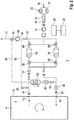
- FIG. 1 gives a schematic and greatly simplified overview of a ventilation system for a control room of a nuclear power plant in the manner of a block flow diagram.
- FIG. 2 shows a modification (extension) of the in FIG. 1 illustrated system.
- the accident ventilation system shown, or ventilation system 2 for short is used to supply fresh air to a control room 4 of a nuclear power plant 6, also known as the control room or in English as the Main Control Room (MCR), in accident or incident situations, especially in the initial phase of a serious incident with the release of nuclear fission products within of the power plant building and, if necessary, in the vicinity.
- MCR Main Control Room
- the ventilation system 2 for the control room 4 is designed on the one hand for a supply of decontaminated and oxygen-rich fresh air - also called supply air - from the surroundings of the control room 4 or the power plant building and is equipped with appropriate filter and cleaning stages.
- the ventilation system 2 effects a removal of used and carbon dioxide-rich air - also called exhaust air - from the control station 4 into the environment.
- there is neither a fresh air supply from an associated compressed air storage system A significant recirculation and reprocessing of the air in the interior of the control station 4 is also provided.
- a supply air line 10 also referred to as a fresh air supply line or fresh air line for short, is connected to the at least approximately hermetically sealed interior 8 of the control center 4, through which fresh air is sucked in from the environment with the help of a fan 12 and into the air supply during operation of the ventilation system 2 Interior 8 is promoted.
- the intake inlet or, for short, inlet 14 of the air supply line 10 can be some distance from the control station 4, in particular outside the power station building.
- the fresh air sucked in via inlet 14 can nevertheless be considerably contaminated with radioactive fission products, in particular in the form of aerosols, iodine and iodine compounds and noble gases.
- These components should be removed as completely and reliably as possible from the fresh air flow - also known as the supply air flow - before it is introduced into the interior space 8 of the control room 4 through a passage 16 in the surrounding wall 18 (only shown partially).
- the HEPA filters 22 accordingly effect a highly efficient separation of the aerosol particles, also referred to as floating particles, from the fresh air flow, in particular with regard to the isotopes Te, Cs, Ba, Ru, Ce, La.
- a second filter stage with an iodine filter 24 and a downstream particle filter 26 is connected into the supply air line 10.
- the iodine filter 24 is preferably implemented in the form of an activated carbon filter bed with a layer thickness of 0.1 to 0.5 m, for example.
- radioactive iodine compounds and elemental iodine are formed in the iodine filter 24 during contact times deposited from 0.1 to 0.5 s.
- Impregnated activated carbon e.g. with potassium iodide as an impregnating agent
- the particle filter 26 connected downstream of the iodine filter 24 is provided to hold back abrasion from the activated carbon bed.
- the fan 12 Connected downstream of the second filter stage is a conveying fan or, for short, a fan 12 for transporting the fresh air flow into the supply air line 10.
- the fan 12 which is preferably electrically driven, has a suction capacity in the range of, for example, 100 to 6,000 m 3 / h.
- a self-sufficient power supply module 28 which is independent of the normal internal power supply and preferably also of the usual (plant-wide) emergency power network, is provided, for example on the basis of electric batteries / accumulators and / or a diesel unit.
- the power supply module 28 is preferably activated independently in the manner of an uninterruptible power supply or, alternatively, is controlled via an assigned control unit 30.
- an air dryer 32 also referred to as a cold trap, is optionally connected into the supply air line 10, with which condensable components can be separated from the fresh air flow.
- it can be a passive cold trap with silica gel and / or ice as the drying agent. This reduces the moisture content of the fresh air stream flowing into the downstream functional units (see below).
- the same purpose is served by an alternatively or additionally present, here in the exemplary embodiment, arranged behind the air dryer 32 in the flow direction of the fresh air, arranged throttle 34 which acts on the fresh air flow according to the principle of expansion drying. It can in particular be a controllable throttle valve.
- the fresh air stream flows through the line section 36, for example, into which a noble gas adsorber column or adsorber column 38 is connected if the associated actuating elements are in the appropriate position (see below).
- the noble gases contained in the fresh air flow especially xenon and krypton, are bound by physical and / or chemical adsorption to the adsorbent present in the adsorber column 38 within the scope of a dynamically established equilibrium and thus delayed in the line section 36 as long as the adsorption capacity of the adsorber column 38 is not yet exhausted.
- one or more layers of activated carbon and / or zeolite and / or molecular sieves can be provided as the adsorbent.
- the adsorber column 38 is followed by a line section leading to the control station 4, into which a particle filter 40 is connected to retain detached adsorber particles.
- the fresh air stream decontaminated in the manner described enters the interior 8 via the duct 16 through the surrounding wall 18 of the control station 4, so that unused, oxygen-rich breathing air is supplied to it with an activity level permissible for the operating personnel.
- the exchange of air is completed by the removal of used, carbon dioxide-rich breathing air from the control room 4 via the exhaust air line 44 connected to its interior 8 and led through the duct 42 in the surrounding wall 18 into the environment, into which a fan 46 is connected to support the gas transport .
- This is preferably an electrically driven blower 46, which, like the blower 12, is supplied with electrical power via the power supply module 28.
- the ventilation system 2 is designed for backwashing the adsorbed noble gases into the environment during operation.
- adsorber columns 38 and 48 which are supplied with fresh air or exhaust air via corresponding line branches and connections as well as actuators, here in the form of 3-way valves, in such a way that one of the two adsorber columns 38 and 48 like already described, acts on the fresh air flow in adsorption operation, while the other is backwashed by the exhaust air flow at the same time in desorption operation or flushing operation and thus made ready for the next adsorption cycle.
- the role of the adsorber columns 38 and 48 can be interchanged and thus cyclically changed between adsorption operation and desorption operation with respect to the respective column.
- this functionality is implemented in that one adsorber column 38 is arranged in the line section 36, and the other adsorber column 48 in flow-wise anti-parallel connection in the line section 50.
- Both line sections 36 and 50 unite on one side in the 3-way valve 52 and on the other side in the union 54 arranged on the suction side of the blower 46.
- switchable cross-connection 60 connected between the two line sections 36 and 50, which is connected via a T connection 62 to the section of the air supply line 10 leading to the particle filter 40.
- a cross-connection 68 that can be switched by the two 3-way valves 64 and 66 is connected, which via a T connection 70 with the section coming from the throttle 34 the supply air line 10 is connected.
- the supply air coming from the throttle 34 flows through the T connection 70, the 3-way valve 66, the adsorber column 38, the 3-way valve 58 and the T, which is lower in the figure -Connection 62 to the particle filter 40 and from there to the control station 4.
- the exhaust air coming from the control station 4 flows through the 3-way valve 52, the 3-way valve 56, the adsorber column at the top in the figure 48 and the 3-way valve 64 to the suction connection of the blower 46 and from there on to an exhaust air chimney or to another outlet 72, which is expediently at some distance from the inlet 14 for fresh air.
- the noble gases accumulated by adsorption in the adsorber column 48 in the previous cycle are desorbed from the adsorbent by the largely noble gas-free exhaust air from the interior 8 of the control station 4 in this operating mode and flushed back into the environment with the exhaust air flow.
- the backwashing is supported by the fan 46 arranged downstream of the backwashed adsorber column 48, the increase in volume of the exhaust air flow due to the negative pressure intensifying the backwashing process of the noble gases.
- a throttle 74 preferably in the form of an adjustable throttle valve, which is used for passive overheating of the exhaust air and is seen in the direction of the exhaust air flow this leads to a reduction in the moisture in the exhaust air (expansion drying). This promotes the desorption speed of the noble gases in the downstream adsorber column 48.
- the fresh air now flows from the throttle 34 via the 3-way valve 64, the adsorber column 48 and the 3-way valve 56 to the particle filter 40 and from there to the control room 4.
- the exhaust air from the control room 4 flows from the throttle 74 via the 3-way valve 52, the 3-way valve 58, the adsorber column 38 and the 3-way valve 66 to the fan 46 and from there to the Outlet 72.
- the previously loaded adsorber column 38 is now backwashed by the exhaust air, while the adsorber column 48 is available for cleaning the fresh air and accordingly for reloading.
- a control unit 30 which expediently also controls the two fans 12 and 46 and, if necessary, further adjusting elements for flow and controls pressures.
- the switchover functionality can also be implemented in an equivalent manner by means of other line topologies and actuators.
- the ventilation system 2 is preferably constructed in a modular manner from a noble gas module 76, an iodine and aerosol module 78 and a power supply module 28.
- the boundaries between the modules can of course also be selected differently in detail, and there can be further modules or submodules.
- the individual modules are, for example, housed in standard containers so that they can be transported, so that they can be easily transported to the place of use and there can be easily assembled by connecting the associated standardized line connections.
- CO 2 carbon dioxide
- chemisorption chemical adsorption
- absorption absorption
- the integration of the CO 2 adsorber column 82 in the off FIG. 1 The known system is preferably carried out in such a way that a recirculation line or circulating air line 80 branching off from the exhaust air line 44 and leading to the supply air line 10 is provided, into which the CO 2 adsorber column 82 is connected.
- a switched into the air circulation duct 80 circulation fan 84 thus promotes return the extracted from the control console 4 CO 2 -rich exhaust air over the CO 2 -Adsorberkolonne 82 having reduced CO 2 content for breathing in the control center 4 in the recirculation mode.
- the CO 2 adsorption takes place almost at the pressure that prevails inside the control room 4, i.e. almost at atmospheric pressure or slightly more (avoidance of in-leakage, see below).
- the circulating air fan 84 does not have to perform any appreciable compression work.
- the circulating air line 80 is connected on the inlet side via a line branching (e.g. a T-piece) to the line section of the exhaust air line 44 located between the passage 42 to the control station 4 and the throttle 74.
- the circulating air line 80 is connected via a branching line to the line section of the supply air line 10 located between the duct 16 and the 3-way valve 58, here specifically upstream of the particle filter 40.
- filters 86 can be connected to the circulating air line 80, here for example, downstream of the CO 2 adsober column 82 (the direction of flow in recirculation mode is indicated by a flow arrow next to the column).
- the air circulation line 80 itself is provided with shut-off valves 88, 90 on the inlet side and on the outlet side in order to be able to isolate it from the rest of the line system if necessary.
- the shut-off valves 88, 90 can preferably be regulated with regard to the flow (regulating valves), so that partial flows can also be set. This also applies to the other valves, in particular the shut-off valves 92, 94 described below.
- the circulating air line 80 is connected via suitable line branches or connections to a line section of the exhaust air line 44 containing the fan 46.
- This line section can be isolated by means of shut-off valves 92, 94 from the outlet 72 and from the part of the ventilation system 2 containing the noble gas adsorber columns 38, 48 and forms a section of the circulating air line 80 in recirculation mode.
- the CO 2 adsorber column 82 is preferably downstream of the fan, as shown 46 (or more generally: the circulating air fan 84), on its pressure side, arranged.
- the shut-off valve 94 is preferably a controllable 3-way valve at the branching line which, during desorption operation (backwashing) of the noble gas adsorber column 38 or 48, releases the outlet 72 and shuts off the connected branch of the circulating air line 80. This ensures that the activities released by the noble gas adsorber column 38 or 48 during desorption are blown out into the environment and are not transported to the control station 4 via the circulating air line 80.
- the noble gas desorption mode (flushing of the noble gas adsorber column 38 or 48) and the CO 2 adsorption mode (circulating air mode) are therefore preferably not run at the same time.
- the noble gas adsorption mode (loading of the noble gas adsorber column 38 or 48) and the CO2 adsorption mode (recirculation mode) can, however, be run simultaneously without any problems.
- filtered fresh air is blown into the control station 4 via at least one of the two noble gas adsorber columns 38 or 48 and the supply air line 10.
- the shut-off valve 88 When the shut-off valve 88 is open, the exhaust air from the control station 4 is transported through the circulating air line 80 by means of the fan 46.
- a more or less large partial flow (which may also have the value zero) is released into the ambient atmosphere via the outlet 72 and the remaining partial flow via the CO2 adsorber column 82 returned to control room 4.
- the shut-off valve 92 is closed, so that as above mentions the undesired return of activities from the noble gas adsorber columns 38 or 48 to the control station 4 is avoided.
- Another possible mode of operation includes the simultaneous adsorption and desorption operation of the noble gas adsorber columns 38 or 48 in recurring alternation, as already in connection with FIG FIG. 1 described.
- this operating mode as mentioned above, there is preferably no CO2 adsorption in recirculation mode.
- the physical adsorption in the noble gas adsorber columns 38 or 48 at higher pressure is significantly more effective than at atmospheric pressure, while the desorption preferably takes place at relatively low pressure, in particular at a slight negative pressure in relation to atmospheric pressure .
- a certain period of time of 10 to 30 minutes, for example, must be planned for the required pressure increase by means of the fan 12, which acts as a compressor, after each changeover process.
- the control station 4 is preferably only ventilated by CO2 adsorption in circulating air mode.
- the oxygen content of the air in the control room 4 which is occupied by operating personnel, slowly decreases due to consumption, the CO2 content is safely kept below a critical value. Later, after reaching the operating pressure required for effective retention of the noble gas, the filtered air supply is preferably added via the noble gas adsorber columns 38 or 48 (simultaneous operation of noble gas adsorption and CO2 adsorption as described above). As a result, the previously reduced oxygen content in the air in the control room 4 is refreshed again. Regeneration phases (desorption) can be carried out later with the circulating air switched off and the adsorber columns 38 and 40 exchanged.
- the control station 4 - preferably exclusively - in the required period of time to increase the pressure in the adsorber columns 38, 48 Air circulation is supplied. After the pressure increase, fresh air is preferably fed in during / together with the chemical CO2 adsorption via the inert gas delay section with the adsorber columns 38, 48.
- the increased volume flow is advantageously used to maintain the oxygen concentration and to increase the pressure in the control room 4.
- a directed flow with overpressure in the control station 4 is generated in relation to the external environment, which reliably prevents the penetration of activity from the outside into the control station 4 (in-leakage). Simple systems that only work with CO 2 separation cannot guarantee this task with sufficient reliability.
- the adsorbent used for CO2 adsorption in the adsorber column 82 can be, for example, soda lime, zeolite / molecular sieve or a regenerable adsorbent. Oxides, peroxides and hyperoxides (e.g. potassium hyperoxide) can be used as further examples of possible adsorbents. Regenerable adsorbents can consist of metal oxides or mixtures thereof. This is how z. B. silver oxide with CO 2 to silver carbonate. In principle, mixtures of the adsorbents mentioned can also be used or multistage adsorber columns with adsorbents of the same type or different adsorbents can be implemented in the various stages.
- the chemical sorption taking place in the adsorber column 82 can be reversibly carried out at elevated temperatures and the adsorbent can in principle be regenerated.
- simple modifications in the routing of the air circulation system may be useful in order to be able to carry out such regeneration phases outside of the above-described air circulation operation without loading the control station 4.
- the systems guarantee FIG. 1 and FIG. 2 that in addition to the airborne activity of the aerosols and organoiodine, the noble gases are also held back by the air in the control room.
- the CO 2 is removed from the air by chemical adsorption / absorption.
- the control station 4 can be operated in recirculation mode in extreme accident situations until the oxygen concentration in the control room falls to a lower limit (approx. 17-19% by volume), so that a fresh air supply from outside is required .
- the noble gas retention module with the adsorber columns 38, 48 is then operated primarily to cover and increase the oxygen content.
- the required capacity of the module in terms of drive energy and amount of activated carbon can be reduced considerably.
- the compression energy required to generate pressure swing adsorption can be minimized. As a result, the units required for the self-sufficient generation of energy can be made smaller.
- the ventilation system 2 can also be used for the accident ventilation of other room areas within a nuclear power plant or, more generally, of a nuclear facility - such as fuel storage facilities, reprocessing plants , fuel-processing systems etc. - can be used, for example, by auxiliary system buildings, switchgear rooms, control rooms or other control and monitoring rooms.
- a nuclear facility - such as fuel storage facilities, reprocessing plants , fuel-processing systems etc. - can be used, for example, by auxiliary system buildings, switchgear rooms, control rooms or other control and monitoring rooms.
- the term "operating room” is also used in a summarizing, keyword-like manner.
Claims (14)
- Système de ventilation (2) d'un local technique accessible par le personnel d'exploitation, dans une installation nucléaire, plus particulièrement un poste de commande (4) dans une centrale nucléaire (6), avec au moins les composants suivants :• une conduite d'arrivée d'air (10) pouvant être guidée d'une entrée externe (14) vers le local technique, dans laquelle sont branchés un premier ventilateur (12) et une première colonne d'adsorbeur de gaz nobles (par exemple 38),• une conduite d'évacuation d'air (44) pouvant être guidée du local technique vers une sortie externe (72), dans laquelle sont branchés un deuxième ventilateur (46) et une deuxième colonne d'adsorbeur de gaz nobles (par exemple 48), et• des moyens de commutation pour l'échange des rôles entre les première et deuxième colonnes d'adsorbeur de gaz nobles (38, 48),caractérisé en ce qu'une conduite de circulation d'air (80), dans laquelle sont disposés une colonne d'adsorbeur de CO2 (82) et un ventilateur de circulation d'air (84), peut être guidée à l'écart du local technique et y revenir, dans lequel le deuxième ventilateur (46) peut être branché en tant que ventilateur de circulation d'air (84) dans la conduite de circulation d'air (80).
- Système de ventilation (2) selon la revendication 1, dans lequel la conduite de circulation d'air (80) est raccordée, côté entrée, à la conduite d'évacuation d'air (44) et côté sortie, à la conduite d'arrivée d'air (10).
- Système de ventilation (2) selon l'une des revendications 1 à 2, dans lequel le premier ventilateur (12) est disposé, vu dans la direction d'écoulement de l'air entrant, en amont de la première colonne d'adsorbeur de gaz nobles (par exemple 38).
- Système de ventilation (2) selon la revendication 3, dans lequel, entre le premier ventilateur (12) et la première colonne d'adsorbeur de gaz nobles (par exemple 38), un étrangleur (34) et/ou un dessiccateur d'air (32) sont branchés dans la conduite d'arrivée d'air (10).
- Système de ventilation (2) selon l'une des revendications 1 à 4, dans lequel le deuxième ventilateur (46) est disposé, vu dans la direction d'écoulement de l'air sortant, en aval de la deuxième colonne d'adsorbeur de gaz nobles (par exemple 48).
- Système de ventilation (2) selon l'une des revendications 1 à 5, dans lequel, vu dans la direction d'écoulement de l'air sortant, un étrangleur (74) est branché en amont de la deuxième colonne d'adsorbeur de gaz nobles (par exemple 48) dans la conduite d'évacuation d'air (44).
- Système de ventilation (2) selon l'une des revendications 1 à 6, dans lequel un filtre à iode (24) et un filtre à aérosols (20) sont branchés dans la conduite d'arrivée d'air (10).
- Système de ventilation (2) selon la revendication 7, dans lequel le filtre à iode (24) et le filtre à aérosols (20) sont disposés, vu dans la direction d'écoulement de l'air entrant, en amont du premier ventilateur (12).
- Système de ventilation (2) selon l'une des revendications 1 à 8, avec un module d'alimentation en courant (28) autonome.
- Système de ventilation (2) selon l'une des revendications 1 à 9, dans lequel les moyens de commutation comprennent plusieurs vannes à 3 voies (52, 56, 58, 64, 66).
- Procédé de commande d'un système de ventilation (2) d'un local technique accessible au personnel d'exploitation dans une installation nucléaire, plus particulièrement un poste de commande (4) dans une centrale nucléaire (6), avec au moins les composants suivants :• une conduite d'arrivée d'air (10) guidée d'une entrée externe (14) vers le local technique, dans laquelle sont branchés un premier ventilateur (12) et une première colonne d'adsorbeur de gaz nobles (par exemple 38),• une conduite d'évacuation d'air (44) guidée du local technique vers une sortie externe (72), dans laquelle sont branchés un deuxième ventilateur (46) et une deuxième colonne d'adsorbeur de gaz nobles (par exemple 48), et• des moyens de commutation pour l'échange des rôles entre les première et deuxième colonnes d'adsorbeur de gaz nobles (38, 48),dans lequel, simultanément, une desdites colonnes d'adsorbeur de gaz nobles (par exemple 38) est traversée par l'air entrant et donc chargé en gaz nobles radioactifs et l'autre colonne d'adsorbeur de gaz nobles (par exemple 48) est traversé par l'air sortant et donc est rincée à contre-courant et dans lequel les rôles desdites colonnes d'adsorbeur de gaz nobles (38, 48) sont échangés par commutation dès que la capacité d'adsorption de la colonne d'adsorbeur de gaz nobles (par exemple 38) actuellement chargée est épuisée,
caractérisé en ce que
une conduite de circulation d'air (80), dans laquelle sont branchés une colonne d'adsorbeur de CO2 (82) et un ventilateur de circulation d'air (84), s'éloigne du local technique et y revient, dans lequel au moyen du premier ventilateur (12), au moins dans une desdites colonnes d'adsorbeur de gaz nobles (38, 48), une montée en pression est effectuée et dans lequel, simultanément, dans le fonctionnement en circulation, une accumulation de CO2 a lieu à l'aide de la colonne d'adsorbeur de CO2 (82). - Procédé selon la revendication 11, dans lequel la ventilation du local technique a lieu pendant la montée en pression exclusivement par la circulation d'air nettoyée du CO2.
- Procédé selon la revendication 11 ou 12, dans lequel, simultanément, de l'air entrant est amené dans le local technique par l'intermédiaire d'au moins une desdites colonnes d'adsorbeur de gaz nobles (38, 48) et, dans le fonctionnement en circulation, une accumulation de CO2 est effectuée par la colonne d'adsorbeur de CO2 (82).
- Procédé selon l'une des revendications 11 à 13, dans lequel le premier ventilateur (12) est utilisé en tant que ventilateur de circulation d'air (84).
Priority Applications (1)
| Application Number | Priority Date | Filing Date | Title |
|---|---|---|---|
| PL16701571T PL3245655T3 (pl) | 2015-01-16 | 2016-01-08 | System wentylacyjny pomieszczenia operacyjnego i przynależny sposób pracy do zastosowania podczas poważnego zakłócenia w pracy w instalacji atomowej |
Applications Claiming Priority (2)
| Application Number | Priority Date | Filing Date | Title |
|---|---|---|---|
| DE102015200679.4A DE102015200679A1 (de) | 2015-01-16 | 2015-01-16 | Belüftungssystem und zugehöriges Betriebsverfahren zum Einsatz während eines schweren Störfalls in einer kerntechnischen Anlage |
| PCT/EP2016/050255 WO2016113189A1 (fr) | 2015-01-16 | 2016-01-08 | Système de ventilation et procédé de fonctionnement associé pour une utilisation pendant un grave incident dans une installation nucléaire |
Publications (2)
| Publication Number | Publication Date |
|---|---|
| EP3245655A1 EP3245655A1 (fr) | 2017-11-22 |
| EP3245655B1 true EP3245655B1 (fr) | 2020-09-09 |
Family
ID=55236333
Family Applications (1)
| Application Number | Title | Priority Date | Filing Date |
|---|---|---|---|
| EP16701571.8A Active EP3245655B1 (fr) | 2015-01-16 | 2016-01-08 | Systeme de ventilation d'un local professionel et procede pour l'usage pendant un accident grave dans une installation nucleaire |
Country Status (17)
| Country | Link |
|---|---|
| US (1) | US10137399B2 (fr) |
| EP (1) | EP3245655B1 (fr) |
| JP (1) | JP6679596B2 (fr) |
| KR (1) | KR20170104473A (fr) |
| CN (1) | CN107112062B (fr) |
| AR (1) | AR103991A1 (fr) |
| BR (1) | BR112017013720B1 (fr) |
| CA (1) | CA2973751A1 (fr) |
| DE (1) | DE102015200679A1 (fr) |
| EA (1) | EA030998B1 (fr) |
| ES (1) | ES2833549T3 (fr) |
| MX (1) | MX2017009151A (fr) |
| PL (1) | PL3245655T3 (fr) |
| TW (1) | TWI687939B (fr) |
| UA (1) | UA122066C2 (fr) |
| WO (1) | WO2016113189A1 (fr) |
| ZA (1) | ZA201704225B (fr) |
Families Citing this family (7)
| Publication number | Priority date | Publication date | Assignee | Title |
|---|---|---|---|---|
| KR102020908B1 (ko) * | 2017-12-19 | 2019-09-11 | 한국원자력연구원 | 원자력발전소 중대사고 발생시 방사성 물질의 대기방출을 저감시키는 주증기 계통 |
| JP6927893B2 (ja) * | 2018-01-18 | 2021-09-01 | 日立Geニュークリア・エナジー株式会社 | 原子炉格納容器ベントシステム |
| CN110097991B (zh) * | 2018-01-31 | 2023-07-14 | 中国辐射防护研究院 | 一种事故条件下使用可移动放射性气体处理系统 |
| JP7082016B2 (ja) * | 2018-09-13 | 2022-06-07 | 日立Geニュークリア・エナジー株式会社 | 原子力プラントの換気空調システム |
| KR20200033007A (ko) | 2018-09-19 | 2020-03-27 | 한국수력원자력 주식회사 | 압축공기를 이용한 피동형 공기정화 시스템 및 이를 이용한 공기정화 방법 |
| JP7266006B2 (ja) * | 2020-03-13 | 2023-04-27 | 日立Geニュークリア・エナジー株式会社 | 原子炉格納容器ベント装置および原子力発電プラント |
| JP7331030B2 (ja) | 2021-03-18 | 2023-08-22 | 日立Geニュークリア・エナジー株式会社 | 原子炉格納容器ベントシステム |
Family Cites Families (28)
| Publication number | Priority date | Publication date | Assignee | Title |
|---|---|---|---|---|
| GB1298818A (en) * | 1968-12-20 | 1972-12-06 | Kobe Steel Ltd | Separation of oxygen from air |
| US3944646A (en) * | 1972-05-11 | 1976-03-16 | Union Carbide Corporation | Radioactive krypton gas separation |
| US4228197A (en) * | 1979-01-18 | 1980-10-14 | Food Storage Systems, Inc. | Atmosphere controlling method and apparatus for food storage |
| US4369048A (en) * | 1980-01-28 | 1983-01-18 | Dallas T. Pence | Method for treating gaseous effluents emitted from a nuclear reactor |
| DE3418972A1 (de) * | 1984-05-22 | 1985-11-28 | Kernforschungsanlage Jülich GmbH, 5170 Jülich | Verfahren und vorrichtung zum adsorptiven abtrennen von krypton aus einem krypton/stickstoff-gasgemisch |
| US4816041A (en) * | 1984-05-22 | 1989-03-28 | Kernforschungsanlage Julich Gesellschaft Mit Beschrankter Haftung | Process and installation for the adsorptive separation of krypton from a krypton nitrogen gas mixture |
| JPS61280336A (ja) * | 1985-06-04 | 1986-12-10 | Toshiba Corp | 換気空調設備 |
| US4754611A (en) * | 1986-10-31 | 1988-07-05 | Matsushita Electric Industrial Co., Ltd. | Controlled atmosphere storage system |
| DE3729517A1 (de) * | 1987-09-03 | 1989-03-16 | Siemens Ag | Adsorptionseinrichtung zur gastrennung |
| DE19532366C1 (de) * | 1995-09-01 | 1996-12-05 | Siemens Ag | Vorrichtung und Verfahren zur Inertisierung und zum Venting der Containment-Atmosphäre in einem Kernkraftwerk |
| US6610124B1 (en) * | 2002-03-12 | 2003-08-26 | Engelhard Corporation | Heavy hydrocarbon recovery from pressure swing adsorption unit tail gas |
| JP4181078B2 (ja) * | 2004-03-24 | 2008-11-12 | 株式会社日本触媒 | 空気清浄化装置 |
| CN1287886C (zh) * | 2004-06-11 | 2006-12-06 | 成都天立化工科技有限公司 | 一种改进的两段变压吸附制富氧方法 |
| US20060191410A1 (en) * | 2005-02-28 | 2006-08-31 | Dolan William B | NGL trap-method for recovery of heavy hydrocarbon from natural gas |
| ITVR20050034A1 (it) * | 2005-03-16 | 2006-09-17 | Marvil Engineering Srl | Impianto di abbattimento della anidride carbonica da ambienti ad atmosfera controllata |
| DE102006055966A1 (de) * | 2006-11-24 | 2008-05-29 | Areva Np Gmbh | Kerntechnische Anlage und Verfahren zum Betreiben einer kerntechnischen Anlage |
| CN101231898B (zh) * | 2007-12-11 | 2011-07-20 | 中国原子能科学研究院 | 放射性钠在线净化用的冷阱 |
| ES2368467T3 (es) * | 2008-09-16 | 2011-11-17 | Areva Np | Filtro para la captura de partículas en el fluido refrigerante de un reactor nuclear. |
| CN201655347U (zh) * | 2009-12-09 | 2010-11-24 | 中国辐射防护研究院 | 一种多用途核空气净化装置 |
| DE102010035509A1 (de) * | 2010-08-25 | 2012-03-01 | Areva Np Gmbh | Verfahren zur Druckentlastung eines Kernkraftwerks, Druckentlastungssystem für ein Kernkraftwerk sowie zugehöriges Kernkraftwerk |
| CA2925140C (fr) * | 2010-08-27 | 2017-11-21 | Inventys Thermal Technologies Inc. | Procede de separation des gaz par adsorption a l'aide d'une structure de contacteur thermiquement conductrice |
| CN103732306B (zh) * | 2011-07-18 | 2017-03-29 | 开利公司 | 具有移动吸附床的洗涤器系统 |
| DE102012203010A1 (de) * | 2012-02-28 | 2013-08-29 | Areva Gmbh | Verfahren zur Reinigung und Konditionierung des Wasser-Dampfkreislaufes eines Kraftwerkes, insbesondere eines Kernkraftwerkes |
| US9682342B2 (en) * | 2012-12-31 | 2017-06-20 | Shell Oil Company | Method for processing fischer-tropsch off-gas |
| DE102013209191A1 (de) * | 2013-05-17 | 2014-11-20 | Areva Gmbh | Druckentlastungs- und Aktivitätsrückhaltesystem für eine kerntechnische Anlage |
| DE102013214230B4 (de) * | 2013-07-19 | 2016-03-03 | Areva Gmbh | Verwendung eines Belüftungssystems und zugehöriges Betriebsverfahren zum Einsatz während eines schweren Störfalls in einer kerntechnischen Anlage |
| US9947425B2 (en) * | 2013-08-14 | 2018-04-17 | Areva Gmbh | Method for reducing the radioactive contamination of the surface of a component used in a nuclear reactor |
| JP5991330B2 (ja) * | 2014-01-29 | 2016-09-14 | 信越半導体株式会社 | シリコン単結晶製造装置からのアルゴンガス回収精製方法及びアルゴンガス回収精製装置 |
-
2015
- 2015-01-16 DE DE102015200679.4A patent/DE102015200679A1/de not_active Ceased
-
2016
- 2016-01-08 KR KR1020177019440A patent/KR20170104473A/ko active IP Right Grant
- 2016-01-08 PL PL16701571T patent/PL3245655T3/pl unknown
- 2016-01-08 MX MX2017009151A patent/MX2017009151A/es unknown
- 2016-01-08 ES ES16701571T patent/ES2833549T3/es active Active
- 2016-01-08 WO PCT/EP2016/050255 patent/WO2016113189A1/fr active Application Filing
- 2016-01-08 UA UAA201708092A patent/UA122066C2/uk unknown
- 2016-01-08 EP EP16701571.8A patent/EP3245655B1/fr active Active
- 2016-01-08 EA EA201791609A patent/EA030998B1/ru not_active IP Right Cessation
- 2016-01-08 JP JP2017536532A patent/JP6679596B2/ja active Active
- 2016-01-08 BR BR112017013720-8A patent/BR112017013720B1/pt active IP Right Grant
- 2016-01-08 CA CA2973751A patent/CA2973751A1/fr not_active Abandoned
- 2016-01-08 CN CN201680005997.7A patent/CN107112062B/zh active Active
- 2016-01-14 TW TW105101016A patent/TWI687939B/zh active
- 2016-01-15 AR ARP160100101A patent/AR103991A1/es active IP Right Grant
-
2017
- 2017-06-21 ZA ZA2017/04225A patent/ZA201704225B/en unknown
- 2017-07-17 US US15/651,152 patent/US10137399B2/en active Active
Non-Patent Citations (1)
| Title |
|---|
| None * |
Also Published As
| Publication number | Publication date |
|---|---|
| TW201633326A (zh) | 2016-09-16 |
| BR112017013720B1 (pt) | 2022-08-16 |
| BR112017013720A2 (pt) | 2018-01-02 |
| WO2016113189A1 (fr) | 2016-07-21 |
| CN107112062B (zh) | 2020-10-23 |
| CA2973751A1 (fr) | 2016-07-21 |
| ZA201704225B (en) | 2018-08-29 |
| EP3245655A1 (fr) | 2017-11-22 |
| UA122066C2 (uk) | 2020-09-10 |
| AR103991A1 (es) | 2017-06-21 |
| TWI687939B (zh) | 2020-03-11 |
| DE102015200679A1 (de) | 2016-07-21 |
| ES2833549T3 (es) | 2021-06-15 |
| US10137399B2 (en) | 2018-11-27 |
| MX2017009151A (es) | 2018-04-20 |
| EA030998B1 (ru) | 2018-10-31 |
| JP2018502303A (ja) | 2018-01-25 |
| US20170312679A1 (en) | 2017-11-02 |
| JP6679596B2 (ja) | 2020-04-15 |
| EA201791609A1 (ru) | 2017-11-30 |
| KR20170104473A (ko) | 2017-09-15 |
| CN107112062A (zh) | 2017-08-29 |
| PL3245655T3 (pl) | 2021-03-08 |
Similar Documents
| Publication | Publication Date | Title |
|---|---|---|
| EP3245655B1 (fr) | Systeme de ventilation d'un local professionel et procede pour l'usage pendant un accident grave dans une installation nucleaire | |
| EP3022741B1 (fr) | Procédé pour l'usage d'un système de ventilation pendent un incident grave dans une installation nucléaire | |
| EP3693683A1 (fr) | Barrière de diffusion au moyen de couches de protection | |
| EP2801392B1 (fr) | Procédé d'inertisation et installation de réduction d'oxygène | |
| EP2997579A1 (fr) | Système de décompression et de rétention de la radioactivité pour installation nucléaire | |
| DE602005000396T2 (de) | Vorrichtung zum Transport von Substraten unter kontrollierter Atmosphäre | |
| EP2423923A2 (fr) | Procédé de détente d'une centrale nucléaire, système de détente pour une centrale nucléaire ainsi que la centrale nucléaire correspondante | |
| EP0197235B1 (fr) | Installation pour purifier les atmosphères gazeuses de plusieurs locaux de travail séparés et fermés | |
| DE19721515A1 (de) | Gerät zum Erzeugen chemisch reiner trockener Luft | |
| DE102019118984A1 (de) | Diffusionssperre mittels Schutzschichten | |
| DE3824606A1 (de) | Verfahren zur druckentlastung des sicherheitsbehaelters einer kernkraftanlage im stoerfall und filter zur durchfuehrung des verfahrens | |
| DE102020117806A1 (de) | Mobile Produktionsanlage für die Produktion von Atemschutzmasken | |
| DE2755881B2 (de) | Verfahren zur Abscheidung von Spalt- und Aktivierungsprodukten aus einer Gasatmosphäre und Vorrichtung zur Durchführung des Verfahrens | |
| DE102015111744A1 (de) | Vorrichtung zum Erwärmen von Gas, zur Feuchtigkeitsreduktion eines Gases bzw. zur Entfernung von Schadstoffen aus einem Gas | |
| DE102011108073A1 (de) | Vorrichtung zur Aufnahme von kontaminiertem Wasser und/oder Wasserdampf |
Legal Events
| Date | Code | Title | Description |
|---|---|---|---|
| STAA | Information on the status of an ep patent application or granted ep patent |
Free format text: STATUS: THE INTERNATIONAL PUBLICATION HAS BEEN MADE |
|
| PUAI | Public reference made under article 153(3) epc to a published international application that has entered the european phase |
Free format text: ORIGINAL CODE: 0009012 |
|
| STAA | Information on the status of an ep patent application or granted ep patent |
Free format text: STATUS: REQUEST FOR EXAMINATION WAS MADE |
|
| 17P | Request for examination filed |
Effective date: 20170815 |
|
| AK | Designated contracting states |
Kind code of ref document: A1 Designated state(s): AL AT BE BG CH CY CZ DE DK EE ES FI FR GB GR HR HU IE IS IT LI LT LU LV MC MK MT NL NO PL PT RO RS SE SI SK SM TR |
|
| AX | Request for extension of the european patent |
Extension state: BA ME |
|
| DAV | Request for validation of the european patent (deleted) | ||
| DAX | Request for extension of the european patent (deleted) | ||
| RAP1 | Party data changed (applicant data changed or rights of an application transferred) |
Owner name: FRAMATOME GMBH |
|
| GRAP | Despatch of communication of intention to grant a patent |
Free format text: ORIGINAL CODE: EPIDOSNIGR1 |
|
| STAA | Information on the status of an ep patent application or granted ep patent |
Free format text: STATUS: GRANT OF PATENT IS INTENDED |
|
| RIC1 | Information provided on ipc code assigned before grant |
Ipc: G21F 9/02 20060101AFI20190827BHEP Ipc: G21D 1/02 20060101ALI20190827BHEP Ipc: G21C 19/00 20060101ALI20190827BHEP Ipc: G21D 3/06 20060101ALI20190827BHEP |
|
| INTG | Intention to grant announced |
Effective date: 20190930 |
|
| GRAJ | Information related to disapproval of communication of intention to grant by the applicant or resumption of examination proceedings by the epo deleted |
Free format text: ORIGINAL CODE: EPIDOSDIGR1 |
|
| STAA | Information on the status of an ep patent application or granted ep patent |
Free format text: STATUS: REQUEST FOR EXAMINATION WAS MADE |
|
| INTC | Intention to grant announced (deleted) | ||
| GRAP | Despatch of communication of intention to grant a patent |
Free format text: ORIGINAL CODE: EPIDOSNIGR1 |
|
| STAA | Information on the status of an ep patent application or granted ep patent |
Free format text: STATUS: GRANT OF PATENT IS INTENDED |
|
| INTG | Intention to grant announced |
Effective date: 20200403 |
|
| GRAS | Grant fee paid |
Free format text: ORIGINAL CODE: EPIDOSNIGR3 |
|
| GRAA | (expected) grant |
Free format text: ORIGINAL CODE: 0009210 |
|
| STAA | Information on the status of an ep patent application or granted ep patent |
Free format text: STATUS: THE PATENT HAS BEEN GRANTED |
|
| AK | Designated contracting states |
Kind code of ref document: B1 Designated state(s): AL AT BE BG CH CY CZ DE DK EE ES FI FR GB GR HR HU IE IS IT LI LT LU LV MC MK MT NL NO PL PT RO RS SE SI SK SM TR |
|
| REG | Reference to a national code |
Ref country code: GB Ref legal event code: FG4D Free format text: NOT ENGLISH |
|
| REG | Reference to a national code |
Ref country code: AT Ref legal event code: REF Ref document number: 1312597 Country of ref document: AT Kind code of ref document: T Effective date: 20200915 Ref country code: CH Ref legal event code: EP |
|
| REG | Reference to a national code |
Ref country code: DE Ref legal event code: R096 Ref document number: 502016011096 Country of ref document: DE |
|
| REG | Reference to a national code |
Ref country code: IE Ref legal event code: FG4D Free format text: LANGUAGE OF EP DOCUMENT: GERMAN |
|
| REG | Reference to a national code |
Ref country code: CH Ref legal event code: NV Representative=s name: MICHELI AND CIE SA, CH |
|
| REG | Reference to a national code |
Ref country code: RO Ref legal event code: EPE |
|
| REG | Reference to a national code |
Ref country code: LT Ref legal event code: MG4D |
|
| PG25 | Lapsed in a contracting state [announced via postgrant information from national office to epo] |
Ref country code: SE Free format text: LAPSE BECAUSE OF FAILURE TO SUBMIT A TRANSLATION OF THE DESCRIPTION OR TO PAY THE FEE WITHIN THE PRESCRIBED TIME-LIMIT Effective date: 20200909 Ref country code: FI Free format text: LAPSE BECAUSE OF FAILURE TO SUBMIT A TRANSLATION OF THE DESCRIPTION OR TO PAY THE FEE WITHIN THE PRESCRIBED TIME-LIMIT Effective date: 20200909 Ref country code: BG Free format text: LAPSE BECAUSE OF FAILURE TO SUBMIT A TRANSLATION OF THE DESCRIPTION OR TO PAY THE FEE WITHIN THE PRESCRIBED TIME-LIMIT Effective date: 20201209 Ref country code: GR Free format text: LAPSE BECAUSE OF FAILURE TO SUBMIT A TRANSLATION OF THE DESCRIPTION OR TO PAY THE FEE WITHIN THE PRESCRIBED TIME-LIMIT Effective date: 20201210 Ref country code: NO Free format text: LAPSE BECAUSE OF FAILURE TO SUBMIT A TRANSLATION OF THE DESCRIPTION OR TO PAY THE FEE WITHIN THE PRESCRIBED TIME-LIMIT Effective date: 20201209 Ref country code: LT Free format text: LAPSE BECAUSE OF FAILURE TO SUBMIT A TRANSLATION OF THE DESCRIPTION OR TO PAY THE FEE WITHIN THE PRESCRIBED TIME-LIMIT Effective date: 20200909 Ref country code: HR Free format text: LAPSE BECAUSE OF FAILURE TO SUBMIT A TRANSLATION OF THE DESCRIPTION OR TO PAY THE FEE WITHIN THE PRESCRIBED TIME-LIMIT Effective date: 20200909 |
|
| REG | Reference to a national code |
Ref country code: NL Ref legal event code: MP Effective date: 20200909 |
|
| PG25 | Lapsed in a contracting state [announced via postgrant information from national office to epo] |
Ref country code: RS Free format text: LAPSE BECAUSE OF FAILURE TO SUBMIT A TRANSLATION OF THE DESCRIPTION OR TO PAY THE FEE WITHIN THE PRESCRIBED TIME-LIMIT Effective date: 20200909 Ref country code: LV Free format text: LAPSE BECAUSE OF FAILURE TO SUBMIT A TRANSLATION OF THE DESCRIPTION OR TO PAY THE FEE WITHIN THE PRESCRIBED TIME-LIMIT Effective date: 20200909 |
|
| PG25 | Lapsed in a contracting state [announced via postgrant information from national office to epo] |
Ref country code: CZ Free format text: LAPSE BECAUSE OF FAILURE TO SUBMIT A TRANSLATION OF THE DESCRIPTION OR TO PAY THE FEE WITHIN THE PRESCRIBED TIME-LIMIT Effective date: 20200909 Ref country code: PT Free format text: LAPSE BECAUSE OF FAILURE TO SUBMIT A TRANSLATION OF THE DESCRIPTION OR TO PAY THE FEE WITHIN THE PRESCRIBED TIME-LIMIT Effective date: 20210111 Ref country code: SM Free format text: LAPSE BECAUSE OF FAILURE TO SUBMIT A TRANSLATION OF THE DESCRIPTION OR TO PAY THE FEE WITHIN THE PRESCRIBED TIME-LIMIT Effective date: 20200909 Ref country code: EE Free format text: LAPSE BECAUSE OF FAILURE TO SUBMIT A TRANSLATION OF THE DESCRIPTION OR TO PAY THE FEE WITHIN THE PRESCRIBED TIME-LIMIT Effective date: 20200909 |
|
| PG25 | Lapsed in a contracting state [announced via postgrant information from national office to epo] |
Ref country code: AL Free format text: LAPSE BECAUSE OF FAILURE TO SUBMIT A TRANSLATION OF THE DESCRIPTION OR TO PAY THE FEE WITHIN THE PRESCRIBED TIME-LIMIT Effective date: 20200909 Ref country code: IS Free format text: LAPSE BECAUSE OF FAILURE TO SUBMIT A TRANSLATION OF THE DESCRIPTION OR TO PAY THE FEE WITHIN THE PRESCRIBED TIME-LIMIT Effective date: 20210109 |
|
| REG | Reference to a national code |
Ref country code: DE Ref legal event code: R097 Ref document number: 502016011096 Country of ref document: DE |
|
| REG | Reference to a national code |
Ref country code: ES Ref legal event code: FG2A Ref document number: 2833549 Country of ref document: ES Kind code of ref document: T3 Effective date: 20210615 |
|
| PG25 | Lapsed in a contracting state [announced via postgrant information from national office to epo] |
Ref country code: SK Free format text: LAPSE BECAUSE OF FAILURE TO SUBMIT A TRANSLATION OF THE DESCRIPTION OR TO PAY THE FEE WITHIN THE PRESCRIBED TIME-LIMIT Effective date: 20200909 |
|
| PLBE | No opposition filed within time limit |
Free format text: ORIGINAL CODE: 0009261 |
|
| STAA | Information on the status of an ep patent application or granted ep patent |
Free format text: STATUS: NO OPPOSITION FILED WITHIN TIME LIMIT |
|
| REG | Reference to a national code |
Ref country code: DE Ref legal event code: R119 Ref document number: 502016011096 Country of ref document: DE |
|
| 26N | No opposition filed |
Effective date: 20210610 |
|
| PG25 | Lapsed in a contracting state [announced via postgrant information from national office to epo] |
Ref country code: SI Free format text: LAPSE BECAUSE OF FAILURE TO SUBMIT A TRANSLATION OF THE DESCRIPTION OR TO PAY THE FEE WITHIN THE PRESCRIBED TIME-LIMIT Effective date: 20200909 Ref country code: DK Free format text: LAPSE BECAUSE OF FAILURE TO SUBMIT A TRANSLATION OF THE DESCRIPTION OR TO PAY THE FEE WITHIN THE PRESCRIBED TIME-LIMIT Effective date: 20200909 Ref country code: MC Free format text: LAPSE BECAUSE OF FAILURE TO SUBMIT A TRANSLATION OF THE DESCRIPTION OR TO PAY THE FEE WITHIN THE PRESCRIBED TIME-LIMIT Effective date: 20200909 |
|
| PG25 | Lapsed in a contracting state [announced via postgrant information from national office to epo] |
Ref country code: LU Free format text: LAPSE BECAUSE OF NON-PAYMENT OF DUE FEES Effective date: 20210108 |
|
| REG | Reference to a national code |
Ref country code: BE Ref legal event code: MM Effective date: 20210131 |
|
| PG25 | Lapsed in a contracting state [announced via postgrant information from national office to epo] |
Ref country code: IT Free format text: LAPSE BECAUSE OF FAILURE TO SUBMIT A TRANSLATION OF THE DESCRIPTION OR TO PAY THE FEE WITHIN THE PRESCRIBED TIME-LIMIT Effective date: 20200909 |
|
| PG25 | Lapsed in a contracting state [announced via postgrant information from national office to epo] |
Ref country code: DE Free format text: LAPSE BECAUSE OF NON-PAYMENT OF DUE FEES Effective date: 20210803 |
|
| PG25 | Lapsed in a contracting state [announced via postgrant information from national office to epo] |
Ref country code: IE Free format text: LAPSE BECAUSE OF NON-PAYMENT OF DUE FEES Effective date: 20210108 |
|
| REG | Reference to a national code |
Ref country code: AT Ref legal event code: MM01 Ref document number: 1312597 Country of ref document: AT Kind code of ref document: T Effective date: 20210108 |
|
| PG25 | Lapsed in a contracting state [announced via postgrant information from national office to epo] |
Ref country code: AT Free format text: LAPSE BECAUSE OF NON-PAYMENT OF DUE FEES Effective date: 20210108 |
|
| PG25 | Lapsed in a contracting state [announced via postgrant information from national office to epo] |
Ref country code: BE Free format text: LAPSE BECAUSE OF NON-PAYMENT OF DUE FEES Effective date: 20210131 |
|
| PGFP | Annual fee paid to national office [announced via postgrant information from national office to epo] |
Ref country code: PL Payment date: 20221216 Year of fee payment: 8 |
|
| PGFP | Annual fee paid to national office [announced via postgrant information from national office to epo] |
Ref country code: RO Payment date: 20230103 Year of fee payment: 8 Ref country code: FR Payment date: 20230125 Year of fee payment: 8 Ref country code: ES Payment date: 20230206 Year of fee payment: 8 Ref country code: CH Payment date: 20230130 Year of fee payment: 8 |
|
| PG25 | Lapsed in a contracting state [announced via postgrant information from national office to epo] |
Ref country code: HU Free format text: LAPSE BECAUSE OF FAILURE TO SUBMIT A TRANSLATION OF THE DESCRIPTION OR TO PAY THE FEE WITHIN THE PRESCRIBED TIME-LIMIT; INVALID AB INITIO Effective date: 20160108 |
|
| PGFP | Annual fee paid to national office [announced via postgrant information from national office to epo] |
Ref country code: TR Payment date: 20230104 Year of fee payment: 8 Ref country code: GB Payment date: 20230123 Year of fee payment: 8 |
|
| PG25 | Lapsed in a contracting state [announced via postgrant information from national office to epo] |
Ref country code: NL Free format text: LAPSE BECAUSE OF NON-PAYMENT OF DUE FEES Effective date: 20200923 Ref country code: CY Free format text: LAPSE BECAUSE OF FAILURE TO SUBMIT A TRANSLATION OF THE DESCRIPTION OR TO PAY THE FEE WITHIN THE PRESCRIBED TIME-LIMIT Effective date: 20200909 |