EP3245655B1 - Ventilation system of an operations room and method for use during a severe accident in a nuclear plant - Google Patents
Ventilation system of an operations room and method for use during a severe accident in a nuclear plant Download PDFInfo
- Publication number
- EP3245655B1 EP3245655B1 EP16701571.8A EP16701571A EP3245655B1 EP 3245655 B1 EP3245655 B1 EP 3245655B1 EP 16701571 A EP16701571 A EP 16701571A EP 3245655 B1 EP3245655 B1 EP 3245655B1
- Authority
- EP
- European Patent Office
- Prior art keywords
- air
- fan
- inert gas
- ventilation system
- gas adsorber
- Prior art date
- Legal status (The legal status is an assumption and is not a legal conclusion. Google has not performed a legal analysis and makes no representation as to the accuracy of the status listed.)
- Active
Links
Images

Classifications
-
- B—PERFORMING OPERATIONS; TRANSPORTING
- B01—PHYSICAL OR CHEMICAL PROCESSES OR APPARATUS IN GENERAL
- B01D—SEPARATION
- B01D53/00—Separation of gases or vapours; Recovering vapours of volatile solvents from gases; Chemical or biological purification of waste gases, e.g. engine exhaust gases, smoke, fumes, flue gases, aerosols
- B01D53/02—Separation of gases or vapours; Recovering vapours of volatile solvents from gases; Chemical or biological purification of waste gases, e.g. engine exhaust gases, smoke, fumes, flue gases, aerosols by adsorption, e.g. preparative gas chromatography
- B01D53/04—Separation of gases or vapours; Recovering vapours of volatile solvents from gases; Chemical or biological purification of waste gases, e.g. engine exhaust gases, smoke, fumes, flue gases, aerosols by adsorption, e.g. preparative gas chromatography with stationary adsorbents
- B01D53/0407—Constructional details of adsorbing systems
- B01D53/0446—Means for feeding or distributing gases
-
- G—PHYSICS
- G21—NUCLEAR PHYSICS; NUCLEAR ENGINEERING
- G21D—NUCLEAR POWER PLANT
- G21D1/00—Details of nuclear power plant
- G21D1/02—Arrangements of auxiliary equipment
-
- G—PHYSICS
- G21—NUCLEAR PHYSICS; NUCLEAR ENGINEERING
- G21D—NUCLEAR POWER PLANT
- G21D3/00—Control of nuclear power plant
- G21D3/04—Safety arrangements
- G21D3/06—Safety arrangements responsive to faults within the plant
-
- G—PHYSICS
- G21—NUCLEAR PHYSICS; NUCLEAR ENGINEERING
- G21F—PROTECTION AGAINST X-RADIATION, GAMMA RADIATION, CORPUSCULAR RADIATION OR PARTICLE BOMBARDMENT; TREATING RADIOACTIVELY CONTAMINATED MATERIAL; DECONTAMINATION ARRANGEMENTS THEREFOR
- G21F7/00—Shielded cells or rooms
- G21F7/015—Room atmosphere, temperature or pressure control devices
-
- G—PHYSICS
- G21—NUCLEAR PHYSICS; NUCLEAR ENGINEERING
- G21F—PROTECTION AGAINST X-RADIATION, GAMMA RADIATION, CORPUSCULAR RADIATION OR PARTICLE BOMBARDMENT; TREATING RADIOACTIVELY CONTAMINATED MATERIAL; DECONTAMINATION ARRANGEMENTS THEREFOR
- G21F9/00—Treating radioactively contaminated material; Decontamination arrangements therefor
- G21F9/02—Treating gases
-
- B—PERFORMING OPERATIONS; TRANSPORTING
- B01—PHYSICAL OR CHEMICAL PROCESSES OR APPARATUS IN GENERAL
- B01D—SEPARATION
- B01D2257/00—Components to be removed
- B01D2257/10—Single element gases other than halogens
-
- Y—GENERAL TAGGING OF NEW TECHNOLOGICAL DEVELOPMENTS; GENERAL TAGGING OF CROSS-SECTIONAL TECHNOLOGIES SPANNING OVER SEVERAL SECTIONS OF THE IPC; TECHNICAL SUBJECTS COVERED BY FORMER USPC CROSS-REFERENCE ART COLLECTIONS [XRACs] AND DIGESTS
- Y02—TECHNOLOGIES OR APPLICATIONS FOR MITIGATION OR ADAPTATION AGAINST CLIMATE CHANGE
- Y02E—REDUCTION OF GREENHOUSE GAS [GHG] EMISSIONS, RELATED TO ENERGY GENERATION, TRANSMISSION OR DISTRIBUTION
- Y02E30/00—Energy generation of nuclear origin
- Y02E30/30—Nuclear fission reactors
Definitions
- a massive noble gas release may also occur when a filtered pressure relief is initiated and a noble gas cloud forms over the power plant site. Depending on the weather, long-term exposure cannot be completely ruled out.
- control room also known as the control room or control room
- the conditions in the control room allow operating personnel to stay without inadmissible radiation exposure and contamination of the personnel.
- the invention is based on the object of specifying a ventilation system, kept as simple and compact as possible, for a control room of a nuclear facility or a similar room accessible by operating personnel, which in the event of severe incidents with the release of radioactive activity, a supply of decontaminated fresh air for at least a few hours so that there is as little radiation exposure as possible to the operating staff present in the control room.
- the proportion of radioactive noble gases in the fresh air supplied to the control room should be as low as possible.
- the ventilation system should also be as passive as possible and consume little electrical energy. Furthermore, a particularly advantageous method for operating such a ventilation system is to be specified.
- the object is achieved according to the invention by the features of claim 1.
- the object is achieved by the features of claim 11.
- the ventilation system according to the invention advantageously has, inter alia, an aerosol and iodine filter module.
- the intake air in the supply air line is here Sucked in by a fan and fed through a particulate filter to separate the aerosols.
- radioactive iodine compounds are advantageously separated out in an activated carbon filter bed.
- Impregnated activated carbon can be used to separate the radioactive methyl iodide through isotope exchange or salt formation.
- a particle filter is advantageously connected downstream of the activated carbon bed in order to retain abrasion.
- the air filtered in this way is then fed to a noble gas module in a second process step.
- the noble gas module essentially contains two adsorber columns in a twin configuration, which are filled with adsorbent / adsorbents, preferably activated carbon.
- the adsorbent of the columns can also be built up from several layers of activated carbon and / or zeolite and / or molecular sieves.
- the supply air enters the first adsorber column, the noble gases such. B. Xenon, krypton are delayed by dynamic adsorption as they pass through the column.
- a filter for retaining adsorber particles is expediently arranged.
- the exhaust air from the area of the room to be supplied is simultaneously led over the second adsorber column and there causes the previously accumulated noble gas activity to be backwashed so that this column is ready for loading again after the switchover.
- the switchover is carried out at the latest shortly before the breakthrough of activity in the first adsorber column, which is then backwashed with the exhaust air.
- the switchover is preferably triggered passively by a timer or an activity measurement.
- the backwashing is advantageously supported by a fan in the exhaust air line, the increase in volume of the exhaust air flow due to the negative pressure intensifying the backwashing process of the noble gases.
- a throttle which is used to passively overheat the exhaust air and thus to reduce the amount in the exhaust air moisture (expansion drying). This promotes the desorption speed of the noble gases in the downstream adsorber column to be purged.
- a throttle and / or an air dryer are advantageously located in the supply air line to the noble gas module in order to prevent excessive moisture from being conveyed to the noble gas columns.
- the noble gas module can also be equipped with a passive cooling store to increase the k values.
- the k value describes the adsorption capacity of the adsorber material for noble gas in e.g. B. the unit cm 3 noble gas / g adsorbent.
- the k-value depends on the temperature, pressure and moisture content of the gas. It is usually determined empirically.
- the adsorber columns are preferably operated in the pressure swing process, d. H. Underpressure of the column to be flushed and overpressure of the column to be loaded (each in relation to atmospheric pressure) in order to improve the k values of the columns and reduce their dimensions.
- the overpressure in the adsorber column through which the supply air flows is regulated, for example, with an adjusting valve in the supply air line.
- the exhaust air is released together with the back-flushed noble gases into the power plant environment at a sufficient distance from the supply air intake.
- the ventilation system expediently comprises a control system and corresponding adjusting elements for flow and pressures.
- the advantages achieved with the invention are in particular that, in addition to the airborne activities in the form of aerosols and iodine / iodine compounds (especially organoiodine), the radioactive noble gases are also retained from the air supply to the control room.
- the pressure change and flushing process of the twin columns even long-lived noble gas isotopes such as krypton-85 can be reliably separated from the supply air flow.
- the one to remove the noble gases Conditions required by the sorbent / adsorbent are passively supported by expansion superheating.
- a self-sufficient energy supply module e.g. with batteries and / or a diesel generator
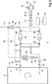
- FIG. 1 gives a schematic and greatly simplified overview of a ventilation system for a control room of a nuclear power plant in the manner of a block flow diagram.
- FIG. 2 shows a modification (extension) of the in FIG. 1 illustrated system.
- the accident ventilation system shown, or ventilation system 2 for short is used to supply fresh air to a control room 4 of a nuclear power plant 6, also known as the control room or in English as the Main Control Room (MCR), in accident or incident situations, especially in the initial phase of a serious incident with the release of nuclear fission products within of the power plant building and, if necessary, in the vicinity.
- MCR Main Control Room
- the ventilation system 2 for the control room 4 is designed on the one hand for a supply of decontaminated and oxygen-rich fresh air - also called supply air - from the surroundings of the control room 4 or the power plant building and is equipped with appropriate filter and cleaning stages.
- the ventilation system 2 effects a removal of used and carbon dioxide-rich air - also called exhaust air - from the control station 4 into the environment.
- there is neither a fresh air supply from an associated compressed air storage system A significant recirculation and reprocessing of the air in the interior of the control station 4 is also provided.
- a supply air line 10 also referred to as a fresh air supply line or fresh air line for short, is connected to the at least approximately hermetically sealed interior 8 of the control center 4, through which fresh air is sucked in from the environment with the help of a fan 12 and into the air supply during operation of the ventilation system 2 Interior 8 is promoted.
- the intake inlet or, for short, inlet 14 of the air supply line 10 can be some distance from the control station 4, in particular outside the power station building.
- the fresh air sucked in via inlet 14 can nevertheless be considerably contaminated with radioactive fission products, in particular in the form of aerosols, iodine and iodine compounds and noble gases.
- These components should be removed as completely and reliably as possible from the fresh air flow - also known as the supply air flow - before it is introduced into the interior space 8 of the control room 4 through a passage 16 in the surrounding wall 18 (only shown partially).
- the HEPA filters 22 accordingly effect a highly efficient separation of the aerosol particles, also referred to as floating particles, from the fresh air flow, in particular with regard to the isotopes Te, Cs, Ba, Ru, Ce, La.
- a second filter stage with an iodine filter 24 and a downstream particle filter 26 is connected into the supply air line 10.
- the iodine filter 24 is preferably implemented in the form of an activated carbon filter bed with a layer thickness of 0.1 to 0.5 m, for example.
- radioactive iodine compounds and elemental iodine are formed in the iodine filter 24 during contact times deposited from 0.1 to 0.5 s.
- Impregnated activated carbon e.g. with potassium iodide as an impregnating agent
- the particle filter 26 connected downstream of the iodine filter 24 is provided to hold back abrasion from the activated carbon bed.
- the fan 12 Connected downstream of the second filter stage is a conveying fan or, for short, a fan 12 for transporting the fresh air flow into the supply air line 10.
- the fan 12 which is preferably electrically driven, has a suction capacity in the range of, for example, 100 to 6,000 m 3 / h.
- a self-sufficient power supply module 28 which is independent of the normal internal power supply and preferably also of the usual (plant-wide) emergency power network, is provided, for example on the basis of electric batteries / accumulators and / or a diesel unit.
- the power supply module 28 is preferably activated independently in the manner of an uninterruptible power supply or, alternatively, is controlled via an assigned control unit 30.
- an air dryer 32 also referred to as a cold trap, is optionally connected into the supply air line 10, with which condensable components can be separated from the fresh air flow.
- it can be a passive cold trap with silica gel and / or ice as the drying agent. This reduces the moisture content of the fresh air stream flowing into the downstream functional units (see below).
- the same purpose is served by an alternatively or additionally present, here in the exemplary embodiment, arranged behind the air dryer 32 in the flow direction of the fresh air, arranged throttle 34 which acts on the fresh air flow according to the principle of expansion drying. It can in particular be a controllable throttle valve.
- the fresh air stream flows through the line section 36, for example, into which a noble gas adsorber column or adsorber column 38 is connected if the associated actuating elements are in the appropriate position (see below).
- the noble gases contained in the fresh air flow especially xenon and krypton, are bound by physical and / or chemical adsorption to the adsorbent present in the adsorber column 38 within the scope of a dynamically established equilibrium and thus delayed in the line section 36 as long as the adsorption capacity of the adsorber column 38 is not yet exhausted.
- one or more layers of activated carbon and / or zeolite and / or molecular sieves can be provided as the adsorbent.
- the adsorber column 38 is followed by a line section leading to the control station 4, into which a particle filter 40 is connected to retain detached adsorber particles.
- the fresh air stream decontaminated in the manner described enters the interior 8 via the duct 16 through the surrounding wall 18 of the control station 4, so that unused, oxygen-rich breathing air is supplied to it with an activity level permissible for the operating personnel.
- the exchange of air is completed by the removal of used, carbon dioxide-rich breathing air from the control room 4 via the exhaust air line 44 connected to its interior 8 and led through the duct 42 in the surrounding wall 18 into the environment, into which a fan 46 is connected to support the gas transport .
- This is preferably an electrically driven blower 46, which, like the blower 12, is supplied with electrical power via the power supply module 28.
- the ventilation system 2 is designed for backwashing the adsorbed noble gases into the environment during operation.
- adsorber columns 38 and 48 which are supplied with fresh air or exhaust air via corresponding line branches and connections as well as actuators, here in the form of 3-way valves, in such a way that one of the two adsorber columns 38 and 48 like already described, acts on the fresh air flow in adsorption operation, while the other is backwashed by the exhaust air flow at the same time in desorption operation or flushing operation and thus made ready for the next adsorption cycle.
- the role of the adsorber columns 38 and 48 can be interchanged and thus cyclically changed between adsorption operation and desorption operation with respect to the respective column.
- this functionality is implemented in that one adsorber column 38 is arranged in the line section 36, and the other adsorber column 48 in flow-wise anti-parallel connection in the line section 50.
- Both line sections 36 and 50 unite on one side in the 3-way valve 52 and on the other side in the union 54 arranged on the suction side of the blower 46.
- switchable cross-connection 60 connected between the two line sections 36 and 50, which is connected via a T connection 62 to the section of the air supply line 10 leading to the particle filter 40.
- a cross-connection 68 that can be switched by the two 3-way valves 64 and 66 is connected, which via a T connection 70 with the section coming from the throttle 34 the supply air line 10 is connected.
- the supply air coming from the throttle 34 flows through the T connection 70, the 3-way valve 66, the adsorber column 38, the 3-way valve 58 and the T, which is lower in the figure -Connection 62 to the particle filter 40 and from there to the control station 4.
- the exhaust air coming from the control station 4 flows through the 3-way valve 52, the 3-way valve 56, the adsorber column at the top in the figure 48 and the 3-way valve 64 to the suction connection of the blower 46 and from there on to an exhaust air chimney or to another outlet 72, which is expediently at some distance from the inlet 14 for fresh air.
- the noble gases accumulated by adsorption in the adsorber column 48 in the previous cycle are desorbed from the adsorbent by the largely noble gas-free exhaust air from the interior 8 of the control station 4 in this operating mode and flushed back into the environment with the exhaust air flow.
- the backwashing is supported by the fan 46 arranged downstream of the backwashed adsorber column 48, the increase in volume of the exhaust air flow due to the negative pressure intensifying the backwashing process of the noble gases.
- a throttle 74 preferably in the form of an adjustable throttle valve, which is used for passive overheating of the exhaust air and is seen in the direction of the exhaust air flow this leads to a reduction in the moisture in the exhaust air (expansion drying). This promotes the desorption speed of the noble gases in the downstream adsorber column 48.
- the fresh air now flows from the throttle 34 via the 3-way valve 64, the adsorber column 48 and the 3-way valve 56 to the particle filter 40 and from there to the control room 4.
- the exhaust air from the control room 4 flows from the throttle 74 via the 3-way valve 52, the 3-way valve 58, the adsorber column 38 and the 3-way valve 66 to the fan 46 and from there to the Outlet 72.
- the previously loaded adsorber column 38 is now backwashed by the exhaust air, while the adsorber column 48 is available for cleaning the fresh air and accordingly for reloading.
- a control unit 30 which expediently also controls the two fans 12 and 46 and, if necessary, further adjusting elements for flow and controls pressures.
- the switchover functionality can also be implemented in an equivalent manner by means of other line topologies and actuators.
- the ventilation system 2 is preferably constructed in a modular manner from a noble gas module 76, an iodine and aerosol module 78 and a power supply module 28.
- the boundaries between the modules can of course also be selected differently in detail, and there can be further modules or submodules.
- the individual modules are, for example, housed in standard containers so that they can be transported, so that they can be easily transported to the place of use and there can be easily assembled by connecting the associated standardized line connections.
- CO 2 carbon dioxide
- chemisorption chemical adsorption
- absorption absorption
- the integration of the CO 2 adsorber column 82 in the off FIG. 1 The known system is preferably carried out in such a way that a recirculation line or circulating air line 80 branching off from the exhaust air line 44 and leading to the supply air line 10 is provided, into which the CO 2 adsorber column 82 is connected.
- a switched into the air circulation duct 80 circulation fan 84 thus promotes return the extracted from the control console 4 CO 2 -rich exhaust air over the CO 2 -Adsorberkolonne 82 having reduced CO 2 content for breathing in the control center 4 in the recirculation mode.
- the CO 2 adsorption takes place almost at the pressure that prevails inside the control room 4, i.e. almost at atmospheric pressure or slightly more (avoidance of in-leakage, see below).
- the circulating air fan 84 does not have to perform any appreciable compression work.
- the circulating air line 80 is connected on the inlet side via a line branching (e.g. a T-piece) to the line section of the exhaust air line 44 located between the passage 42 to the control station 4 and the throttle 74.
- the circulating air line 80 is connected via a branching line to the line section of the supply air line 10 located between the duct 16 and the 3-way valve 58, here specifically upstream of the particle filter 40.
- filters 86 can be connected to the circulating air line 80, here for example, downstream of the CO 2 adsober column 82 (the direction of flow in recirculation mode is indicated by a flow arrow next to the column).
- the air circulation line 80 itself is provided with shut-off valves 88, 90 on the inlet side and on the outlet side in order to be able to isolate it from the rest of the line system if necessary.
- the shut-off valves 88, 90 can preferably be regulated with regard to the flow (regulating valves), so that partial flows can also be set. This also applies to the other valves, in particular the shut-off valves 92, 94 described below.
- the circulating air line 80 is connected via suitable line branches or connections to a line section of the exhaust air line 44 containing the fan 46.
- This line section can be isolated by means of shut-off valves 92, 94 from the outlet 72 and from the part of the ventilation system 2 containing the noble gas adsorber columns 38, 48 and forms a section of the circulating air line 80 in recirculation mode.
- the CO 2 adsorber column 82 is preferably downstream of the fan, as shown 46 (or more generally: the circulating air fan 84), on its pressure side, arranged.
- the shut-off valve 94 is preferably a controllable 3-way valve at the branching line which, during desorption operation (backwashing) of the noble gas adsorber column 38 or 48, releases the outlet 72 and shuts off the connected branch of the circulating air line 80. This ensures that the activities released by the noble gas adsorber column 38 or 48 during desorption are blown out into the environment and are not transported to the control station 4 via the circulating air line 80.
- the noble gas desorption mode (flushing of the noble gas adsorber column 38 or 48) and the CO 2 adsorption mode (circulating air mode) are therefore preferably not run at the same time.
- the noble gas adsorption mode (loading of the noble gas adsorber column 38 or 48) and the CO2 adsorption mode (recirculation mode) can, however, be run simultaneously without any problems.
- filtered fresh air is blown into the control station 4 via at least one of the two noble gas adsorber columns 38 or 48 and the supply air line 10.
- the shut-off valve 88 When the shut-off valve 88 is open, the exhaust air from the control station 4 is transported through the circulating air line 80 by means of the fan 46.
- a more or less large partial flow (which may also have the value zero) is released into the ambient atmosphere via the outlet 72 and the remaining partial flow via the CO2 adsorber column 82 returned to control room 4.
- the shut-off valve 92 is closed, so that as above mentions the undesired return of activities from the noble gas adsorber columns 38 or 48 to the control station 4 is avoided.
- Another possible mode of operation includes the simultaneous adsorption and desorption operation of the noble gas adsorber columns 38 or 48 in recurring alternation, as already in connection with FIG FIG. 1 described.
- this operating mode as mentioned above, there is preferably no CO2 adsorption in recirculation mode.
- the physical adsorption in the noble gas adsorber columns 38 or 48 at higher pressure is significantly more effective than at atmospheric pressure, while the desorption preferably takes place at relatively low pressure, in particular at a slight negative pressure in relation to atmospheric pressure .
- a certain period of time of 10 to 30 minutes, for example, must be planned for the required pressure increase by means of the fan 12, which acts as a compressor, after each changeover process.
- the control station 4 is preferably only ventilated by CO2 adsorption in circulating air mode.
- the oxygen content of the air in the control room 4 which is occupied by operating personnel, slowly decreases due to consumption, the CO2 content is safely kept below a critical value. Later, after reaching the operating pressure required for effective retention of the noble gas, the filtered air supply is preferably added via the noble gas adsorber columns 38 or 48 (simultaneous operation of noble gas adsorption and CO2 adsorption as described above). As a result, the previously reduced oxygen content in the air in the control room 4 is refreshed again. Regeneration phases (desorption) can be carried out later with the circulating air switched off and the adsorber columns 38 and 40 exchanged.
- the control station 4 - preferably exclusively - in the required period of time to increase the pressure in the adsorber columns 38, 48 Air circulation is supplied. After the pressure increase, fresh air is preferably fed in during / together with the chemical CO2 adsorption via the inert gas delay section with the adsorber columns 38, 48.
- the increased volume flow is advantageously used to maintain the oxygen concentration and to increase the pressure in the control room 4.
- a directed flow with overpressure in the control station 4 is generated in relation to the external environment, which reliably prevents the penetration of activity from the outside into the control station 4 (in-leakage). Simple systems that only work with CO 2 separation cannot guarantee this task with sufficient reliability.
- the adsorbent used for CO2 adsorption in the adsorber column 82 can be, for example, soda lime, zeolite / molecular sieve or a regenerable adsorbent. Oxides, peroxides and hyperoxides (e.g. potassium hyperoxide) can be used as further examples of possible adsorbents. Regenerable adsorbents can consist of metal oxides or mixtures thereof. This is how z. B. silver oxide with CO 2 to silver carbonate. In principle, mixtures of the adsorbents mentioned can also be used or multistage adsorber columns with adsorbents of the same type or different adsorbents can be implemented in the various stages.
- the chemical sorption taking place in the adsorber column 82 can be reversibly carried out at elevated temperatures and the adsorbent can in principle be regenerated.
- simple modifications in the routing of the air circulation system may be useful in order to be able to carry out such regeneration phases outside of the above-described air circulation operation without loading the control station 4.
- the systems guarantee FIG. 1 and FIG. 2 that in addition to the airborne activity of the aerosols and organoiodine, the noble gases are also held back by the air in the control room.
- the CO 2 is removed from the air by chemical adsorption / absorption.
- the control station 4 can be operated in recirculation mode in extreme accident situations until the oxygen concentration in the control room falls to a lower limit (approx. 17-19% by volume), so that a fresh air supply from outside is required .
- the noble gas retention module with the adsorber columns 38, 48 is then operated primarily to cover and increase the oxygen content.
- the required capacity of the module in terms of drive energy and amount of activated carbon can be reduced considerably.
- the compression energy required to generate pressure swing adsorption can be minimized. As a result, the units required for the self-sufficient generation of energy can be made smaller.
- the ventilation system 2 can also be used for the accident ventilation of other room areas within a nuclear power plant or, more generally, of a nuclear facility - such as fuel storage facilities, reprocessing plants , fuel-processing systems etc. - can be used, for example, by auxiliary system buildings, switchgear rooms, control rooms or other control and monitoring rooms.
- a nuclear facility - such as fuel storage facilities, reprocessing plants , fuel-processing systems etc. - can be used, for example, by auxiliary system buildings, switchgear rooms, control rooms or other control and monitoring rooms.
- the term "operating room” is also used in a summarizing, keyword-like manner.
Description
In einem Kernkraftwerk muss bei Stör- oder Unfallsituationen abhängig vom jeweiligen Störfall und von gegebenenfalls eingeleiteten Gegenmaßnahmen mit einer möglicherweise signifikanten Freisetzung von radioaktiven Spaltprodukten, insbesondere Jod, Aerosole und Edelgasen gerechnet werden. Durch Leckagen des Containments muss hierbei, bevor es zu einer Freisetzung in die Kraftwerksumgebung kommt, auch mit einer Freisetzung und Verteilung von Aktivität in den Kraftwerksgebäuden (z. B. Hilfsanlagengebäude, Schaltanlage, Warte, etc.) ausgegangen werden. Hierbei stellt insbesondere, neben der Freisetzung von aerosolgebundener Aktivität, die Freisetzung von Edelgasen ein Problem für das Kraftwerkspersonal dar.In a nuclear power plant, a potentially significant release of radioactive fission products, in particular iodine, aerosols and noble gases, must be expected in the event of incidents or accidents, depending on the incident in question and any countermeasures introduced. Due to leakages in the containment, before a release into the power plant environment occurs, a release and distribution of activity in the power plant buildings (e.g. auxiliary system building, switchgear, control room, etc.) must be assumed. In addition to the release of aerosol-bound activity, the release of noble gases is a particular problem for power plant personnel.
Zu einer massiven Edelgasfreisetzung kommt es unter Umständen auch bei der Einleitung einer gefilterten Druckentlastung und der Ausbildung einer Edelgaswolke über dem Kraftwerksgelände. Je nach Wetterlage kann eine längerfristige Belastung nicht vollkommen ausgeschlossen werden.A massive noble gas release may also occur when a filtered pressure relief is initiated and a noble gas cloud forms over the power plant site. Depending on the weather, long-term exposure cannot be completely ruled out.
Für die Einleitung von sogenannten Accident-Management Maßnahmen ist es zwingend erforderlich, dass die Bedingungen in der auch als Leitstand oder Leitwarte bezeichneten Warte einen Aufenthalt des Betriebspersonals ermöglichen, ohne dass es zu einer unzulässigen Strahlenbelastung und Kontamination des Personals kommt.In order to initiate so-called accident management measures, it is imperative that the conditions in the control room, also known as the control room or control room, allow operating personnel to stay without inadmissible radiation exposure and contamination of the personnel.
Bei auslegungsüberschreitenden Störfällen mit "Station Black-Out" (SBO) stehen die bestimmungsgemäßen bzw. normalbetrieblichen Lüftungs- und Filteranlagen nicht mehr zur Verfügung, um die wesentlichen lüftungstechnischen Parameter zur Aufrechterhaltung der Begehbarkeit der Warte zu gewährleisten.In the event of incidents beyond the scope of design and "station black-out" (SBO), the intended or normal operating ventilation and filter systems are no longer available in order to guarantee the essential ventilation parameters for maintaining the accessibility of the control room.
Bisherige Konzepte sehen zur Beherrschung derartiger Szenarien eine Isolation der Warte vor. Die Versorgung erfolgt beispielsweise mit mobilen Belüftungsanlagen, die mit verschiedenen Filtern ausgestattet sind. Eine zufriedenstellende Edelgasrückhaltung ist mit diesen Anlagen nicht möglich.Previous concepts provide for an isolation of the control room to control such scenarios. The supply takes place, for example, with mobile ventilation systems that are equipped with various filters. A satisfactory retention of inert gas is not possible with these systems.
Andere Konzepte versorgen die Warte mit gespeicherter Druckluft. Die Lagerhaltung in Druckbehältern für einen größeren Zeitraum ist jedoch sehr aufwändig und daher begrenzt. Ein modularer und mobiler Systemaufbau ist praktisch nicht möglich. Druckspeicherkonzepte erfordern überdies einen hohen Aufwand bei einer Nachrüstung in laufenden Anlagen.Other concepts supply the control room with stored compressed air. However, storage in pressure vessels for a longer period of time is very complex and therefore limited. A modular and mobile system structure is practically not possible. Pressure accumulator concepts also require a lot of effort when retrofitting in running systems.
Der Erfindung liegt die Aufgabe zugrunde, ein möglichst einfach und kompakt gehaltenes Belüftungssystem für einen Leitstand einer kerntechnischen Anlage oder einen ähnlichen von Betriebspersonal begehbaren Raum anzugeben, welches bei schweren Störfällen mit Freisetzung von radioaktiver Aktivität zumindest für eine Zeitspanne von einigen Stunden eine Zufuhr von dekontaminierter Frischluft ermöglicht, so dass es zu einer möglichst geringen Strahlenbelastung von im Leitstand anwesendem Betriebspersonal kommt. Insbesondere soll dabei der Anteil von radioaktiven Edelgasen in der dem Leitstand zugeführten Frischluft möglichst gering sein. Das Belüftungssystem soll ferner einen möglichst passiven Charakter besitzen und nur wenig elektrische Energie verbrauchen. Des Weiteren soll ein besonders vorteilhaftes Verfahren zum Betreiben eines derartigen Belüftungssystems angegeben werden.The invention is based on the object of specifying a ventilation system, kept as simple and compact as possible, for a control room of a nuclear facility or a similar room accessible by operating personnel, which in the event of severe incidents with the release of radioactive activity, a supply of decontaminated fresh air for at least a few hours so that there is as little radiation exposure as possible to the operating staff present in the control room. In particular, the proportion of radioactive noble gases in the fresh air supplied to the control room should be as low as possible. The ventilation system should also be as passive as possible and consume little electrical energy. Furthermore, a particularly advantageous method for operating such a ventilation system is to be specified.
In Bezug auf die Vorrichtung wird die Aufgabe erfindungsgemäß gelöst durch die Merkmale des Anspruchs 1. In Bezug auf das Verfahren wird die Aufgabe gelöst durch die Merkmale des Anspruchs 11.With regard to the device, the object is achieved according to the invention by the features of claim 1. With regard to the method, the object is achieved by the features of claim 11.
Vorteilhafte Ausgestaltungen sind Gegenstand der Unteransprüche und gehen im Übrigen aus der nachfolgenden detaillierten Beschreibung hervor.Advantageous refinements are the subject matter of the subclaims and otherwise emerge from the following detailed description.
Das erfindungsgemäße Belüftungssystem weist unter anderem vorteilhafterweise ein Aerosol- und Jodfiltermodul auf. Die Ansaugluft in der Zuluftleitung wird hierbei über ein Gebläse angesaugt und über Schwebstofffilter zur Abscheidung der Aerosole geführt. Nach der Abscheidung der Schwebstoffe werden vorteilhafterweise radioaktive Jodverbindungen in einem Aktivkohlefilterbett abgeschieden. Zur Abscheidung des radioaktiven Methyljodids durch Isotopentausch oder Salzbildung kann imprägnierte Aktivkohle eingesetzt werden. Dem Aktivkohlebett ist vorteilhafterweise zur Rückhaltung von Abrieb ein Partikelfilter nachgeschaltet.The ventilation system according to the invention advantageously has, inter alia, an aerosol and iodine filter module. The intake air in the supply air line is here Sucked in by a fan and fed through a particulate filter to separate the aerosols. After the suspended matter has been separated out, radioactive iodine compounds are advantageously separated out in an activated carbon filter bed. Impregnated activated carbon can be used to separate the radioactive methyl iodide through isotope exchange or salt formation. A particle filter is advantageously connected downstream of the activated carbon bed in order to retain abrasion.
Die so gefilterte Luft wird dann in einem zweiten Prozessschritt einem Edelgasmodul zugeführt. Das Edelgasmodul beinhaltet im Wesentlichen zwei Adsorberkolonnen in Zwillingskonfiguration, die mit Adsorbens/Adsorbensien, vorzugsweise Aktivkohle, gefüllt sind. Das Adsorbens der Kolonnen kann auch aus mehreren Schichten von Aktivkohle und/oder Zeolith und/oder Molekularsieben aufgebaut sein.The air filtered in this way is then fed to a noble gas module in a second process step. The noble gas module essentially contains two adsorber columns in a twin configuration, which are filled with adsorbent / adsorbents, preferably activated carbon. The adsorbent of the columns can also be built up from several layers of activated carbon and / or zeolite and / or molecular sieves.
Die Zuluft tritt in die erste Adsorberkolonne ein, wobei die Edelgase wie z. B. Xenon, Krypton durch eine dynamische Adsorption bei ihrem Durchlauf durch die Kolonne verzögert werden. Nach der Kolonne ist zweckmäßigerweise ein Filter zur Rückhaltung von Adsorberpartikeln angeordnet.The supply air enters the first adsorber column, the noble gases such. B. Xenon, krypton are delayed by dynamic adsorption as they pass through the column. After the column, a filter for retaining adsorber particles is expediently arranged.
Die Abluft aus dem zu versorgenden Raumbereich wird gleichzeitig über die zweite Adsorberkolonne geführt und bewirkt dort eine Rückspülung der zuvor akkumulierten Edelgasaktivität, so dass diese Kolonne wieder zur Beladung nach der Umschaltung bereit steht. Die Umschaltung wird spätestens kurz vor dem Durchbruch der Aktivität in der ersten Adsorberkolonne vorgenommen, wobei diese dann mit der Abluft rückgespült wird. Die Umschaltung wird vorzugsweise passiv durch ein Zeitglied oder eine Aktivitätsmessung ausgelöst.The exhaust air from the area of the room to be supplied is simultaneously led over the second adsorber column and there causes the previously accumulated noble gas activity to be backwashed so that this column is ready for loading again after the switchover. The switchover is carried out at the latest shortly before the breakthrough of activity in the first adsorber column, which is then backwashed with the exhaust air. The switchover is preferably triggered passively by a timer or an activity measurement.
Die Rückspülung wird vorteilhafterweise durch ein Gebläse in der Abluftleitung unterstützt, wobei die Volumenvergrößerung des Abluftstroms durch den Unterdruck den Rückspülprozess der Edelgase verstärkt.The backwashing is advantageously supported by a fan in the exhaust air line, the increase in volume of the exhaust air flow due to the negative pressure intensifying the backwashing process of the noble gases.
In der Abluftleitung der Warte befindet sich vorteilhafterweise eine Drossel, die zur passiven Überhitzung der Abluft und damit zu einer Verringerung der in der Abluft befindlichen Feuchtigkeit führt (Expansionstrocknung). Dadurch wird die Desorptionsgeschwindigkeit der Edelgase in der nachgeschalteten, zu spülenden Adsorberkolonne begünstigt.In the exhaust air line of the control room there is advantageously a throttle which is used to passively overheat the exhaust air and thus to reduce the amount in the exhaust air moisture (expansion drying). This promotes the desorption speed of the noble gases in the downstream adsorber column to be purged.
In der Zuluftleitung zum Edelgasmodul befinden sich vorteilhafterweise eine Drossel und/oder ein Lufttrockner, um zu verhindern, dass zu hohe Feuchtigkeit auf die Edelgaskolonnen gefördert wird.A throttle and / or an air dryer are advantageously located in the supply air line to the noble gas module in order to prevent excessive moisture from being conveyed to the noble gas columns.
Das Edelgasmodul kann zusätzlich mit einem passiven Kühlspeicher zur Erhöhung der k-Werte ausgerüstet werden. Der k-Wert beschreibt in diesem Zusammenhang die Adsorptionskapazität des Adsorbermaterials für Edelgas in z. B. der Einheit cm3 Edelgas / g Adsorbens. Der k-Wert ist abhängig von der Temperatur, dem Druck und Feuchtegehalt des Gases. Er wird in der Regel empirisch ermittelt.The noble gas module can also be equipped with a passive cooling store to increase the k values. In this context, the k value describes the adsorption capacity of the adsorber material for noble gas in e.g. B. the unit cm 3 noble gas / g adsorbent. The k-value depends on the temperature, pressure and moisture content of the gas. It is usually determined empirically.
Die Adsorberkolonnen werden bevorzugt im Druckwechselverfahren betrieben, d. h. Unterdruck der zu spülenden Kolonne und Überdruck der zu beladenden Kolonne (jeweils in Relation zum Atmosphärendruck), um die k-Werte der Kolonnen zu verbessern und deren Abmessungen zu reduzieren. Der Überdruck in der von der Zuluft durchströmten Adsorberkolonne wird beispielsweise mit einem Einstellventil in der Zuluftleitung reguliert.The adsorber columns are preferably operated in the pressure swing process, d. H. Underpressure of the column to be flushed and overpressure of the column to be loaded (each in relation to atmospheric pressure) in order to improve the k values of the columns and reduce their dimensions. The overpressure in the adsorber column through which the supply air flows is regulated, for example, with an adjusting valve in the supply air line.
Die Abluft wird zusammen mit den rückgespülten Edelgasen in die Kraftwerksumgebung mit genügend Abstand zu der Zuluftansaugung abgegeben.The exhaust air is released together with the back-flushed noble gases into the power plant environment at a sufficient distance from the supply air intake.
Das Belüftungssystem umfasst zweckmäßigerweise eine Steuerung und entsprechende Einstellorgane für Durchfluss und Drücke.The ventilation system expediently comprises a control system and corresponding adjusting elements for flow and pressures.
Die mit der Erfindung erzielten Vorteile bestehen insbesondere darin, dass neben den luftgetragenen Aktivitäten in Form von Aerosolen und Jod / Jodverbindungen (insbesondere Organojod) zugleich die radioaktiven Edelgase von der Zuluft der Warte zurückgehalten werden. Mit dem Druckwechsel- und Spülverfahren der Zwillingskolonnen können selbst langlebige Edelgasisotope wie Krypton-85 zuverlässig aus dem Zuluftstrom abgeschieden werden. Die zur Entfernung der Edelgase von dem Sorbens / Adsorbens benötigten Bedingungen werden passiv durch Expansionsüberhitzung unterstützt. Bedarf an elektrischem Betriebsstrom besteht im Wesentlichen nur für die Gebläse in der Zuluft- und der Abluftleitung sowie in geringem Umfang für die zugeordnete Steuereinheit und für die Umschaltmittel zur Umschaltung zwischen den Betriebszyklen. Dieser Bedarf kann problemlos mit einem autarken Energieversorgungsmodul (z. B. durch Batterien und/oder ein Dieselaggregat) für mindestens 72 h gedeckt werden.The advantages achieved with the invention are in particular that, in addition to the airborne activities in the form of aerosols and iodine / iodine compounds (especially organoiodine), the radioactive noble gases are also retained from the air supply to the control room. With the pressure change and flushing process of the twin columns, even long-lived noble gas isotopes such as krypton-85 can be reliably separated from the supply air flow. The one to remove the noble gases Conditions required by the sorbent / adsorbent are passively supported by expansion superheating. There is essentially only a need for electrical operating current for the fans in the supply air and exhaust air lines and, to a lesser extent, for the assigned control unit and for the switching means for switching between the operating cycles. This requirement can easily be met with a self-sufficient energy supply module (e.g. with batteries and / or a diesel generator) for at least 72 hours.
Zusammengefasst werden zur Sicherstellung der Begehbarkeit der Warte folgende Funktionen gewährleistet:
- Isolation der Wartenlüftung von den restlichen Gebäudeteilen
- Überdruck gegenüber den angrenzenden Gebäuderäumen (z. B. < 1 mbar)
- Einhaltung der zulässigen Kohlenmonoxid- und Kohlendioxid-Konzentration
- Jodrückhaltung
- Aersolrückhaltung
- Rückhaltung der Edelgase (z. B. Kr, Xe)
- Begrenzung der Dosis (z. B. < 100 mSv/7d)
- Temperaturbegrenzung zur Einhaltung der l&C Temperatur-Qualifikationen
- Sicherstellung der oben genannten Funktionen für mindestens 72 h
- Isolation of the control room ventilation from the rest of the building
- Overpressure compared to the adjacent building rooms (e.g. <1 mbar)
- Compliance with the permissible carbon monoxide and carbon dioxide concentration
- Iodine retention
- Aerosol retention
- Retention of noble gases (e.g. Kr, Xe)
- Limit the dose (e.g. <100 mSv / 7d)
- Temperature limit to comply with l & C temperature qualifications
- Ensuring the above-mentioned functions for at least 72 hours
Weitere Vorteile sind in stichpunktartiger Zusammenfassung:
- modularer und mobiler Systemaufbau
- geringer Aufwand und hohe Flexibilität bei Integration in laufende Anlagen
- geringer Wartungsaufwand
- eine aufwendige Lagerhaltung von atemfähiger Luft entfällt
- Abdeckung größerer Luftmengen (Luftwechsel) und Raumbereiche möglich
- modular and mobile system structure
- low effort and high flexibility when integrated into running systems
- low maintenance
- Costly storage of breathable air is no longer necessary
- Covering larger amounts of air (air exchange) and room areas possible
Ein Ausführungsbeispiel der Erfindung wird nachfolgend anhand von Zeichnungen näher erläutert.An exemplary embodiment of the invention is explained in more detail below with reference to drawings.
Das in
In derartigen Szenarien, die üblicherweise mit dem Ausfall der Eigenstromversorgung des Kernkraftwerkes 6 und damit auch mit dem Ausfall des normalbetrieblichen Belüftungssystems (nicht dargestellt) für den Leitstand 4 einhergehen, kommt es in besonderem Maße darauf an, den Leitstand 4 noch für eine gewisse Zeitspanne - etwa bis zu 72 h nach dem Einsetzen des Störfalls - ohne Gefährdung des Bedienpersonals besetzt halten zu können, um anfängliche Gegenmaßnahmen einzuleiten und zu überwachen. Möglicherweise muss das Bedienpersonal auch so lange in dem Leitstand 4 verharren, bis nach dem Abklingen eines anfänglichen Aktivitätsmaximums in der Umgebung eine sichere Evakuierung möglich ist.In such scenarios, which are usually associated with the failure of the internal power supply of the
Zu diesem Zweck ist das Belüftungssystem 2 für den Leitstand 4 einerseits für eine Zufuhr von dekontaminierter und sauerstoffreicher Frischluft - auch Zuluft genannt - aus der Umgebung des Leitstandes 4 oder des Kraftwerksgebäudes ausgelegt und mit entsprechenden Filter- und Reinigungsstufen ausgestattet. Andererseits bewirkt das Belüftungssystem 2 einen Abtransport von verbrauchter und kohlendioxidreicher Luft - auch Abluft genannt - aus dem Leitstand 4 in die Umgebung. Im Gegensatz zu anderen, bislang gebräuchlichen Konzepten ist dabei weder eine Frischluftzufuhr aus einem zugehörigen Druckluftspeichersystem noch eine nennenswerte Rezirkulation und Wiederaufbereitung der Luft im Innenraum des Leitstandes 4 vorgesehen.For this purpose, the
Konkret ist an den zumindest näherungsweise hermetisch gegenüber der äußeren Umgebung gekapselten Innenraum 8 des Leitstandes 4 eine auch als Frischluftzufuhrleitung oder kurz Frischluftleitung bezeichnete Zuluftleitung 10 angeschlossen, über die während des Betriebes des Belüftungssystems 2 mit Hilfe eines Gebläses 12 Frischluft aus der Umgebung angesaugt und in den Innenraum 8 gefördert wird. Der Ansaugeinlass oder kurz Einlass 14 der Zuluftleitung 10 kann in einiger Entfernung zum Leitstand 4 liegen, insbesondere außerhalb des Kraftwerksgebäudes. Je nach Störfallverlauf kann die über den Einlass 14 angesaugte Frischluft dennoch erheblich mit radioaktiven Spaltprodukten, insbesondere in Gestalt von Aerosolen, Jod und Jodverbindungen sowie Edelgassen belastet sein. Diese Bestandteile sollten möglichst vollständig und zuverlässig aus dem Frischluftstrom - auch Zuluftstrom genannt - entfernt werden, bevor dieser durch eine Durchführung 16 in der Umfassungswand 18 (nur ausschnittsweise dargestellt) hindurch in den Innenraum 8 des Leitstandes 4 eingeleitet wird.Specifically, a
Hierzu ist in Richtung des Frischluftstroms gesehen stromabwärts des Einlasses 14 eine erste Filterstufe in Gestalt eines Aerosolfilters 20 in die Zuluftleitung 10 geschaltet, hier im Beispiel realisiert durch zwei strömungsmäßig parallel geschaltete HEPA-Filter 22 (HEPA = High Efficiency Particulate Airfilter, zu Deutsch sinngemäß Schwebstofffilter). Die HEPA-Filter 22 bewirken demnach eine hocheffiziente Abscheidung der auch als Schwebeteilchen bezeichneten Aerosolpartikel aus dem Frischluftstrom, insbesondere in Bezug auf die Isotope Te, Cs, Ba, Ru, Ce, La.For this purpose, a first filter stage in the form of an
Weiter stromabwärts ist eine zweite Filterstufe mit einem Jodfilter 24 und einem nachgeschalteten Partikelfilter 26 in die Zuluftleitung 10 geschaltet. Der Jodfilter 24 ist bevorzugt in Gestalt eines Aktivkohlefilterbetts mit einer Schichtdicke von beispielsweise 0,1 bis 0,5 m verwirklicht. Nach der zuvor im Aerosolfilter 20 erfolgten Abscheidung der Schwebstoffe werden in dem Jodfilter 24 radioaktive Jodverbindungen und elementares Jod beispielsweise mit einem k-Wert > 8 bei Kontaktzeiten von 0,1 bis 0,5 s abgeschieden. Zur Abscheidung des radioaktiven Methyljodids durch Isotopentausch oder Salzbildung kann imprägnierte Aktivkohle (z. B. mit Kaliumjodid als Imprägnierungsmittel) eingesetzt werden. Der dem Jodfilter 24 nachgeschaltete Partikelfilter 26 ist zur Rückhaltung von Abrieb aus dem Aktivkohlebett vorgesehen.Further downstream, a second filter stage with an
Stromabwärts der zweiten Filterstufe ist ein Fördergebläse oder kurz Gebläse 12 zum Transport des Frischluftstroms in die Zuluftleitung 10 geschaltet. Das vorzugsweise elektrisch angetriebene Gebläse 12 besitzt eine Ansaugleistung im Bereich von beispielsweise 100 bis 6.000 m3/h.Connected downstream of the second filter stage is a conveying fan or, for short, a
Zur Bereitstellung des erforderlichen Betriebsstroms ist ein autarkes, von der normalbetrieblichen Eigenstromversorgung und vorzugsweise auch vom gewöhnlichen (anlagenweiten) Notstromnetz unabhängiges Stromversorgungsmodul 28 vorgesehen, etwa auf der Basis von elektrischen Batterien / Akkumulatoren und/oder eines Dieselaggregats. Das Stromversorgungsmodul 28 aktiviert sich im Anforderungsfall vorzugsweise eigenständig nach Art einer unterbrechungsfreien Stromversorgung oder wird alternativ über eine zugeordnete Steuereinheit 30 angesteuert.To provide the required operating current, a self-sufficient
Weiter stromabwärts ist optional ein auch als Kühlfalle bezeichneter Lufttrockner 32 in die Zuluftleitung 10 geschaltet, mit dem sich kondensierbare Bestandteile aus den Frischluftstrom abtrennen lassen. Es kann sich beispielsweise um eine passive Kühlfalle mit Silikagel und/oder Eis als Trocknungsmittel handeln. Dadurch wird der Feuchtigkeitsgehalt des in die nachgeschalteten Funktionseinheiten (siehe unten) strömenden Frischluftstroms reduziert. Demselben Zweck dient eine alternativ oder zusätzlich vorhandene, hier im Ausführungsbeispiel in Strömungsrichtung der Frischluft gesehen hinter dem Lufttrockner 32 angeordnete Drossel 34, welche nach dem Prinzip der Expansionstrocknung auf den Frischluftstrom einwirkt. Es kann sich dabei insbesondere um ein regelbares Drosselventil handeln.Further downstream, an
Im Anschluss an die Filterung und Trocknung durchströmt der Frischluftstrom bei entsprechender Stellung zugehöriger Stellorgane (siehe unten) beispielsweise den Leitungsabschnitt 36, in den eine Edelgas-Adsorberkolonne oder kurz Adsorberkolonne 38 geschaltet ist. Dabei werden die im Frischluftstrom enthaltenen Edelgase, vor allem Xenon und Krypton, im Rahmen eines sich dynamisch einstellenden Gleichgewichts durch physikalische und/oder chemische Adsorption an das in der Adsorberkolonne 38 vorhandene Adsorbens gebunden und somit in dem Leitungsabschnitt 36 verzögert, solange die Adsorptionskapazität der Adsorberkolonne 38 noch nicht erschöpft ist. Als Adsorbens können insbesondere ein oder mehrere Schichten Aktivkohle und/oder Zeolith und/oder Molekularsiebe vorgesehen sein.Following the filtering and drying, the fresh air stream flows through the
Der Adsorberkolonne 38 ist ein zum Leitstand 4 führender Leitungsabschnitt nachgeschaltet, in den ein Partikelfilter 40 zur Rückhaltung von abgelösten Adsorberpartikeln geschaltet ist.The
Schließlich tritt der auf die beschriebene Weise dekontaminierte Frischluftstrom über die Durchführung 16 durch die Umfassungswand 18 des Leitstandes 4 in dessen Innenraum 8 ein, so dass diesem unverbrauchte, sauerstoffreiche Atemluft mit einem für das Betriebspersonal zulässigen Aktivitätsgrad zugeführt wird.Finally, the fresh air stream decontaminated in the manner described enters the interior 8 via the
Vervollständigt wird der Luftaustausch durch die Abfuhr von verbrauchter, kohlendioxidreicher Atemluft aus dem Leitstand 4 über die mit dessen Innenraum 8 verbundene und durch die Durchführung 42 in der Umfassungswand 18 in die Umgebung geführte Abluftleitung 44, in die zur Unterstützung des Gastransports ein Gebläse 46 geschaltet ist. Dabei handelt es sich vorzugsweise um ein elektrisch angetriebenes Gebläse 46, das ebenso wie das Gebläse 12 über das Stromversorgungsmodul 28 mit elektrischem Strom versorgt wird.The exchange of air is completed by the removal of used, carbon dioxide-rich breathing air from the
Da das Adsorptionsvermögen der auf den Frischluftstrom einwirkenden Adsorberkolonne 38 bei praktikabler Baugröße üblicherweise schon nach relativ kurzer Betriebsdauer erschöpft ist, ist das Belüftungssystem 2 für eine Rückspülung der adsorbierten Edelgase in die Umgebung im laufenden Betrieb ausgelegt. Zu diesem Zweck sind zwei im Wesentlichen baugleiche Adsorberkolonnen 38 und 48 vorhanden, die über entsprechende Leitungsverzeigungen und -anschlüsse sowie Stellorgane, hier in Form von 3-Wege-Ventilen, derart mit Frischluft oder mit Abluft beaufschlagt werden, dass eine der beiden Adsorberkolonnen 38 und 48 wie bereits beschrieben im Adsorptionsbetrieb auf den Frischluftstrom einwirkt, während die andere zeitgleich im Desorptionsbetrieb bzw. Spülbetrieb durch den Abluftstrom rückgespült und somit für den nächsten Adsorptionszyklus bereit gemacht wird. Durch Umschalten der Stellorgane kann die Rolle der Adsorberkolonnen 38 und 48 vertauscht und somit in Bezug auf die jeweilige Kolonne zyklisch zwischen Adsorptionsbetrieb und Desorptionsbetrieb gewechselt werden.Since the adsorptive capacity of the
Bei dem in der Figur dargestellten Ausführungsbeispiel ist diese Funktionalität dadurch realisiert, dass die eine Adsorberkolonne 38 in dem Leitungsabschnitt 36 angeordnet ist, und die andere Adsorberkolonne 48 in strömungsmäßiger Antiparallelschaltung in dem Leitungsabschnitt 50. Beide Leitungsabschnitte 36 und 50 vereinen sich auf der einen Seite in dem 3-Wege-Ventil 52 und auf der anderen Seite in der auf der Saugseite des Gebläses 46 angeordneten Vereinigung 54. Ferner ist auf der einen Seite zwischen dem 3-Wege-Ventil 52 und den beiden Adsorberkolonnen 38, 48 eine durch die beiden 3-Wege-Ventile 56 und 58 schaltbare Querverbindung 60 zwischen die beiden Leitungsabschnitte 36 und 50 geschaltet, die über einen T-Anschluss 62 mit dem zum Partikelfilter 40 führenden Abschnitt der Zuluftleitung 10 verbunden ist. Auf der anderen Seite ist in analoger Ausgestaltung zwischen den Adsorberkolonnen 38, 48 und der Vereinigung 54 eine durch die beiden 3-Wege-Ventile 64 und 66 schaltbare Querverbindung 68 geschaltet, die über einen T-Anschluss 70 mit dem von der Drossel 34 kommenden Abschnitt der Zuluftleitung 10 verbunden ist.In the embodiment shown in the figure, this functionality is implemented in that one
Bei entsprechend gewählten Ventilstellungen strömt wie bereits weiter oben beschrieben die von der Drossel 34 kommende Zuluft über den T-Anschluss 70, das 3-Wege-Ventil 66, die in der Figur untere Adsorberkolonne 38, das 3-Wege-Ventil 58 und den T-Anschluss 62 zum Partikelfilter 40 und von dort weiter zum Leitstand 4. In dem anderen Leitungsstrang strömt die vom Leitstand 4 kommende Abluft über das 3-Wege-Ventil 52, das 3-Wege-Ventil 56, die in der Figur obere Adsorberkolonne 48 und das 3-Wege-Ventil 64 zum Sauganschluss des Gebläses 46 und von dort weiter zum einem Abluftkamin oder zu einem sonstigen Auslass 72, der zweckmäßigerweise in einiger Entfernung zum Einlass 14 für Frischluft liegt.With appropriately selected valve positions, as already described above, the supply air coming from the
Das heißt, die im vorherigen Zyklus in der Adsorberkolonne 48 durch Adsorption akkumulierten Edelgase werden in diesem Betriebsmodus durch die weitgehend edelgasfreie Abluft aus dem Innenraum 8 des Leitstandes 4 von dem Adsorbens desorbiert und mit dem Abluftstrom in die Umgebung zurückgespült. Die Rückspülung wird durch das stromabwärts der rückgespülten Adsorberkolonne 48 angeordnete Gebläse 46 unterstützt, wobei die Volumenvergrößerung des Abluftstroms durch den Unterdruck den Rückspülprozess der Edelgase verstärkt.That is, the noble gases accumulated by adsorption in the
In der Abluftleitung 44 von der Warte befindet sich in Richtung des Abluftstroms gesehen stromaufwärts des 3-Wege-Ventils 52 und somit stromaufwärts der gerade im Spülbetrieb befindlichen Adsorberkolonne 48 eine Drossel 74, vorzugsweise in Gestalt eines einstellbaren Drosselventils, die zur passiven Überhitzung der Abluft und damit zu einer Verringerung der in der Abluft befindlichen Feuchtigkeit führt (Expansionstrocknung). Dadurch wird die Desorptionsgeschwindigkeit der Edelgase in der nachgeschalteten Adsorberkolonne 48 begünstigt.In the
Nach der Umschaltung vertauschen sich die Rollen der Adsorberkolonnen 38 und 48. Nun strömt die Frischluft von der Drossel 34 kommend über das 3-Wege-Ventil 64, die Adsorberkolonne 48 und das 3-Wege-Ventil 56 zum Partikelfilter 40 und von dort zum Leitstand 4. Die Abluft aus dem Leitstand 4 hingegen strömt von der Drossel 74 kommend über das 3-Wege-Ventil 52, das 3-Wege-Ventil 58, die Adsorberkolonne 38 und das 3-Wege-Ventil 66 zum Gebläse 46 und von dort zum Auslass 72. Die zuvor beladene Adsorberkolonne 38 wird nun durch die Abluft rückgespült, während die Adsorberkolonne 48 für eine Reinigung der Frischluft und dementsprechend für eine erneute Beladung zur Verfügung steht.After the switchover, the roles of the
Zur Steuerung der Umschaltvorgänge mittels der 3-Wege-Ventile 52, 56, 58, 64, 66 ist eine Steuereinheit 30 vorgesehen, welche zweckmäßigerweise auch die beiden Gebläse 12 und 46 und gegebenenfalls weitere Stellorgane für Durchfluss und Drücke ansteuert. Für den Fachmann versteht sich, dass die Umschaltfunktionalität auch mittels anderer Leitungstopologien und Stellorgane in äquivalenter Weise realisiert werden kann.To control the switching processes by means of the 3-
Wie durch die gestrichelten Umrandungslinien angedeutet, ist das Belüftungssystem 2 vorzugsweise modular aus einem Edelgasmodul 76, einem Jod- und Aerosolmodul 78 und einem Stromversorgungsmodul 28 aufgebaut. Die Grenzen zwischen den Modulen können im Detail natürlich auch anders gewählt sein, und es kann weitere Module oder Submodule geben. Die einzelnen Module sind beispielsweise in Standardcontainern transportabel untergebracht, so dass ein einfacher Transport zum Einsatzort und dort ein einfacher Aufbau durch Verbindung der zugehörigen, standardisierten Leitungsanschlüsse erfolgen kann.As indicated by the dashed border lines, the
Bei der in
Die Einbindung der CO2-Adsorberkolonne 82 in das aus
Konkret ist die Umluftleitung 80 im dargestellten Beispiel einlassseitig über eine Leitungsverzweigung (z. B. ein T-Stück) an den zwischen der Durchführung 42 zum Leitstand 4 und der Drossel 74 liegenden Leitungsabschnitt der Abluftleitung 44 angeschlossen. Auslassseitig ist die Umluftleitung 80 über eine Leitungsverzweigung an den zwischen der Durchführung 16 und dem 3-Wege-Ventil 58 liegenden Leitungsabschnitt der Zuluftleitung 10 angeschlossen, hier speziell stromaufwärts des Partikelfilters 40. Zusätzlich oder alternativ können Filter 86 in die Umluftleitung 80 geschaltet sein, hier beispielsweise stromabwärts der CO2-Adsoberkolonne 82 (die Strömungsrichtung im Umluftbetrieb ist durch einen Strömungspfeil neben der Kolonne angedeutet).Specifically, in the example shown, the circulating
Bezüglich der Anbindung des Umluftsystems an das restliche Belüftungssystem 2 sind selbstverständlich Abwandlungen möglich, aber die dargestellte Variante besitzt insbesondere den Vorteil, dass insgesamt nur zwei Durchführungen 16, 42 durch die Umfassungswand 18 des Leitstandes 4 / durch das Containment benötigt werden. Weiterhin ist es von Vorteil, dass sich im Umluftbetrieb der die Edelgas-Adsorberkolonnen 38, 48 und die vorgelagerten Komponenten enthaltene Teil des Belüftungssystems 2 über entsprechende Absperrarmaturen oder Ventile einfach und zuverlässig von dem Umluftsystem strömungs- und medienmäßig abkoppeln bzw. isolieren lässt.With regard to the connection of the air circulation system to the rest of the
Die Umluftleitung 80 selber ist eingangsseitig und ausgangsseitig mit Absperrventilen 88, 90 versehen, um sie bedarfsweise vom restlichen Leitungssystem isolieren zu können. Vorzugsweise sind die Absperrventile 88, 90 hinsichtlich des Durchflusses regelbar (Regelventile), so dass auch Teilströme einstellbar sind. Dies gilt auch für die weiteren Ventile, insbesondere die weiter unten beschriebenen Absperrventile 92, 94.The
Es ist möglich, ein eigenes, separates Umluftgebläse 84 für die Umluftleitung 80 vorzusehen. Besonders vorteilhaft ist es jedoch, das in der Variante nach
Bevorzugt handelt es sich bei dem Absperrventil 94 um ein regelbares 3-Wege-Ventil an der Leitungsverzweigung, welches beim Desorptionsbetrieb (Rückspülung) der Edelgas-Adsorberkolonne 38 oder 48 den Auslass 72 freigibt und den angeschlossenen Strang der Umluftleitung 80 absperrt. Dadurch wird sichergestellt, dass die bei Desorption von der Edelgas-Adsorberkolonne 38 oder 48 gelösten Aktivitäten in die Umgebung ausgeblasen werden und nicht über die Umluftleitung 80 in den Leitstand 4 transportiert werden. Vorzugsweise werden also der Edelgas-Desorptionsbetrieb (Spülung der Edelgas-Adsorberkolonne 38 oder 48) und der CO2-Adsorptionsbetrieb (Umluftbetrieb) nicht gleichzeitig gefahren.The shut-off
Der Edelgas-Adsorptionsbetrieb (Beladung der Edelgas-Adsorberkolonne 38 oder 48) und der CO2-Adsorptionsbetrieb (Umluftbetrieb) können jedoch problemlos gleichzeitig gefahren werden. In diesem Fall wird über zumindest eine der beiden Edelgas-Adsorberkolonnen 38 oder 48 und die Zuluftleitung 10 gefilterte Frischluft in den Leitstand 4 eingeblasen. Die Abluft aus dem Leitstand 4 wird bei geöffnetem Absperrventil 88 mittels des Gebläses 46 durch die Umluftleitung 80 transportiert. Je nach Stellung des als 3-Wege-Regelventil ausgebildeten Absperrventils 94 wird dabei ein mehr oder minder großer Teilstrom (der ggf. auch den Wert Null besitzen kann) über den Auslass 72 in die Umgebungsatmosphäre entlassen und der restliche Teilstrom über die CO2-Adsorberkolonne 82 in den Leitstand 4 zurückgeführt. Das Absperrventil 92 ist dabei geschlossen, so dass wie weiter oben erwähnt die unerwünschte Rückführung von Aktivitäten aus den Edelgas-Adsorberkolonnen 38 oder 48 in den Leitstand 4 vermieden wird.The noble gas adsorption mode (loading of the noble
Eine weitere mögliche Betriebsweise beinhaltet den simultanen Adsorptions- und Desorptionsbetrieb der Edelgas-Adsorberkolonnen 38 oder 48 im wiederkehrenden Wechsel, wie bereits im Zusammenhang mit
Allerdings wurde festgestellt, dass die physikalische Adsorption in den Edelgas-Adsorberkolonnen 38 oder 48 bei höherem Druck (beispielsweise 8 bar) deutlich effektiver ist als bei Atmosphärendruck, während die Desorption bevorzugt bei relativ niedrigem Druck, insbesondere bei leichtem Unterdruck in Relation zum Atmosphärendruck, abläuft. Dadurch ist nach jedem Wechselvorgang (Umschalten) eine gewisse Zeitspanne von beispielsweise 10 bis 30 Minuten für die erforderliche Druckerhöhung mittels des als Kompressor wirksamen Gebläses 12 einzuplanen. In dieser Phase der Druckerhöhung, in der das Rückhaltevermögen der Edelgas-Adsorberkolonnen 38 oder 48 noch nicht vollständig ausgeprägt ist, erfolgt die Belüftung des Leitstandes 4 bevorzugt nur durch CO2-Adsorbtion im Umluftbetrieb. Dabei nimmt zwar der Sauerstoffgehalt der Luft im mit Betriebspersonal besetzten Leitstand 4 durch Verbrauch langsam ab, aber der CO2-Gehalt wird sicher unterhalb eines kritischen Wertes gehalten. Später, nach Erreichen des für eine effektive Edelgasrückhaltung erforderlichen Betriebsdrucks, wird vorzugsweise die gefilterte Luftzufuhr über die Edelgas-Adsorberkolonnen 38 oder 48 hinzugeschaltet (Simultanbetrieb von Edelgas-Adsorption und CO2-Adsoption wie weiter oben beschrieben). Dadurch wird der zuvor abgesunkene Sauerstoffgehalt der Luft im Leitstand 4 wieder aufgefrischt. Später können Regenerationsphasen (Desorption) bei abgeschalteter Umluft durchgeführt und die Adsorberkolonnen 38 und 40 vertauscht werden.However, it was found that the physical adsorption in the noble
Eine bevorzugte Betriebsweise des Belüftungssystems 2 gemäß
Das zur CO2-Adsorption in der Adsorberkolonne 82 eingesetzte Adsorbens kann beispielsweise Atemkalk (engl. soda lime), Zeolith / Molekularsieb oder ein regenerierbares Adsorbens sein. Als weitere Beispiele möglicher Adsorbensien können vor allem Oxide, Peroxide, und Hyperoxide (z. B. Kaliumhyperoxid) eingesetzt werden. Regenerierbare Adsorbensien können aus Metalloxiden oder deren Gemischen bestehen. So reagiert z. B. Silberoxid mit CO2 zu Silbercarbonat. Grundsätzlich können auch Gemische der genannten Adsorbensien zum Einsatz kommen oder mehrstufige Adsorberkolonnen mit gleichartigen oder unterschiedlichen Adsorbensien in den verschiedenen Stufen verwirklicht werden.The adsorbent used for CO2 adsorption in the
Bei entsprechender Eignung des Adsorbens kann die in der Adsorberkolonne 82 erfolgende Chemiesorbtion bei erhöhten Temperaturen reversibel geführt werden und das Adsorbens prinzipiell regeneriert werden. Hierzu sind gegebenenfalls einfache Modifikationen in der Leitungsführung des Umluftsystems zweckmäßig, um derartige Regenerationsphasen außerhalb des oben beschriebenen Umluftbetriebs ohne Belastung für den Leitstand 4 durchführen zu können.If the adsorbent is suitable, the chemical sorption taking place in the
Zusammengefasst gewährleisten die Systeme gemäß
Durch die Einbindung der direkten CO2-Adsorption kann der Leitstand 4 in extremen Unfallsituationen im Umluftbetrieb gefahren werden, bis die Sauerstoffkonzentration der Wartenluft auf einen unteren Grenzwert (ca. 17-19 Vol.-%) absinkt, so dass eine Frischluftzufuhr von außen benötigt wird. Das Edelgasrückhaltemodul mit den Adsorberkolonnen 38, 48 wird dann vor allem zur Deckung und Anhebung des Sauerstoffgehaltes betrieben. Hierdurch kann die benötigte Kapazität des Modules hinsichtlich der Antriebsenergie und Aktivkohlemenge beträchtlich reduziert werden. Die benötigte Kompressionsenergie zur Erzeugung der Druckwechseladsorption kann minimiert werden. Hierdurch können die zur autarken Erzeugung der Energie benötigten Aggregate kleiner ausgeführt werden.By integrating the direct CO2 adsorption, the
Auch wenn die Beschreibung bislang auf die Belüftung des (zentralen) Leitstandes eines Kernkraftwerkes ausgerichtet war, so ist doch klar, dass das Belüftungssystem 2 auch für die Störfall-Belüftung von anderen Raumbereichen innerhalb eines Kernkraftwerkes oder allgemeiner einer kerntechnischen Anlage - etwa auch Brennelementlager, Wiederaufbereitungsanlagen, brennstoffverarbeitende Anlagen etc. - verwendet werden kann, etwa von Hilfsanlagengebäuden, Schaltanlagenräumen, Messwarten oder anderen Bedien- und Überwachungsräumen. Für derartige Räume wird in zusammenfassender, schlagwortartiger Weise auch die Bezeichnung "Betriebsraum" verwendet.
Claims (14)
- A ventilation system (2) of an operating room accessible to service personnel in a nuclear plant, in particular a control room (4) in a nuclear power plant (6), having at least the following components:• air supply line (10) guidable from an external inlet (14) to the operating room, to which a first fan (12) and a first inert gas adsorber column (e.g. 38) are connected,• an air discharge line (44) guidable from the operating room to an external outlet (72), to which a second fan (46) and a second inert gas adsorber column (e.g. 48) are connected, and• switchover means for interchanging the roles of the first and second inert gas adsorber columns (38, 48),characterized in that
an air circulation line (80), to which a CO2 adsorber column (82) and an air circulation fan (84) are connected, can be guided away from the operating room and back again, wherein the second fan (46) can be connected as an air circulation fan (84) to the air circulation line (80). - The ventilation system (2) according to claim 1, wherein the air circulation line (80) is connected on the input side to the discharge line (44) and on the output side to the air supply line (10).
- The ventilation system (2) according to any one of claims 1 to 2, wherein the first fan (12), when viewed in the flow direction of the supply air, is arranged upstream of the first inert gas adsorber column (e.g. 38).
- The ventilation system (2) according to claim 3, wherein between the first fan (12) and the first inert gas adsorber column (e.g. 38) a throttle (34) and/or an air dryer (32) are connected to the air supply line (10).
- The ventilation system (2) according to any one of claims 1 to 4, wherein the second fan (46), when viewed in the flow direction of the discharge air, is arranged downstream of the second inert gas adsorber column (e.g. 48).
- The ventilation system (2) according to any one of claims 1 to 5, wherein, when viewed in the flow direction of the discharge air, a throttle (74) is connected to the air discharge line (44) upstream of the second inert gas adsorber column (e.g. 48).
- The ventilation system (2) according to any one of claims 1 to 6, wherein an iodine filter (24) and an aerosol filter (20) are connected to the air supply line (10).
- The ventilation system (2) according to claim 7, wherein the iodine filter (24) and the aerosol filter (20), when viewed in the flow direction of the supply air, are arranged upstream of the first fan (12).
- The ventilation system (2) according to any one of claims 1 to 8 having a self-sufficient power supply module (28).
- The ventilation system (2) according to any one of claims 1 to 9, wherein the switchover means comprise a plurality of 3-way valves (52, 56, 58, 64, 66).
- A method for operating a ventilation system (2) of an operating room accessible to service personnel in a nuclear plant, in particular a control room (4) in a nuclear power plant (6), having at least the following components:• air supply line (10) guided from an external inlet (14) to the operating room, to which a first fan (12) and a first inert gas adsorber column (e.g. 38) are connected,• an air discharge line (44) guided from the operating room to an external outlet (72), to which a second flan (46) and a second inert gas adsorber column (e.g. 48) are connected, and• switchover means for interchanging the roles of the first and second inert gas adsorber columns (38, 48),wherein supply air simultaneously flows through one of said inert gas adsorber columns (e.g. 38) and is thus loaded with radioactive inert gases and discharge air flows through the other insert gas adsorber column (e.g. 48) and thus is backflushed, and in which the roles of said inert gas adsorber columns (38, 48) are interchanged by switching-over, as soon as the adsorption capacity of the currently loaded inert gas adsorber column (e.g. 38) is exhausted, characterized in that
an air circulation line (80), to which a CO2 adsorber column (82) and an air circulation fan (84) are connected, leads away from the operating room and back again,
wherein by means of the first fan (12) a pressure buildup is carried out in one of said inert gas adsorber columns (38, 48), and wherein a CO2 reduction is simultaneously carried out by the CO2 adsorber column (82) in the air circulation mode. - The method according to claim 11, wherein the ventilation of the operating room is carried out during the pressure buildup exclusively by means of the CO2-cleaned circulating air.
- The method according to claim 11 or 12, wherein simultaneously supply air is supplied to the operating room via at least one of said inert gas adsorber columns (38, 48) and a CO2 reduction is carried out by the CO2 adsorber column (82) in the air circulation mode.
- The method according to any one of claims 11 to 13, wherein the first fan (12) is used as air circulation fan (84).
Priority Applications (1)
| Application Number | Priority Date | Filing Date | Title |
|---|---|---|---|
| PL16701571T PL3245655T3 (en) | 2015-01-16 | 2016-01-08 | Ventilation system of an operations room and method for use during a severe accident in a nuclear plant |
Applications Claiming Priority (2)
| Application Number | Priority Date | Filing Date | Title |
|---|---|---|---|
| DE102015200679.4A DE102015200679A1 (en) | 2015-01-16 | 2015-01-16 | Ventilation system and associated operating method for use during a major accident in a nuclear facility |
| PCT/EP2016/050255 WO2016113189A1 (en) | 2015-01-16 | 2016-01-08 | Ventilation system and associated operating method for use during a serious incident in a nuclear plant |
Publications (2)
| Publication Number | Publication Date |
|---|---|
| EP3245655A1 EP3245655A1 (en) | 2017-11-22 |
| EP3245655B1 true EP3245655B1 (en) | 2020-09-09 |
Family
ID=55236333
Family Applications (1)
| Application Number | Title | Priority Date | Filing Date |
|---|---|---|---|
| EP16701571.8A Active EP3245655B1 (en) | 2015-01-16 | 2016-01-08 | Ventilation system of an operations room and method for use during a severe accident in a nuclear plant |
Country Status (17)
| Country | Link |
|---|---|
| US (1) | US10137399B2 (en) |
| EP (1) | EP3245655B1 (en) |
| JP (1) | JP6679596B2 (en) |
| KR (1) | KR20170104473A (en) |
| CN (1) | CN107112062B (en) |
| AR (1) | AR103991A1 (en) |
| BR (1) | BR112017013720B1 (en) |
| CA (1) | CA2973751A1 (en) |
| DE (1) | DE102015200679A1 (en) |
| EA (1) | EA030998B1 (en) |
| ES (1) | ES2833549T3 (en) |
| MX (1) | MX2017009151A (en) |
| PL (1) | PL3245655T3 (en) |
| TW (1) | TWI687939B (en) |
| UA (1) | UA122066C2 (en) |
| WO (1) | WO2016113189A1 (en) |
| ZA (1) | ZA201704225B (en) |
Families Citing this family (7)
| Publication number | Priority date | Publication date | Assignee | Title |
|---|---|---|---|---|
| KR102020908B1 (en) * | 2017-12-19 | 2019-09-11 | 한국원자력연구원 | Main steam system that reduces the release of radioactive material to the atmosphere under severe accident |
| JP6927893B2 (en) * | 2018-01-18 | 2021-09-01 | 日立Geニュークリア・エナジー株式会社 | Reactor containment vent system |
| CN110097991B (en) * | 2018-01-31 | 2023-07-14 | 中国辐射防护研究院 | Movable radioactive gas treatment system used under accident condition |
| JP7082016B2 (en) * | 2018-09-13 | 2022-06-07 | 日立Geニュークリア・エナジー株式会社 | Ventilation and air conditioning system of nuclear plant |
| KR20200033007A (en) | 2018-09-19 | 2020-03-27 | 한국수력원자력 주식회사 | Passive air purification system using compressed air and air purification method using the same |
| JP7266006B2 (en) * | 2020-03-13 | 2023-04-27 | 日立Geニュークリア・エナジー株式会社 | Reactor containment vessel vent system and nuclear power plant |
| JP7331030B2 (en) | 2021-03-18 | 2023-08-22 | 日立Geニュークリア・エナジー株式会社 | Reactor containment venting system |
Family Cites Families (28)
| Publication number | Priority date | Publication date | Assignee | Title |
|---|---|---|---|---|
| GB1298818A (en) * | 1968-12-20 | 1972-12-06 | Kobe Steel Ltd | Separation of oxygen from air |
| US3944646A (en) * | 1972-05-11 | 1976-03-16 | Union Carbide Corporation | Radioactive krypton gas separation |
| US4228197A (en) * | 1979-01-18 | 1980-10-14 | Food Storage Systems, Inc. | Atmosphere controlling method and apparatus for food storage |
| US4369048A (en) * | 1980-01-28 | 1983-01-18 | Dallas T. Pence | Method for treating gaseous effluents emitted from a nuclear reactor |
| DE3418972A1 (en) * | 1984-05-22 | 1985-11-28 | Kernforschungsanlage Jülich GmbH, 5170 Jülich | Process and apparatus for adsorptive separation of krypton from a krypton/nitrogen gas mixture |
| US4816041A (en) * | 1984-05-22 | 1989-03-28 | Kernforschungsanlage Julich Gesellschaft Mit Beschrankter Haftung | Process and installation for the adsorptive separation of krypton from a krypton nitrogen gas mixture |
| JPS61280336A (en) * | 1985-06-04 | 1986-12-10 | Toshiba Corp | Ventilating and air-conditioning facility |
| US4754611A (en) * | 1986-10-31 | 1988-07-05 | Matsushita Electric Industrial Co., Ltd. | Controlled atmosphere storage system |
| DE3729517A1 (en) * | 1987-09-03 | 1989-03-16 | Siemens Ag | ADSORPTION DEVICE FOR GAS SEPARATION |
| DE19532366C1 (en) * | 1995-09-01 | 1996-12-05 | Siemens Ag | Plant inerting and venting containment atmosphere of nuclear reactor |
| US6610124B1 (en) * | 2002-03-12 | 2003-08-26 | Engelhard Corporation | Heavy hydrocarbon recovery from pressure swing adsorption unit tail gas |
| JP4181078B2 (en) * | 2004-03-24 | 2008-11-12 | 株式会社日本触媒 | Air purifier |
| CN1287886C (en) * | 2004-06-11 | 2006-12-06 | 成都天立化工科技有限公司 | Improved two-stage pressure-varying adsorption method for preparing high-purity oxygen |
| US20060191410A1 (en) * | 2005-02-28 | 2006-08-31 | Dolan William B | NGL trap-method for recovery of heavy hydrocarbon from natural gas |
| ITVR20050034A1 (en) * | 2005-03-16 | 2006-09-17 | Marvil Engineering Srl | CARBON DIOXIDE BLAST CHILLING FROM CONTROLLED ATMOSPHERE ENVIRONMENTS |
| DE102006055966A1 (en) * | 2006-11-24 | 2008-05-29 | Areva Np Gmbh | Nuclear facility and method for operating a nuclear facility |
| CN101231898B (en) * | 2007-12-11 | 2011-07-20 | 中国原子能科学研究院 | Cold trap for radioactive sodium on-line purification |
| ES2368467T3 (en) * | 2008-09-16 | 2011-11-17 | Areva Np | FILTER FOR THE CAPTURE OF PARTICLES IN THE REFRIGERANT FLUID OF A NUCLEAR REACTOR. |
| CN201655347U (en) * | 2009-12-09 | 2010-11-24 | 中国辐射防护研究院 | Multipurpose nucleus air cleaning unit |
| DE102010035509A1 (en) * | 2010-08-25 | 2012-03-01 | Areva Np Gmbh | Process for pressure relief of a nuclear power plant, pressure relief system for a nuclear power plant and associated nuclear power plant |
| CA2925140C (en) * | 2010-08-27 | 2017-11-21 | Inventys Thermal Technologies Inc. | Method of adsorptive gas separation using thermally conductive contactor structure |
| CN103732306B (en) * | 2011-07-18 | 2017-03-29 | 开利公司 | Scrubber system with mobile adsorbent bed |
| DE102012203010A1 (en) * | 2012-02-28 | 2013-08-29 | Areva Gmbh | Process for cleaning and conditioning the water-steam cycle of a power plant, in particular a nuclear power plant |
| US9682342B2 (en) * | 2012-12-31 | 2017-06-20 | Shell Oil Company | Method for processing fischer-tropsch off-gas |
| DE102013209191A1 (en) * | 2013-05-17 | 2014-11-20 | Areva Gmbh | Pressure relief and activity retention system for a nuclear facility |
| DE102013214230B4 (en) * | 2013-07-19 | 2016-03-03 | Areva Gmbh | Use of a ventilation system and associated operating method for use during a major accident in a nuclear installation |
| US9947425B2 (en) * | 2013-08-14 | 2018-04-17 | Areva Gmbh | Method for reducing the radioactive contamination of the surface of a component used in a nuclear reactor |
| JP5991330B2 (en) * | 2014-01-29 | 2016-09-14 | 信越半導体株式会社 | Argon gas recovery and purification method and argon gas recovery and purification apparatus from silicon single crystal manufacturing apparatus |
-
2015
- 2015-01-16 DE DE102015200679.4A patent/DE102015200679A1/en not_active Ceased
-
2016
- 2016-01-08 KR KR1020177019440A patent/KR20170104473A/en active IP Right Grant
- 2016-01-08 PL PL16701571T patent/PL3245655T3/en unknown
- 2016-01-08 MX MX2017009151A patent/MX2017009151A/en unknown
- 2016-01-08 ES ES16701571T patent/ES2833549T3/en active Active
- 2016-01-08 WO PCT/EP2016/050255 patent/WO2016113189A1/en active Application Filing
- 2016-01-08 UA UAA201708092A patent/UA122066C2/en unknown
- 2016-01-08 EP EP16701571.8A patent/EP3245655B1/en active Active
- 2016-01-08 EA EA201791609A patent/EA030998B1/en not_active IP Right Cessation
- 2016-01-08 JP JP2017536532A patent/JP6679596B2/en active Active
- 2016-01-08 BR BR112017013720-8A patent/BR112017013720B1/en active IP Right Grant
- 2016-01-08 CA CA2973751A patent/CA2973751A1/en not_active Abandoned
- 2016-01-08 CN CN201680005997.7A patent/CN107112062B/en active Active
- 2016-01-14 TW TW105101016A patent/TWI687939B/en active
- 2016-01-15 AR ARP160100101A patent/AR103991A1/en active IP Right Grant
-
2017
- 2017-06-21 ZA ZA2017/04225A patent/ZA201704225B/en unknown
- 2017-07-17 US US15/651,152 patent/US10137399B2/en active Active
Non-Patent Citations (1)
| Title |
|---|
| None * |
Also Published As
| Publication number | Publication date |
|---|---|
| TW201633326A (en) | 2016-09-16 |
| BR112017013720B1 (en) | 2022-08-16 |
| BR112017013720A2 (en) | 2018-01-02 |
| WO2016113189A1 (en) | 2016-07-21 |
| CN107112062B (en) | 2020-10-23 |
| CA2973751A1 (en) | 2016-07-21 |
| ZA201704225B (en) | 2018-08-29 |
| EP3245655A1 (en) | 2017-11-22 |
| UA122066C2 (en) | 2020-09-10 |
| AR103991A1 (en) | 2017-06-21 |
| TWI687939B (en) | 2020-03-11 |
| DE102015200679A1 (en) | 2016-07-21 |
| ES2833549T3 (en) | 2021-06-15 |
| US10137399B2 (en) | 2018-11-27 |
| MX2017009151A (en) | 2018-04-20 |
| EA030998B1 (en) | 2018-10-31 |
| JP2018502303A (en) | 2018-01-25 |
| US20170312679A1 (en) | 2017-11-02 |
| JP6679596B2 (en) | 2020-04-15 |
| EA201791609A1 (en) | 2017-11-30 |
| KR20170104473A (en) | 2017-09-15 |
| CN107112062A (en) | 2017-08-29 |
| PL3245655T3 (en) | 2021-03-08 |
Similar Documents
| Publication | Publication Date | Title |
|---|---|---|
| EP3245655B1 (en) | Ventilation system of an operations room and method for use during a severe accident in a nuclear plant | |
| EP3022741B1 (en) | Process for use of a ventilation system during heavy incident in a nuclear installation | |
| EP3693683A1 (en) | Diffusion barrier using protective layers | |
| EP2801392B1 (en) | Inerting method and system for oxygen reduction | |
| EP2997579A1 (en) | Pressure-relief and activity-restraint system for a nuclear plant | |
| DE602005000396T2 (en) | Device for transporting substrates under controlled atmosphere | |
| EP2423923A2 (en) | Method for releasing pressure of a nuclear power plant, pressure release system for a nuclear power plant and nuclear power plant | |
| EP0197235B1 (en) | Installation for purifying the gaseous atmospheres of several separate closed work rooms | |
| DE19721515A1 (en) | Equipment for production of chemically pure dry air | |
| DE102019118984A1 (en) | Diffusion barrier by means of protective layers | |
| DE3824606A1 (en) | Method for pressure relief of the safety container of a nuclear power station in case of accident and filter for carrying out the method | |
| DE102020117806A1 (en) | Mobile production plant for the production of respiratory masks | |
| DE2755881B2 (en) | Process for separating fission and activation products from a gas atmosphere and device for carrying out the process | |
| DE102015111744A1 (en) | Device for heating gas, for reducing the moisture of a gas or for removing pollutants from a gas | |
| DE102011108073A1 (en) | Device for receiving contaminated water and / or water vapor |
Legal Events
| Date | Code | Title | Description |
|---|---|---|---|
| STAA | Information on the status of an ep patent application or granted ep patent |
Free format text: STATUS: THE INTERNATIONAL PUBLICATION HAS BEEN MADE |
|
| PUAI | Public reference made under article 153(3) epc to a published international application that has entered the european phase |
Free format text: ORIGINAL CODE: 0009012 |
|
| STAA | Information on the status of an ep patent application or granted ep patent |
Free format text: STATUS: REQUEST FOR EXAMINATION WAS MADE |
|
| 17P | Request for examination filed |
Effective date: 20170815 |
|
| AK | Designated contracting states |
Kind code of ref document: A1 Designated state(s): AL AT BE BG CH CY CZ DE DK EE ES FI FR GB GR HR HU IE IS IT LI LT LU LV MC MK MT NL NO PL PT RO RS SE SI SK SM TR |
|
| AX | Request for extension of the european patent |
Extension state: BA ME |
|
| DAV | Request for validation of the european patent (deleted) | ||
| DAX | Request for extension of the european patent (deleted) | ||
| RAP1 | Party data changed (applicant data changed or rights of an application transferred) |
Owner name: FRAMATOME GMBH |
|
| GRAP | Despatch of communication of intention to grant a patent |
Free format text: ORIGINAL CODE: EPIDOSNIGR1 |
|
| STAA | Information on the status of an ep patent application or granted ep patent |
Free format text: STATUS: GRANT OF PATENT IS INTENDED |
|
| RIC1 | Information provided on ipc code assigned before grant |
Ipc: G21F 9/02 20060101AFI20190827BHEP Ipc: G21D 1/02 20060101ALI20190827BHEP Ipc: G21C 19/00 20060101ALI20190827BHEP Ipc: G21D 3/06 20060101ALI20190827BHEP |
|
| INTG | Intention to grant announced |
Effective date: 20190930 |
|
| GRAJ | Information related to disapproval of communication of intention to grant by the applicant or resumption of examination proceedings by the epo deleted |
Free format text: ORIGINAL CODE: EPIDOSDIGR1 |
|
| STAA | Information on the status of an ep patent application or granted ep patent |
Free format text: STATUS: REQUEST FOR EXAMINATION WAS MADE |
|
| INTC | Intention to grant announced (deleted) | ||
| GRAP | Despatch of communication of intention to grant a patent |
Free format text: ORIGINAL CODE: EPIDOSNIGR1 |
|
| STAA | Information on the status of an ep patent application or granted ep patent |
Free format text: STATUS: GRANT OF PATENT IS INTENDED |
|
| INTG | Intention to grant announced |
Effective date: 20200403 |
|
| GRAS | Grant fee paid |
Free format text: ORIGINAL CODE: EPIDOSNIGR3 |
|
| GRAA | (expected) grant |
Free format text: ORIGINAL CODE: 0009210 |
|
| STAA | Information on the status of an ep patent application or granted ep patent |
Free format text: STATUS: THE PATENT HAS BEEN GRANTED |
|
| AK | Designated contracting states |
Kind code of ref document: B1 Designated state(s): AL AT BE BG CH CY CZ DE DK EE ES FI FR GB GR HR HU IE IS IT LI LT LU LV MC MK MT NL NO PL PT RO RS SE SI SK SM TR |
|
| REG | Reference to a national code |
Ref country code: GB Ref legal event code: FG4D Free format text: NOT ENGLISH |
|
| REG | Reference to a national code |
Ref country code: AT Ref legal event code: REF Ref document number: 1312597 Country of ref document: AT Kind code of ref document: T Effective date: 20200915 Ref country code: CH Ref legal event code: EP |
|
| REG | Reference to a national code |
Ref country code: DE Ref legal event code: R096 Ref document number: 502016011096 Country of ref document: DE |
|
| REG | Reference to a national code |
Ref country code: IE Ref legal event code: FG4D Free format text: LANGUAGE OF EP DOCUMENT: GERMAN |
|
| REG | Reference to a national code |
Ref country code: CH Ref legal event code: NV Representative=s name: MICHELI AND CIE SA, CH |
|
| REG | Reference to a national code |
Ref country code: RO Ref legal event code: EPE |
|
| REG | Reference to a national code |
Ref country code: LT Ref legal event code: MG4D |
|
| PG25 | Lapsed in a contracting state [announced via postgrant information from national office to epo] |
Ref country code: SE Free format text: LAPSE BECAUSE OF FAILURE TO SUBMIT A TRANSLATION OF THE DESCRIPTION OR TO PAY THE FEE WITHIN THE PRESCRIBED TIME-LIMIT Effective date: 20200909 Ref country code: FI Free format text: LAPSE BECAUSE OF FAILURE TO SUBMIT A TRANSLATION OF THE DESCRIPTION OR TO PAY THE FEE WITHIN THE PRESCRIBED TIME-LIMIT Effective date: 20200909 Ref country code: BG Free format text: LAPSE BECAUSE OF FAILURE TO SUBMIT A TRANSLATION OF THE DESCRIPTION OR TO PAY THE FEE WITHIN THE PRESCRIBED TIME-LIMIT Effective date: 20201209 Ref country code: GR Free format text: LAPSE BECAUSE OF FAILURE TO SUBMIT A TRANSLATION OF THE DESCRIPTION OR TO PAY THE FEE WITHIN THE PRESCRIBED TIME-LIMIT Effective date: 20201210 Ref country code: NO Free format text: LAPSE BECAUSE OF FAILURE TO SUBMIT A TRANSLATION OF THE DESCRIPTION OR TO PAY THE FEE WITHIN THE PRESCRIBED TIME-LIMIT Effective date: 20201209 Ref country code: LT Free format text: LAPSE BECAUSE OF FAILURE TO SUBMIT A TRANSLATION OF THE DESCRIPTION OR TO PAY THE FEE WITHIN THE PRESCRIBED TIME-LIMIT Effective date: 20200909 Ref country code: HR Free format text: LAPSE BECAUSE OF FAILURE TO SUBMIT A TRANSLATION OF THE DESCRIPTION OR TO PAY THE FEE WITHIN THE PRESCRIBED TIME-LIMIT Effective date: 20200909 |
|
| REG | Reference to a national code |
Ref country code: NL Ref legal event code: MP Effective date: 20200909 |
|
| PG25 | Lapsed in a contracting state [announced via postgrant information from national office to epo] |
Ref country code: RS Free format text: LAPSE BECAUSE OF FAILURE TO SUBMIT A TRANSLATION OF THE DESCRIPTION OR TO PAY THE FEE WITHIN THE PRESCRIBED TIME-LIMIT Effective date: 20200909 Ref country code: LV Free format text: LAPSE BECAUSE OF FAILURE TO SUBMIT A TRANSLATION OF THE DESCRIPTION OR TO PAY THE FEE WITHIN THE PRESCRIBED TIME-LIMIT Effective date: 20200909 |
|
| PG25 | Lapsed in a contracting state [announced via postgrant information from national office to epo] |
Ref country code: CZ Free format text: LAPSE BECAUSE OF FAILURE TO SUBMIT A TRANSLATION OF THE DESCRIPTION OR TO PAY THE FEE WITHIN THE PRESCRIBED TIME-LIMIT Effective date: 20200909 Ref country code: PT Free format text: LAPSE BECAUSE OF FAILURE TO SUBMIT A TRANSLATION OF THE DESCRIPTION OR TO PAY THE FEE WITHIN THE PRESCRIBED TIME-LIMIT Effective date: 20210111 Ref country code: SM Free format text: LAPSE BECAUSE OF FAILURE TO SUBMIT A TRANSLATION OF THE DESCRIPTION OR TO PAY THE FEE WITHIN THE PRESCRIBED TIME-LIMIT Effective date: 20200909 Ref country code: EE Free format text: LAPSE BECAUSE OF FAILURE TO SUBMIT A TRANSLATION OF THE DESCRIPTION OR TO PAY THE FEE WITHIN THE PRESCRIBED TIME-LIMIT Effective date: 20200909 |
|
| PG25 | Lapsed in a contracting state [announced via postgrant information from national office to epo] |
Ref country code: AL Free format text: LAPSE BECAUSE OF FAILURE TO SUBMIT A TRANSLATION OF THE DESCRIPTION OR TO PAY THE FEE WITHIN THE PRESCRIBED TIME-LIMIT Effective date: 20200909 Ref country code: IS Free format text: LAPSE BECAUSE OF FAILURE TO SUBMIT A TRANSLATION OF THE DESCRIPTION OR TO PAY THE FEE WITHIN THE PRESCRIBED TIME-LIMIT Effective date: 20210109 |
|
| REG | Reference to a national code |
Ref country code: DE Ref legal event code: R097 Ref document number: 502016011096 Country of ref document: DE |
|
| REG | Reference to a national code |
Ref country code: ES Ref legal event code: FG2A Ref document number: 2833549 Country of ref document: ES Kind code of ref document: T3 Effective date: 20210615 |
|
| PG25 | Lapsed in a contracting state [announced via postgrant information from national office to epo] |
Ref country code: SK Free format text: LAPSE BECAUSE OF FAILURE TO SUBMIT A TRANSLATION OF THE DESCRIPTION OR TO PAY THE FEE WITHIN THE PRESCRIBED TIME-LIMIT Effective date: 20200909 |
|
| PLBE | No opposition filed within time limit |
Free format text: ORIGINAL CODE: 0009261 |
|
| STAA | Information on the status of an ep patent application or granted ep patent |
Free format text: STATUS: NO OPPOSITION FILED WITHIN TIME LIMIT |
|
| REG | Reference to a national code |
Ref country code: DE Ref legal event code: R119 Ref document number: 502016011096 Country of ref document: DE |
|
| 26N | No opposition filed |
Effective date: 20210610 |
|
| PG25 | Lapsed in a contracting state [announced via postgrant information from national office to epo] |
Ref country code: SI Free format text: LAPSE BECAUSE OF FAILURE TO SUBMIT A TRANSLATION OF THE DESCRIPTION OR TO PAY THE FEE WITHIN THE PRESCRIBED TIME-LIMIT Effective date: 20200909 Ref country code: DK Free format text: LAPSE BECAUSE OF FAILURE TO SUBMIT A TRANSLATION OF THE DESCRIPTION OR TO PAY THE FEE WITHIN THE PRESCRIBED TIME-LIMIT Effective date: 20200909 Ref country code: MC Free format text: LAPSE BECAUSE OF FAILURE TO SUBMIT A TRANSLATION OF THE DESCRIPTION OR TO PAY THE FEE WITHIN THE PRESCRIBED TIME-LIMIT Effective date: 20200909 |
|
| PG25 | Lapsed in a contracting state [announced via postgrant information from national office to epo] |
Ref country code: LU Free format text: LAPSE BECAUSE OF NON-PAYMENT OF DUE FEES Effective date: 20210108 |
|
| REG | Reference to a national code |
Ref country code: BE Ref legal event code: MM Effective date: 20210131 |
|
| PG25 | Lapsed in a contracting state [announced via postgrant information from national office to epo] |
Ref country code: IT Free format text: LAPSE BECAUSE OF FAILURE TO SUBMIT A TRANSLATION OF THE DESCRIPTION OR TO PAY THE FEE WITHIN THE PRESCRIBED TIME-LIMIT Effective date: 20200909 |
|
| PG25 | Lapsed in a contracting state [announced via postgrant information from national office to epo] |
Ref country code: DE Free format text: LAPSE BECAUSE OF NON-PAYMENT OF DUE FEES Effective date: 20210803 |
|
| PG25 | Lapsed in a contracting state [announced via postgrant information from national office to epo] |
Ref country code: IE Free format text: LAPSE BECAUSE OF NON-PAYMENT OF DUE FEES Effective date: 20210108 |
|
| REG | Reference to a national code |
Ref country code: AT Ref legal event code: MM01 Ref document number: 1312597 Country of ref document: AT Kind code of ref document: T Effective date: 20210108 |
|
| PG25 | Lapsed in a contracting state [announced via postgrant information from national office to epo] |
Ref country code: AT Free format text: LAPSE BECAUSE OF NON-PAYMENT OF DUE FEES Effective date: 20210108 |
|
| PG25 | Lapsed in a contracting state [announced via postgrant information from national office to epo] |
Ref country code: BE Free format text: LAPSE BECAUSE OF NON-PAYMENT OF DUE FEES Effective date: 20210131 |
|
| PGFP | Annual fee paid to national office [announced via postgrant information from national office to epo] |
Ref country code: PL Payment date: 20221216 Year of fee payment: 8 |
|
| PGFP | Annual fee paid to national office [announced via postgrant information from national office to epo] |
Ref country code: RO Payment date: 20230103 Year of fee payment: 8 Ref country code: FR Payment date: 20230125 Year of fee payment: 8 Ref country code: ES Payment date: 20230206 Year of fee payment: 8 Ref country code: CH Payment date: 20230130 Year of fee payment: 8 |
|
| PG25 | Lapsed in a contracting state [announced via postgrant information from national office to epo] |
Ref country code: HU Free format text: LAPSE BECAUSE OF FAILURE TO SUBMIT A TRANSLATION OF THE DESCRIPTION OR TO PAY THE FEE WITHIN THE PRESCRIBED TIME-LIMIT; INVALID AB INITIO Effective date: 20160108 |
|
| PGFP | Annual fee paid to national office [announced via postgrant information from national office to epo] |
Ref country code: TR Payment date: 20230104 Year of fee payment: 8 Ref country code: GB Payment date: 20230123 Year of fee payment: 8 |
|
| PG25 | Lapsed in a contracting state [announced via postgrant information from national office to epo] |
Ref country code: NL Free format text: LAPSE BECAUSE OF NON-PAYMENT OF DUE FEES Effective date: 20200923 Ref country code: CY Free format text: LAPSE BECAUSE OF FAILURE TO SUBMIT A TRANSLATION OF THE DESCRIPTION OR TO PAY THE FEE WITHIN THE PRESCRIBED TIME-LIMIT Effective date: 20200909 |