EP3243631B1 - Procédé de production de projections sur un substrat - Google Patents
Procédé de production de projections sur un substrat Download PDFInfo
- Publication number
- EP3243631B1 EP3243631B1 EP17178065.3A EP17178065A EP3243631B1 EP 3243631 B1 EP3243631 B1 EP 3243631B1 EP 17178065 A EP17178065 A EP 17178065A EP 3243631 B1 EP3243631 B1 EP 3243631B1
- Authority
- EP
- European Patent Office
- Prior art keywords
- projections
- substrate
- cavities
- mold
- shaped
- Prior art date
- Legal status (The legal status is an assumption and is not a legal conclusion. Google has not performed a legal analysis and makes no representation as to the accuracy of the status listed.)
- Active
Links
- 239000000758 substrate Substances 0.000 title claims description 119
- 238000004519 manufacturing process Methods 0.000 title description 11
- 239000000463 material Substances 0.000 claims description 115
- 238000000034 method Methods 0.000 claims description 73
- 230000008569 process Effects 0.000 claims description 67
- 239000012815 thermoplastic material Substances 0.000 claims description 27
- 229920001169 thermoplastic Polymers 0.000 claims description 22
- 239000004416 thermosoftening plastic Substances 0.000 claims description 22
- 235000001674 Agaricus brunnescens Nutrition 0.000 claims description 19
- 239000002131 composite material Substances 0.000 claims description 9
- 230000000873 masking effect Effects 0.000 claims description 7
- 229920001187 thermosetting polymer Polymers 0.000 claims description 6
- 239000006260 foam Substances 0.000 claims description 5
- 239000007787 solid Substances 0.000 claims description 4
- -1 laminate Substances 0.000 claims description 3
- 229920002430 Fibre-reinforced plastic Polymers 0.000 claims 2
- 239000011151 fibre-reinforced plastic Substances 0.000 claims 2
- 238000000465 moulding Methods 0.000 description 43
- 229920000642 polymer Polymers 0.000 description 12
- 230000015572 biosynthetic process Effects 0.000 description 11
- 238000001816 cooling Methods 0.000 description 11
- 239000010410 layer Substances 0.000 description 10
- 238000001125 extrusion Methods 0.000 description 7
- 230000013011 mating Effects 0.000 description 7
- 239000004753 textile Substances 0.000 description 6
- 238000005516 engineering process Methods 0.000 description 5
- 239000004744 fabric Substances 0.000 description 4
- 238000000059 patterning Methods 0.000 description 4
- 230000008901 benefit Effects 0.000 description 3
- 239000011248 coating agent Substances 0.000 description 3
- 238000000576 coating method Methods 0.000 description 3
- 239000003086 colorant Substances 0.000 description 3
- 230000000295 complement effect Effects 0.000 description 3
- 238000002844 melting Methods 0.000 description 3
- 230000008018 melting Effects 0.000 description 3
- 229910052751 metal Inorganic materials 0.000 description 3
- 239000002184 metal Substances 0.000 description 3
- 239000004033 plastic Substances 0.000 description 3
- 229920003023 plastic Polymers 0.000 description 3
- 238000012545 processing Methods 0.000 description 3
- 239000004952 Polyamide Substances 0.000 description 2
- RTAQQCXQSZGOHL-UHFFFAOYSA-N Titanium Chemical compound [Ti] RTAQQCXQSZGOHL-UHFFFAOYSA-N 0.000 description 2
- 239000000853 adhesive Substances 0.000 description 2
- 230000001070 adhesive effect Effects 0.000 description 2
- 229920006125 amorphous polymer Polymers 0.000 description 2
- 238000001035 drying Methods 0.000 description 2
- 229920001971 elastomer Polymers 0.000 description 2
- 239000007789 gas Substances 0.000 description 2
- 238000010438 heat treatment Methods 0.000 description 2
- 239000007788 liquid Substances 0.000 description 2
- 238000012986 modification Methods 0.000 description 2
- 230000004048 modification Effects 0.000 description 2
- 229920002647 polyamide Polymers 0.000 description 2
- 229920000098 polyolefin Polymers 0.000 description 2
- 239000011148 porous material Substances 0.000 description 2
- 239000002994 raw material Substances 0.000 description 2
- 239000011347 resin Substances 0.000 description 2
- 229920005989 resin Polymers 0.000 description 2
- 238000007493 shaping process Methods 0.000 description 2
- 239000010936 titanium Substances 0.000 description 2
- 229910052719 titanium Inorganic materials 0.000 description 2
- 239000004698 Polyethylene Substances 0.000 description 1
- 239000004743 Polypropylene Substances 0.000 description 1
- 239000004676 acrylonitrile butadiene styrene Substances 0.000 description 1
- 230000009471 action Effects 0.000 description 1
- 238000004026 adhesive bonding Methods 0.000 description 1
- 239000003570 air Substances 0.000 description 1
- 229910052782 aluminium Inorganic materials 0.000 description 1
- XAGFODPZIPBFFR-UHFFFAOYSA-N aluminium Chemical compound [Al] XAGFODPZIPBFFR-UHFFFAOYSA-N 0.000 description 1
- 230000003466 anti-cipated effect Effects 0.000 description 1
- 210000003850 cellular structure Anatomy 0.000 description 1
- 230000008859 change Effects 0.000 description 1
- 239000011538 cleaning material Substances 0.000 description 1
- 238000011437 continuous method Methods 0.000 description 1
- 238000010924 continuous production Methods 0.000 description 1
- 238000005520 cutting process Methods 0.000 description 1
- 238000010586 diagram Methods 0.000 description 1
- 238000007598 dipping method Methods 0.000 description 1
- 239000000806 elastomer Substances 0.000 description 1
- 238000004049 embossing Methods 0.000 description 1
- 238000005265 energy consumption Methods 0.000 description 1
- 239000000835 fiber Substances 0.000 description 1
- 239000000945 filler Substances 0.000 description 1
- 239000010408 film Substances 0.000 description 1
- 239000003063 flame retardant Substances 0.000 description 1
- 238000013023 gasketing Methods 0.000 description 1
- 230000009477 glass transition Effects 0.000 description 1
- 238000002347 injection Methods 0.000 description 1
- 239000007924 injection Substances 0.000 description 1
- 238000010030 laminating Methods 0.000 description 1
- 238000003475 lamination Methods 0.000 description 1
- 239000010985 leather Substances 0.000 description 1
- 150000002739 metals Chemical class 0.000 description 1
- 239000000203 mixture Substances 0.000 description 1
- 239000004745 nonwoven fabric Substances 0.000 description 1
- 230000001473 noxious effect Effects 0.000 description 1
- 239000000123 paper Substances 0.000 description 1
- 239000008188 pellet Substances 0.000 description 1
- 230000002093 peripheral effect Effects 0.000 description 1
- 239000004417 polycarbonate Substances 0.000 description 1
- 229920000515 polycarbonate Polymers 0.000 description 1
- 229920000728 polyester Polymers 0.000 description 1
- 229920000573 polyethylene Polymers 0.000 description 1
- 229920001155 polypropylene Polymers 0.000 description 1
- 239000004800 polyvinyl chloride Substances 0.000 description 1
- 230000002028 premature Effects 0.000 description 1
- 238000003825 pressing Methods 0.000 description 1
- 238000005086 pumping Methods 0.000 description 1
- 238000010926 purge Methods 0.000 description 1
- 230000002787 reinforcement Effects 0.000 description 1
- 230000003014 reinforcing effect Effects 0.000 description 1
- 239000005060 rubber Substances 0.000 description 1
- 238000005507 spraying Methods 0.000 description 1
- 239000002344 surface layer Substances 0.000 description 1
- 238000012546 transfer Methods 0.000 description 1
- 238000002604 ultrasonography Methods 0.000 description 1
- 238000009423 ventilation Methods 0.000 description 1
Images


Classifications
-
- A—HUMAN NECESSITIES
- A44—HABERDASHERY; JEWELLERY
- A44B—BUTTONS, PINS, BUCKLES, SLIDE FASTENERS, OR THE LIKE
- A44B18/00—Fasteners of the touch-and-close type; Making such fasteners
- A44B18/0046—Fasteners made integrally of plastics
- A44B18/0049—Fasteners made integrally of plastics obtained by moulding processes
-
- B—PERFORMING OPERATIONS; TRANSPORTING
- B29—WORKING OF PLASTICS; WORKING OF SUBSTANCES IN A PLASTIC STATE IN GENERAL
- B29C—SHAPING OR JOINING OF PLASTICS; SHAPING OF MATERIAL IN A PLASTIC STATE, NOT OTHERWISE PROVIDED FOR; AFTER-TREATMENT OF THE SHAPED PRODUCTS, e.g. REPAIRING
- B29C59/00—Surface shaping of articles, e.g. embossing; Apparatus therefor
- B29C59/02—Surface shaping of articles, e.g. embossing; Apparatus therefor by mechanical means, e.g. pressing
- B29C59/04—Surface shaping of articles, e.g. embossing; Apparatus therefor by mechanical means, e.g. pressing using rollers or endless belts
-
- B—PERFORMING OPERATIONS; TRANSPORTING
- B29—WORKING OF PLASTICS; WORKING OF SUBSTANCES IN A PLASTIC STATE IN GENERAL
- B29D—PRODUCING PARTICULAR ARTICLES FROM PLASTICS OR FROM SUBSTANCES IN A PLASTIC STATE
- B29D5/00—Producing elements of slide fasteners; Combined making and attaching of elements of slide fasteners
-
- A—HUMAN NECESSITIES
- A44—HABERDASHERY; JEWELLERY
- A44B—BUTTONS, PINS, BUCKLES, SLIDE FASTENERS, OR THE LIKE
- A44B18/00—Fasteners of the touch-and-close type; Making such fasteners
- A44B18/0046—Fasteners made integrally of plastics
-
- B—PERFORMING OPERATIONS; TRANSPORTING
- B29—WORKING OF PLASTICS; WORKING OF SUBSTANCES IN A PLASTIC STATE IN GENERAL
- B29C—SHAPING OR JOINING OF PLASTICS; SHAPING OF MATERIAL IN A PLASTIC STATE, NOT OTHERWISE PROVIDED FOR; AFTER-TREATMENT OF THE SHAPED PRODUCTS, e.g. REPAIRING
- B29C59/00—Surface shaping of articles, e.g. embossing; Apparatus therefor
- B29C59/02—Surface shaping of articles, e.g. embossing; Apparatus therefor by mechanical means, e.g. pressing
- B29C59/022—Surface shaping of articles, e.g. embossing; Apparatus therefor by mechanical means, e.g. pressing characterised by the disposition or the configuration, e.g. dimensions, of the embossments or the shaping tools therefor
- B29C59/025—Fibrous surfaces with piles or similar fibres substantially perpendicular to the surface
-
- B—PERFORMING OPERATIONS; TRANSPORTING
- B29—WORKING OF PLASTICS; WORKING OF SUBSTANCES IN A PLASTIC STATE IN GENERAL
- B29C—SHAPING OR JOINING OF PLASTICS; SHAPING OF MATERIAL IN A PLASTIC STATE, NOT OTHERWISE PROVIDED FOR; AFTER-TREATMENT OF THE SHAPED PRODUCTS, e.g. REPAIRING
- B29C59/00—Surface shaping of articles, e.g. embossing; Apparatus therefor
- B29C59/02—Surface shaping of articles, e.g. embossing; Apparatus therefor by mechanical means, e.g. pressing
- B29C59/04—Surface shaping of articles, e.g. embossing; Apparatus therefor by mechanical means, e.g. pressing using rollers or endless belts
- B29C59/046—Surface shaping of articles, e.g. embossing; Apparatus therefor by mechanical means, e.g. pressing using rollers or endless belts for layered or coated substantially flat surfaces
-
- B—PERFORMING OPERATIONS; TRANSPORTING
- B29—WORKING OF PLASTICS; WORKING OF SUBSTANCES IN A PLASTIC STATE IN GENERAL
- B29L—INDEXING SCHEME ASSOCIATED WITH SUBCLASS B29C, RELATING TO PARTICULAR ARTICLES
- B29L2031/00—Other particular articles
- B29L2031/727—Fastening elements
- B29L2031/729—Hook and loop-type fasteners
-
- Y—GENERAL TAGGING OF NEW TECHNOLOGICAL DEVELOPMENTS; GENERAL TAGGING OF CROSS-SECTIONAL TECHNOLOGIES SPANNING OVER SEVERAL SECTIONS OF THE IPC; TECHNICAL SUBJECTS COVERED BY FORMER USPC CROSS-REFERENCE ART COLLECTIONS [XRACs] AND DIGESTS
- Y10—TECHNICAL SUBJECTS COVERED BY FORMER USPC
- Y10T—TECHNICAL SUBJECTS COVERED BY FORMER US CLASSIFICATION
- Y10T24/00—Buckles, buttons, clasps, etc.
- Y10T24/27—Buckles, buttons, clasps, etc. including readily dissociable fastener having numerous, protruding, unitary filaments randomly interlocking with, and simultaneously moving towards, mating structure [e.g., hook-loop type fastener]
- Y10T24/2792—Buckles, buttons, clasps, etc. including readily dissociable fastener having numerous, protruding, unitary filaments randomly interlocking with, and simultaneously moving towards, mating structure [e.g., hook-loop type fastener] having mounting surface and filaments constructed from common piece of material
Definitions
- This disclosure relates generally to mechanical fasteners, such as hook and loop fasteners or touch fasteners, and more particularly, to a method for producing "hook” fasteners using vibration energy.
- Touch fasteners (known commercially as Velcro ⁇ ®>, Scotchmate ⁇ ®>, Tri-Hook ⁇ ®>, etc.) were originally produced using textile technology. Two of the most common types of touch fasteners are hook and loop fasteners and mushroom and loop fasteners.
- Hook and loop type fasteners may consist of a pair of textile strips. These textile strips may be mated to form a recyclable closure; one of the mates being a strip of textile fabric having numerous monofilament elements, shaped like hooks, projecting from one surface and the other mate being a textile strip with multifilamented elements woven into loop shaped projections on one surface. When the mating surfaces of these strips are pressed together, numerous hook shaped elements on one strip snare loop elements on the opposing strip and create a temporary, reusable bond. As the strips are peeled apart, the hook elements may deform and separate from the loop elements allowing the fastener to be reused many times.
- the hook type mating strip is replaced with a strip containing numerous monofilament projections having mushroom shaped or blunted heads.
- the mushroom shaped heads may be formed by heating the tips of straight monofilament projections until a flattened "mushroom head" is formed on each projection.
- this strip is pressed together with a strip having loop shaped projections on the surface, the mushroom heads may snare loop elements on the opposing strip and create a temporary, reusable bond. As the strips are peeled apart, the mushroom shaped elements may occasionally deflect and release the loop element.
- two strips each having mushroom shaped projections may be engaged together with the blunted heads interacting to form a mechanical bond.
- the hook strip may be formed by extruding a polymer into a web-like shape with integral projections, while the loop strip may still be produced using woven, knitted or non-woven technologies.
- the mushroom strip may be produced by extruding a polymer into a web-like shape with integral pin-like projections and post forming mushroom-like heads on the pin-like projections.
- extrusion/molding technologies may typically require significant investment in capital equipment (extruders, chillers, pumping systems, dryers, pellet transport systems), high process energy consumption, handling and pre-drying of raw materials, proper disposal of purging/cleaning materials and startup materials, the ventilation of noxious gases, etc. and the ability to wind rolls or otherwise process finished product non-stop.
- DE 10102501 A1 discloses a process for making a surface structure film, wherein ultrasound generating means are applied for causing thermoplastic material of the film to enter cavities.
- the present disclosure describes a process for forming projections on a substrate comprising providing a mold having an outer surface, providing a substrate material having a surface and providing a device as a source of vibration energy, wherein one or both of said mold and device contain a plurality of cavities, the cavities having a shape.
- the present disclosure relates to a process for forming projections on a substrate comprising providing a substrate material having a surface and providing a device as a source of vibration energy, the device having a surface containing a plurality of cavities, the cavities arranged along at least a portion of the surface, the cavities having a shape.
- the present disclosure is directed at an apparatus for forming projections on a substrate comprising a mold having a surface and a device as source of vibration energy.
- One or both of the mold and device may contain a plurality of cavities, the cavities having a shape wherein the shape provides for the formation of a projection that is or can be post-processed into a shape suitable for mechanical engagement with a loop element or complimentary shaped projection or other mating material, such as foam, screen or non-woven material
- the present disclosure relates to apparatus for forming projections on a substrate comprising a device as a source of vibration energy the device containing a plurality of cavities where the cavities have a shape and wherein the shape provides for the formation of projections in a substrate that are or can be post-processed into a shape suitable for mechanical engagement with a loop element or complimentary shaped projection or other mating material.
- the present disclosure also relates to an article for mechanical engagement, the article comprising a substrate having two sides and including one or more projections extending from one or both sides, wherein the substrate has a machine direction (MD) and cross-direction (CD), and the article is characterized as having one or more of the following characteristics:
- the present disclosure also relates to an article for mechanical engagement, the article comprising a substrate having two sides and including a plurality of projections extending from one or both sides, wherein the substrate, prior to the formation of a projection in the substrate surface, has a machine direction (MD) and cross-direction (CD), and the substrate is characterized as having biaxial orientation wherein the shrinkage in the machine direction and cross-direction have shrinkage values that are within +/- 20% of one another, and wherein the substrate, after formation of a projection on the substrate surface, has a biaxial orientation wherein the shrinkage in the machine direction and cross-direction indicate shrinkage values that are within +/- 20% of one another.
- MD machine direction
- CD cross-direction
- Molded hook fasteners have generally been molded by, for instance, extruding or injecting a thermoplastic melt on a rotating drum, or mold, the mold comprised of a lamination or stack of metal plates, the plates having recessed or notched edges or otherwise designed to provide a series of cavities along the outer periphery that may be filled by the molten polymer.
- a strip-like base portion may be simultaneously molded from which projections, or hooks, molded in the cavities, may protrude.
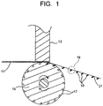
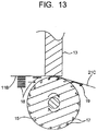
- a substrate of thermoplastic material 11 may be positioned or passed between a vibrating source 13 and a rotating molding roll 15, the roll containing multiple hook-shaped or otherwise shaped cavities 17, along the outer periphery.
- the substrate 11 may include, but not be limited to, film, sheet, web, composite, laminate or other form, or may be portions of a film, sheet, web, laminate or substrate thermoplastic material which may be used as individual fastening tabs, for instance on a disposable infant diaper.
- touch fasteners may be attached to a "side tab" that the consumer uses to secure a diaper to the infant.
- These tabs may be constructed with a piece of extensible material to allow the tab to stretch and flex when attached or when the infant moves.
- the present disclosure further contemplates the use of pre-formed film, sheet, web, composite, laminate, etc. as a substrate material.
- the vibrating source 13 is positioned in close proximity to the outer surface of the rotating molding roll 15 and in contact with the substrate of thermoplastic material 11 being processed.
- the source of vibration 13 may include, but not be limited to, a vibrating ultrasonic horn, for example. These horns may be made from metals such as aluminum or titanium and are sold in the United States by companies such as Branson Ultrasonics, Dukane or Sonitek, and in Europe by a company such as Mecasonics.
- the source of vibration 13 may be vibrated in frequencies between about 50 Hz to about 50 kHz, as required.
- Other sources of vibration energy may be utilized, including but not limited to, a rotating eccentric roller, high pressure sound waves or other mechanical and/or electromechanical or acoustical forms of vibration energy. Such energy may therefore be transferred to a substrate and assist in the formation of the projection herein.
- thermoplastic material substrate 11 in contact with the molding roll 15 and vibrating source 13 may be softened by the vibration energy from the source and a desired portion of the thermoplastic material caused to enter into the cavities 17 of the molding roll forming hook-shaped or otherwise shaped elements or projections 19 on the front surface of the film or sheet 21 as the roll turns.
- This process may be referred to as rotary forming.
- Reference to a force may be understood as applying a requisite amount of pressure to the thermoplastic material to assist in its entry and fill-out of the cavities 17.
- the thermoplastic sheet 21 may function as a carrying strip for the hooks 19.
- Thermoplastic materials which may be used to produce the hook fasteners may include, but not be limited to, polyamides, polyolefins such as polypropylene and polyethylene, acrylonitrile-butadiene-styrene (ABS), polyester, polycarbonate, polyvinyl chloride (PVC) and blends thereof.
- the thermoplastic materials may also be modified or reinforced with fillers, fibers, flame retardants, colorants, etc.
- thermoplastic material that is immediately adjacent to the vibrating source may not melt and may therefore retain most, if not all, of its' original properties, in other words, not be subjected to a heat history which might detract from its' original properties.
- the molecular orientation of the material entering into the cavities may be maintained, increased or reduced by altering the vibration energies applied
- FIG. 18 is an enlarged cross-sectional view of an exemplary projection 19 protruding from a substrate 21 produced in accordance with an exemplary method of the present disclosure, such as shown in FIG.1 .
- the stem portion 19A of the projection formed from the imposition of vibration energy may substantially maintain its molecular orientation or even increase somewhat as measured by shrinkage after forming or by its tensile strength after vs. before forming.
- the polymeric material prior to entering the cavities, has a tensile strength (TS) in the direction of an orientation plane that is present (e.g. in the machine direction which may be understood as, e.g., the direction of extrusion) of TS 1
- the projections, formed due to exposure to vibration energy may still exhibit a tensile strength (TS 2 ) in a direction of orientation that is at least 50% of TS 1 , or higher (e.g. up to 200%).
- the shrinkage attributable to orientation prior to exposure to vibrational energy is of a given value (S 1 )
- the shrinkage (S 2 ) that may exist after exposure to vibrational energy, in the same direction in the projection may be at least 50% of its original value, or higher (e.g. 150%). That is, S 2 > 0.50(S 1 ).
- Reference to shrinkage herein may be understood as the loss in dimension that will occur when the substrate is heated to a temperature above which the orientation will relax and generally disappear. As noted herein, this may be above the glass transition temperature (Tg) for an amorphous polymer or about the melting point (Tm) for a crystalline polymer.
- a substrate that contains little or no orientation may be understood as that situation where the shrinkage is less than or equal to 5.0% in any given direction. It may also be characterized as that situation where the Elmendorf Tear strength in a given machine direction (ET MD ) is approximately equal to the Elmendorf Tear (ET CD ) in a given cross direction, with respect to a given substrate. Cross-direction may be understood as that direction, e.g., that is transverse to a machined direction (MD). That is, ET MD is within about +/- 20% of ET CD .
- Elmendorf tear strength may be measured by ASTM D1922 and may be understood as the average force required to propagate tearing through a length of the substrate at issue.
- the application of vibrational energy and the formation of a projection for mechanical engagement may provide a projection that includes orientation, relative to the generally non-orientated substrate from which it was formed.
- the orientation in such projection may be such that it includes shrinkage in a given direction of greater than 5.0%.
- a substrate that has biaxial orientation may be understood as that situation where there is orientation in both the machine and cross-directions.
- the machine and cross-direction may indicate relatively uniform shrinkage values of greater than 5.0%. It may therefore be appreciated that upon formation of a projection for mechanical engagement, the underlying substrate will now substantially retain the biaxial orientation, due to the ability to focus the vibration energy at the surface of the substrate, to form the projection, without substantially disturbing the underlying biaxial orientation present in the substrate.
- FIG. 19 is an example of an enlarged cross-sectional view of an exemplary projection protruding from a layered substrate produced in accordance with an exemplary method of the present disclosure, such as shown in FIG. 1 .
- a second material 121 has been joined to the substrate material 21 and through processing according to the present disclosure, projection 19 is formed.
- a portion 122 of the second material 121 may extend into the body or stem 19A of the projection 19 and may provide enhanced properties to the projection.
- portion 122, which is formed form substrate material 121 may have a different Shore Hardness value than the Shore Hardness value that is associated with substrate material 21.
- the fastener elements may be produced from one or more colors and the strip-like base may be of a different color(s).
- the fastening elements or the strip-like material may be formed to be transparent.
- the present disclosure allows the substrate material to retain such desirable properties as molecular orientation, multicolored layers or composite structures by softening the polymer and forming it into the desired shape using vibratory energy, thereby also minimizing the thermal history of the polymer(s) processed.
- a means for cooling may be provided on or adjacent the molding roll 15 and the formed product, a strip 21 of polymer including a plurality of hook-type projections 19, may be peeled from the molding roll. Cooling may be accomplished by, for instance, cooling the molding roll externally and/or internally, cooling the vibrating source internally and/or externally and/or cooling the thermoplastic material directly and/or indirectly through the use of liquid, gas, air or other means.
- an after-burst of ultrasonic energy may be applied during or after cooling has taken place to aid in "decoupling" the projections from the mold or horn. This may be particularly useful when the projections are formed in the surface of the source of energy, i.e. the horn.
- FIG. 12 One example of a process for providing projections on a substrate which may be used as one of the mating portions in a touch fastening system is shown in FIG. 12 .
- a molding roll or other shape, may be provided containing multiple hook-shaped or otherwise shaped cavities, arranged along the outer periphery of the molding roll, the cavities capable of forming projections conforming to the shape of the cavities.
- a source of vibration energy may be provided, for instance an ultrasonic horn or roll.
- a substrate material may be provided (Block 300 ), in, for instance, film, sheet, web, laminate, composite, etc., form and the substrate positioned (Block 400 ) between the molding roll and source of vibration.
- Power may be applied (Block 500 ) to the source of vibration to selectively soften the substrate material and allow material into the cavities in the molding roll, forming projections.
- the molding roll may be smooth and the cavities for forming the projections may be formed into the surface of the source of vibration as depicted in FIGS. 5 , 7 and 8 .
- the projections, and substrate may be cooled and the substrate including projections extending from the surface thereof may be stripped from the molding roll to form a strip for use in a touch fastener system. Cooling make take place between the molding roll and the source of vibration, in the molding roll or on the substrate after release from the roll. The projections may subsequently be post-formed into a desired shape.
- the cavities for forming the projections may be also be formed in the surface of a rotating horn (see FIGS. 4-8 ).
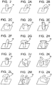
- cavities may be chosen to produce projections having other shapes which may function as the "hook" portion of a touch fastener system including, but not limited to, straight pins, angled pins, tapered pins, mushroom headed pins and curved pins, as well as elements with varying cross-sections such as, but not limited to round, oval, square, rectangular, trapezoidal, cross, multi-lobed, grappling hook, multi-limbed or combinations of these.
- the projections may have a solid core or may be in hollow form such as tubular. Examples of some of these shapes are shown in FIG. 2A-N . For instance, FIG. 2G is an example of a multi-lobed projection, FIG.
- FIG. 2I is an example of tubular
- FIG. 2J is an example of cross-shaped
- FIG. 2K is an example of Y-shaped
- FIG. 2L is an example of a grappling hook
- FIG. 2M is an example of multi-limbed.
- FIG. 2J is an example of a four-limbed projection
- FIG. 2K is an example of a three-limbed projection
- projections may include additional limbs, such as 5, 6, 7, 8, etc.
- Such projections may vary in height, thickness and in the angle that they may project from the carrying strip 21 or substrate.
- the projections may be formed of a uniform height or may vary in height.
- the surfaces of the vibrating source 13 may be shaped so as to increase the length of time thermoplastic materials may be subjected to the vibration energy or to otherwise improve the properties and/or performance of the process.
- FIG. 3 shows one example of one type of a modified surface for a vibrating source 13A wherein a portion of the surface 12A of the vibrating source 13A has been provided which is complementary in shape to the surface of the molding roll 15. Also, in FIG. 3 , a portion 12 of the vibrating surface has been modified, in this example as a complex curved surface, to allow thicker thermoplastic materials 11A to pass between the vibrating source 13A and the molding roll 15. Shaping of the vibrating source 13A may also be used to reduce distortion of the finished product and to aid in guiding the thermoplastic material substrate 11 between the vibrating source 13 and the rotating molding roll 15.
- the source of vibration may be a roll which may include cavities for forming the projections and a rotating roll 22 may be positioned so as to force the softened thermoplastic into the cavities.
- the rotating vibration source 20 may contain multiple hook-shaped or otherwise shaped cavities 17 along its' outer periphery and may be used in place of the stationary vibrating source 13, 13A (as shown in FIGS. 1 and 3 ) and positioned in close proximity to the rotating roll 22.
- the vibrating source 20 may be a rotary ultrasonic horn. These horns may be made from, for instance, titanium and are sold in the United States by Branson Ultrasonics and in Europe by Mecasonics.
- a roll with a patterned surface may be substituted for the smooth roll if patterning the back surface 24 of the product is desired. Patterning the back of the product to simulate woven structures or leather materials or other designs may serve to enhance the aesthetics and/or functionality of the product. In some cases, a patterned surface may be designed on one or both rolls to form apertures in the base material thereby making the fastener breathable or permeable.
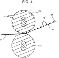
- a rotating vibration source 20 containing multiple hook-shaped or otherwise shaped cavities 17, along its outer periphery as shown in FIG. 4 may be positioned in close proximity to a non-rotating stationary platen 26.
- the platen surface 28 may be smooth or patterned if patterning the back surface of the product is desired.
- FIG. 6 shows an exemplary embodiment of another type of modified stationary platen 30 in combination with a rotary vibration source 20.
- one surface 32 of the platen has been modified, in this example as a complex curved surface, to allow thicker thermoplastic materials (substrates) to pass between the vibrating source 20 and the modified stationary platen 30.
- Reference numeral 32A indicates an area where the surface of the platen 30 is complementary in shape to the shape of the surface of the rotary vibration source 20.
- Shaping of the modified stationary platen 30 may also be used to reduce distortion of the finished product and aid in guiding the thermoplastic material substrate 11A between the rotating vibration source 20 and the stationary platen 30.
- the platen surface 32 may be smooth or patterned if patterning the back surface of the product is desired.
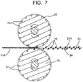
- a rotating vibration source 20 containing multiple hook-shaped or otherwise shaped cavities 17 along its outer periphery may be combined with a rotating molding roll 15 (such as is shown in FIG. 1 ) to produce a polymeric strip having projections on both the front and back side of the sheet 21A.
- the rotating vibration source 20 may be positioned in close proximity to the outer surface of the rotating molding roll 15 and both rolls may contain multiple hook-shaped or otherwise shaped cavities 17 , along their outer peripheries. As shown, this may allow for the production of products with hook-shaped or otherwise shaped elements 19 on the front surface 23 and back surface 24 of the carrying strip 21A simultaneously.
- a rotating vibration source 20 containing multiple hook shaped or otherwise shaped cavities 17, along its outer periphery may be positioned in close proximity to another rotating vibration source 20A containing multiple hook shaped or otherwise shaped cavities 7 , along its' outer periphery. This would allow for the production of products with hook-shaped or otherwise shaped elements 19 on the front surface 23 and back surface 24 of the carrying strip 21A simultaneously.
- FIG. 9 depicts the use of two vibrating stationary sources 13 in close proximity to a rotating molding roll 15 containing multiple hook-shaped or otherwise shaped cavities 17, along the outer periphery of the molding roll 15.
- the process and apparatus according to the present disclosure is suitable for forming a product having projections which may function as hook fasteners or projecting elements having other shapes in touch fastening systems on one or more surfaces of a strip of thermoplastic material substrate, the substrate comprising film, sheet, web, composite, laminate or other form, or from portions thereof.
- the substrate may include a cellular structure, such as a foamed polymer, for example, or be a molecularly oriented film or a composite that may, for example, include a fibrous reinforcement.
- the projections may have a variety of shapes, lengths and dimensions. The projections may be formed from one or more of the materials making up the multilayered film or substrate sheet or portions of such.
- the substrate may comprise a thermoset polymer.
- the substrate upon which the projections are formed may include continuous or intermittent layers of materials and combinations thereof.
- projections may be formed on an intermittent web, to produce diaper closure tabs, possibly inline with a diaper manufacturing machine.
- projections may be formed in their final shape or produced partially shaped and post-formed to obtain their final geometry, for instance, a straight pin that may be reshaped into a hook shape, or a straight pin that may be blunted into a mushroom shape in a subsequent processing step or a deformed hook that may be post-formed into a hook capable of functioning as a fastening element.
- the projections as formed herein may provide a means of fastening, either temporary or permanent, by engaging with a material having loop elements (e.g. structures that will mechanically engage a projection such as a hook), or engaging to screen-like materials, open-celled foam-like materials or a material having similar or mating projections (for instance, hooks, mushrooms, etc.)
- a material having loop elements e.g. structures that will mechanically engage a projection such as a hook
- engaging to screen-like materials, open-celled foam-like materials or a material having similar or mating projections for instance, hooks, mushrooms, etc.
- the projections of the present disclosure may be formed intermittently on a substrate by turning the source(s) of vibration on and off as desired or by intermittently altering the position and/or contacting force and/or vibration frequency of the vibrating source. For example, one may move an ultrasonic horn or other vibration source up and down intermittently while a web passes through the process to intermittently form projections on a substrate.
- projections may be formed in a desired pattern, and the pattern may be varied during the in-line processing of the substrate. Accordingly, the projections may be of uniform height or multilevel height depending on the conditions of operation of the apparatus.
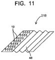
- FIG. 10A is a schematic front view showing an exemplary embodiment of a configuration of apparatus wherein the molding roll 42 includes a portion 44 of the surface including cavities to form projecting elements and the vibrating source 40 and molding roll 42 each include complementary portions of their surfaces 46, 46A configured to form a creped area.
- FIG. 10B is a schematic cross-sectional side view of FIG. 10A .
- FIG. 11 depicts an example of a product that may be produced from the configuration depicted in FIG. 10A . In this example, hook type elements 19 have been formed adjacent to creped areas 48 on a web 21B.
- creped portion and the fastening portion may thus be formed into a web material simultaneously such that an extendable diaper fastening tab is formed.
- Either of the surfaces 46, 46A may be configured to form a crepe area or one of the surfaces may comprise a compliant material, such as rubber or an elastomer, which under nip pressure will conform to the opposing surface configuration.
- Reference to crepe may be understood to mean a quality in a web imparted by embossing to give a wavy surface such as a crimp in a web.
- Reference to a wavy surface may be understood to mean a surface that rises and falls in relative position.
- projections may be formed while simultaneously attaching them to an extensible or non-extensible web.
- an extensible material or non-extensible material 11B may be fed between a rotating molding roll 15 and a stationary source of vibration 13 (or rotating source of vibration or other configurations of mold and vibration sources for forming projections, as disclosed herein) (see, for instance, FIGS. 1 , 3-9 , 10A and 10B ) .
- the vibration source 13 may be positioned in close proximity to the mold 15, but far enough away to avoid melting or deforming the extensible material or non-extensible material 11B.
- Pieces of thermoplastic or thermosettable materials 18 materials may be intermittently fed between one or more sides of the extensible material or non-extensible material 11B and the vibration source 13. When the pieces pass between the vibration source 13 and the mold roll 15, for example, the additional thickness may cause the thermoplastic or thermosettable material to be forced into the cavities 17.
- a pattern of projections may be formed by passing a pre-perforated or pre-die cut masking material between the substrate (film, sheet, composite, etc.) and molding roll thereby selectively covering areas of the molding roll and providing an intermittent pattern of projections.
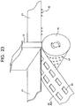
- the mask may be removed ( FIG. 22 ) or may be bonded to the substrate ( FIG. 21 ) if desired. Accordingly, variations in patterns may be provided relatively easily without having to change the configuration of the molding roll.
- the die cutting, or other formation of a mask may be done in-line or off-line.
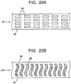
- FIGS. 20A and 20B illustrate examples of masking materials for such a purpose.
- FIG. 20A is a top view of a mask 80 comprising a sheet of material 82, such as paper, metal, film, fabric, etc. which has one or more openings 84 formed therein.
- FIG. 21 illustrates the apparatus and process of FIG. 1 wherein a mask 80 in sheet form is fed into the nip between the vibration source 13 and the molding roll 15 such that portions of the mask cover selected cavities 17 in the molding roll and an intermittent pattern of projections 19 are formed through the openings 84 on the surface of the formed substrate 21.
- FIG. 22 illustrates a similar process where the mask 80 may be separated from the substrate 21 and not become part of the finished product.
- FIG. 23 is a perspective view of the apparatus and process of FIG. 21 .
- FIG. 24 illustrates another apparatus and process similar to FIG. 1 wherein a material 90 in sheet form (such as a foam, non-woven web, etc.) is laminated to a substrate material 11 and fed into the nip between the vibration source 13 and the molding roll 15. Portions 100 of the molding roll 15 may be removed to allow portions of the material 90 to provide an intermittent pattern of projections 19 and to further allow the material 90A to surround the discrete areas of projections 19 and act as a gasket. Accordingly, as shown an intermittent pattern of projections 19 are formed like islands between the areas of material 90A.
- the thermoplastic material of layer 11 impregnates the material 90 when the projections 19 are formed.
- the height of the projections 19 may be less than the height of the material 90A such that the projections do not engage a mating fastening system element and premature engagement is substantially prevented. In an application such as a fastening tab for a diaper this may also provide protection from the projections encountering the baby's skin.
- projections may be formed through openings in covering layers of material by passing multiple layers of material between a molding roll and vibration source where the covering layer may include holes that align with the pattern of cavities in one or more of the rolls, or where porous materials, such as textiles, may provide openings for the substrate material to be forced through and into the cavities in the roll(s), or where the strength of the covering layer is sufficiently weak such that a substrate material may burst through the covering material and into the cavities of the mold.
- FIG.20B illustrates another type of mask 80A made from a porous substrate material 88 , such as screen, non-woven, open-cell foam, etc. that has been covered by, for instance a coating or by laminating another material 86 except in areas wherein openings 84 are formed in the coating.
- the porous material 88 is visible through the openings 84 such that projections may be formed therethrough, while the coated areas of the mask act to prevent the formation of projections 19.
- a mask may be applied locally directly to a portion of the surface of the molding roll such as by spraying or dipping a liquid and then drying such. This coating may then prevent the formation of projections in selected areas of the substrate.
- the mask may be reused or peeled off and reapplied.
- thermoplastic substrate/fabric/thermoplastic fabric may be passed between cooperating rolls/vibration sources (see, for instance, FIGS. 7 and 8 ) to provide a pattern of back-to-back projections having a reinforcing layer.
- intermittent cuts or slits or other wise shaped apertures may be produced in the substrate by raising portions of the molding roll surface (or rotary horn surface) to create cuts or very thin portions of the substrate. These modifications to the substrate may serve to make the fastening strip softer and/or stretchable and/or breathable.
- the process and apparatus as described herein may provide advantages over an extrusion/molding process as relatively less heating and cooling energy may be consumed since only the material used to form the projections may be heated and cooled. Further, multiple colors may be provided by the choice of substrate material and a broad variety of properties may be obtained through the selection of substrate materials, including but not limited to, molecularly oriented substrates or composite substrates. Materials that have printed patterns, logos, etc., may be used as substrates and thereby have projections formed into one or more of their surfaces allowing the printed patterns, etc. to remain legible. Startup time for the process may be relatively fast and the process may be started and stopped at will, eliminating the need for complex and costly automated transfer winders, as are often required in continuous extrusion processes. Finally, floor space may be reduced substantially.
- Touch fasteners are often adhered to various thermoplastic objects.
- One such application involves the attachment of touch fasteners to automotive door panels and interior headliner panels.
- the materials chosen for use as touch fasteners (polyamides, polyolefins, etc.) often make adhesive bonding difficult, expensive and a common source of failure. It is contemplated that a version of the process and apparatus described herein may eliminate or reduce the need for adhesives to bond fasteners to base materials as the hook-type fasteners (projections) may be formed as part of or formed onto the surface of such base materials.
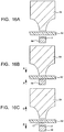
- FIGS. 14A , B and C illustrate a process where an ultrasonic horn 54 may have a vibrating surface 50 which may be constructed with cavities 17 located thereupon ( FIG. 14A ) .
- the ultrasonic horn 54 may be pressed (arrow A ) against a thermoplastic object 52 (for instance, a door panel or headliner substrate for a vehicle) and vibration energy applied ( FIG. 14B ), selectively softening the thermoplastic material and forcing some of the thermoplastic material 52 into the cavities 17. The vibration energy may then be stopped, the thermoplastic material allowed to cool and the ultrasonic horn retracted (arrow B, FIG. 14C ) freeing the newly formed projections 19 from the cavities 17 and providing a plastic object having a surface with a local pattern of projections for attachment formed thereupon.
- a thermoplastic object 52 for instance, a door panel or headliner substrate for a vehicle
- vibration energy applied FIG. 14B
- the vibration energy may then be stopped, the thermoplastic material allowed to cool and the ultrasonic horn retracted (arrow B, FIG. 14C ) freeing the newly formed projections 19 from the cavities 17 and providing a plastic object having a surface with a local pattern of projections for attachment formed thereupon.
- an after-burst of ultrasonic energy may be applied during or after cooling has taken place to aid in "decoupling" the projections from the mold or horn. This may be particularly useful when the projections are formed in the surface of the source of energy, i.e. the horn. It is contemplated that a removable or replaceable horn tip may be used to allow relatively rapid changing of the pattern of projections.
- FIGS. 15A , B and C illustrate similarly that various thermoplastic or thermosettable materials 60 may be positioned between the ultrasonic horn 54 and the object 52 ( FIG. 15A ) allowing for the formation of projections 19, fully or partially from the positioned material 60 ( FIG. 15B ). In this manner, the projections 19 may be formed from a second material 60 and through the vibration process that material may be bonded to the object 52 ( FIG. 15C ). It may be appreciated that this will have particular utility in that situation where the object 52 is an automotive trim panel, which may be understood as a thermoplastic and/or thermoset door panel, instrument panel, center console, rear close-out panels, headliner, etc.
- the cavities may be provided in a mold-like base 56 and not in the ultrasonic horn 54.
- the thermoplastic object 52 may be positioned ( FIG. 16A ) and held under pressure (arrows A, FIG. 16B ) between the ultrasonic horn and the mold base 56.
- Vibration energy may be applied to the horn ( FIG. 16B ), forcing some material from the object 52 into the cavities 17 of the base. Again, the vibration energy may be stopped, the thermoplastic material allowed to cool and the ultrasonic horn retracted (arrows B ) ( FIG. 16C ) freeing the newly formed projections 19 from the cavities 17 and providing a plastic panel having a surface with a local pattern of projections formed thereupon for attachment thereto.
- FIGS. 17A , B and C illustrate that various thermoplastic or thermosetting materials 60 may be positioned between the object 52 requiring the projections 19 and the mold-like base 56 containing the cavities 17 ( FIG. 17A ) .
- the projections may be formed from the material 60 by forcing the horn 54 and mold 56 together around the object 52 and material 60 and applying vibration energy (arrows A, FIG. 17B ). Again, the vibration energy may be stopped, the thermoplastic material allowed to cool and the ultrasonic horn retracted (arrows B ) ( FIG. 17C ) freeing the newly formed projections 19 from the cavities 17 and providing a plastic panel having a surface with a local pattern of projections formed thereupon, the projections of a different material than the object 52.
- the process and apparatus described herein may greatly reduce the complexity of insert molding hook type materials into larger molded objects as different types of materials may be fed in layers to the apparatus and the projections formed on or through one or more of the layers. Materials for a portion of the substrate layer or for the projections may thus be different from the substrate materials.
- the use of an ultrasonic horn or other source of vibration energy and the use of a mold-like base as disclosed herein to form projections on objects in a discontinuous or intermittent process or to locally form a pattern of projections on the surface of an object may provide relatively lower capital and space requirements as well as a very flexible process capable of being easily moved. It is contemplated that all of the features disclosed regarding the continuous or semi-continuous process herein also may apply to the local application of projections on an object.
- the projections disclosed herein for use as elements in a touch fastening system may be produced in a relatively wide range of sizes and densities to provide a wide range of fastening or holding strength. While not being held to any particular limits, it is contemplated that the height of such projections may range from less than about 10 microns to greater than about 5 mm.
Landscapes
- Engineering & Computer Science (AREA)
- Mechanical Engineering (AREA)
- Slide Fasteners, Snap Fasteners, And Hook Fasteners (AREA)
- Absorbent Articles And Supports Therefor (AREA)
- Shaping Of Tube Ends By Bending Or Straightening (AREA)
- Casting Or Compression Moulding Of Plastics Or The Like (AREA)
Claims (16)
- Procédé de formation de saillies sur un substrat, comprenant :la fourniture d'un moule (15, 42, 56) ayant une surface extérieure,la fourniture d'un matériau de substrat (11, 21, 52) ayant une surface ;la fourniture d'un dispositif (13, 20, 40, 54) en tant que source d'énergie de vibration ;dans lequel l'un dudit moule (15, 42, 56) et dudit dispositif (13, 20, 40, 54), ou les deux, contient une pluralité de cavités (17), lesdites cavités (17) ayant une forme ;le positionnement dudit matériau de substrat (11, 21, 52) entre ledit moule (15, 42, 56) et ledit dispositif (13, 20, 40, 54) ;l'application de puissance audit dispositif (13, 20, 40, 54) pour ramollir le matériau avec de l'énergie de vibration, dans lequel une portion dudit matériau de substrat (11, 21, 52) pénètre dans lesdites cavités (17) dans la surface dudit moule (15, 42, 56) et/ou dudit dispositif (13, 20, 40, 54) ; etla formation de saillies (19) sur au moins une portion de ladite surface dudit matériau de substrat (11, 21, 52),dans lequel lesdites cavités (17) sont mises en forme pour former des saillies (19) ayant une forme comme une ou plusieurs parmi des crochets, des champignons, des broches coudées, des broches courbes, un grappin, à branches multiples, en forme de croix, en forme de Y et à plusieurs lobes, chacune ayant des sections transversales qui sont ronde, ovale, carrée, rectangulaire, trapézoïdale, pleine, creuse, et des combinaisons de celles-ci.
- Procédé selon la revendication 1 dans lequel ledit matériau de substrat (11, 21, 52) est forcé dans lesdites cavités (17) par la source d'énergie de vibration.
- Procédé selon l'une quelconque des revendications 1 ou 2 dans lequel ledit substrat formé (21B) inclut en outre une zone crêpée (48) produite à partir d'une portion d'un ou des deux parmi ledit moule (42) et ledit dispositif (40) ayant une surface ondulée (46, 46A).
- Procédé selon l'une quelconque des revendications 1 à 3 dans lequel ladite application de puissance audit dispositif (13, 20, 40, 54) est intermittente.
- Procédé selon l'une quelconque des revendications 1 à 4 dans lequel ledit matériau de substrat (11, 21, 52) comprend un matériau thermoplastique et/ou thermodurcissable.
- Procédé selon l'une quelconque des revendications 1 à 5, dans lequel ladite énergie de vibration est mécanique ou électromécanique ou acoustique.
- Procédé selon l'une quelconque des revendications 1 à 6, dans lequel ledit matériau de substrat (11, 21, 52) pénètre dans lesdites cavités (17) dans ladite surface dudit moule (15, 42, 56) en formant des saillies (19) et une portion dudit substrat (11, 21, 52) sert de bande de support pour lesdites saillies (19).
- Procédé selon l'une quelconque des revendications 1 à 7, dans lequel ledit substrat (11, 21, 52) comprend un stratifié et inclut une première couche qui inclut une ou plusieurs ouvertures qui exposent une surface d'une seconde couche, et lesdites saillies (19) sont formées sur ladite surface de ladite seconde couche.
- Procédé selon l'une quelconque des revendications 1 à 8, dans lequel la fourniture d'un matériau de substrat (11, 21, 52) comprend la fourniture d'un film, d'une feuille, d'une bande, d'un composite, d'un stratifié, d'une mousse, d'un matériau non-tissé, d'un matériau plastique renforcé par des fibres, d'un matériau thermoplastique et/ou thermodurcissable.
- Procédé selon la revendication 9, dans lequel ledit substrat (11, 21, 52) comprend un stratifié comprenant des couches continues et/ou intermittente de différents matériaux incluant de la mousse, un matériau plastique renforcé par des fibres, des matériaux thermoplastiques ou thermodurcissables orientés.
- Procédé selon l'une quelconque des revendications 1 à 10, dans lequel de l'énergie de vibration est appliquée auxdites saillies (19) pour aider à supprimer lesdites saillies (19) à partir desdites cavités (17).
- Procédé selon l'une quelconque des revendications 1 à 11, dans lequel un second matériau thermoplastique est amené à passer entre ledit matériau de substrat (11, 21, 52) et ledit moule (15, 42, 56) ou ledit dispositif (13, 20, 40, 54), et ledit second matériau thermoplastique est exposé à ladite énergie de vibration en amenant ledit second matériau de substrat à venir en adhérence sur ledit matériau de substrat (11, 21, 52).
- Procédé selon la revendication 12, dans lequel ledit second matériau thermoplastique forme au moins une partie desdites saillies (19).
- Procédé selon l'une quelconque des revendications 1 à 13, dans lequel ledit moule comprend un cylindre rotatif et ledit dispositif comprend un cylindre rotatif, dans lequel l'un desdits cylindres, ou les deux, inclut une surface à motif, et la surface à motif forme des ouvertures dans ledit substrat.
- Procédé selon l'une quelconque des revendications 1 à 14, comprenant en outre l'étape consistant à amener un matériau de masquage à passer entre le matériau de substrat (11, 21, 52) et le premier dispositif (13, 20, 40, 54) ou le moule (15, 42, 56), dans lequel le matériau de masquage comprend du papier.
- Procédé selon l'une quelconque des revendications 1 à 15, dans lequel lesdites cavités (17) sont mises en forme pour former des saillies (19) qui ont la forme de broches coudées ayant des sections transversales qui sont rectangulaires.
Priority Applications (1)
| Application Number | Priority Date | Filing Date | Title |
|---|---|---|---|
| PL17178065T PL3243631T3 (pl) | 2009-01-20 | 2010-01-20 | Sposób wytwarzania wypustek na podłożu |
Applications Claiming Priority (3)
| Application Number | Priority Date | Filing Date | Title |
|---|---|---|---|
| US14588309P | 2009-01-20 | 2009-01-20 | |
| EP10733813.9A EP2379308B1 (fr) | 2009-01-20 | 2010-01-20 | Procédé et appareil de production de fermetures à crochets |
| PCT/US2010/021512 WO2010085492A1 (fr) | 2009-01-20 | 2010-01-20 | Procédé et appareil de production de fermetures à crochets |
Related Parent Applications (1)
| Application Number | Title | Priority Date | Filing Date |
|---|---|---|---|
| EP10733813.9A Division EP2379308B1 (fr) | 2009-01-20 | 2010-01-20 | Procédé et appareil de production de fermetures à crochets |
Publications (2)
| Publication Number | Publication Date |
|---|---|
| EP3243631A1 EP3243631A1 (fr) | 2017-11-15 |
| EP3243631B1 true EP3243631B1 (fr) | 2019-10-23 |
Family
ID=42335774
Family Applications (3)
| Application Number | Title | Priority Date | Filing Date |
|---|---|---|---|
| EP10733813.9A Active EP2379308B1 (fr) | 2009-01-20 | 2010-01-20 | Procédé et appareil de production de fermetures à crochets |
| EP17178065.3A Active EP3243631B1 (fr) | 2009-01-20 | 2010-01-20 | Procédé de production de projections sur un substrat |
| EP17178063.8A Pending EP3243630A1 (fr) | 2009-01-20 | 2010-01-20 | Procédé et appareil de production de fixations à crochet |
Family Applications Before (1)
| Application Number | Title | Priority Date | Filing Date |
|---|---|---|---|
| EP10733813.9A Active EP2379308B1 (fr) | 2009-01-20 | 2010-01-20 | Procédé et appareil de production de fermetures à crochets |
Family Applications After (1)
| Application Number | Title | Priority Date | Filing Date |
|---|---|---|---|
| EP17178063.8A Pending EP3243630A1 (fr) | 2009-01-20 | 2010-01-20 | Procédé et appareil de production de fixations à crochet |
Country Status (13)
| Country | Link |
|---|---|
| US (3) | US8784722B2 (fr) |
| EP (3) | EP2379308B1 (fr) |
| JP (3) | JP5792072B2 (fr) |
| KR (2) | KR101805341B1 (fr) |
| CN (2) | CN102341228A (fr) |
| AU (2) | AU2010206837B2 (fr) |
| CA (1) | CA2749929C (fr) |
| ES (2) | ES2767739T3 (fr) |
| HK (1) | HK1245194A1 (fr) |
| MX (2) | MX2011007648A (fr) |
| PL (2) | PL3243631T3 (fr) |
| TW (2) | TWI511865B (fr) |
| WO (1) | WO2010085492A1 (fr) |
Families Citing this family (53)
| Publication number | Priority date | Publication date | Assignee | Title |
|---|---|---|---|---|
| EP2379308B1 (fr) | 2009-01-20 | 2017-06-28 | Gerald Rocha | Procédé et appareil de production de fermetures à crochets |
| ES2592683T3 (es) | 2010-07-16 | 2016-12-01 | Gerald Rocha | Tira de fijador por contacto dimensionalmente flexible |
| DE102011107542A1 (de) * | 2011-07-15 | 2013-01-17 | Faurecia Innenraum Systeme Gmbh | Verfahren und Werkzeug zum Einbringen einer Dekornaht |
| TWI499385B (zh) * | 2012-09-14 | 2015-09-11 | Taiwan Paiho Ltd | Velcro Manufacturing Method and Velcro |
| US9918525B2 (en) * | 2013-02-22 | 2018-03-20 | Velcro BVBA | Touch fastener structures |
| US9649792B2 (en) * | 2013-10-15 | 2017-05-16 | Velcro BVBA | Forming longitudinally pleated products |
| KR101889641B1 (ko) * | 2014-07-03 | 2018-08-17 | 와이케이케이 가부시끼가이샤 | 성형면 파스너 및 성형면 파스너의 제조 방법 |
| JP6503179B2 (ja) * | 2014-11-07 | 2019-04-17 | Ykk株式会社 | 面ファスナーの製造方法、及び面ファスナー |
| CN107635747B (zh) | 2015-03-16 | 2020-10-20 | 杰拉尔德·罗查 | 接触紧固件及其形成方法 |
| US10016022B2 (en) * | 2015-10-07 | 2018-07-10 | Ykk Corporation | Hook fastener and methods for manufacturing same |
| TWI555477B (zh) * | 2015-12-03 | 2016-11-01 | Taiwan Paiho Ltd | Mushroom Head Shot Hook and Velcro with the Mushroom Head Shot |
| CN108471844B (zh) | 2015-12-24 | 2020-11-06 | Ykk株式会社 | 成形面连接件、成形面连接件的制造方法、以及成形装置 |
| US11219285B2 (en) | 2015-12-24 | 2022-01-11 | Ykk Corporation | Molded surface fastener manufacturing method |
| DE102016206296B4 (de) * | 2016-04-14 | 2024-05-02 | Airbus Operations Gmbh | Verbindungssystem, Verbindungsanordnung und Verfahren |
| CN106113479A (zh) * | 2016-06-17 | 2016-11-16 | 上海交通大学 | 一种聚合物表面微纳米结构卷对卷热辊压印成型方法 |
| WO2018006947A1 (fr) * | 2016-07-05 | 2018-01-11 | Sca Hygiene Products Ab | Unité de conditionnement pour articles d'hygiène et procédé de formation d'une unité de conditionnement |
| EP3481355B1 (fr) | 2016-07-05 | 2020-08-19 | Essity Hygiene And Health Aktiebolag | Article absorbant ayant un système de fixation amélioré et procédé de fabrication d'un tel article absorbant |
| US10722003B2 (en) * | 2016-11-23 | 2020-07-28 | Velcro BVBA | Touch fastener |
| WO2018124992A1 (fr) | 2016-12-29 | 2018-07-05 | Hayat Kimya San. A. Ş. | Procédé et appareil de production de fermetures à crochets |
| CN110225708B (zh) * | 2017-02-10 | 2022-02-22 | 可乐丽粘贴扣带株式会社 | 固定带、固定方法及固定带构件 |
| JP6794082B2 (ja) * | 2017-02-15 | 2020-12-02 | Ykk株式会社 | 成形面ファスナー及び成形面ファスナーの製造方法、並びに成形装置 |
| EP3981569A1 (fr) | 2017-12-21 | 2022-04-13 | Velcro IP Holdings LLC | Moulage de résine pour former des structures continues |
| CN111511320A (zh) * | 2017-12-22 | 2020-08-07 | 易希提卫生与保健公司 | 吸收性物品和制造吸收性物品的方法 |
| PL3727263T3 (pl) | 2017-12-22 | 2023-08-14 | Essity Hygiene And Health Aktiebolag | Wyrób chłonny i sposób jego wytwarzania |
| KR102039264B1 (ko) | 2018-07-04 | 2019-10-31 | 정창호 | 훅과 루프 파스너 제조용 편직기의 위사 가이드바 듀얼 구동장치 |
| EP3836876B1 (fr) | 2018-08-14 | 2023-11-29 | The Procter & Gamble Company | Éléments de fixation profilés et articles absorbants équipés de ceux-ci |
| WO2020041271A1 (fr) | 2018-08-21 | 2020-02-27 | The Procter & Gamble Company | Systèmes de fixation comprenant des substrats non tissés ayant des crochets formés d'un seul tenant sur ceux-ci |
| CN109589209A (zh) * | 2018-11-29 | 2019-04-09 | 3M创新有限公司 | 一种搭扣条带及其制造方法 |
| US11576822B2 (en) * | 2019-09-17 | 2023-02-14 | The Procter & Gamble Company | Apparatuses and methods for making absorbent articles |
| US20210145660A1 (en) | 2019-11-15 | 2021-05-20 | The Procter & Gamble Company | Tape-type absorbent article with belt structure |
| US11801168B2 (en) | 2019-11-15 | 2023-10-31 | The Procter And Gamble Company | Tape-type absorbent article with belt structure |
| USD970725S1 (en) | 2019-11-15 | 2022-11-22 | The Procter & Gamble Company | Absorbent article component |
| US11793685B2 (en) | 2019-11-15 | 2023-10-24 | The Procter And Gamble Company | Absorbent article having fastening system |
| WO2021163255A1 (fr) | 2020-02-13 | 2021-08-19 | The Procter & Gamble Company | Article absorbant comprenant un système de fixation |
| EP4103120A1 (fr) | 2020-02-13 | 2022-12-21 | The Procter & Gamble Company | Article absorbant avec système de fixation |
| CN115052572B (zh) | 2020-02-13 | 2024-03-22 | 宝洁公司 | 具有扣紧系统的吸收制品 |
| EP4164572A1 (fr) * | 2020-06-12 | 2023-04-19 | The Procter & Gamble Company | Article absorbant avec système de fixation |
| EP4225239A1 (fr) * | 2020-10-06 | 2023-08-16 | The Procter & Gamble Company | Procédés de fabrication de formations de saillies de surface |
| EP4225240A1 (fr) * | 2020-10-06 | 2023-08-16 | The Procter & Gamble Company | Procédés de fabrication de formations en saillie de surface |
| EP4059482A1 (fr) * | 2021-03-19 | 2022-09-21 | Fameccanica.Data S.p.A. | Stratifié élastique continu extensible transversalement et son procédé de fabrication |
| EP4059483A1 (fr) * | 2021-03-19 | 2022-09-21 | Fameccanica.Data S.p.A. | Stratifié élastique continu extensible transversalement et son procédé de fabrication |
| US20220386746A1 (en) * | 2021-06-04 | 2022-12-08 | Yi-Wen Tang | Fastening strap |
| EP4108220A1 (fr) | 2021-06-24 | 2022-12-28 | Fameccanica.Data S.p.A. | Article sanitaire absorbant et son procédé de production |
| EP4194357A1 (fr) | 2021-12-10 | 2023-06-14 | Fameccanica.Data S.p.A. | Bande de fermeture à glissière pour un sachet souple et procédé et appareil de fabrication de sachets souples refermables |
| EP4194356A1 (fr) | 2021-12-10 | 2023-06-14 | Fameccanica.Data S.p.A. | Sac souple refermable et procédé et appareil de fabrication de sacs souples refermables |
| WO2023147446A1 (fr) | 2022-01-31 | 2023-08-03 | The Procter & Gamble Company | Article absorbant ayant un système de fixation |
| US20230330630A1 (en) | 2022-04-18 | 2023-10-19 | The Procter & Gamble Company | Cooling methods for ultrasonic forming and bonding of polymeric webs |
| EP4265399A1 (fr) | 2022-04-18 | 2023-10-25 | The Procter & Gamble Company | Procédés de refroidissement pour la formation et la liaison par ultrasons de bandes polymères |
| WO2024020924A1 (fr) | 2022-07-28 | 2024-02-01 | The Procter & Gamble Company | Article absorbant jetable avec composant de fixation |
| US20240033140A1 (en) | 2022-07-28 | 2024-02-01 | The Procter & Gamble Company | Absorbent articles with disposal fasteners having integral hook fasteners |
| US20240060905A1 (en) | 2022-08-22 | 2024-02-22 | The Procter & Gamble Company | System and method for quality control inspection of unitary protrusions in a substrate |
| WO2024050101A1 (fr) * | 2022-09-01 | 2024-03-07 | Gerald Rocha | Procédé et appareil de formation ultrasonore améliorée |
| US20240140048A1 (en) | 2022-10-31 | 2024-05-02 | The Procter & Gamble Company | System and method for forming protrusions in a substrate used to manufacture absorbent articles |
Family Cites Families (147)
| Publication number | Priority date | Publication date | Assignee | Title |
|---|---|---|---|---|
| US3128514A (en) | 1959-04-03 | 1964-04-14 | Parker Pen Co | Writing instrument releasable securing means |
| US3192589A (en) | 1960-07-18 | 1965-07-06 | Raymond C Pearson | Separable fastener |
| US3196490A (en) | 1961-11-14 | 1965-07-27 | Velok Ltd | Apparatus for manufacture of a continuous strip of molded plastic product |
| US3182589A (en) | 1962-01-22 | 1965-05-11 | American Screen Process Equip | Printing and drying apparatus |
| US3312583A (en) | 1963-10-02 | 1967-04-04 | James J Rochlis | Apertured and staggered molded pile product |
| US3204646A (en) | 1964-12-11 | 1965-09-07 | Coleman R Chamberlin | Hair curler with crossed gripping bristles |
| US3270408A (en) | 1965-05-04 | 1966-09-06 | Raymond N Nealis | Separable interlocking fasteners and method of making them |
| US3497925A (en) | 1967-07-31 | 1970-03-03 | George C Brumlik | Self-gripping fastening assembly |
| US3541440A (en) | 1967-08-22 | 1970-11-17 | Rca Corp | Use in an automatic testing system of a simulator of an article being tested for testing the testing system |
| US3600918A (en) * | 1968-06-05 | 1971-08-24 | Jerome H Lemelson | Extrusion apparatus and method |
| US3541216A (en) | 1968-08-26 | 1970-11-17 | Chris Craft Ind Inc | Process for making an embossed product |
| FR2079944A5 (en) * | 1970-02-18 | 1971-11-12 | Scotto Jean Pierre | Buttonhole tool-comprising a knife flanked by ultrasonic - welding pads to create reinforcing seams around the hole |
| US3665584A (en) | 1970-11-18 | 1972-05-30 | American Velcro Inc | Method and apparatus for making flexible strips of material having a pile of hook-shaped elements |
| US3927443A (en) | 1971-08-13 | 1975-12-23 | Ingrip Fasteners | Multi-element self-gripping devices with linguiform gripping tabs |
| US3752619A (en) | 1971-11-11 | 1973-08-14 | American Velcro Inc | Production of a continuous molded plastic strip |
| US3762000A (en) | 1971-11-11 | 1973-10-02 | M Menzin | Production of a continuous molded plastic strip |
| US3758657A (en) | 1971-12-01 | 1973-09-11 | American Velcro Inc | Production of a continuous molded plastic strip |
| US3837973A (en) | 1972-07-07 | 1974-09-24 | Toyo Kagaku Kk | Apparatus for continuously producing corrugated plastic board |
| FR2285975A1 (fr) * | 1974-09-26 | 1976-04-23 | Mortreux Bernard | Appareil pour le soudage aux ultrasons de plusieurs feuilles et le complexe ainsi obtenu |
| US4149540A (en) | 1975-07-02 | 1979-04-17 | Velcro Usa Inc. | Separable cinch fastener |
| US4194937A (en) | 1978-10-16 | 1980-03-25 | L. M. Rabinowitz & Co., Inc. | Apparatus for processing hook and eye fasteners |
| US4326903A (en) | 1980-12-05 | 1982-04-27 | Branson Ultrasonics Corporation | Method for securing parts together by ultrasonic energy |
| US4411721A (en) | 1982-02-25 | 1983-10-25 | The Mead Corporation | Apparatus and method for attaching fastener tapes |
| JPS5911803A (ja) | 1982-07-13 | 1984-01-21 | ワイケイケイ株式会社 | ル−プフツクフアスナ−のフツク製造装置 |
| US4775310A (en) | 1984-04-16 | 1988-10-04 | Velcro Industries B.V. | Apparatus for making a separable fastener |
| US4794028A (en) * | 1984-04-16 | 1988-12-27 | Velcro Industries B.V. | Method for continuously producing a multi-hook fastner member and product of the method |
| US4615084A (en) * | 1984-08-21 | 1986-10-07 | Erblok Associates | Multiple hook fastener media and method and system for making |
| US4881997A (en) | 1985-07-17 | 1989-11-21 | Velcro Industries. B.V. | Method for adapting separable fasteners for attachment to other objects |
| JPS62135334A (ja) | 1985-12-10 | 1987-06-18 | Hitachi Maxell Ltd | 光情報記録用デイスク基板の製造方法及びその製造装置 |
| US4811428A (en) | 1987-09-02 | 1989-03-14 | International Paper Company | Washable and disposable bib and fabric for manufacturing same |
| US4980003A (en) | 1988-02-17 | 1990-12-25 | Erblok Associates | Method for producing zigzagged plastic strand and forming into multiple-hook fastener media |
| US5340301A (en) | 1988-08-05 | 1994-08-23 | Northrop Grumman Corporation | Corrugated substructure forming tool |
| US4999067A (en) * | 1989-02-13 | 1991-03-12 | Erblok Associates | Method for making a hermaphrodite hook and loop fasteners |
| DE69015850T2 (de) | 1989-03-24 | 1995-05-24 | Paragon Trade Brande Inc | Wegwerfwindel mit einem wiederverwendbaren Verschlusssystem. |
| JPH0355716U (fr) | 1989-10-03 | 1991-05-29 | ||
| JPH03247306A (ja) | 1990-02-23 | 1991-11-05 | Kuraray Co Ltd | 成形面フアスナー |
| US5110649A (en) | 1990-07-03 | 1992-05-05 | Velcro Industries, B.V. | Separable fasteners for attachment to other objects |
| US5077870A (en) * | 1990-09-21 | 1992-01-07 | Minnesota Mining And Manufacturing Company | Mushroom-type hook strip for a mechanical fastener |
| US5312456A (en) | 1991-01-31 | 1994-05-17 | Carnegie Mellon University | Micromechanical barb and method for making the same |
| US5107626A (en) | 1991-02-06 | 1992-04-28 | Minnesota Mining And Manufacturing Company | Method of providing a patterned surface on a substrate |
| JP3059788B2 (ja) * | 1991-08-06 | 2000-07-04 | 大日本印刷株式会社 | 易開封性袋及びその製造方法 |
| US5231738A (en) | 1991-12-12 | 1993-08-03 | Kuraray Co., Ltd. | Mixed hook/loop separable fastener and process for its production |
| US5614057A (en) | 1992-02-19 | 1997-03-25 | Mim Industries, Inc. | Automatic ultrasonic fusing system |
| JP2756211B2 (ja) | 1992-06-17 | 1998-05-25 | ワイケイケイ株式会社 | 両面に係合片を有する一体成形面ファスナーの製造方法及びその装置 |
| US5919493A (en) * | 1992-10-13 | 1999-07-06 | Ushers, Inc. | Apparatus for producing shaped articles |
| US5325569A (en) * | 1992-10-30 | 1994-07-05 | The Procter & Gamble Company | Refastenable mechanical fastening system having particular viscosity and rheology characteristics |
| TW317223U (en) | 1994-01-13 | 1997-10-01 | Minnesota Mining & Mfg | Abrasive article |
| JP2886455B2 (ja) | 1994-07-08 | 1999-04-26 | ワイケイケイ株式会社 | 一体成形面ファスナーの係着片構造 |
| US5647552A (en) | 1994-09-21 | 1997-07-15 | Fuji Photo Film Co., Ltd. | Photo film cassette |
| US5586371A (en) | 1994-11-08 | 1996-12-24 | The Procter & Gamble Company | Method for manufacturing refastenable fastening systems including a female loop fastening component and the product produced therefrom |
| WO1996014191A1 (fr) | 1994-11-08 | 1996-05-17 | Minnesota Mining And Manufacturing Company | Procede permettant de faire des ouvertures dans des materiaux en feuille mince |
| US5624427A (en) | 1995-01-18 | 1997-04-29 | The Procter & Gamble Company | Female component for refastenable fastening device |
| US5500268A (en) | 1995-01-31 | 1996-03-19 | Aplix, Inc. | Fastener assembly with magnetic side and end seals and method |
| JPH08299032A (ja) | 1995-05-09 | 1996-11-19 | Ykk Kk | 成形面ファスナー |
| US5657516A (en) | 1995-10-12 | 1997-08-19 | Minnesota Mining And Manufacturing Company | Dual structured fastener elements |
| US5725704A (en) * | 1995-12-21 | 1998-03-10 | Davidson Textron, Inc. | Process for the production of a multi-layer composite article having fasteners affixed to a surface thereof and the article produced thereby |
| JPH09199196A (ja) | 1996-01-23 | 1997-07-31 | Alps Electric Co Ltd | フラットケーブルと端子の接続構造 |
| JP3609207B2 (ja) | 1996-05-31 | 2005-01-12 | Ykk株式会社 | 生分解性面ファスナー |
| JP3494529B2 (ja) | 1996-06-06 | 2004-02-09 | Ykk株式会社 | 一体成形面ファスナー |
| JP3461662B2 (ja) | 1996-06-06 | 2003-10-27 | Ykk株式会社 | 一体成形面ファスナー |
| US5879494A (en) * | 1996-09-23 | 1999-03-09 | Minnesota Mining And Manufacturing Company | Method of aperturing thin sheet materials |
| US6054091A (en) | 1996-10-03 | 2000-04-25 | Minnesota Mining And Manufacturing Co. | J hook-type hook strip for a mechanical fastener |
| US5953797A (en) | 1996-10-09 | 1999-09-21 | Velcro Industries B.V. | Hook fasteners and methods of manufacture |
| DE19646318A1 (de) * | 1996-11-09 | 1998-05-14 | Binder Gottlieb Gmbh & Co | Rationelles Verfahren zur Herstellung eines Haftverschlußteils aus thermoplatischem Kunststoff |
| US5981027A (en) | 1996-11-26 | 1999-11-09 | Velcro Industries B.V. | Fastening member with loops and process and machine for producing it |
| JPH10201504A (ja) | 1997-01-20 | 1998-08-04 | Ykk Corp | 一体成形により得られる面ファスナー用係合部材 |
| GB9703130D0 (en) | 1997-02-14 | 1997-04-02 | Renwick Richard | Method of attaching a cleaning pad to a machine |
| US5919492A (en) | 1997-06-13 | 1999-07-06 | Tarr; John | Injection molding system with sequential gate control |
| JPH1146811A (ja) | 1997-08-05 | 1999-02-23 | Ykk Corp | 面ファスナー用雌係合部材とその製造方法 |
| DE19828856C1 (de) | 1998-06-29 | 1999-10-07 | Binder Gottlieb Gmbh & Co | Verfahren zur Herstellung eines Haftverschlußteiles |
| AU8525998A (en) * | 1998-07-27 | 2000-02-21 | Kitsilano Industries Inc. | Building block |
| US6205623B1 (en) | 1998-11-06 | 2001-03-27 | Velcro Industries B.V. | Composite hook and loop fasteners, and products containing them |
| US6248276B1 (en) | 1999-01-15 | 2001-06-19 | Velcro Industries B.V. | Fasteners and methods of making fasteners |
| US6991843B2 (en) * | 1999-01-15 | 2006-01-31 | Velcro Industries B.V. | Fasteners engageable with loops of nonwoven fabrics and with other open structures, and methods and machines for making fasteners |
| JP2000225650A (ja) * | 1999-02-08 | 2000-08-15 | Ykk Corp | 平板状基材表面に起立する合成樹脂製突起物の二次成形装置 |
| US6165298A (en) * | 1999-04-30 | 2000-12-26 | Kimberly-Clark Worldwide, Inc. | Patterned anvil-roll |
| JP2001008712A (ja) | 1999-06-28 | 2001-01-16 | Ykk Corp | 成形面ファスナーの成形装置と成形面ファスナー |
| BR0002371A (pt) * | 1999-06-28 | 2001-01-02 | Ykk Corp | Fecho de superfìcie moldado, aparelho de moldagem e método de moldagem baseado nos mesmos |
| WO2001068019A1 (fr) | 2000-03-14 | 2001-09-20 | Velcro Industries B.V. | Fixation extensible |
| CA2403309A1 (fr) | 2000-03-14 | 2001-09-20 | William Clune | Produits de fixation plies |
| JP2001266417A (ja) | 2000-03-17 | 2001-09-28 | Sony Corp | 転写方法 |
| US6543099B1 (en) | 2000-06-02 | 2003-04-08 | Velcro Industries B.V. | Varying the loop engageability of fastener element arrays |
| US6588073B1 (en) | 2000-08-11 | 2003-07-08 | Kimberly-Clark Worldwide, Inc. | Male fasteners with angled projections |
| DE10056567A1 (de) * | 2000-11-15 | 2002-05-29 | Binder Gottlieb Gmbh & Co | Verfahren zur Herstellung eines Haftverschlußteils |
| DE10102501C2 (de) * | 2001-01-19 | 2003-02-20 | Advanced Design Concepts Gmbh | Oberflächenstrukturierung mittels Ultraschall |
| MXPA03007521A (es) | 2001-03-02 | 2003-12-04 | Woodwelding Ag | Implantes, dispositivo y metodo para unir partes de tejido. |
| JP3818431B2 (ja) | 2001-03-08 | 2006-09-06 | Ykk株式会社 | 一体成形面ファスナーとその連続製造方法及び連続製造装置 |
| US6544245B2 (en) | 2001-05-10 | 2003-04-08 | Velcro Industries B.V. | Bi-stable fastening |
| DE60218660T2 (de) | 2001-05-29 | 2007-11-08 | Velcro Industries B.V. | Herstellung von diskreten regionen mit verschlusselementen |
| US7713254B2 (en) | 2001-06-28 | 2010-05-11 | Sca Hygiene Products Ab | Sanitary absorbent article including a fastener |
| US6645330B2 (en) * | 2002-01-03 | 2003-11-11 | Paragon Trade Brands, Inc. | Method of making disposable absorbent article having graphics using ultrasonic thermal imaging |
| EP1375113A1 (fr) | 2002-06-19 | 2004-01-02 | Mars, Incorporated | Procédé de fabrication d'emballage prédécoupé |
| JP3892372B2 (ja) | 2002-09-06 | 2007-03-14 | Ykk株式会社 | 一体成形面ファスナーとその製造装置 |
| US6694576B1 (en) | 2002-10-15 | 2004-02-24 | Ykk Corporation Of America | Fastener strip having vent holes |
| US7308738B2 (en) | 2002-10-19 | 2007-12-18 | General Motors Corporation | Releasable fastener systems and processes |
| US7013536B2 (en) | 2002-10-19 | 2006-03-21 | General Motors Corporation | Releasable fastener systems and processes |
| US7032278B2 (en) | 2003-03-03 | 2006-04-25 | Velcro Industries B.V. | Hook fastener engaging zones |
| US6982055B2 (en) | 2003-03-25 | 2006-01-03 | 3M Innovative Properties Company | Multiheaded hook |
| US6996880B2 (en) | 2003-04-01 | 2006-02-14 | Velcro Industries B.V. | Fastener elements and methods of manufacture |
| US7883596B2 (en) * | 2003-04-11 | 2011-02-08 | Kabushiki Kaisha Daiwa | Process and system for making noise absorber carpet and a noise absorber carpet made therefrom |
| US7275290B2 (en) | 2003-06-04 | 2007-10-02 | Velcro Industries B.V. | Touch fasteners |
| US7883769B2 (en) | 2003-06-18 | 2011-02-08 | 3M Innovative Properties Company | Integrally foamed microstructured article |
| US7172008B2 (en) | 2003-09-18 | 2007-02-06 | Velcro Industries B.V. | Hook fasteners and methods of making the same |
| US7014906B2 (en) | 2003-10-14 | 2006-03-21 | 3M Innovative Properties Company | Hook fastener and method of making |
| US8082637B2 (en) | 2003-10-15 | 2011-12-27 | Velcro Industries B.V. | Low profile touch fastener |
| US7520033B2 (en) | 2003-10-15 | 2009-04-21 | Velcro Industries B.V. | Multiple-crook male touch fastener elements |
| US8079995B2 (en) * | 2003-11-06 | 2011-12-20 | Velcro Industries B.V. | Composite fastener products |
| JP4252426B2 (ja) | 2003-11-18 | 2009-04-08 | 本多電子株式会社 | 超音波溶着器 |
| US7331087B2 (en) | 2003-12-22 | 2008-02-19 | Kimberly-Clark Worldwide, Inc. | Activatable fastening system and web having elevated regions and functional material members |
| US20050161851A1 (en) | 2004-01-23 | 2005-07-28 | Tachauer Ernesto S. | Touch fastener products |
| US7141283B2 (en) | 2004-02-24 | 2006-11-28 | Velcro Industries B.V. | Fasteners |
| US7897078B2 (en) * | 2004-03-09 | 2011-03-01 | 3M Innovative Properties Company | Methods of manufacturing a stretched mechanical fastening web laminate |
| US7678316B2 (en) | 2004-06-08 | 2010-03-16 | 3M Innovative Properties Company | Coextruded profiled webs |
| US7241483B2 (en) | 2004-06-08 | 2007-07-10 | 3M Innovative Properties Company | Reticulated webs and method of making |
| US7374626B2 (en) | 2004-06-15 | 2008-05-20 | Eurotec Beheer B.V. | Method for bonding a body side wafer of a stoma system and a further component of said stoma system with each other |
| US7244382B2 (en) * | 2004-06-16 | 2007-07-17 | Velcro Industries B.V. | Forming discrete regions of molten resin |
| US7479195B2 (en) | 2004-10-26 | 2009-01-20 | Freudenberg Vliesstoffe Kg | Method of forming multi-colored composite by pinsonic embossing |
| US7461437B2 (en) | 2004-11-15 | 2008-12-09 | Velcro Industries B.V. | Articles and methods of their formation |
| JP4807612B2 (ja) * | 2005-09-12 | 2011-11-02 | 大日本印刷株式会社 | エンボス加工装置およびエンボス加工方法 |
| CA2647675A1 (fr) | 2006-03-31 | 2007-10-11 | Reinz-Dichtungs-Gmbh | Dispositif de montage et procede de production |
| US7622180B2 (en) | 2006-07-10 | 2009-11-24 | 3M Innovative Properties Company | Net hook fasteners |
| ATE464804T1 (de) | 2006-11-10 | 2010-05-15 | Velcro Ind | Biegsame klettverschlussprodukte |
| US8128393B2 (en) | 2006-12-04 | 2012-03-06 | Liquidia Technologies, Inc. | Methods and materials for fabricating laminate nanomolds and nanoparticles therefrom |
| FR2917275A1 (fr) | 2007-06-13 | 2008-12-19 | Aplix Sa | Dispositif auto-agrippant a crochets a grande souplesse |
| CN101687237B (zh) | 2007-07-05 | 2013-06-19 | 美铝公司 | 包含微腔的金属主体以及与其相关的装置和方法 |
| US8556947B2 (en) | 2007-07-13 | 2013-10-15 | Stryker Trauma Gmbh | Device for fixation of bone fractures |
| DE102008005178B4 (de) | 2008-01-19 | 2010-09-02 | Gottlieb Binder Gmbh & Co. Kg | Verfahren zur Herstellung von Verschlusselementen für metallische Haftverschlüsse sowie nach dem Verfahren hergestelltes Verschlusselement |
| DE102008008104A1 (de) | 2008-02-08 | 2009-08-13 | Gottlieb Binder Gmbh & Co. Kg | Haftverschlussteil |
| US8051540B2 (en) | 2008-02-29 | 2011-11-08 | Velcro Industries B.V. | Releasable fastening arrangement |
| WO2009131044A1 (fr) | 2008-04-23 | 2009-10-29 | クラレファスニング株式会社 | Elément d'accrochage pour un moulage dans un moule |
| US8701252B2 (en) | 2008-05-27 | 2014-04-22 | Panduit Corp. | Hook and loop tie with a non-slip area |
| DE102008031251B3 (de) | 2008-07-02 | 2010-04-15 | Hölzel Stanz- und Feinwerktechnik GmbH & Co. KG | Halterungsvorrichtung |
| EP2379308B1 (fr) | 2009-01-20 | 2017-06-28 | Gerald Rocha | Procédé et appareil de production de fermetures à crochets |
| TWI381813B (zh) | 2010-01-12 | 2013-01-11 | Taiwan Paiho Ltd | A Velcro assembly for a foamed article and a foamed article comprising the adhesive tape assembly |
| TW201137248A (en) | 2010-04-21 | 2011-11-01 | Taiwan Paiho Ltd | Injection molded hook structure of velcro fastener and velcro fastener having the same |
| ES2592683T3 (es) | 2010-07-16 | 2016-12-01 | Gerald Rocha | Tira de fijador por contacto dimensionalmente flexible |
| CN103052331B (zh) | 2010-07-27 | 2016-02-17 | 可乐丽粘扣带股份有限公司 | 临时固定功能优异的面搭扣件 |
| CA2818317C (fr) | 2010-11-17 | 2018-10-30 | Velcro Industries B.V. | Configuration de face de produit de fixation de touche |
| US9138031B2 (en) | 2011-02-16 | 2015-09-22 | 3M Innovative Properties Company | Method of making a mechanical fastening strip and reticulated mechanical fastening strip therefrom |
| US8920902B2 (en) | 2011-06-14 | 2014-12-30 | Empire Technology Development Llc | Hook to hook releasable fastener |
| JP5886576B2 (ja) | 2011-09-16 | 2016-03-16 | ユニ・チャーム株式会社 | 止着部材及び止着片 |
| TWI503084B (zh) | 2012-02-01 | 2015-10-11 | Taiwan Paiho Ltd | A foldable hook member for a foamed article, a foamed article comprising the foldable hook member, and a method of manufacturing the same |
| KR101255623B1 (ko) | 2012-09-10 | 2013-04-16 | 도종석 | 시트패드용 패스닝테이프 및 이를 구비하는 시트패드 |
| TW201420034A (zh) | 2012-11-19 | 2014-06-01 | Taiwan Paiho Ltd | 可彎折式黏扣組件及具有可彎折式黏扣組件之座墊 |
| LU92192B1 (fr) | 2013-05-13 | 2014-11-14 | Emmanuel Trouve | Procédé et dispositif de traitement d'une biomassemélangée à de l'eau pour produire de l'eau potabl e, du biogaz et des matières sèches combustibles |
| US10550006B2 (en) | 2013-05-22 | 2020-02-04 | Tessenderlo Group Nv/Sa | Method for obtaining an iron-comprising solution of high concentration |
| US9938771B2 (en) | 2014-11-03 | 2018-04-10 | Baker Hughes, A Ge Company, Llc | Initiator nanoconstituents for elastomer crosslinking and related methods |
-
2010
- 2010-01-20 EP EP10733813.9A patent/EP2379308B1/fr active Active
- 2010-01-20 CA CA2749929A patent/CA2749929C/fr active Active
- 2010-01-20 PL PL17178065T patent/PL3243631T3/pl unknown
- 2010-01-20 KR KR1020167026814A patent/KR101805341B1/ko active IP Right Grant
- 2010-01-20 EP EP17178065.3A patent/EP3243631B1/fr active Active
- 2010-01-20 WO PCT/US2010/021512 patent/WO2010085492A1/fr active Application Filing
- 2010-01-20 JP JP2011546442A patent/JP5792072B2/ja active Active
- 2010-01-20 US US12/690,700 patent/US8784722B2/en active Active
- 2010-01-20 ES ES17178065T patent/ES2767739T3/es active Active
- 2010-01-20 CN CN2010800098512A patent/CN102341228A/zh active Pending
- 2010-01-20 TW TW099101480A patent/TWI511865B/zh active
- 2010-01-20 EP EP17178063.8A patent/EP3243630A1/fr active Pending
- 2010-01-20 PL PL10733813T patent/PL2379308T3/pl unknown
- 2010-01-20 MX MX2011007648A patent/MX2011007648A/es active IP Right Grant
- 2010-01-20 KR KR1020117019073A patent/KR101663337B1/ko active IP Right Grant
- 2010-01-20 CN CN201710052129.0A patent/CN107351371A/zh active Pending
- 2010-01-20 MX MX2015006802A patent/MX364457B/es unknown
- 2010-01-20 ES ES10733813.9T patent/ES2648054T3/es active Active
- 2010-01-20 AU AU2010206837A patent/AU2010206837B2/en active Active
- 2010-01-20 TW TW104132425A patent/TWI556943B/zh active
-
2014
- 2014-05-29 US US14/289,927 patent/US10076162B2/en active Active
-
2015
- 2015-08-05 JP JP2015154982A patent/JP6117296B2/ja active Active
- 2015-10-22 AU AU2015246136A patent/AU2015246136B2/en active Active
-
2017
- 2017-03-22 JP JP2017055777A patent/JP6431111B2/ja active Active
- 2017-05-17 US US15/597,535 patent/US10798997B2/en active Active
-
2018
- 2018-04-06 HK HK18104528.3A patent/HK1245194A1/zh unknown
Non-Patent Citations (1)
| Title |
|---|
| None * |
Also Published As
Similar Documents
| Publication | Publication Date | Title |
|---|---|---|
| US10798997B2 (en) | Method and apparatus for producing hook fasteners | |
| EP1272139B1 (fr) | Procédé de fabrication d'une fixation extensible | |
| TWI821743B (zh) | 形成觸扣件之方法及由該方法生產之觸扣件和紙尿布突片 | |
| US8608721B2 (en) | Composite fastener products | |
| JP2004533943A (ja) | 接触および閉鎖締結要素の製造方法 | |
| WO2018124992A1 (fr) | Procédé et appareil de production de fermetures à crochets | |
| JP2008036893A (ja) | 折り畳みパネルの製造方法 |
Legal Events
| Date | Code | Title | Description |
|---|---|---|---|
| PUAI | Public reference made under article 153(3) epc to a published international application that has entered the european phase |
Free format text: ORIGINAL CODE: 0009012 |
|
| STAA | Information on the status of an ep patent application or granted ep patent |
Free format text: STATUS: REQUEST FOR EXAMINATION WAS MADE |
|
| 17P | Request for examination filed |
Effective date: 20170627 |
|
| AC | Divisional application: reference to earlier application |
Ref document number: 2379308 Country of ref document: EP Kind code of ref document: P |
|
| AK | Designated contracting states |
Kind code of ref document: A1 Designated state(s): AT BE BG CH CY CZ DE DK EE ES FI FR GB GR HR HU IE IS IT LI LT LU LV MC MK MT NL NO PL PT RO SE SI SK SM TR |
|
| STAA | Information on the status of an ep patent application or granted ep patent |
Free format text: STATUS: EXAMINATION IS IN PROGRESS |
|
| 17Q | First examination report despatched |
Effective date: 20181009 |
|
| GRAP | Despatch of communication of intention to grant a patent |
Free format text: ORIGINAL CODE: EPIDOSNIGR1 |
|
| STAA | Information on the status of an ep patent application or granted ep patent |
Free format text: STATUS: GRANT OF PATENT IS INTENDED |
|
| RIC1 | Information provided on ipc code assigned before grant |
Ipc: B29L 31/00 20060101ALN20190410BHEP Ipc: B29C 59/04 20060101AFI20190410BHEP Ipc: A44B 18/00 20060101ALN20190410BHEP Ipc: B29C 59/02 20060101ALN20190410BHEP |
|
| RIC1 | Information provided on ipc code assigned before grant |
Ipc: B29L 31/00 20060101ALN20190423BHEP Ipc: A44B 18/00 20060101ALN20190423BHEP Ipc: B29C 59/04 20060101AFI20190423BHEP Ipc: B29C 59/02 20060101ALN20190423BHEP |
|
| INTG | Intention to grant announced |
Effective date: 20190507 |
|
| GRAS | Grant fee paid |
Free format text: ORIGINAL CODE: EPIDOSNIGR3 |
|
| GRAA | (expected) grant |
Free format text: ORIGINAL CODE: 0009210 |
|
| STAA | Information on the status of an ep patent application or granted ep patent |
Free format text: STATUS: THE PATENT HAS BEEN GRANTED |
|
| AC | Divisional application: reference to earlier application |
Ref document number: 2379308 Country of ref document: EP Kind code of ref document: P |
|
| AK | Designated contracting states |
Kind code of ref document: B1 Designated state(s): AT BE BG CH CY CZ DE DK EE ES FI FR GB GR HR HU IE IS IT LI LT LU LV MC MK MT NL NO PL PT RO SE SI SK SM TR |
|
| REG | Reference to a national code |
Ref country code: GB Ref legal event code: FG4D |
|
| REG | Reference to a national code |
Ref country code: CH Ref legal event code: EP |
|
| REG | Reference to a national code |
Ref country code: IE Ref legal event code: FG4D |
|
| REG | Reference to a national code |
Ref country code: DE Ref legal event code: R096 Ref document number: 602010061701 Country of ref document: DE |
|
| REG | Reference to a national code |
Ref country code: AT Ref legal event code: REF Ref document number: 1193195 Country of ref document: AT Kind code of ref document: T Effective date: 20191115 |
|
| REG | Reference to a national code |
Ref country code: SE Ref legal event code: TRGR |
|
| REG | Reference to a national code |
Ref country code: NL Ref legal event code: MP Effective date: 20191023 |
|
| REG | Reference to a national code |
Ref country code: LT Ref legal event code: MG4D |
|
| PG25 | Lapsed in a contracting state [announced via postgrant information from national office to epo] |
Ref country code: PT Free format text: LAPSE BECAUSE OF FAILURE TO SUBMIT A TRANSLATION OF THE DESCRIPTION OR TO PAY THE FEE WITHIN THE PRESCRIBED TIME-LIMIT Effective date: 20200224 Ref country code: FI Free format text: LAPSE BECAUSE OF FAILURE TO SUBMIT A TRANSLATION OF THE DESCRIPTION OR TO PAY THE FEE WITHIN THE PRESCRIBED TIME-LIMIT Effective date: 20191023 Ref country code: BG Free format text: LAPSE BECAUSE OF FAILURE TO SUBMIT A TRANSLATION OF THE DESCRIPTION OR TO PAY THE FEE WITHIN THE PRESCRIBED TIME-LIMIT Effective date: 20200123 Ref country code: NL Free format text: LAPSE BECAUSE OF FAILURE TO SUBMIT A TRANSLATION OF THE DESCRIPTION OR TO PAY THE FEE WITHIN THE PRESCRIBED TIME-LIMIT Effective date: 20191023 Ref country code: LV Free format text: LAPSE BECAUSE OF FAILURE TO SUBMIT A TRANSLATION OF THE DESCRIPTION OR TO PAY THE FEE WITHIN THE PRESCRIBED TIME-LIMIT Effective date: 20191023 Ref country code: NO Free format text: LAPSE BECAUSE OF FAILURE TO SUBMIT A TRANSLATION OF THE DESCRIPTION OR TO PAY THE FEE WITHIN THE PRESCRIBED TIME-LIMIT Effective date: 20200123 Ref country code: GR Free format text: LAPSE BECAUSE OF FAILURE TO SUBMIT A TRANSLATION OF THE DESCRIPTION OR TO PAY THE FEE WITHIN THE PRESCRIBED TIME-LIMIT Effective date: 20200124 Ref country code: LT Free format text: LAPSE BECAUSE OF FAILURE TO SUBMIT A TRANSLATION OF THE DESCRIPTION OR TO PAY THE FEE WITHIN THE PRESCRIBED TIME-LIMIT Effective date: 20191023 |
|
| PG25 | Lapsed in a contracting state [announced via postgrant information from national office to epo] |
Ref country code: HR Free format text: LAPSE BECAUSE OF FAILURE TO SUBMIT A TRANSLATION OF THE DESCRIPTION OR TO PAY THE FEE WITHIN THE PRESCRIBED TIME-LIMIT Effective date: 20191023 Ref country code: IS Free format text: LAPSE BECAUSE OF FAILURE TO SUBMIT A TRANSLATION OF THE DESCRIPTION OR TO PAY THE FEE WITHIN THE PRESCRIBED TIME-LIMIT Effective date: 20200224 |
|
| REG | Reference to a national code |
Ref country code: ES Ref legal event code: FG2A Ref document number: 2767739 Country of ref document: ES Kind code of ref document: T3 Effective date: 20200618 |
|
| REG | Reference to a national code |
Ref country code: DE Ref legal event code: R097 Ref document number: 602010061701 Country of ref document: DE |
|
| PG2D | Information on lapse in contracting state deleted |
Ref country code: IS |
|
| PG25 | Lapsed in a contracting state [announced via postgrant information from national office to epo] |
Ref country code: DK Free format text: LAPSE BECAUSE OF FAILURE TO SUBMIT A TRANSLATION OF THE DESCRIPTION OR TO PAY THE FEE WITHIN THE PRESCRIBED TIME-LIMIT Effective date: 20191023 Ref country code: EE Free format text: LAPSE BECAUSE OF FAILURE TO SUBMIT A TRANSLATION OF THE DESCRIPTION OR TO PAY THE FEE WITHIN THE PRESCRIBED TIME-LIMIT Effective date: 20191023 Ref country code: CZ Free format text: LAPSE BECAUSE OF FAILURE TO SUBMIT A TRANSLATION OF THE DESCRIPTION OR TO PAY THE FEE WITHIN THE PRESCRIBED TIME-LIMIT Effective date: 20191023 Ref country code: RO Free format text: LAPSE BECAUSE OF FAILURE TO SUBMIT A TRANSLATION OF THE DESCRIPTION OR TO PAY THE FEE WITHIN THE PRESCRIBED TIME-LIMIT Effective date: 20191023 Ref country code: IS Free format text: LAPSE BECAUSE OF FAILURE TO SUBMIT A TRANSLATION OF THE DESCRIPTION OR TO PAY THE FEE WITHIN THE PRESCRIBED TIME-LIMIT Effective date: 20200223 |
|
| REG | Reference to a national code |
Ref country code: AT Ref legal event code: MK05 Ref document number: 1193195 Country of ref document: AT Kind code of ref document: T Effective date: 20191023 |
|
| PLBE | No opposition filed within time limit |
Free format text: ORIGINAL CODE: 0009261 |
|
| STAA | Information on the status of an ep patent application or granted ep patent |
Free format text: STATUS: NO OPPOSITION FILED WITHIN TIME LIMIT |
|
| PG25 | Lapsed in a contracting state [announced via postgrant information from national office to epo] |
Ref country code: MC Free format text: LAPSE BECAUSE OF FAILURE TO SUBMIT A TRANSLATION OF THE DESCRIPTION OR TO PAY THE FEE WITHIN THE PRESCRIBED TIME-LIMIT Effective date: 20191023 Ref country code: SK Free format text: LAPSE BECAUSE OF FAILURE TO SUBMIT A TRANSLATION OF THE DESCRIPTION OR TO PAY THE FEE WITHIN THE PRESCRIBED TIME-LIMIT Effective date: 20191023 Ref country code: SM Free format text: LAPSE BECAUSE OF FAILURE TO SUBMIT A TRANSLATION OF THE DESCRIPTION OR TO PAY THE FEE WITHIN THE PRESCRIBED TIME-LIMIT Effective date: 20191023 |
|
| REG | Reference to a national code |
Ref country code: CH Ref legal event code: PL |
|
| 26N | No opposition filed |
Effective date: 20200724 |
|
| PG25 | Lapsed in a contracting state [announced via postgrant information from national office to epo] |
Ref country code: LU Free format text: LAPSE BECAUSE OF NON-PAYMENT OF DUE FEES Effective date: 20200120 |
|
| PG25 | Lapsed in a contracting state [announced via postgrant information from national office to epo] |
Ref country code: LI Free format text: LAPSE BECAUSE OF NON-PAYMENT OF DUE FEES Effective date: 20200131 Ref country code: CH Free format text: LAPSE BECAUSE OF NON-PAYMENT OF DUE FEES Effective date: 20200131 Ref country code: AT Free format text: LAPSE BECAUSE OF FAILURE TO SUBMIT A TRANSLATION OF THE DESCRIPTION OR TO PAY THE FEE WITHIN THE PRESCRIBED TIME-LIMIT Effective date: 20191023 Ref country code: SI Free format text: LAPSE BECAUSE OF FAILURE TO SUBMIT A TRANSLATION OF THE DESCRIPTION OR TO PAY THE FEE WITHIN THE PRESCRIBED TIME-LIMIT Effective date: 20191023 |
|
| PG25 | Lapsed in a contracting state [announced via postgrant information from national office to epo] |
Ref country code: IE Free format text: LAPSE BECAUSE OF NON-PAYMENT OF DUE FEES Effective date: 20200120 |
|
| PG25 | Lapsed in a contracting state [announced via postgrant information from national office to epo] |
Ref country code: MT Free format text: LAPSE BECAUSE OF FAILURE TO SUBMIT A TRANSLATION OF THE DESCRIPTION OR TO PAY THE FEE WITHIN THE PRESCRIBED TIME-LIMIT Effective date: 20191023 Ref country code: CY Free format text: LAPSE BECAUSE OF FAILURE TO SUBMIT A TRANSLATION OF THE DESCRIPTION OR TO PAY THE FEE WITHIN THE PRESCRIBED TIME-LIMIT Effective date: 20191023 |
|
| PG25 | Lapsed in a contracting state [announced via postgrant information from national office to epo] |
Ref country code: MK Free format text: LAPSE BECAUSE OF FAILURE TO SUBMIT A TRANSLATION OF THE DESCRIPTION OR TO PAY THE FEE WITHIN THE PRESCRIBED TIME-LIMIT Effective date: 20191023 |
|
| PGFP | Annual fee paid to national office [announced via postgrant information from national office to epo] |
Ref country code: ES Payment date: 20240201 Year of fee payment: 15 |
|
| PGFP | Annual fee paid to national office [announced via postgrant information from national office to epo] |
Ref country code: DE Payment date: 20240129 Year of fee payment: 15 Ref country code: GB Payment date: 20240129 Year of fee payment: 15 |
|
| PGFP | Annual fee paid to national office [announced via postgrant information from national office to epo] |
Ref country code: TR Payment date: 20240116 Year of fee payment: 15 Ref country code: SE Payment date: 20240127 Year of fee payment: 15 Ref country code: PL Payment date: 20240109 Year of fee payment: 15 Ref country code: IT Payment date: 20240122 Year of fee payment: 15 Ref country code: FR Payment date: 20240125 Year of fee payment: 15 Ref country code: BE Payment date: 20240129 Year of fee payment: 15 |