EP3241948A1 - Outil de fraisage rotatif comprenant une pluralité de têtes d'outil amovibles et tête d'outil pour un tel outil de fraisage rotatif - Google Patents
Outil de fraisage rotatif comprenant une pluralité de têtes d'outil amovibles et tête d'outil pour un tel outil de fraisage rotatif Download PDFInfo
- Publication number
- EP3241948A1 EP3241948A1 EP17168568.8A EP17168568A EP3241948A1 EP 3241948 A1 EP3241948 A1 EP 3241948A1 EP 17168568 A EP17168568 A EP 17168568A EP 3241948 A1 EP3241948 A1 EP 3241948A1
- Authority
- EP
- European Patent Office
- Prior art keywords
- milling
- chisel
- flat
- tool
- holding receptacle
- Prior art date
- Legal status (The legal status is an assumption and is not a legal conclusion. Google has not performed a legal analysis and makes no representation as to the accuracy of the status listed.)
- Withdrawn
Links
- 238000003801 milling Methods 0.000 title claims abstract description 154
- 239000004575 stone Substances 0.000 claims abstract description 6
- 239000002184 metal Substances 0.000 claims description 7
- 230000001154 acute effect Effects 0.000 claims description 2
- 239000002689 soil Substances 0.000 description 7
- 239000000463 material Substances 0.000 description 3
- 230000003313 weakening effect Effects 0.000 description 3
- 229910000831 Steel Inorganic materials 0.000 description 2
- 239000010426 asphalt Substances 0.000 description 2
- 239000007787 solid Substances 0.000 description 2
- 239000010959 steel Substances 0.000 description 2
- 230000001419 dependent effect Effects 0.000 description 1
- 238000013461 design Methods 0.000 description 1
- 238000011161 development Methods 0.000 description 1
- 230000018109 developmental process Effects 0.000 description 1
- 238000005553 drilling Methods 0.000 description 1
- 230000000694 effects Effects 0.000 description 1
- 238000003754 machining Methods 0.000 description 1
- 238000012986 modification Methods 0.000 description 1
- 230000004048 modification Effects 0.000 description 1
- 238000012545 processing Methods 0.000 description 1
- 238000009827 uniform distribution Methods 0.000 description 1
Images

Classifications
-
- E—FIXED CONSTRUCTIONS
- E01—CONSTRUCTION OF ROADS, RAILWAYS, OR BRIDGES
- E01C—CONSTRUCTION OF, OR SURFACES FOR, ROADS, SPORTS GROUNDS, OR THE LIKE; MACHINES OR AUXILIARY TOOLS FOR CONSTRUCTION OR REPAIR
- E01C23/00—Auxiliary devices or arrangements for constructing, repairing, reconditioning, or taking-up road or like surfaces
- E01C23/06—Devices or arrangements for working the finished surface; Devices for repairing or reconditioning the surface of damaged paving; Recycling in place or on the road
- E01C23/08—Devices or arrangements for working the finished surface; Devices for repairing or reconditioning the surface of damaged paving; Recycling in place or on the road for roughening or patterning; for removing the surface down to a predetermined depth high spots or material bonded to the surface, e.g. markings; for maintaining earth roads, clay courts or like surfaces by means of surface working tools, e.g. scarifiers, levelling blades
- E01C23/085—Devices or arrangements for working the finished surface; Devices for repairing or reconditioning the surface of damaged paving; Recycling in place or on the road for roughening or patterning; for removing the surface down to a predetermined depth high spots or material bonded to the surface, e.g. markings; for maintaining earth roads, clay courts or like surfaces by means of surface working tools, e.g. scarifiers, levelling blades using power-driven tools, e.g. vibratory tools
- E01C23/088—Rotary tools, e.g. milling drums
-
- B—PERFORMING OPERATIONS; TRANSPORTING
- B28—WORKING CEMENT, CLAY, OR STONE
- B28D—WORKING STONE OR STONE-LIKE MATERIALS
- B28D1/00—Working stone or stone-like materials, e.g. brick, concrete or glass, not provided for elsewhere; Machines, devices, tools therefor
- B28D1/18—Working stone or stone-like materials, e.g. brick, concrete or glass, not provided for elsewhere; Machines, devices, tools therefor by milling, e.g. channelling by means of milling tools
- B28D1/186—Tools therefor, e.g. having exchangeable cutter bits
- B28D1/188—Tools therefor, e.g. having exchangeable cutter bits with exchangeable cutter bits or cutter segments
-
- E—FIXED CONSTRUCTIONS
- E21—EARTH OR ROCK DRILLING; MINING
- E21C—MINING OR QUARRYING
- E21C35/00—Details of, or accessories for, machines for slitting or completely freeing the mineral from the seam, not provided for in groups E21C25/00 - E21C33/00, E21C37/00 or E21C39/00
- E21C35/18—Mining picks; Holders therefor
- E21C35/19—Means for fixing picks or holders
Definitions
- the present invention relates to a milling cutter for road milling, soil milling, forestry milling, stone crushers o. The like., Which has a milling drum rotating about a horizontal axis, which is equipped at its outer periphery with a plurality of interchangeable tool heads, having the features of independent claim 1.
- the invention also relates to a tool head for a milling drum, which is exchangeably fixable there in a holding receptacle, having the features of the independent claim 9.
- a frequently used variant of such ground milling machines are so-called chisel cutters which can be used for milling ground surfaces such as roads, surfaces made of concrete, asphalt or the like surfaces, but also of unpaved surfaces, forest areas, etc.
- the actual milling process takes place here by means of a horizontal axis of rotation rotating milling drum, which is slowly moved in the horizontal milling direction, which is transverse to the axis of rotation, over the ground, the outside mounted on the milling drum chisel when milling in the direction of travel or feed direction against the milled Beat the floor surface and remove it by a defined amount.
- the milling drums are basically suitable for all variants of such soil cutters, forestry cutters and stone crushers. Different types of soil can be milled with these machines.
- milling bits with carbide wear surface are available, which are mounted in holders outside on a milling drum.
- These chisels are usually designed mostly as a round shank chisel. Such so-called. Rundschaftm facedel are usually made of steel, and as a wear protection is a tip made of carbide.
- the chisel In order to ensure a uniform wear of the carbide and to improve in this way the service life of the round shank chisel, the chisel must be able to rotate in a holder around its own longitudinal axis and must not be fixed in one position.
- WO 2008/077 963 A1 is, for example, a conventional milling machine with rotating milling drum for processing road surfaces known.
- a variant of such a milling drum with a plurality arranged thereon chisel is also from the DE 102 34 661 A1 known.
- the DE 10 2013 208 539 A1 also discloses a road milling machine for machining road or ground surfaces.
- a generic rotary milling tool with a variety of interchangeable tool heads is known.
- each equipped with a round shank cutting tools are inserted into corresponding receptacles on the outer circumference of a rotatable milling drum and bolted there.
- the drill collar has a central internal thread for receiving a fastening screw, which, however, under unfavorable circumstances, can lead to an undesirable weakening of the drill collar and its failure due to breakage when subjected to very high loads.
- the primary object of the present invention can be seen to provide a milling tool with replaceable tool heads, which have a mechanically more stable and resistant attachment, which entails less material weakenings on a drill collar and thus a better protection against mechanical Failure at high loads can offer.
- the invention proposes to achieve the above objective, a milling cutter for road milling, tilling, forestry, stone crushers or similar machines, wherein the milling tool has a milling drum rotating about a horizontal axis, which is equipped on its preferably cylindrical outer periphery with a plurality of interchangeable tool heads of which at least some are formed as a flat-cutting chisel, each of which is provided with cemented carbide inserts.
- the cutting tools are designed so that they are provided over a larger area with hard metal and designed as a flat cutting chisel and preferably can be replaced arbitrarily against round shank chisel or chisel.
- the contact surfaces of the respective chisel which come into contact with the ground, equipped with a relatively large-area carbide.
- a chisel in this embodiment must be fixable in a defined position on the milling drum, so that the contact surfaces do not rotate out of engagement with the material to be removed.
- the bit body in the milling tool according to the invention is designed so that it slides over the outer contour of the existing holder and is thereby secured against rotation.
- the inventive back extension of the drill collar which continues into an external thread provides a significant improvement in stability, since the end of the chisel end extending external thread weakens the chisel shaft in any way.
- the external thread has the advantage that it can be dimensioned significantly larger than the known from the prior art blind hole thread (see. DE 20 1015 101 552 U1 ). With a typical diameter of the chisel shaft of approximately 20 to 30 mm, it is no problem to provide, for example, an M16 or M20 external thread (with external thread diameters of 16 or 20 mm).
- the screwed onto it threaded nut with the same thread size (eg M16 or M20), which can be preferably added to a washer for support against a contact surface of the holding support for the bit, moves the complete fastener into a region of the drill collar, which is outside of the breakthrough in the holding receptacle of the milling drum and thus outside of a range of highest voltages in the operation of the milling drum, which can act on the drill collar.
- This fastening variant has the significant advantage that the external thread arranged at the back of the bit shaft can be dimensioned largely independently of the diameter of the bit shaft, as long as the external thread is at least slightly smaller in diameter than the bit shaft itself.
- the flat milling bits arranged on the rotating milling drum are each interchangeably fixed in holding receptacles on the outer circumference of the milling drum, wherein the flat milling bits interchangeably inserted in the holding receptacles of the milling drum each push over an outer contour of the holding receptacle and thereby prevent rotation about a respective longitudinal axis of the milling cutter Flat chisel are secured.
- a chisel shank of each flat milling chisel with an external thread is equipped, which cooperates with a screw-threaded nut for fixing the flat cutting chisel in or on the holding receptacle.
- the flat milling bits also preferably each have a tool head which is equipped with a carbide insert on the face side.
- the back of the tool head opens into the chisel shaft, which continues at the end in the external thread.
- a threaded nut is screwed onto this external thread.
- the holding receptacles each have an obliquely oriented to the outer periphery of the milling drum breakthrough for receiving the cutter shank, wherein the breakthrough receives the respective chisel shank largely free of play.
- the term of the aperture oriented obliquely to the outer circumference of the milling drum means, in particular, that the holding receptacle or its longitudinal extension direction has an opening enclosing an acute angle for receiving the tool shank with a tangent on the outer circumference of the milling drum. So that the flat-cutting chisel can not loosen or loosen in the mechanically demanding operation, it makes sense that the openings or receptacles take up the respective chisel shanks largely without play.
- the breakthrough is usefully shaped hollow cylindrical.
- the tool head of the flat-milling chisel at least partially covers the holding receptacle, wherein the tool head can correspond in form-fitting manner to an outer contour of this holding receptacle and can form an anti-twist device with the latter.
- the tool head has at least one lateral flank, which rests positively on an outer surface of the holding receptacle.
- the flat-cutting bit may be designed symmetrically to its longitudinal axis and accordingly have two lateral flanks, which may fit positively against a flattened outer surface of the holding receptacle.
- the one to Tip-facing withdrawn portion provides, abuts a located between the lateral surfaces of the holding receptacle surface is created due to the thus created positive engagement of the corresponding contours of the bit head and the holding receptacle a very effective anti-rotation and support against leverage forces and moments occurring during operation.
- a variant of the milling tool according to the invention can provide that the flat milling bits are each interchangeably fixed in holding receptacles, which can optionally serve as holding receptacles for round shank chisel or pointed chisel o.
- some or all of the chisels used can optionally be designed as flat milling bits.
- each of the flat milling bits used in the milling drum can each have the same fastening type as other applicable chisel variants, such as, for example, round shank chisels.
- the present invention provides an improved, more stable and resistant variant of chisels for Milling machines, which on the one hand are subject to less wear and on the other hand offer better protection against mechanical failure and material fractures, so that they can offer a longer service life.
- the above-mentioned object of the invention is further achieved with the subject-matter of independent claim 9, which defines a replaceable milling cutter tool for a rotating milling drum.
- the tool with its tool head is interchangeable fixable there in a holding receptacle and is designed as a flat milling chisel, which is provided with a carbide insert.
- the inventively defined tool can be fixed interchangeable in particular in a holding receptacle of the milling drum, which can optionally serve as a holding receptacle for round shank chisel.
- the tool head or the tool in a manner cooperate with the holding receptacle, so that the flat milling tool inserted on the milling drum each pushes over an outer contour of the holding receptacle (bit holder) and is thus secured against rotation about a longitudinal axis.
- the flat-cutting chisel at least partially overlaps an outer contour of the holding receptacle in a form-fitting manner and is thereby secured against rotation about its longitudinal axis.
- the chisel shank of the flat milling chisel carries an external thread, which cooperates with a screw-threaded nut for fixing the flat cutting chisel in or on the holding receptacle.
- the tool head of the tool according to the invention opens for this purpose on the back in the drill collar, which continues at the end in the external thread, which is provided for fixing the flat milling chisel in the holding receptacle with the threaded nut.
- the tool head according to the invention preferably has at least one lateral flank for positive engagement with an outer surface of the holding receptacle.
- the thus defined tool for the rotary milling drum equipped with a plurality of bits is preferably formed by a chisel or a flat milling chisel, which correspond to one of the previously described embodiments.
- FIGS. 1 For the same or equivalent elements of the invention are in the FIGS. 1 as well as in the FIGS. 2A to 2C each used the same reference numerals. In some cases, only such reference numerals are shown in the individual figures for better clarity, which are useful or necessary for the description of the respective figure.
- the illustrated embodiments are only examples of how the device according to the invention can be designed and do not represent a final limitation.
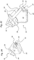
- the Fig. 1 shows in a schematic view a portion of a rotating milling drum 10 having a tool head 12 inserted on the outer circumference for abrading a bottom surface 14.
- the milling drum 10 rotating about a horizontal axis may for example be part of a tiller, forestry tiller or a stone crusher. With the aforementioned machines different types of soil can be milled.
- These tool heads 12, of which only one in the Fig. 1 is indicated schematically, are used in greater numbers on the outer circumferential surface of the milling drum 10 and fixed, usually in a uniform distribution over the working width of the milling drum 10 and / or on the outer circumference.
- the tool heads 12 are each formed by milling bits 16 and by Flachfräsm facilitatorel 16, which are respectively provided at their engagement surfaces with carbide wear surfaces, as described with reference to the FIGS. 2A to 3C are explained in more detail.
- the in the FIGS. 2A to 2C Milling bit 16 or flat milling bit 16 shown has a hard metal wear surface 18 and can be mounted in a holder 20 on the milling drum 10.
- bits 16 are often designed as pointed bits (not shown), while the bit 16 according to the invention is designed as a much more effective and wear-resistant flat milling tool 16.
- the chisel 16 is made of steel;
- the tip 18 made of carbide serves as wear protection.
- conventional pointed bits it is useful to provide uniform wear of the tip's hard metal, which is why such a bit normally rotates about its own axis in its holder and should not be fixed in position.
- these variants are disadvantageous when milling particularly abrasive floors, since the wear and thus the cost is relatively high.
- the milling tool 16 according to the invention Fig. 2A . Fig. 2B and Fig. 2C is designed so that it is provided over a larger area with carbide than flat milling chisel 16 is formed and can be inserted into the same holder 20 and in the same holding receptacle 20, as it is also used for conventional pointed chisel.
- the contact surface of the bit 16 which comes into contact with the bottom 14 ( Fig. 1 ), provided with a larger hard metal stocking 18 (cf., for example Fig. 2A ).
- a bit 16 in this embodiment must be fixed in a position so that it does not rotate in the holder or holding receptacle 20 during its use.
- equipped on its front side with the carbide insert 18 tool head 12 of the flat milling chisel 16 according to the invention is designed so that this slides over the outer contour 22 of the existing holder 20 and is secured by this positive connection against rotation.
- the tool head 12 has a collar-like widening 24 in the direction of its cylindrical drill shank 26, wherein on this collar-like widening 24 on two opposite sides each strip-like elongated flanks 28 are arranged, which slide over opposite flat sides of the outer contour 22 of the holder 20 and thereby with this outer contour 22 produce a form fit, which secures the bit 16 against rotation.
- each flat-cutting chisel 16 is provided at the end with an external thread 32, onto which a threaded nut 34 for fixing the flat-milling chisel 16 in or on the holding mount 20 can be screwed.
- the attachment of the flat milling chisel 16 takes place at the chisel shaft 26 by means of the threaded nut 34 screwed on the back, which secures the chisel shaft in the opening 30 of the holding mount 20.
- the illustrated mounting variant allows the use of a solid cutter shank 26, which is not weakened by a mounting hole, by an internal thread and / or by a circumferential groove for a snap ring attachment o.
- the back extension of the chisel shaft 26 shown in the figures, which continues into the external thread 32, provides high stability since the external thread 32 does not weaken the chisel shaft 26.
- the external thread 26 has the advantage that it can be dimensioned significantly larger than, for example, a blind-hole thread known from the prior art, which partially penetrates the tool shank (cf. DE 20 1015 101 552 U1 ).
- a typical diameter of the chisel shaft 26 of about 20 to 30 mm, there is no problem in providing an M16 or M20 external thread 32 (with outer thread diameters of 16 or 20 mm, for example).
- the fastening variant shown has the significant advantage that the external thread 32 arranged on the rear side of the drill collar 26 can be largely dimensioned independently of the diameter of the drill collar 26 as long as the external thread 32 is at least slightly smaller in diameter than the drill collar 26 itself.
- Typical dimensions for the flat milling chisel 16 shown may provide approximately its entire length from the tip 18 to the rear external thread 32 of approximately 100 to 150 mm, in particular of approximately 125 mm.
- a meaningful measure of the largest diameter of the tool head 12 on the collar-like expander 24 may be approximately at about 50 mm to about 80 mm, in particular at about 65 mm.
- the length of the tool head 12 from the rear contact surface on the holding receptacle 20 to the hard metal tip 18 may be about 35 mm to about 65 mm, in particular about 50 mm.
- all these dimensions are not to be understood as limiting and, depending on the variant embodiment of the invention, may also be chosen significantly differently.
Landscapes
- Engineering & Computer Science (AREA)
- Mining & Mineral Resources (AREA)
- Mechanical Engineering (AREA)
- Architecture (AREA)
- Civil Engineering (AREA)
- Structural Engineering (AREA)
- Drilling And Exploitation, And Mining Machines And Methods (AREA)
Applications Claiming Priority (1)
| Application Number | Priority Date | Filing Date | Title |
|---|---|---|---|
| DE102016108306.2A DE102016108306A1 (de) | 2016-05-04 | 2016-05-04 | Rotierendes Fräswerkzeug mit einer Vielzahl von auswechselbaren Werkzeugköpfen und Werkzeugkopf für ein solches rotierendes Fräswerkzeug |
Publications (1)
| Publication Number | Publication Date |
|---|---|
| EP3241948A1 true EP3241948A1 (fr) | 2017-11-08 |
Family
ID=58668741
Family Applications (1)
| Application Number | Title | Priority Date | Filing Date |
|---|---|---|---|
| EP17168568.8A Withdrawn EP3241948A1 (fr) | 2016-05-04 | 2017-04-27 | Outil de fraisage rotatif comprenant une pluralité de têtes d'outil amovibles et tête d'outil pour un tel outil de fraisage rotatif |
Country Status (2)
| Country | Link |
|---|---|
| EP (1) | EP3241948A1 (fr) |
| DE (1) | DE102016108306A1 (fr) |
Families Citing this family (1)
| Publication number | Priority date | Publication date | Assignee | Title |
|---|---|---|---|---|
| CN113215945A (zh) * | 2021-05-31 | 2021-08-06 | 济南新宇硬质合金有限公司 | 一种硬质合金公路铣刨齿 |
Citations (7)
| Publication number | Priority date | Publication date | Assignee | Title |
|---|---|---|---|---|
| DE3712135A1 (de) * | 1986-04-16 | 1987-10-22 | Taisei Road Construction | Erneuerungsmaschine fuer strassenoberflaechen |
| US5992405A (en) * | 1998-01-02 | 1999-11-30 | The Sollami Company | Tool mounting for a cutting tool |
| DE10234661A1 (de) | 2002-07-11 | 2004-01-29 | Schwamborn Entwicklungsges. Mbh | Einrichtung zur Trommelmitnahme für Bodenfräsen |
| WO2008077963A1 (fr) | 2006-12-22 | 2008-07-03 | Wirtgen Gmbh | Fraiseuse routière et procédé permettant d'obtenir le parallélisme du bâti de machine par rapport au sol |
| DE102013208539A1 (de) | 2013-05-08 | 2014-11-13 | Wirtgen Gmbh | Straßenfräsmaschine zum Bearbeiten von Straßen- oder Bodenoberflächen |
| DE202015101552U1 (de) | 2015-03-26 | 2015-05-07 | Stehr Baumaschinen Gmbh | Rotierendes Fräswerkzeug mit einer Vielzahl von auswechselbaren Werkzeugköpfen und Werkzeugkopf für ein solches rotierendes Fräswerkzeug |
| DE102014106484A1 (de) * | 2014-05-08 | 2015-11-12 | Betek Gmbh & Co. Kg | Schaftmeißel bzw. Befestigungsanordnung für einen Schaftmeißel |
-
2016
- 2016-05-04 DE DE102016108306.2A patent/DE102016108306A1/de not_active Withdrawn
-
2017
- 2017-04-27 EP EP17168568.8A patent/EP3241948A1/fr not_active Withdrawn
Patent Citations (7)
| Publication number | Priority date | Publication date | Assignee | Title |
|---|---|---|---|---|
| DE3712135A1 (de) * | 1986-04-16 | 1987-10-22 | Taisei Road Construction | Erneuerungsmaschine fuer strassenoberflaechen |
| US5992405A (en) * | 1998-01-02 | 1999-11-30 | The Sollami Company | Tool mounting for a cutting tool |
| DE10234661A1 (de) | 2002-07-11 | 2004-01-29 | Schwamborn Entwicklungsges. Mbh | Einrichtung zur Trommelmitnahme für Bodenfräsen |
| WO2008077963A1 (fr) | 2006-12-22 | 2008-07-03 | Wirtgen Gmbh | Fraiseuse routière et procédé permettant d'obtenir le parallélisme du bâti de machine par rapport au sol |
| DE102013208539A1 (de) | 2013-05-08 | 2014-11-13 | Wirtgen Gmbh | Straßenfräsmaschine zum Bearbeiten von Straßen- oder Bodenoberflächen |
| DE102014106484A1 (de) * | 2014-05-08 | 2015-11-12 | Betek Gmbh & Co. Kg | Schaftmeißel bzw. Befestigungsanordnung für einen Schaftmeißel |
| DE202015101552U1 (de) | 2015-03-26 | 2015-05-07 | Stehr Baumaschinen Gmbh | Rotierendes Fräswerkzeug mit einer Vielzahl von auswechselbaren Werkzeugköpfen und Werkzeugkopf für ein solches rotierendes Fräswerkzeug |
Also Published As
| Publication number | Publication date |
|---|---|
| DE102016108306A1 (de) | 2017-11-09 |
Similar Documents
| Publication | Publication Date | Title |
|---|---|---|
| DE102016102069A1 (de) | Werkzeughalter- und Sockelmontagebaugruppe | |
| EP3215330B1 (fr) | Outillage d'une fraiseuse de sol et fraiseuse de sol équipée d'un tel outillage | |
| DE19839440C2 (de) | Meißelhalter für ein Schrämwerkzeug | |
| EP1841949B1 (fr) | Dispositif de fraisage de pierres et d'autres materiaux et procede de fraisage de pierres et similaires faisant intervenir ledit dispositif | |
| DE60202138T2 (de) | Stumpfschleifscheibe und schneidanordnungen dafür | |
| DE60207371T2 (de) | Stumpfvermahlungsgerät | |
| DE112010001564T5 (de) | Halteanordnung für eine Schneidspitze | |
| DE112009001889T5 (de) | Bithalterblock mit sich nicht drehender Verschleisshülse | |
| DE19928034A1 (de) | Zerkleinerungs- und/oder Siebvorrichtung | |
| EP2465627B1 (fr) | Outil de forage | |
| EP2188493B1 (fr) | Trépan à molettes | |
| DE10300756A1 (de) | Stumpfzerkleinerungsmeissel | |
| DE102015115548B4 (de) | Stabmesserkopf | |
| DE102022105254A1 (de) | Scheibenlose schneidwerkzeuganordnung | |
| DE102010036650A1 (de) | Leitschaufel für eine Zerspannungsvorrichtung | |
| DE102011051584A1 (de) | Verfahren zur Lagerung eines Meißels sowie zugehörige Vorrichtung | |
| DE102017212938A1 (de) | Brechwalze mit einem Brechwerkzeug | |
| EP3241948A1 (fr) | Outil de fraisage rotatif comprenant une pluralité de têtes d'outil amovibles et tête d'outil pour un tel outil de fraisage rotatif | |
| DE102005019426B4 (de) | Werkzeug zur Erzeugung oder Nachbereitung eines Gewindes, insbesondere eines Innengewindes | |
| DE2716177C2 (de) | Einrichtung zur Sicherung eines Drehschaftmeißels gegen axiale Verschiebung | |
| DE19717498A1 (de) | Setzgerät für Ankerstangen von Verbundankern | |
| DE10161009C2 (de) | Schrämwerkzeug mit Verschleißschutzhülse | |
| DE2134781C3 (de) | Setzwerkzeug zum Eintreiben einer Gewindestange | |
| DE3125480A1 (de) | Bohrvorrichtung, insbesondere fuer das herstellen radialer abzweigbohrungen an roehren aus stahl, gusseisen, keramik etc. | |
| DE19630653C1 (de) | Verschleißarme Abstürzung eines drehbar in einem Meißelhalter gelagerten Meißels |
Legal Events
| Date | Code | Title | Description |
|---|---|---|---|
| PUAI | Public reference made under article 153(3) epc to a published international application that has entered the european phase |
Free format text: ORIGINAL CODE: 0009012 |
|
| AK | Designated contracting states |
Kind code of ref document: A1 Designated state(s): AL AT BE BG CH CY CZ DE DK EE ES FI FR GB GR HR HU IE IS IT LI LT LU LV MC MK MT NL NO PL PT RO RS SE SI SK SM TR |
|
| AX | Request for extension of the european patent |
Extension state: BA ME |
|
| 17P | Request for examination filed |
Effective date: 20180226 |
|
| RBV | Designated contracting states (corrected) |
Designated state(s): AL AT BE BG CH CY CZ DE DK EE ES FI FR GB GR HR HU IE IS IT LI LT LU LV MC MK MT NL NO PL PT RO RS SE SI SK SM TR |
|
| 17Q | First examination report despatched |
Effective date: 20180628 |
|
| STAA | Information on the status of an ep patent application or granted ep patent |
Free format text: STATUS: THE APPLICATION IS DEEMED TO BE WITHDRAWN |
|
| 18D | Application deemed to be withdrawn |
Effective date: 20190525 |