EP3237786B1 - Dichteinsatz für einen wasserablauf - Google Patents
Dichteinsatz für einen wasserablauf Download PDFInfo
- Publication number
- EP3237786B1 EP3237786B1 EP15808348.5A EP15808348A EP3237786B1 EP 3237786 B1 EP3237786 B1 EP 3237786B1 EP 15808348 A EP15808348 A EP 15808348A EP 3237786 B1 EP3237786 B1 EP 3237786B1
- Authority
- EP
- European Patent Office
- Prior art keywords
- sealing
- insert
- annular body
- sealing insert
- lips
- Prior art date
- Legal status (The legal status is an assumption and is not a legal conclusion. Google has not performed a legal analysis and makes no representation as to the accuracy of the status listed.)
- Active
Links
Images


Classifications
-
- F—MECHANICAL ENGINEERING; LIGHTING; HEATING; WEAPONS; BLASTING
- F16—ENGINEERING ELEMENTS AND UNITS; GENERAL MEASURES FOR PRODUCING AND MAINTAINING EFFECTIVE FUNCTIONING OF MACHINES OR INSTALLATIONS; THERMAL INSULATION IN GENERAL
- F16L—PIPES; JOINTS OR FITTINGS FOR PIPES; SUPPORTS FOR PIPES, CABLES OR PROTECTIVE TUBING; MEANS FOR THERMAL INSULATION IN GENERAL
- F16L17/00—Joints with packing adapted to sealing by fluid pressure
- F16L17/02—Joints with packing adapted to sealing by fluid pressure with sealing rings arranged between outer surface of pipe and inner surface of sleeve or socket
- F16L17/025—Joints with packing adapted to sealing by fluid pressure with sealing rings arranged between outer surface of pipe and inner surface of sleeve or socket the sealing rings having radially directed ribs
-
- E—FIXED CONSTRUCTIONS
- E03—WATER SUPPLY; SEWERAGE
- E03F—SEWERS; CESSPOOLS
- E03F5/00—Sewerage structures
- E03F5/04—Gullies inlets, road sinks, floor drains with or without odour seals or sediment traps
- E03F5/0407—Floor drains for indoor use
- E03F5/0408—Floor drains for indoor use specially adapted for showers
-
- E—FIXED CONSTRUCTIONS
- E03—WATER SUPPLY; SEWERAGE
- E03F—SEWERS; CESSPOOLS
- E03F5/00—Sewerage structures
- E03F5/04—Gullies inlets, road sinks, floor drains with or without odour seals or sediment traps
- E03F5/041—Accessories therefor
Definitions
- the invention relates to a sealing insert for a water drain according to claim 1.
- Such sealing inserts are used, for example, to seal a drain pan inserted into a shower base element.
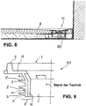
- a sealing insert 101 according to the prior art is formed by a ring body 1, which comprises a side wall 9 and a collar 13 with an upwardly projecting, in its cross-section approximately trapezoidal sealing ring 6, the smaller trapezoidal base of which points upwards.
- the outer jacket surface M of the side wall 9 is cylindrical.
- the side wall 9 consists of an outer, elastomeric wall layer 11 with three sealing lips 3, 3 ', 3 ′′ lying one above the other, as well as an inner, more rigid wall layer 12.
- the two wall layers 11, 12 can be firmly, inseparably connected to one another, or the wall layer 11 is subsequently pushed onto the wall layer 12.
- the known sealing insert has proven itself in practice, but there is a need to improve the sealing properties.
- the sealing insert 101 is characterized by relatively narrow sealing lips of the same cross-section and then tighten with screw elements.
- a sealing insert for a water drain which comprises a pipe socket and sealing lips arranged thereon.
- the sealing lips have a slightly conical contour and do not have any special contour that increases stability.
- the object is therefore to design an improved, new type of sealing insert of the type mentioned at the outset, the sealing lips of which are more stable and deform in a controlled manner when installed in the water drain and on the other hand have a high restoring force in their starting position, so that the outer areas the sealing lips exert permanently high pressure on the connection point to be sealed.
- the cone jacket sections taper in the direction of the collar, so that the side wall assumes its greatest thickness at a base of the lower sealing lips.
- the outer diameter of the sealing lips is larger than the diameter of an opening into which the sealing insert is inserted. Since the collar of the sealing insert projects beyond the sealing lips, the sealing insert can only be inserted into the opening in one direction, namely with the sealing lips first. Here, the sealing lips are deformed in their outer area against the direction of insertion.
- the conical jacket sections adjoining the sealing lips support the sealing lips. When the sealing insert is pulled out, the sealing lips are deformed in the opposite direction. As a result, the resistance and the restoring force when inserting and when the sealing insert is inserted is relatively high and when removing, for example for repair work, is relatively low.
- a cross-section of the side wall has proven to be particularly advantageous in which at least one conical surface section, hereinafter referred to as "slope", merges into a bead-like thickening, which in turn adjoins the base of the sealing lip from below.
- slope conical surface section
- the presence of the thickening can cause the sealing lip lying below the thickening to buckle when the sealing insert is inserted prevent effectively. In this way, the elastic sealing lip that was first deformed can find its original shape again as a result of the restoring force.
- the sealing lips can describe a cylindrical or conical surface, i. H. they can lie in a common or constantly decreasing or increasing radius, starting from a longitudinal axis of the ring body. Depending on the intended use, it can thus be provided that all sealing lips have an outer diameter of the same size. However, it can also be provided that the diameter is larger or smaller from sealing lip to sealing lip, so that sealing lips together form a type of cone.
- the width of the sealing lips preferably corresponds approximately to the distance between two apices lying one above the other.
- the outer, elastomeric wall layer can be made from thermoplastics which, for example, are injection molded onto the harder inner wall layer in a known manner, or are subsequently pushed on as a prefabricated molded part.
- the inner wall layer can also consist of thermoplastics, the degree of hardness of which is adjusted accordingly.
- the inner wall layer can also consist of a thermoset or metal.
- the side wall having the sealing lips in one piece with the collar and the upper sealing ring.
- the sealing lips provided for the sealing contact can be at least partially elastically deformable.
- the degree of hardness of the rest of the material of the ring body can be adjusted so that the stability of the sealing insert is guaranteed.
- the sealing inserts have a contour that is adapted to the drainage pot.
- this contour can be circular or oval.
- a sealing insert 100 is shown in its oval embodiment, comprising the ring body 1 with side wall 9 and the circumferential upper collar 13 with upwardly protruding sealing ring 6.
- the side wall 13 forms a central through opening 2.
- the side wall 13 consists of two wall layers 11, 12 joined or pushed one on top of the other, of which one, outer wall layer 11 is elastomeric and includes three sealing lips 3, 3 ', 3 "lying one above the other.
- the other, inner wall layer 12 consists of a stable, relatively hard material.
- screw receiving elements 14 which are known per se and are cranked inward are arranged.
- the Fig. 5 shows an optimized geometry (outline) of the side wall 9 in a longitudinal axial section Q through the ring body 1.
- the sealing insert 100 has three sealing lips 3, 3 ', 3 ".
- the sealing lips 3, 3', 3" each have a conical, in an apex 8 tapering contour K, which merges into a specially shaped outer jacket surface M of the side wall 9, namely into two upwardly tapering cone jacket sections 7, 7 ′′ (bevel)
- Fig. 5 shows, the sealing lips 3, 3 ', 3 "are thicker compared to the sealing lips according to the prior art (cf. Fig. 9 ) executed. It is advantageous that the bevels 7, 7 ′′ each merge via a concave rounding 16 into a wider base 15 of the sealing lip 3, 3 ′, 3 ′′.
- the Figures 6 and 7 show a particularly advantageous embodiment in which the lower bevel 7 is followed by a bead-like thickening 5, which in turn merges from below to the base 15 of the central sealing lip 3 '.
- the sealing lip 3 has a height H which is greater than a spacing B provided between the sealing lip 3 and the thickening 5.
- the deformation of the lowermost sealing lip 3 is substantially limited and bending of the sealing lip is limited.
- the sealing lip 3 cannot lean completely against the wall 11; rather, the apex area of the sealing lip 3 is supported by the bead-like thickening 5.
- a bead-like thickening 5 is only provided below the second sealing lip 3 'in the exemplary embodiment. Not excluded is, however, that the sealing lips 3 'and / or 3 "are also supported by further bead-like thickenings.
- the apices 8 of the sealing lips 3, 3 ', 3 "lying one above the other lie along a line designated by 18, which is arranged in a common radius R, measured from a longitudinal axis X of the ring body 1, that is, parallel to the longitudinal axis X.
- the Fig. 7 but also shows a different embodiment in which the vertices 8 (denoted by a dashed line) are arranged along a slightly inclined line 19. Accordingly, the vertices 8 describe radii R, R ′, R ′′ that decrease in the upward direction, starting from said longitudinal axis X of the ring body 1.
- the sealing lips 3, 3 ', 3 ′′ can have graduated degrees of hardness or softness.
- the upper sealing lip can be made somewhat harder than the lower one.
- FIGS. 3 and 4 show the sealing insert 100 in its circular, rotationally symmetrical design.
- the reference numbers of the circular sealing insert correspond to the parts of the oval sealing insert already described.
- the Fig. 8 shows the sealing insert 100 according to the invention, installed in a horizontal water drain 10 of a barrier-free shower.
- Reference number 4 denotes a plate-shaped shower base element.
Description
- Die Erfindung betrifft einen Dichteinsatz für einen Wasserablauf gemäß Anspruch 1.
- Solche Dichteinsätze werden beispielsweise eingesetzt um einen in ein Duschbodenelement eingesetzten Ablauftopf abzudichten.
- Ein Dichteinsatz 101 gemäß dem Stand der Technik (vgl.
Fig. 9 ) ist durch einen Ringkorpus 1 gebildet, welcher eine Seitenwand 9 und einen Kragen 13 mit einem nach oben ragenden, in seinem Querschnitt etwa trapezförmigen Dichtring 6 umfasst, dessen kleinere Trapezbasis nach oben zeigt. Die Außenmantelfläche M der Seitenwand 9 ist zylindrisch. - Die Begriffe: "oben", "obere", "unten", "untere" bzw. "unterhalb" beziehen sich auf die Anordnung des Dichteinsatzes 101 in seiner Einbaulage, bei der der Kragen 13 mit dem Dichtring 6 dem Duschbodenelement zugewandt ist.
- Die Seitenwand 9 besteht aus einer äußeren, elastomeren Wandungsschicht 11 mit drei übereinander liegenden Dichtlippen 3, 3', 3" sowie aus einer inneren, steiferen Wandungsschicht 12. Die beiden Wandungsschichten 11, 12 können miteinander fest, untrennbar verbunden sein, oder die Wandungsschicht 11 ist auf die Wandungsschicht 12 nachträglich aufgeschoben. Der bekannte Dichteinsatz hat sich in der Praxis gut bewährt, jedoch besteht Bedarf an einer Verbesserung der Dichteigenschaften. Der Dichteinsatz 101 zeichnet sich durch relativ schmale Dichtlippen von demselben Querschnitt aus. Die Dichtlippen können bei der Montage des Ringkorpus und anschließendem Anziehen mit Schraubelementen umknicken.
- Aus
DE 20 2010 007 534 U1 und ausDE 20 2009 015 791 U1 ist jeweils ein Dichteinsatz für einen Wasserablauf bekannt, der einen Rohrstutzen sowie daran angeordnete Dichtlippen umfasst. Die Dichtlippen haben eine leicht konische Kontur und weisen keine besondere, die Stabilität erhöhende Kontur auf. - Es stellt sich daher die Aufgabe, einen verbesserten, neuartigen Dichteinsatz der eingangs genannten Art zu konzipieren, dessen Dichtlippen stabiler sind und sich beim Einmontieren in den Wasserablauf zum einen kontrolliert deformieren und zum anderen eine hohe Rückstellkraft in ihre Ausgangsposition aufweisen, so dass die äußeren Bereiche der Dichtlippen einen dauerhaft hohen Druck auf die abzudichtende Verbindungsstelle ausüben.
- Diese Aufgabe ist durch einen gattungsgemäßen Dichteinsatz mit den Merkmalen des Anspruchs 1 gelöst.
- Die Kegelmantel-Abschnitte verjüngen sich in Richtung Kragen, so dass die Seitenwand ihre größte Dicke bei einer Basis der unteren Dichtlippen annimmt. Der äußere Durchmesser der Dichtlippen ist aus funktionalen Gründen größer als der Durchmesser einer Öffnung, in welche der Dichteinsatz eingesetzt wird. Da der Kragen des Dichteinsatzes die Dichtlippen überragt, kann der Dichteinsatz nur in einer Richtung, nämlich mit den Dichtlippen zuerst, in die Öffnung eingesetzt werden. Hierbei werden die Dichtlippen in ihrem Außenbereich entgegen der Einsetzrichtung verformt. Die sich an die Dichtlippen anschließenden Kegelmantel-Abschnitte stützen hierbei die Dichtlippen ab. Beim Herausziehen des Dichteinsatzes werden die Dichtlippen in die entgegengesetzte Richtung verformt. Im Ergebnis ist hierdurch der Widerstand und die Rückstellkraft beim Einsetzen und bei eingesetztem Dichteinsatz relativ hoch und beim Ausbau, beispielsweise für Reparaturarbeiten, relativ niedrig.
- Als besonders vorteilhaft hat sich ein Querschnitt der Seitenwand erwiesen, bei dem wenigstens ein Kegelmantel-Abschnitt, im Weiteren als "Schräge" bezeichnet, in eine wulstartige Verdickung übergeht, welche sich wiederum von unten an die Basis der Dichtlippe anschließt. Das Vorhandensein der Verdickung kann ein Umknicken der unterhalb der Verdickung liegenden Dichtlippe beim Einsetzen des Dichteinsatzes wirksam verhindern. So kann die zuerst verformte, elastische Dichtlippe infolge der Rückstellkraft wieder ihre ursprüngliche Form zurück finden.
- Die Dichtlippen können mit ihren Scheiteln bzw. Außenkanten eine zylindrische oder konische Fläche beschreiben, d. h. sie können in einem gemeinsamen oder sich stets verkleinernden bzw. vergrößernden Radius, ausgehend von einer Längsachse des Ringkorpus, liegen. In Abhängigkeit vom Einsatzzweck kann somit vorgesehen sein, dass alle Dichtlippen einen gleich großen äußeren Durchmesser aufweisen. Es kann aber auch vorgesehen sein, dass der Durchmesser von Dichtlippe zu Dichtlippe größer oder kleiner wird, so dass Dichtlippen gemeinsam eine Art Konus ausbilden.
- Vorzugsweise entspricht die Breite der Dichtlippen, gemessen zwischen der Basis der Dichtlippe und ihrem Scheitel etwa dem Abstand zwischen zwei übereinander liegenden Scheiteln.
- Die äußere, elastomere Wandungsschicht kann aus Thermoplasten hergestellt sein, welche beispielsweise auf die härtere innere Wandungsschicht auf bekannte Weise angespritzt sind, oder als vorgefertigtes Formteil nachträglich aufgeschoben wird. Die innere Wandungsschicht kann ebenso aus Thermoplasten bestehen, deren Härtegrad entsprechend eingestellt ist. Die innere Wandungsschicht kann auch aus einem Duroplast oder Metall bestehen.
- Schließlich ist es möglich, die die Dichtlippen aufweisende Seitenwand einstückig mit dem Kragen und dem oberen Dichtring anzufertigen. Dabei können die für den Dichtkontakt vorgesehenen Dichtlippen wenigstens teilweise elastisch verformbar sein. Der Härtegrad des übrigen Materials des Ringkorpus kann so eingestellt sein, dass die Stabilität des Dichteinsatzes gewährt ist.
- Die Dichteinsätze weisen eine an den Ablauftopf angepasste Kontur auf. Insbesondere kann diese Kontur kreisrund oder oval sein.
- Ausführungsbeispiele der Erfindung sind anhand der Zeichnung näher erläutert. Die Figuren zeigen:
- Fig. 1
- einen ovalen Dichteinsatz gemäß Erfindung in einer Draufsicht auf seinen Dichtring;
- Fig. 2
- einen Schnitt A-A gemäß
Fig. 1 ; - Figuren 3 und 4
- einen kreisrunden Dichteinsatz gemäß Erfindung, jeweils in einer perspektivischen Ansicht;
- Fig. 5
- einen vergrößerten längsaxialen Schnitt durch den Dichteinsatz gemäß Erfindung, in einer ersten Ausführung;
- Fig. 6
- einen vergrößerten längsaxialen Schnitt durch den Dichteinsatz gemäß Erfindung, in einer zweiten, optimierten Ausführung;
- Fig. 7
- einen vergrößerten längsaxialen Schnitt durch den Dichteinsatz, in einer massiven Ausführung;
- Fig. 8
- Einbaulage des Dichteinsatzes gemäß Erfindung, in einem schematischen Schnitt im Bodenbereich einer Duschzelle; und
- Fig. 9
- einen Dichteinsatz gemäß dem Stand der Technik, in einem Schnitt.
- Gleiche oder ähnliche Elemente können in den nachfolgenden Figuren mit gleichen oder ähnlichen Bezugszeichen versehen sein.
In denFiguren 1 und 2 ist ein Dichteinsatz 100 in seiner ovalen Ausführungsform dargestellt, umfassend den Ringkorpus 1 mit Seitenwand 9 und dem umlaufenden oberen Kragen 13 mit nach oben ragendem Dichtring 6. Die Seitenwand 13 bildet eine zentrale Durchgangsöffnung 2. - Die Seitenwand 13 besteht aus zwei zusammengefügten, bzw. übereinander geschobenen Wandungsschichten 11, 12, von denen die eine, äußere Wandungsschicht 11 elastomer ist und drei übereinander liegende Dichtlippen 3, 3', 3" mit einschließt. Die andere, innere Wandungsschicht 12 besteht aus einem stabilen, relativ harten Material.
- An einem schrägen, oberen Abschnitt 17 der Seitenwand 9 sind an sich bekannte, nach innen gekröpfte Schraubaufnahmeelemente 14 angeordnet.
- Die
Fig. 5 zeigt eine optimierte Geometrie (Umriss) der Seitenwand 9 in einem längsaxialen Schnitt Q durch den Ringkorpus 1. Der Dichteinsatz 100 weist drei Dichtlippen 3, 3', 3" auf. Die Dichtlippen 3, 3', 3" weisen jeweils eine konische, in einen Scheitel 8 auslaufende Kontur K auf, welche in eine speziell geformte Außenmantelfläche M der Seitenwand 9, nämlich in zwei sich nach oben verjüngende Kegelmantel-Abschnitte 7, 7" (Schräge) übergeht. Wie dieFig. 5 zeigt, sind die Dichtlippen 3, 3', 3" dicker gegenüber den Dichtlippen gemäß dem Stand der Technik (vergl.Fig. 9 ) ausgeführt. Vorteilhaft ist, dass die Schrägen 7, 7" jeweils über eine konkave Rundung 16 in eine breitere Basis 15 der Dichtlippe 3, 3', 3" übergehen. - Die
Figuren 6 und 7 zeigen eine insbesondere vorteilhafte Ausführung, bei der sich an die untere Schräge 7 eine wulstartige Verdickung 5 anschließt, welche wiederum von unten an die Basis 15 der mittleren Dichtlippe 3' übergeht. Die Dichtlippe 3 weist eine Höhe H auf, die größer ist als ein zwischen der Dichtlippe 3 und der Verdickung 5 vorgesehener Abstand B. Dadurch wird die Verformung der untersten Dichtlippe 3 wesentlich begrenzt und ein Umknicken der Dichtlippe begrenzt. Beim Einsetzen in eine Öffnung kann sich die Dichtlippe 3 somit nicht vollständig an die Wandung 11 anlehnen, der Scheitelbereich der Dichtlippe 3 wird vielmehr von der wulstartigen Verdickung 5 abgestützt. - Da die Umknickgefahr bei der ersten in die Öffnung eines Bodens oder einer Bodenplatte einzusetzenden Dichtlippe 3 am größten ist, ist im Ausführungsbeispiel eine wulstartige Verdickung 5 nur unterhalb der zweiten Dichtlippe 3' vorgesehen. Nicht ausgeschlossen ist jedoch, dass auch die Dichtlippen 3' und/oder 3" durch weitere wulstartige Verdickungen abgestützt werden.
- Gemäß
Figuren 6 und 7 liegen die Scheitel 8 der übereinander liegenden Dichtlippen 3, 3', 3" entlang einer mit 18 bezeichneten Linie, die in einem gemeinsamen Radius R, bemessen von einer Längsachse X des Ringkorpus 1, also parallel zur Längsachse X angeordnet ist. - Die
Fig. 7 zeigt aber auch eine abweichende Ausführung, bei der die Scheitel 8 (mit Strichlinie bezeichnet) entlang einer leicht geneigten Linie 19 angeordnet sind. Demnach beschreiben die Scheitel 8 sich nach oben verkleinernde Radien R, R', R", ausgehend von der besagten Längsachse X des Ringkorpus 1. - Die Dichtlippen 3, 3', 3" können gestufte Härte- bzw. Weichgrade aufweisen. Beispielsweise kann die obere Dichtlippe etwas härter als die untere ausgeführt sein.
- Die
Figuren 3 und 4 zeigen den Dichteinsatz 100 in seiner kreisrunden, rotationssymmetrischen Ausführung. Die Bezugszahlen des kreisrunden Dichteinsatzes entsprechen den bereits beschriebenen Teilen des ovalen Dichteinsatzes. - Die
Fig. 8 zeigt den Dichteinsatz 100 gemäß Erfindung, eingebaut in einen waagerechten Wasserablauf 10 einer barrierefreien Dusche. Mit Bezugszahl 4 ist ein plattenförmiges Duschbodenelement bezeichnet.Bezugszeichenliste: 1 Ringkorpus 2 Durchqanqsöffnunq 3, 3', 3" Dichtlippe 4 Duschbodenelement 5 Verdickung 6 Dichtring 7 Keqelmantel-Abschnitt (Schräge) 8 Scheitel 9 Seitenwand 10 Wasserablauf 11 Wandunqsschicht 12 Wandunqsschicht 13 Kragen 14 Schraubaufnahmeelement 15 Basis 16 konkave Rundung 17 Abschnitt (v. 9) 18 Linie 19 Linie 100, 101 Dichteinsatz B Abstand H Höhe M Außenmantelfläche K Kontur Q Schnitt A - A Schnitt R; R'; R" Radius X Längsachse
Claims (8)
- Dichteinsatz (100) für einen Wasserablauf (10), umfassend:- einen Ringkorpus (1) mit einer Seitenwand (9) und einem umlaufenden Kragen (13);- wenigstens eine an der Seitenwand (9) angeordnete, nach außen zeigende Dichtlippe (3, 3', 3"),- wobei die wenigstens eine Dichtlippe (3, 3', 3") in einem längsaxialen Schnitt (Q) durch den Dichteinsatz (100) eine konische, in einen Scheitel (8) auslaufende Kontur (K) aufweist, welche in eine Außenmantelfläche (M) des Ringkorpus (1) übergeht,- und wobei die Seitenwand (9) des Ringkorpus (1) einen an die wenigstens eine Dichtlippe (3, 3', 3") angrenzenden Kegelmantel-Abschnitt (7, 7') aufweist,dadurch gekennzeichnet, dass der Kegelmantel-Abschnitt (7, 7') sich in Richtung Kragen (13) verjüngt.
- Dichteinsatz (100) nach Anspruch 1, dadurch gekennzeichnet, dass an den Kegelmantel-Abschnitt (7, 7') sich wenigstens eine umlaufende, wulstartige, in die Dichtlippe (3', 3") übergehende Verdickung (5), anschließt.
- Dichteinsatz (100) nach Anspruch 2, dadurch gekennzeichnet, dass er drei übereinander angeordnete Dichtlippen aufweist, wobei die mittlere Dichtlippe die Verdickung (5) aufweist, wobei die untere Dichtlippe eine Höhe (H) aufweist, die im längsaxialen Schnitt (Q) definiert ist durch den Abstand ihres Scheitels (8) zu ihrem Schnittpunkt mit dem oben anschließenden Kegelmantelabschnitt (7, 7'), und die Höhe (H) größer ist, als ein zwischen der unteren Dichtlippe (3, 3', 3") und der Verdickung (5) der oberen Dichtlippe vorgesehener Abstand (B), so dass sich die in Richtung Verdickung (5) umknickende untere Dichtlippe (3, 3', 3") im Bereich ihres Scheitels (8) an der Verdickung (5) abstützt.
- Dichteinsatz (100) mit einem kreisförmigen Ringkorpus nach einem der Ansprüche 1 bis 3, dadurch gekennzeichnet, dass drei übereinander liegende Dichtlippen (3, 3', 3") vorgesehen sind und die Scheitel (8) übereinander liegender Dichtlippen (3, 3', 3") - im längsaxialen Schnitt (Q) durch den Dichteinsatz (100) - in einem gemeinsamen Radius (R), ausgehend von einer Längsachse (X) des Ringkorpus (1), liegen.
- Dichteinsatz (100) mit einem kreisförmigen Ringkorpus nach einem der Ansprüche 1 bis 3, dadurch gekennzeichnet, dass drei übereinander liegende Dichtlippen (3, 3', 3") vorgesehen sind und die Scheitel (8) der übereinander liegenden Dichtlippen (3, 3', 3") - im längsaxialen Schnitt (Q) durch den Dichteinsatz (100) - in unterschiedlichen Radien (R, R', R"), ausgehend von einer ängsachse (X) des Ringkorpus (1), liegen.
- Dichteinsatz (100) nach einem der Ansprüche 1 bis 5, dadurch gekennzeichnet, dass die Seitenwand (9) aus zwei miteinander fest gefügten Wandungsschichten (11; 12) besteht.
- Dichteinsatz (100) nach Anspruch 6, dadurch gekennzeichnet, dass die eine Wandungsschicht (11) aus elastomerem Material besteht und die Dichtlippen (3, 3', 3") mit einschließt, dagegen die andere Wandungsschicht (12) aus härterem Material als das der elastomeren Wandungsschicht (11) besteht.
- Dichteinsatz (100) nach einem der Ansprüche 1 bis 5, dadurch gekennzeichnet, dass der Ringkorpus (1) in einem Materialstück gefertigt ist, wobei die für den Dichtkontakt vorgesehenen Dichtlippen (3, 3', 3"), wenigstens teilweise elastisch verformbar sind, dagegen das übrige Material des Ringkorpus (1) steifer ist.
Applications Claiming Priority (2)
| Application Number | Priority Date | Filing Date | Title |
|---|---|---|---|
| DE102014119582.5A DE102014119582B4 (de) | 2014-12-23 | 2014-12-23 | Dichteinsatz für einen Wasserablauf |
| PCT/EP2015/002339 WO2016102038A1 (de) | 2014-12-23 | 2015-11-21 | Dichteinsatz für einen wasserablauf |
Publications (2)
| Publication Number | Publication Date |
|---|---|
| EP3237786A1 EP3237786A1 (de) | 2017-11-01 |
| EP3237786B1 true EP3237786B1 (de) | 2021-05-19 |
Family
ID=54849587
Family Applications (1)
| Application Number | Title | Priority Date | Filing Date |
|---|---|---|---|
| EP15808348.5A Active EP3237786B1 (de) | 2014-12-23 | 2015-11-21 | Dichteinsatz für einen wasserablauf |
Country Status (4)
| Country | Link |
|---|---|
| EP (1) | EP3237786B1 (de) |
| DE (1) | DE102014119582B4 (de) |
| DK (1) | DK3237786T3 (de) |
| WO (1) | WO2016102038A1 (de) |
Families Citing this family (3)
| Publication number | Priority date | Publication date | Assignee | Title |
|---|---|---|---|---|
| DE102016125311A1 (de) | 2016-12-22 | 2018-06-28 | Wedi Gmbh | Wasserablauf für einen Duschboden mit einem universell einsetzbaren Anschlussadapter |
| CN108488380A (zh) * | 2018-04-27 | 2018-09-04 | 北京洛科瀚科技有限公司 | 一种双硬度波纹式橡胶密封圈 |
| US10604926B2 (en) * | 2018-05-04 | 2020-03-31 | Georg Fischer Harvel Llc | Drain apparatus for marine vessel |
Family Cites Families (5)
| Publication number | Priority date | Publication date | Assignee | Title |
|---|---|---|---|---|
| FR1432209A (fr) * | 1965-04-30 | 1966-03-18 | Fribaud Et Cie Soc Ets | Pièce de raccordement pour cuvette de water-closet |
| NL1010333C2 (nl) * | 1998-10-16 | 2000-04-18 | Artech Rubber B V | Samengesteld hulsvormig afdichtingsmiddel. |
| DE202004017607U1 (de) * | 2004-11-12 | 2006-03-16 | Kessel Gmbh | Einsatzteil und Ablaufsystem |
| DE202009015791U1 (de) * | 2009-11-18 | 2010-02-18 | Dallmer Gmbh & Co. Kg | Ablaufvorrichtung |
| DE202010007534U1 (de) * | 2010-06-02 | 2010-09-02 | Wedi, Stephan | Entwässerungsablauf zum Einbau in eine Bodenöffnung eines Duschplatzes |
-
2014
- 2014-12-23 DE DE102014119582.5A patent/DE102014119582B4/de not_active Expired - Fee Related
-
2015
- 2015-11-21 DK DK15808348.5T patent/DK3237786T3/da active
- 2015-11-21 WO PCT/EP2015/002339 patent/WO2016102038A1/de active Application Filing
- 2015-11-21 EP EP15808348.5A patent/EP3237786B1/de active Active
Non-Patent Citations (1)
| Title |
|---|
| None * |
Also Published As
| Publication number | Publication date |
|---|---|
| WO2016102038A1 (de) | 2016-06-30 |
| DE102014119582B4 (de) | 2016-10-27 |
| DK3237786T3 (da) | 2021-08-02 |
| DE102014119582A1 (de) | 2016-06-23 |
| EP3237786A1 (de) | 2017-11-01 |
Similar Documents
| Publication | Publication Date | Title |
|---|---|---|
| DE60104554T2 (de) | Klammermatter | |
| DE3007702A1 (de) | Inspektionskammer fuer eine drainageanlage | |
| EP3237786B1 (de) | Dichteinsatz für einen wasserablauf | |
| DE202014003383U1 (de) | Schlauchkupplung | |
| DE102007014795B4 (de) | Halteeinrichtung sowie Halteelement hierfür | |
| DE102004025466B4 (de) | Verschlusskappe | |
| WO2013093900A1 (de) | Maul- oder klauenförmige spaltdichtung | |
| EP2902567A1 (de) | Bodenbelag aus Plattenelementen | |
| DE102014119584B3 (de) | Dichteinsatz für einen Wasserablauf | |
| DE1400801A1 (de) | Kontermutter und Verfahren zu ihrer Herstellung | |
| DE2238438A1 (de) | Reifenventilkern | |
| DE102014005837B3 (de) | Schlauchkupplung | |
| EP2282098A2 (de) | Dichtung mit verschiebbarem Dichtungsteil | |
| DE202015105945U1 (de) | Schutzring für Gasflaschen | |
| DE2900812B1 (de) | Schutzkappe fuer Ablaufventile von Waschbecken,Wannen u.dgl. | |
| DE2648627B2 (de) | Mehrteiliger Siphon für sanitäre Anlagen | |
| EP3597834A1 (de) | Bauteil für eine ablaufvorrichtung für ein flachdach mit attika | |
| EP3485101B1 (de) | Ablaufsieb für ein waschbecken | |
| EP2636805B1 (de) | Waschbecken mit einer Ablauföffnung | |
| DE10043280B4 (de) | Vorrichtung zur Abdichtung | |
| DE19949697B4 (de) | Vorrichtung zum Verschliessen von Rohrenden | |
| DE102016103275A1 (de) | Dichtung einer Entwässerungsrinne | |
| DE20320542U1 (de) | Dichtring für Steckmuffenverbindungen | |
| DE202004002031U1 (de) | Dichtring für Steckmuffenverbindungen | |
| DE202021106732U1 (de) | Hygiene-Verschluss für Standrohre sowie Anordnung aus Standrohr und Hygiene-Verschluss |
Legal Events
| Date | Code | Title | Description |
|---|---|---|---|
| STAA | Information on the status of an ep patent application or granted ep patent |
Free format text: STATUS: THE INTERNATIONAL PUBLICATION HAS BEEN MADE |
|
| PUAI | Public reference made under article 153(3) epc to a published international application that has entered the european phase |
Free format text: ORIGINAL CODE: 0009012 |
|
| STAA | Information on the status of an ep patent application or granted ep patent |
Free format text: STATUS: REQUEST FOR EXAMINATION WAS MADE |
|
| 17P | Request for examination filed |
Effective date: 20170615 |
|
| AK | Designated contracting states |
Kind code of ref document: A1 Designated state(s): AL AT BE BG CH CY CZ DE DK EE ES FI FR GB GR HR HU IE IS IT LI LT LU LV MC MK MT NL NO PL PT RO RS SE SI SK SM TR |
|
| AX | Request for extension of the european patent |
Extension state: BA ME |
|
| DAV | Request for validation of the european patent (deleted) | ||
| DAX | Request for extension of the european patent (deleted) | ||
| REG | Reference to a national code |
Ref country code: DE Ref legal event code: R079 Ref document number: 502015014738 Country of ref document: DE Free format text: PREVIOUS MAIN CLASS: F16L0017025000 Ipc: E03F0005040000 |
|
| STAA | Information on the status of an ep patent application or granted ep patent |
Free format text: STATUS: EXAMINATION IS IN PROGRESS |
|
| RIC1 | Information provided on ipc code assigned before grant |
Ipc: E03F 5/04 20060101AFI20190708BHEP |
|
| 17Q | First examination report despatched |
Effective date: 20190730 |
|
| GRAP | Despatch of communication of intention to grant a patent |
Free format text: ORIGINAL CODE: EPIDOSNIGR1 |
|
| STAA | Information on the status of an ep patent application or granted ep patent |
Free format text: STATUS: GRANT OF PATENT IS INTENDED |
|
| INTG | Intention to grant announced |
Effective date: 20201207 |
|
| GRAS | Grant fee paid |
Free format text: ORIGINAL CODE: EPIDOSNIGR3 |
|
| GRAA | (expected) grant |
Free format text: ORIGINAL CODE: 0009210 |
|
| STAA | Information on the status of an ep patent application or granted ep patent |
Free format text: STATUS: THE PATENT HAS BEEN GRANTED |
|
| AK | Designated contracting states |
Kind code of ref document: B1 Designated state(s): AL AT BE BG CH CY CZ DE DK EE ES FI FR GB GR HR HU IE IS IT LI LT LU LV MC MK MT NL NO PL PT RO RS SE SI SK SM TR |
|
| REG | Reference to a national code |
Ref country code: GB Ref legal event code: FG4D Free format text: NOT ENGLISH |
|
| REG | Reference to a national code |
Ref country code: CH Ref legal event code: EP |
|
| REG | Reference to a national code |
Ref country code: DE Ref legal event code: R096 Ref document number: 502015014738 Country of ref document: DE |
|
| REG | Reference to a national code |
Ref country code: AT Ref legal event code: REF Ref document number: 1394084 Country of ref document: AT Kind code of ref document: T Effective date: 20210615 |
|
| REG | Reference to a national code |
Ref country code: IE Ref legal event code: FG4D Free format text: LANGUAGE OF EP DOCUMENT: GERMAN |
|
| REG | Reference to a national code |
Ref country code: DK Ref legal event code: T3 Effective date: 20210727 |
|
| REG | Reference to a national code |
Ref country code: NL Ref legal event code: FP |
|
| REG | Reference to a national code |
Ref country code: LT Ref legal event code: MG9D |
|
| PG25 | Lapsed in a contracting state [announced via postgrant information from national office to epo] |
Ref country code: HR Free format text: LAPSE BECAUSE OF FAILURE TO SUBMIT A TRANSLATION OF THE DESCRIPTION OR TO PAY THE FEE WITHIN THE PRESCRIBED TIME-LIMIT Effective date: 20210519 Ref country code: BG Free format text: LAPSE BECAUSE OF FAILURE TO SUBMIT A TRANSLATION OF THE DESCRIPTION OR TO PAY THE FEE WITHIN THE PRESCRIBED TIME-LIMIT Effective date: 20210819 Ref country code: LT Free format text: LAPSE BECAUSE OF FAILURE TO SUBMIT A TRANSLATION OF THE DESCRIPTION OR TO PAY THE FEE WITHIN THE PRESCRIBED TIME-LIMIT Effective date: 20210519 Ref country code: FI Free format text: LAPSE BECAUSE OF FAILURE TO SUBMIT A TRANSLATION OF THE DESCRIPTION OR TO PAY THE FEE WITHIN THE PRESCRIBED TIME-LIMIT Effective date: 20210519 |
|
| PG25 | Lapsed in a contracting state [announced via postgrant information from national office to epo] |
Ref country code: GR Free format text: LAPSE BECAUSE OF FAILURE TO SUBMIT A TRANSLATION OF THE DESCRIPTION OR TO PAY THE FEE WITHIN THE PRESCRIBED TIME-LIMIT Effective date: 20210820 Ref country code: LV Free format text: LAPSE BECAUSE OF FAILURE TO SUBMIT A TRANSLATION OF THE DESCRIPTION OR TO PAY THE FEE WITHIN THE PRESCRIBED TIME-LIMIT Effective date: 20210519 Ref country code: IS Free format text: LAPSE BECAUSE OF FAILURE TO SUBMIT A TRANSLATION OF THE DESCRIPTION OR TO PAY THE FEE WITHIN THE PRESCRIBED TIME-LIMIT Effective date: 20210919 Ref country code: PT Free format text: LAPSE BECAUSE OF FAILURE TO SUBMIT A TRANSLATION OF THE DESCRIPTION OR TO PAY THE FEE WITHIN THE PRESCRIBED TIME-LIMIT Effective date: 20210920 Ref country code: NO Free format text: LAPSE BECAUSE OF FAILURE TO SUBMIT A TRANSLATION OF THE DESCRIPTION OR TO PAY THE FEE WITHIN THE PRESCRIBED TIME-LIMIT Effective date: 20210819 Ref country code: PL Free format text: LAPSE BECAUSE OF FAILURE TO SUBMIT A TRANSLATION OF THE DESCRIPTION OR TO PAY THE FEE WITHIN THE PRESCRIBED TIME-LIMIT Effective date: 20210519 Ref country code: SE Free format text: LAPSE BECAUSE OF FAILURE TO SUBMIT A TRANSLATION OF THE DESCRIPTION OR TO PAY THE FEE WITHIN THE PRESCRIBED TIME-LIMIT Effective date: 20210519 Ref country code: RS Free format text: LAPSE BECAUSE OF FAILURE TO SUBMIT A TRANSLATION OF THE DESCRIPTION OR TO PAY THE FEE WITHIN THE PRESCRIBED TIME-LIMIT Effective date: 20210519 |
|
| PG25 | Lapsed in a contracting state [announced via postgrant information from national office to epo] |
Ref country code: RO Free format text: LAPSE BECAUSE OF FAILURE TO SUBMIT A TRANSLATION OF THE DESCRIPTION OR TO PAY THE FEE WITHIN THE PRESCRIBED TIME-LIMIT Effective date: 20210519 Ref country code: ES Free format text: LAPSE BECAUSE OF FAILURE TO SUBMIT A TRANSLATION OF THE DESCRIPTION OR TO PAY THE FEE WITHIN THE PRESCRIBED TIME-LIMIT Effective date: 20210519 Ref country code: SM Free format text: LAPSE BECAUSE OF FAILURE TO SUBMIT A TRANSLATION OF THE DESCRIPTION OR TO PAY THE FEE WITHIN THE PRESCRIBED TIME-LIMIT Effective date: 20210519 Ref country code: SK Free format text: LAPSE BECAUSE OF FAILURE TO SUBMIT A TRANSLATION OF THE DESCRIPTION OR TO PAY THE FEE WITHIN THE PRESCRIBED TIME-LIMIT Effective date: 20210519 Ref country code: CZ Free format text: LAPSE BECAUSE OF FAILURE TO SUBMIT A TRANSLATION OF THE DESCRIPTION OR TO PAY THE FEE WITHIN THE PRESCRIBED TIME-LIMIT Effective date: 20210519 Ref country code: EE Free format text: LAPSE BECAUSE OF FAILURE TO SUBMIT A TRANSLATION OF THE DESCRIPTION OR TO PAY THE FEE WITHIN THE PRESCRIBED TIME-LIMIT Effective date: 20210519 |
|
| REG | Reference to a national code |
Ref country code: DE Ref legal event code: R097 Ref document number: 502015014738 Country of ref document: DE |
|
| PLBE | No opposition filed within time limit |
Free format text: ORIGINAL CODE: 0009261 |
|
| STAA | Information on the status of an ep patent application or granted ep patent |
Free format text: STATUS: NO OPPOSITION FILED WITHIN TIME LIMIT |
|
| 26N | No opposition filed |
Effective date: 20220222 |
|
| PG25 | Lapsed in a contracting state [announced via postgrant information from national office to epo] |
Ref country code: IS Free format text: LAPSE BECAUSE OF FAILURE TO SUBMIT A TRANSLATION OF THE DESCRIPTION OR TO PAY THE FEE WITHIN THE PRESCRIBED TIME-LIMIT Effective date: 20210919 Ref country code: AL Free format text: LAPSE BECAUSE OF FAILURE TO SUBMIT A TRANSLATION OF THE DESCRIPTION OR TO PAY THE FEE WITHIN THE PRESCRIBED TIME-LIMIT Effective date: 20210519 |
|
| REG | Reference to a national code |
Ref country code: DE Ref legal event code: R119 Ref document number: 502015014738 Country of ref document: DE |
|
| REG | Reference to a national code |
Ref country code: DK Ref legal event code: EBP Effective date: 20211130 |
|
| PG25 | Lapsed in a contracting state [announced via postgrant information from national office to epo] |
Ref country code: MC Free format text: LAPSE BECAUSE OF FAILURE TO SUBMIT A TRANSLATION OF THE DESCRIPTION OR TO PAY THE FEE WITHIN THE PRESCRIBED TIME-LIMIT Effective date: 20210519 |
|
| REG | Reference to a national code |
Ref country code: CH Ref legal event code: PL |
|
| REG | Reference to a national code |
Ref country code: NL Ref legal event code: MM Effective date: 20211201 |
|
| GBPC | Gb: european patent ceased through non-payment of renewal fee |
Effective date: 20211121 |
|
| PG25 | Lapsed in a contracting state [announced via postgrant information from national office to epo] |
Ref country code: LU Free format text: LAPSE BECAUSE OF NON-PAYMENT OF DUE FEES Effective date: 20211121 Ref country code: IT Free format text: LAPSE BECAUSE OF FAILURE TO SUBMIT A TRANSLATION OF THE DESCRIPTION OR TO PAY THE FEE WITHIN THE PRESCRIBED TIME-LIMIT Effective date: 20210519 Ref country code: BE Free format text: LAPSE BECAUSE OF NON-PAYMENT OF DUE FEES Effective date: 20211130 |
|
| REG | Reference to a national code |
Ref country code: BE Ref legal event code: MM Effective date: 20211130 |
|
| PG25 | Lapsed in a contracting state [announced via postgrant information from national office to epo] |
Ref country code: LI Free format text: LAPSE BECAUSE OF NON-PAYMENT OF DUE FEES Effective date: 20211130 Ref country code: CH Free format text: LAPSE BECAUSE OF NON-PAYMENT OF DUE FEES Effective date: 20211130 |
|
| PG25 | Lapsed in a contracting state [announced via postgrant information from national office to epo] |
Ref country code: NL Free format text: LAPSE BECAUSE OF NON-PAYMENT OF DUE FEES Effective date: 20211201 |
|
| PG25 | Lapsed in a contracting state [announced via postgrant information from national office to epo] |
Ref country code: IE Free format text: LAPSE BECAUSE OF NON-PAYMENT OF DUE FEES Effective date: 20211121 Ref country code: GB Free format text: LAPSE BECAUSE OF NON-PAYMENT OF DUE FEES Effective date: 20211121 Ref country code: DK Free format text: LAPSE BECAUSE OF NON-PAYMENT OF DUE FEES Effective date: 20211130 Ref country code: DE Free format text: LAPSE BECAUSE OF NON-PAYMENT OF DUE FEES Effective date: 20220601 |
|
| PG25 | Lapsed in a contracting state [announced via postgrant information from national office to epo] |
Ref country code: FR Free format text: LAPSE BECAUSE OF NON-PAYMENT OF DUE FEES Effective date: 20211130 |
|
| REG | Reference to a national code |
Ref country code: AT Ref legal event code: MM01 Ref document number: 1394084 Country of ref document: AT Kind code of ref document: T Effective date: 20211121 |
|
| PG25 | Lapsed in a contracting state [announced via postgrant information from national office to epo] |
Ref country code: AT Free format text: LAPSE BECAUSE OF NON-PAYMENT OF DUE FEES Effective date: 20211121 |
|
| PG25 | Lapsed in a contracting state [announced via postgrant information from national office to epo] |
Ref country code: HU Free format text: LAPSE BECAUSE OF FAILURE TO SUBMIT A TRANSLATION OF THE DESCRIPTION OR TO PAY THE FEE WITHIN THE PRESCRIBED TIME-LIMIT; INVALID AB INITIO Effective date: 20151121 |
|
| PG25 | Lapsed in a contracting state [announced via postgrant information from national office to epo] |
Ref country code: CY Free format text: LAPSE BECAUSE OF FAILURE TO SUBMIT A TRANSLATION OF THE DESCRIPTION OR TO PAY THE FEE WITHIN THE PRESCRIBED TIME-LIMIT Effective date: 20210519 |