EP3236909B1 - Luftdurchlässige strukturen mit mitgeführten partikeln - Google Patents
Luftdurchlässige strukturen mit mitgeführten partikeln Download PDFInfo
- Publication number
- EP3236909B1 EP3236909B1 EP15787270.6A EP15787270A EP3236909B1 EP 3236909 B1 EP3236909 B1 EP 3236909B1 EP 15787270 A EP15787270 A EP 15787270A EP 3236909 B1 EP3236909 B1 EP 3236909B1
- Authority
- EP
- European Patent Office
- Prior art keywords
- air
- permeable
- layer
- particles
- woven structure
- Prior art date
- Legal status (The legal status is an assumption and is not a legal conclusion. Google has not performed a legal analysis and makes no representation as to the accuracy of the status listed.)
- Active
Links
Images


Classifications
-
- D—TEXTILES; PAPER
- D04—BRAIDING; LACE-MAKING; KNITTING; TRIMMINGS; NON-WOVEN FABRICS
- D04H—MAKING TEXTILE FABRICS, e.g. FROM FIBRES OR FILAMENTARY MATERIAL; FABRICS MADE BY SUCH PROCESSES OR APPARATUS, e.g. FELTS, NON-WOVEN FABRICS; COTTON-WOOL; WADDING ; NON-WOVEN FABRICS FROM STAPLE FIBRES, FILAMENTS OR YARNS, BONDED WITH AT LEAST ONE WEB-LIKE MATERIAL DURING THEIR CONSOLIDATION
- D04H1/00—Non-woven fabrics formed wholly or mainly of staple fibres or like relatively short fibres
- D04H1/40—Non-woven fabrics formed wholly or mainly of staple fibres or like relatively short fibres from fleeces or layers composed of fibres without existing or potential cohesive properties
- D04H1/407—Non-woven fabrics formed wholly or mainly of staple fibres or like relatively short fibres from fleeces or layers composed of fibres without existing or potential cohesive properties containing absorbing substances, e.g. activated carbon
-
- A—HUMAN NECESSITIES
- A61—MEDICAL OR VETERINARY SCIENCE; HYGIENE
- A61F—FILTERS IMPLANTABLE INTO BLOOD VESSELS; PROSTHESES; DEVICES PROVIDING PATENCY TO, OR PREVENTING COLLAPSING OF, TUBULAR STRUCTURES OF THE BODY, e.g. STENTS; ORTHOPAEDIC, NURSING OR CONTRACEPTIVE DEVICES; FOMENTATION; TREATMENT OR PROTECTION OF EYES OR EARS; BANDAGES, DRESSINGS OR ABSORBENT PADS; FIRST-AID KITS
- A61F13/00—Bandages or dressings; Absorbent pads
- A61F13/15—Absorbent pads, e.g. sanitary towels, swabs or tampons for external or internal application to the body; Supporting or fastening means therefor; Tampon applicators
- A61F13/15577—Apparatus or processes for manufacturing
- A61F13/15617—Making absorbent pads from fibres or pulverulent material with or without treatment of the fibres
- A61F13/15658—Forming continuous, e.g. composite, fibrous webs, e.g. involving the application of pulverulent material on parts thereof
-
- A—HUMAN NECESSITIES
- A61—MEDICAL OR VETERINARY SCIENCE; HYGIENE
- A61F—FILTERS IMPLANTABLE INTO BLOOD VESSELS; PROSTHESES; DEVICES PROVIDING PATENCY TO, OR PREVENTING COLLAPSING OF, TUBULAR STRUCTURES OF THE BODY, e.g. STENTS; ORTHOPAEDIC, NURSING OR CONTRACEPTIVE DEVICES; FOMENTATION; TREATMENT OR PROTECTION OF EYES OR EARS; BANDAGES, DRESSINGS OR ABSORBENT PADS; FIRST-AID KITS
- A61F13/00—Bandages or dressings; Absorbent pads
- A61F13/15—Absorbent pads, e.g. sanitary towels, swabs or tampons for external or internal application to the body; Supporting or fastening means therefor; Tampon applicators
- A61F13/15577—Apparatus or processes for manufacturing
- A61F13/15699—Forming webs by bringing together several webs, e.g. by laminating or folding several webs, with or without additional treatment of the webs
-
- B—PERFORMING OPERATIONS; TRANSPORTING
- B32—LAYERED PRODUCTS
- B32B—LAYERED PRODUCTS, i.e. PRODUCTS BUILT-UP OF STRATA OF FLAT OR NON-FLAT, e.g. CELLULAR OR HONEYCOMB, FORM
- B32B37/00—Methods or apparatus for laminating, e.g. by curing or by ultrasonic bonding
- B32B37/08—Methods or apparatus for laminating, e.g. by curing or by ultrasonic bonding characterised by the cooling method
-
- B—PERFORMING OPERATIONS; TRANSPORTING
- B32—LAYERED PRODUCTS
- B32B—LAYERED PRODUCTS, i.e. PRODUCTS BUILT-UP OF STRATA OF FLAT OR NON-FLAT, e.g. CELLULAR OR HONEYCOMB, FORM
- B32B37/00—Methods or apparatus for laminating, e.g. by curing or by ultrasonic bonding
- B32B37/10—Methods or apparatus for laminating, e.g. by curing or by ultrasonic bonding characterised by the pressing technique, e.g. using action of vacuum or fluid pressure
- B32B37/1018—Methods or apparatus for laminating, e.g. by curing or by ultrasonic bonding characterised by the pressing technique, e.g. using action of vacuum or fluid pressure using only vacuum
-
- B—PERFORMING OPERATIONS; TRANSPORTING
- B32—LAYERED PRODUCTS
- B32B—LAYERED PRODUCTS, i.e. PRODUCTS BUILT-UP OF STRATA OF FLAT OR NON-FLAT, e.g. CELLULAR OR HONEYCOMB, FORM
- B32B5/00—Layered products characterised by the non- homogeneity or physical structure, i.e. comprising a fibrous, filamentary, particulate or foam layer; Layered products characterised by having a layer differing constitutionally or physically in different parts
- B32B5/02—Layered products characterised by the non- homogeneity or physical structure, i.e. comprising a fibrous, filamentary, particulate or foam layer; Layered products characterised by having a layer differing constitutionally or physically in different parts characterised by structural features of a fibrous or filamentary layer
- B32B5/022—Non-woven fabric
-
- D—TEXTILES; PAPER
- D04—BRAIDING; LACE-MAKING; KNITTING; TRIMMINGS; NON-WOVEN FABRICS
- D04H—MAKING TEXTILE FABRICS, e.g. FROM FIBRES OR FILAMENTARY MATERIAL; FABRICS MADE BY SUCH PROCESSES OR APPARATUS, e.g. FELTS, NON-WOVEN FABRICS; COTTON-WOOL; WADDING ; NON-WOVEN FABRICS FROM STAPLE FIBRES, FILAMENTS OR YARNS, BONDED WITH AT LEAST ONE WEB-LIKE MATERIAL DURING THEIR CONSOLIDATION
- D04H1/00—Non-woven fabrics formed wholly or mainly of staple fibres or like relatively short fibres
- D04H1/40—Non-woven fabrics formed wholly or mainly of staple fibres or like relatively short fibres from fleeces or layers composed of fibres without existing or potential cohesive properties
- D04H1/54—Non-woven fabrics formed wholly or mainly of staple fibres or like relatively short fibres from fleeces or layers composed of fibres without existing or potential cohesive properties by welding together the fibres, e.g. by partially melting or dissolving
- D04H1/541—Composite fibres, e.g. sheath-core, sea-island or side-by-side; Mixed fibres
-
- D—TEXTILES; PAPER
- D04—BRAIDING; LACE-MAKING; KNITTING; TRIMMINGS; NON-WOVEN FABRICS
- D04H—MAKING TEXTILE FABRICS, e.g. FROM FIBRES OR FILAMENTARY MATERIAL; FABRICS MADE BY SUCH PROCESSES OR APPARATUS, e.g. FELTS, NON-WOVEN FABRICS; COTTON-WOOL; WADDING ; NON-WOVEN FABRICS FROM STAPLE FIBRES, FILAMENTS OR YARNS, BONDED WITH AT LEAST ONE WEB-LIKE MATERIAL DURING THEIR CONSOLIDATION
- D04H1/00—Non-woven fabrics formed wholly or mainly of staple fibres or like relatively short fibres
- D04H1/40—Non-woven fabrics formed wholly or mainly of staple fibres or like relatively short fibres from fleeces or layers composed of fibres without existing or potential cohesive properties
- D04H1/54—Non-woven fabrics formed wholly or mainly of staple fibres or like relatively short fibres from fleeces or layers composed of fibres without existing or potential cohesive properties by welding together the fibres, e.g. by partially melting or dissolving
- D04H1/542—Adhesive fibres
-
- D—TEXTILES; PAPER
- D04—BRAIDING; LACE-MAKING; KNITTING; TRIMMINGS; NON-WOVEN FABRICS
- D04H—MAKING TEXTILE FABRICS, e.g. FROM FIBRES OR FILAMENTARY MATERIAL; FABRICS MADE BY SUCH PROCESSES OR APPARATUS, e.g. FELTS, NON-WOVEN FABRICS; COTTON-WOOL; WADDING ; NON-WOVEN FABRICS FROM STAPLE FIBRES, FILAMENTS OR YARNS, BONDED WITH AT LEAST ONE WEB-LIKE MATERIAL DURING THEIR CONSOLIDATION
- D04H1/00—Non-woven fabrics formed wholly or mainly of staple fibres or like relatively short fibres
- D04H1/40—Non-woven fabrics formed wholly or mainly of staple fibres or like relatively short fibres from fleeces or layers composed of fibres without existing or potential cohesive properties
- D04H1/54—Non-woven fabrics formed wholly or mainly of staple fibres or like relatively short fibres from fleeces or layers composed of fibres without existing or potential cohesive properties by welding together the fibres, e.g. by partially melting or dissolving
- D04H1/559—Non-woven fabrics formed wholly or mainly of staple fibres or like relatively short fibres from fleeces or layers composed of fibres without existing or potential cohesive properties by welding together the fibres, e.g. by partially melting or dissolving the fibres being within layered webs
-
- A—HUMAN NECESSITIES
- A61—MEDICAL OR VETERINARY SCIENCE; HYGIENE
- A61F—FILTERS IMPLANTABLE INTO BLOOD VESSELS; PROSTHESES; DEVICES PROVIDING PATENCY TO, OR PREVENTING COLLAPSING OF, TUBULAR STRUCTURES OF THE BODY, e.g. STENTS; ORTHOPAEDIC, NURSING OR CONTRACEPTIVE DEVICES; FOMENTATION; TREATMENT OR PROTECTION OF EYES OR EARS; BANDAGES, DRESSINGS OR ABSORBENT PADS; FIRST-AID KITS
- A61F13/00—Bandages or dressings; Absorbent pads
- A61F13/15—Absorbent pads, e.g. sanitary towels, swabs or tampons for external or internal application to the body; Supporting or fastening means therefor; Tampon applicators
- A61F13/15203—Properties of the article, e.g. stiffness or absorbency
- A61F2013/15284—Properties of the article, e.g. stiffness or absorbency characterized by quantifiable properties
- A61F2013/15544—Permeability
- A61F2013/15552—Air permeability
-
- B—PERFORMING OPERATIONS; TRANSPORTING
- B32—LAYERED PRODUCTS
- B32B—LAYERED PRODUCTS, i.e. PRODUCTS BUILT-UP OF STRATA OF FLAT OR NON-FLAT, e.g. CELLULAR OR HONEYCOMB, FORM
- B32B2307/00—Properties of the layers or laminate
- B32B2307/70—Other properties
- B32B2307/728—Hydrophilic
-
- B—PERFORMING OPERATIONS; TRANSPORTING
- B32—LAYERED PRODUCTS
- B32B—LAYERED PRODUCTS, i.e. PRODUCTS BUILT-UP OF STRATA OF FLAT OR NON-FLAT, e.g. CELLULAR OR HONEYCOMB, FORM
- B32B2310/00—Treatment by energy or chemical effects
- B32B2310/028—Treatment by energy or chemical effects using vibration, e.g. sonic or ultrasonic
-
- B—PERFORMING OPERATIONS; TRANSPORTING
- B32—LAYERED PRODUCTS
- B32B—LAYERED PRODUCTS, i.e. PRODUCTS BUILT-UP OF STRATA OF FLAT OR NON-FLAT, e.g. CELLULAR OR HONEYCOMB, FORM
- B32B2555/00—Personal care
- B32B2555/02—Diapers or napkins
Definitions
- This disclosure relates to a method for dissipating and entrapping absorbent particles within air-permeable, non-woven structures.
- it relates to such a method for dissipating and entrapping particles that in their manufactured or synthesized state have a mean particle diameter of between about 10 ⁇ m and 1000 ⁇ m. It will be noted however that the disclosed method may be similarly practiced with particles having a mean diameter smaller than 10 ⁇ m and larger than 1000 ⁇ m.
- Absorbent particles suitable for processing according to the disclosed method include but, are not limited to: sodium polyacrylate, polyacrylamide copolymer, ethylene maleic anhydride copolymer, cross-linked carboxymethylcellulose, polyvinyl alcohol copolymers, cross-linked polyethylene oxide, and starch grafted copolymers of polyacrylonitrile, either solely, or in combination.
- the conventional structure of, for example, an infant diaper has at its core a combined mass of fluff pulp and absorbent particles known as SAP (super absorbent polymers).
- SAP super absorbent polymers
- Conventional methods for combining fluff pulp and SAP result in the SAP being randomly distributed throughout the mass of the fluff pulp core.
- the SAP comprises sodium polyacrylate, which may be acquired from a number of commercial sources. Although each commercially available grade of sodium polyacrylate will have a different particle size distribution (PSD) when compared to another grade or a different manufacturer, a typical PSD is shown below:
- Airborne particles have irregular shapes, and their aerodynamic behaviour is expressed in terms of the diameter of an idealised spherical particle known as the aerodynamic diameter. Particles are sampled and described on the basis of their aerodynamic diameter, which is usually simply referred to as particle size. Particles having the same aerodynamic diameter may have different dimensions and shapes.
- the aerodynamic diameter of an irregular particle is defined as the diameter of the spherical particle with a density of 1000 kg m -3 and the same settling velocity as the irregular particle.
- particles having an aerodynamic diameter of between 0.5 ⁇ m and 10 ⁇ m may easily settle within the transfer region of the human lungs (the alveoli) and may lead to acute or chronic ill health effects depending upon the type of powder and its specific chemical and physical composition.
- Particles of aerodynamic diameter in the range of 0.5 ⁇ m and 10 ⁇ m are defined as being within the respirable range. Particles of a size below the respirable range may be exhaled naturally after entering the lungs. Particles of a size above the respirable range are removed by the impingement of nasal hairs and very fine hairs (cilia) that line the bronchi and trachea and trap foreign bodies within the respiratory system.
- Mucus ensures that particles do not become re-entrained in the inhalation flow and ultimately particles are discharged from the body thereby protecting the lungs from particle ingress.
- TLV threshold limit value
- fluff pulp could be completely eliminated from within the core structure of infant diapers, adult incontinence products and feminine hygiene products. It would be further beneficial if the SAP were distributed within a fluff pulp free, air-permeable core in a controlled manner, such that the different sizes of particles within a specific grade of SAP were positioned to absorb liquid waste in the most efficient manner rather than, as is currently the case, where the different sizes of SAP particles within a specific grade are randomly distributed throughout the core.
- the present invention therefore seeks to provide a method for managing absorbent particles within a fluff pulp free, air-permeable, non-woven absorbent structure, for use within infant diaper, adult incontinence products, feminine hygiene and other hygiene and healthcare products.
- the present invention further seeks to manage the distribution of said particles in a controlled manner, such that the distribution of said particles within the air-permeable, non-woven structure is predetermined by particle size, thereby to provide the most efficient mechanism for absorbing liquid waste as is feasible.
- Hygiene products as referred to herein include, but are not limited to, infant diapers, adult incontinence products and feminine hygiene products. When in use by the consumer, each of these products is designed to manage and absorb liquids expelled from the user's body in the form of urine, liquid faeces and menstrual fluids individually or in combination.
- SAPs such as for example, sodium polyacrylate have usually been incorporated into the structure of infant diapers by blending the polymer particles into fluff pulp, to form an absorbent core of the diaper. Similar structures are also incorporated within adult incontinence and feminine hygiene products. Since the SAPs are only blended within the fluff pulp core it is necessary to take steps to stop the SAP particles from leaching out of the fluff pulp core and making contact with the skin of, for example, an infant wearer of the diaper. Although SAPs are considered harmless to human skin, it is not desirable to contaminate an infant's skin with SAP particles.
- WO 2013/152809 A1 and WO 2013/153235 A1 relate to "unitary absorbent structures comprising an absorbent core and/or an acquisition and dispersion layer for absorbent particles".
- Conventional methods for preventing SAP from leaching out of the fluff pulp diaper core include attaching lightweight layers of additional non-woven fabric and or polymer film onto both the surface and the edges of the fluff pulp core. Within the hygiene industry, this is often referred to as core wrap. This method of preventing SAP from leaching out of the fluff pulp core has been shown to be fallible and it is not uncommon for small amounts of SAP to leach out of the fluff pulp core and onto the infant or other wearer's skin.
- the present invention provides a method for incorporating absorbent particles within hygiene products in such a way that the particles are distributed within the air-permeable, non-woven structure of the product in a controlled and pre-determined manner such that the particles are able to absorb liquid waste in the most efficient manner feasible whilst also being fully retained within the structure of the product such that the particles are unable to leach out onto the wearer's skin.
- the method may comprise the additional further steps of:
- the first layer should be a hydrophilic or hydrophobic fibre layer constructed such that the spaces or voids between the individual fibres that constitute the first layer are too small for a first size of the particle size distribution (PSD) of a given grade of the absorbent particle types to be incorporated within the air-permeable, non-woven structure to pass through.
- PSD particle size distribution
- this layer is often referred to as the acquisition and distribution layer (ADL).
- the second layer, attached, manufactured onto or otherwise fixed to the first layer, should comprise a second hydrophilic or hydrophobic fibre layer such that said first size of given grade of absorbent particles may pass into the spaces and or voids between the individual fibres that constitute the second layer but the same particles are unable to pass into or through the spaces or voids in the first described layer or ADL.
- the third layer attached, manufactured onto or otherwise fixed to the second layer, should comprise a third hydrophilic or hydrophobic fibre layer such that a second size of a given grade of absorbent particles may pass into the spaces and or voids between the individual fibres that constitute the third layer but the same size of particles are unable to pass into the spaces or voids in the second described layer.
- any number of additional layers may be added to the structure depending upon the particle size distribution of the SAP being used within the end product under manufacture and the pre-determined distribution of SAP through the cross-section of the air-permeable, non-woven structure according to the absorbency performance required.
- Step (ii) involves dispersing the absorbent particles onto the surface of the uppermost of the air-permeable non-woven structure by a controllable mechanical means such as precision scatter coating, whereby the particles are mechanically distributed onto the surface via a rotary screen.
- a controllable mechanical means such as precision scatter coating
- the particles to be dispersed are usually conveyed to a rotary screen through a closed particle feeding tube by a worm drive device where the particles flow onto a doctor blade which pushes the particles through the holes in a purpose designed screen directly onto the surface of the target air-permeable structure.
- Other types of scatter coating mechanisms are also suitable.
- An alternative method of dispersing the absorbent particles onto the uppermost surface of the structure is by powder spraying, whereby the absorbent particles are accelerated though an orifice, usually with the assistance of compressed air.
- powder spraying whereby the absorbent particles are accelerated though an orifice, usually with the assistance of compressed air.
- a further alternative method of dispersing the absorbent particles onto the uppermost surface of the structure is with the implementation of a vibrating particle feeder system.
- Vibrating feeders systems may be supplied with either electromagnetic or vibrator motor drives.
- Electromagnetic drive feeders may be used where the delivery flow of particles requires frequent adjustment, or is subject to constant stop/start cycles, as would be the case where intermittent dispersion patterns are required on the surface of the substrate onto which the particles are to be dispersed.
- the particles may be dispersed across the entire surface of the air permeable structure, or only across selected, pre-determined areas of the air permeable structure depending upon the design requirements of the end manufactured product.
- particles may come to rest partially entrained within the uppermost layer and partially or wholly above the next layer down and so on, depending upon the number of individual layers that make up the air permeable structure, the specific construction of those individual layers and the PSD of the particular grade of SAP being dispersed.
- the absorbent particles have a mean particle size of between >10 ⁇ m and ⁇ 3000 ⁇ m.
- the mean particle size of the absorbent particles is in the range of between 25 ⁇ m to 2500 ⁇ m, more preferably 50 ⁇ m to 1500 ⁇ m, and most preferably 75 ⁇ m to 1000 ⁇ m.
- the mean particle size of the absorbent particles is preferably in the range of between 40 ⁇ m to 900 ⁇ m.
- dissipating the particles is carried out by applying an external energy source acting upon the absorbent particles in a direction substantially normal to the plane of the external surface of the air-permeable, non-woven structure, wherein the external energy source is an ultra-sonic vibration source.
- the matrix is subject to a high frequency vibration source such as that provided by ultra-sonic vibrating sonotrode, whilst the particles are substantially in intimate contact with the uppermost layer onto which the particles have been dispersed.
- a first alternative method of dissipating the dispersed particles is to subject the whole matrix of dispersed particles and air-permeable, non-woven structure to an externally applied vibration energy (VE) of a frequency between 1Hz and 250Hz, and with an amplitude of between 0.1mm to 5mm.
- vibration energy is transmitted to the matrix via either an electromagnetic or vibrator motor drive connected to a plate system over which the matrix is transported whilst the vibration energy is applied.
- the primary effect of subjecting the particles to the VE is to de-agglomerate the particles whilst at the same time agitating the particles so that the particles become located substantially below the level of the uppermost surface of the air-permeable structure onto which the particles were first dispersed.
- Each particle size will thus come to rest generally within a layer of the structure designed to accommodate that given particle size whilst preventing larger particles from passing through a given layer into any of the lower layers.
- a second alternative method of dissipating the dispersed particles is to subject the matrix to an atmospheric pressure, alternating electrical field (AEF) of between 1kV and 250kV at a frequency of between 1Hz to 250Hz whilst the particles are substantially in intimate contact with the uppermost layer.
- AEF alternating electrical field
- the primary effect of subjecting the particles to the AEF is to de-agglomerate the particles, whilst at the same time agitating the particles so that they become located substantially below the level of the uppermost surface of the structure onto which the particles were first dispersed.
- Each particle size will thus come to rest generally within a layer of the structure designed to accommodate that given particle size whilst preventing larger particles from passing through a given layer into any of the lower layers.
- the larger particle sizes will reside in the upper layers of the structure and the smaller particle sizes will reside in the lower layers of the structure but no particles will be able to pass through the entire structure.
- the frequency of the applied VE is in the range of 1Hz to 250Hz.
- the frequency of the applied VE is in the range of 5Hz to 200Hz, preferably 10Hz to 150Hz, more preferably 20Hz to 100Hz, still more preferably 30Hz to 80Hz, further preferably 40Hz to 60Hz and most preferably 45Hz to 55Hz.
- the amplitude of the applied VE is in the range of 0.1mm to 5mm.
- the amplitude of the applied VE is 0.2mm to 4mm, preferably 0.3mm to 3mm, more preferably 0.4mm to 2mm and most preferably 0.5mm to 1.5mm.
- the voltage applied to generate the AEF is in the range of 1kV to 1000kV.
- the voltage applied to generate the AEF is in the range of 10kV to 1000kV, preferably 20kV to 500kV, more preferably 30kV to 200kV, still more preferably 40kV to 100kV and most preferably 50kV to 75kV.
- the voltage applied to generate the AEF is in the range of 10kV to 50kV.
- the power supply of the AEF is in the frequency range of between 1Hz to 100Hz.
- the power supply of the AEF is in the frequency range of between 1Hz to 250Hz, more preferably 10Hz to 100Hz, still more preferably 20Hz to 60kHz and most preferably between 50Hz to 60Hz.
- the AEF may be configured with sinusoidal or square-wave alternating currents between utility frequencies of 50Hz to 60Hz or with pulsed wave forms depending upon the variable conditions of the absorbent particle size, the rate of dispersion of the particles onto the surface of the air-permeable non-woven structure and the construction, density and thickness of the structure.
- a third alternative method of dissipating the dispersed particles is to subject the matrix to a vacuum process, whilst the particles are substantially in intimate contact with the uppermost layer onto which the particles have been dispersed, the vacuum being applied from beneath the lowermost layer to draw the dispersed particles into the entire layered structure of the matrix.
- An optional fourth step is to consolidate the particles within the layers of the air-permeable substrate, if required. In some cases, it will not be required or desired, due to the specific construction of the end product, to consolidate the particles within the air permeable structure. For example, if the SAP is dispersed and then dissipated throughout the air-permeable structure in line with the end product manufacturing process of an infant diaper then a next step of the production process would be to attach a polymer film to the uppermost layer of the structure. This polymer sheet is often referred to within the diaper manufacturing industry as the back sheet.
- the SAP dispersed and dissipated air permeable structures are to be incorporated into the end product in a second manufacturing process, then it may become necessary to consolidate the SAP particles within the air-permeable structure so that the particles do not become dislodged during transport to a second production site or during the secondary end product manufacturing phase.
- One example of a method of consolidating the SAP within the air permeable structure is to construct the uppermost layer of the structure to include fibres that can be made to extend and shrink at differential rates in length when subjected to an external heating source. Said fibres thus crimp and lock adjacent fibres together, having the effect of reducing the spaces and or voids between the fibres thereby to prohibit previously dissipated particles from exiting the air-permeable structure, whilst retaining the ability of the matrix to acquire, distribute and absorb liquid waste in an efficient manner.
- a second example of a method of consolidating the SAP within the air-permeable structure is to attach a further layer of non-woven fabric to the surface of the uppermost layer of the structure after the entire matrix has been subjected to a dissipation process, thereby mechanically prohibiting the now entrained SAP from exiting the air permeable structure.
- the further layer of non-woven fabric may have hydrophobic or hydrophilic properties and may be attached to the uppermost layer by welding, gluing, bonding, stitching or other suitable means compatible with the desired properties of the end product to be manufactured.
- a third example of a method of consolidating the SAP within the air-permeable structure is to incorporate lower melt temperature fibres together with higher melt temperature fibres within the uppermost layer.
- an external heat source may be applied to the uppermost layer of the structure so that the lower melt temperature fibres soften and become tacky thereby adhering to the surface of the SAP particles located in the uppermost layer.
- the SAP in the uppermost layer will become bonded to the fibres that form the layer, and create a physical barrier to those smaller particles already entrained within the lower levels of the structure and prevent the egress of said particles from within the air-permeable structure.
- a fourth example of a method of consolidating the SAP within the air permeable structure is to incorporate a binding agent or agents within the air-permeable structure during the manufacture of the structure itself. After the SAP has been dispersed on the uppermost surface and been subjected to an AEF to de-agglomerate and dissipate the SAP, the entire matrix is subjected to an external heat source to activate the binder or binders within the air-permeable structure, thereby causing the binder or binders to lock the SAP within the structure.
- the method of the present invention may also include further steps of cutting the air-permeable non-woven structure, and subsequently sealing the edges thereof Suitable methods for such sealing include, but are not limited to: ultra-sonic welding, radio frequency welding, heat welding, impulse welding, stitching, binding, bonding and other similar processes.
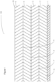
- FIG. 1 there is shown an air-permeable, non-woven structure, generally indicated 100, as formed in step (i) of the method of the present invention.
- a first layer 1 comprised of non-woven fibres is bonded, manufactured onto or otherwise attached to a second layer 2 at interface 6; a third layer 3 is bonded, manufactured onto or otherwise attached to the second layer 2 at interface 7; a fourth layer 4 is bonded, manufactured onto or otherwise attached to the third layer 3 at interface 8; and a fifth layer 5 is bonded, manufactured onto or otherwise attached to the fourth layer 4 at interface 9.
- the surface 10 of the fifth layer 5 in this embodiment is the uppermost surface.
- the fifth layer 5 comprises bi-component fibres in which the two components have differential melting temperatures.
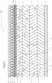
- FIG. 2 there is shown the air-permeable, non-woven structure described above with reference to Figure 1 , now generally indicated 200.
- Absorbent particles 11, 12, 13 and 14 of varying particle sizes have been dispersed onto the uppermost surface 10 of the fifth layer 5, as per step (ii) of the method of the present invention. Due to the relatively open structure of the surface of the fifth layer 5, some of the particles 11, 12, 13 and 14 have passed into the subsequent layers 2, 3, 4 and 5. Some of the absorbent particles have thus come to rest in layers where the void space within that specific layer allows free passage of the absorbent particles.
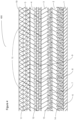
- FIG. 3 there is shown the air-permeable, non-woven structure described above with reference to Figures 1 and 2 , now generally indicated 300.
- the structure 300, and the dispersed absorbent particles 11, 12, 13 and 14 have now been exposed to a particle dissipation process as per step (iii) of the method of the present invention.
- the absorbent particles 11, 12, 13 and 14 have been de-agglomerated and as a result of the effect of the dissipation process have become located substantially below the uppermost surface 10 of the fifth layer 5 and have become substantially dispersed throughout the structure according to both the void space size within each of the individual layers 2, 3, 4 and 5 and the specific particle size distribution profile of the absorbent being dispersed.
- Particles 11, 12, 13 and 14 have come to rest substantially below the surface of the fifth layer 5; absorbent particles 11 are prevented from passing into the fourth layer 4 at interface 9 due to the restrictive spaces between the fibres that constitute the fourth layer 4; absorbent particles 12 are prevented from passing into the third layer 3 at interface 8 due to the restrictive spaces between the fibres that constitute the third layer 3; absorbent particles 13 are prevented from passing into the second layer 2 at interface 7 due to the restrictive spaces between the fibres that constitute the second layer 2; whilst the restrictive void spaces between the fibres that constitute layer 1 are too small to allow the passage of any of the absorbent particles, irrespective of their size.
- FIG. 4 there is shown the air-permeable, non-woven structure described above with reference to Figures 1 to 3 , now generally indicated 400, following the performance of a consolidation process, as per optional step (iv) of the method of the present invention.
- the consolidation process has been applied to the uppermost (fifth) layer 5 such that now dissipated particles 11, 12, 13 and 14 are prevented from exiting the air-permeable structure via the uppermost (fifth) layer 5 due to the consolidation of fibres in region 15 of the fifth layer 5.
- an absorbent particle and non-woven matrix emerging from method step (iv), as described above with reference to Figure 4 .
- the uppermost surface 10 of the fifth layer 5 has had absorbent particles dispersed upon it in a pre-determined pattern or shape 16.
- an portion 18 of the matrix 500 may be cut or otherwise extracted from the air permeable non-woven matrix 500 along path 17, such that the path of the cut line 17 is larger in size than the pre-determined pattern or shape 16.
- FIG. 6 there is shown an absorbent article generally indicated 600, following cutting or otherwise extracting the portion 18 of the particle and non-woven matrix 500 along path 17, as described above with reference to Figure 5 .
- FIG. 7 there is shown a process layout 700 for performing steps (ii) and (iii) of a first embodiment of the method of the present invention.
- Absorbent particles 11, 12, 13 and 14 are dispersed, as per step (ii), onto the surface of an air-permeable, non-woven structure 21, comprising layers 1, 2, 3, 4 and 5, by means of a controlled scattering device 19.
- the non-woven structure 21 is moved in the direction of arrow 23 across a base plate 24 whilst simultaneously a substantially vertically applied ultra-sonic force is applied, as per step (iii), at the interface 26 of an ultra-sonic device 22 causing the particles 11, 12, 13 and 14 to become entrained within the non-woven layers 25.
- FIG. 8 there is shown a comparative process layout 800 not belonging to the invetion.
- Absorbent particles 11, 12, 13 and 14 are dispersed, as per step (ii) onto the surface of an air-permeable, non-woven structure 21, comprising layers 1, 2, 3, 4 and 5 by means of a controlled scattering device 19.
- the non-woven layer 21 is moved in the direction of arrow 23 across a base plate 24 whilst simultaneously a substantially vertically applied low frequency vibration in the range of 10Hz to 200Hz is applied, as per step (iii), at the interface 27 of a low frequency vibration device 28 causing the particles 11, 12, 13 and 14 to become entrained within the non-woven layers 25.
- FIG. 9 there is shown a comparative process layout 900 not belonging to the invetion.
- Absorbent particles 11, 12, 13 and 14 are dispersed, as per step (ii), onto the surface of an air-permeable, non-woven structure 21, comprising layers 1, 2, 3, 4 and 5, by means of a controlled scattering device 19.
- the non-woven structure 21 is moved in the direction of arrow 23 across a perforated plate or membrane 30 whilst simultaneously a substantially vertically applied vacuum force 29 is applied, as per step (iii), from beneath the perforated plate or membrane 30 causing the particles 11, 12, 13 and 14 to become entrained within the non-woven layers 25.
- FIG. 10 there is shown a comparative process layout 1000 not belonging to the invention.
- Absorbent particles 11, 12, 13 and 14 are dispersed, as per step (ii) onto the surface of an air-permeable, non-woven an air-permeable, layers 1, 2, 3, 4 and 5, by means of a controlled scattering device 19.
- the non-woven structure 21 is moved in the direction of arrow 23 between an upper electrode device 31 and a lower electrode device 32, each electrode device having a dielectric plate 33 and 34 located between said electrode devices 31 and 32 and the target particles 11, 12, 13 and 14 together with the non-woven structure 21.
- the upper electrode device 31 is connected to a high voltage, alternating current generator via cable 37 whilst the lower electrode device 32 is connected to earth 35.
- the energy field generated between the upper electrode 31 and lower electrode 32 causes the powder to become excited and vibrate in a plane substantially normal to the plane of the dielectric plates 33 and 34 and become dissipated, as per step (iii), within the non-woven layers 25.
- a non-woven fabric structure was manufactured comprising five individual layers of varying void space dimensions between individual and groups of fibres. Each of the four lower layers were manufactured using a blend of polypropylene, polyethylene and polyester fibres in the ratio of 20%, 40% and 40% respectively.
- the construction of the entire non-woven structure was such that the lowermost layer or first layer (ADL) would not permit the entry into or passage through of any Super Absorbent Polymer (SAP) particles of less than 10 ⁇ m in minimum diameter. Effectively, this layer was manufactured to act as a physical barrier to the passage of any of the SAP to be processed within this entire example.
- ADL lowermost layer or first layer
- SAP Super Absorbent Polymer
- the next layer or second layer was manufactured to permit the entry of SAP particles in the range of 10 ⁇ m to 150 ⁇ m but not to allow the entry of or passage through of SAP particles of particle size greater than 150 ⁇ m.
- the next or third layer was manufactured to permit the entry of SAP particles in the range 10 ⁇ m to 400 ⁇ m but not to permit the entry of or passage through of SAP of particle size greater than 400 ⁇ m.
- the next or fourth layer was manufactured to permit the entry of SAP particles in the range 10 ⁇ m to 600 ⁇ m but not to permit the entry or passage through of SAP of particle size greater than 600 ⁇ m.
- the next or fifth layer was manufactured to permit the entry of SAP particles in the range 10 ⁇ m and above.
- the uppermost layer of the non-woven structure was manufactured from bi-component fibres in a side by side configuration from polyester and polyethylene.
- the method of manufacture of the non-woven substrate as a whole was a combination of conventional random carding, air through and needle punch processes.
- a sodium polyacrylate SAP of particle size distribution ranging between 40 ⁇ m to 850 ⁇ m commercially manufactured by a market leader in the hygiene materials supply market was mechanically dispersed onto the uppermost surface of the aforesaid high loft non-woven fabric at an areal dispersion rate of 325 gsm (gm -2 ) which in practice would equate to an amount of 13g in a typical infant diaper core.
- the SAP and non-woven fabric structure was then subjected to an external vibrating energy source of frequency 50Hz and amplitude 1.5mm to dissipate the SAP particles within the structure of the non-woven.
- the particles were caused to come to rest within the structure in a gradient manner according to the specific PSD of the SAP particles and the void space at a given location within the non-woven fabric structure.
- the uppermost layer of the non-woven fabric structure was then subjected to an external heat source provided by infra-red heating lamps, to cause the bi-component fibres in the uppermost layer of the structure to crimp as a result of differential expansion of each component of the bi-component fibres.
- a non-woven fabric structure was manufactured comprising five individual layers of varying void space dimensions between individual and groups of fibres. Each of the four lower layers were manufactured using a blend of polypropylene, polyethylene and polyester fibres in the ratio of 20%, 40% and 40% respectively.
- the construction of the non-woven structure was such that the lowermost layer or first layer (ADL) would not permit the entry into or passage through of any Super Absorbent Polymer particles (SAP) of less than 10 ⁇ m in minimum diameter. Effectively, this layer was manufactured to act as a physical barrier to the passage of any of the SAP to be processed within this example.
- ADL lowermost layer or first layer
- SAP Super Absorbent Polymer particles
- the next layer or second layer was manufactured to permit the entry of SAP particles in the range of 10 ⁇ m to 150 ⁇ m but not to allow the entry of or passage through of SAP of particle size greater than 150 ⁇ m.
- the next or third layer was manufactured to permit the entry of SAP particles in the range 10 ⁇ m to 400 ⁇ m but not to permit the entry of or passage through of SAP of particle size greater than 400 ⁇ m.
- the next or fourth layer was manufactured to permit the entry of SAP particles in the range 10 ⁇ m to 600 ⁇ m but not to permit the entry or passage through of SAP of particle size greater than 600 ⁇ m.
- the next or fifth layer was manufactured to permit the entry of SAP particles in the range 10 ⁇ m and above.
- the uppermost layer of the non-woven structure was manufactured from bi-component fibres in a side by side configuration from polyester and polyethylene.
- the method of manufacture of the non-woven substrate as a whole was a combination of conventional random carding, air through and needle punch processes.
- a sodium polyacrylate SAP of particle size distribution ranging between 40 ⁇ m to 850 ⁇ m commercially manufactured by a market leader in the hygiene materials supply market was mechanically dispersed onto the uppermost surface of the aforesaid high loft non-woven fabric at an areal dispersion rate of 325 gsm (gm -2 ) which in practice would equate to an amount of 13g in a typical infant diaper core.
- the SAP and non-woven fabric structure was then subjected to an alternating voltage energy field (AVEF) of 25kV and of frequency 50Hz between two opposed electrode plates placed 10mm apart along their longitudinal axis to excite the SAP particles such that the particles were made to vibrate in a direction normal to the opposed surfaces of the electrode plates, the vibration energy being sufficient to dissipate the SAP within the non-woven fabric structure such that no SAP remained on the uppermost surface of the non-woven fabric structure.
- AVEF alternating voltage energy field
- the entire non-woven structure and SAP matrix was subject to an air-through heating process such that the lower melting temperature component of the bi-component fibres that constitute the uppermost layer of the structure became soft and tacky such as to bond to adjacent individual and groups of fibres thereby entrapping the SAP dissipated within the uppermost layer and creating a physical barrier to those SAP particles dissipated within the adjacent and lower layer from passing out through the uppermost layer upon the entire matrix being subjected to agitation.
- a non-woven fabric structure was manufactured comprising five individual layers of varying void space dimensions between individual and groups of fibres. Each of the four lower layers were manufactured using a blend of polypropylene, polyethylene and polyester fibres in the ratio of 20%, 40% and 40% respectively.
- the construction of the entire non-woven structure was such that the lower most layer or first layer (ADL) would not permit the entry into or passage through of any Super Absorbent Polymer particles (SAP) of less than 10 ⁇ m in minimum diameter. Effectively, this layer was manufactured to act as a physical barrier to the passage of any of the SAP to be processed within this example.
- ADL lower most layer or first layer
- SAP Super Absorbent Polymer particles
- the next layer or second layer was manufactured to permit the entry into of SAP particles in the range of 10 ⁇ m to 150 ⁇ m but not to allow the entry of or passage through of SAP of particle size greater than 150 ⁇ m.
- the next or third layer was manufactured to permit the entry of SAP particles in the range 10 ⁇ m to 400 ⁇ m but not to permit the entry of or passage through of SAP of particle size greater than 400 ⁇ m.
- the next or fourth layer was manufactured to permit the entry of SAP particles in the range 10 ⁇ m to 600 ⁇ m but not to permit the entry or passage through of SAP of particle size greater than 600 ⁇ m.
- the next or fifth layer was manufactured to permit the entry of SAP particles in the range 10 ⁇ m and above.
- the uppermost layer of the non-woven structure was manufactured from bi-component fibres in a side by side configuration from polyester and polyethylene.
- the method of manufacture of the non-woven substrate as a whole was a combination of conventional random carding, air through and needle punch processes.
- a sodium polyacrylate SAP of particle size distribution ranging between 40 ⁇ m to 850 ⁇ m commercially manufactured by a market leader in the hygiene materials supply market was mechanically dispersed onto the uppermost surface of the aforesaid high loft non-woven fabric structure at an areal dispersion rate of 325 gsm (gm -2 ) which in practice would equate to an amount of 13g in a typical infant diaper core.
- the SAP and non-woven fabric structure was then subjected to a vacuum, applied from below the lowermost surface of the structure of greater than 1 bar in pressure such that the SAP particles dispersed upon the uppermost layer of the structure were drawn into the structure with the SAP particles coming to rest within a specific given layer dependent upon the given diameter of the SAP particle in question.
- a sixth layer of spun bonded polypropylene non-woven fabric of areal weight of 8 gsm (gm -2 ) was then attached to the uppermost surface of the SAP and non-woven fabric matrix by means of intermittent ultra-sonic welding such that the SAP particles now dissipated within the non-woven fabric structure were prohibited from egress via the uppermost layer of the structure.
- a non-woven fabric structure was manufactured comprising five individual layers of varying void space dimensions between individual and groups of fibres. Each of the four lower layers were manufactured using a blend of polypropylene, polyethylene and polyester fibres in the ratio of 20%, 40% and 40% respectively.
- the construction of the entire non-woven structure was such that the lower most layer or first layer (ADL) would not permit the entry into or passage through of any Super Absorbent Polymer particles (SAP) of less than 10 ⁇ m in minimum diameter. Effectively, this layer was manufactured to act as a physical barrier to the passage of any of the SAP to be processed within this example.
- ADL lower most layer or first layer
- SAP Super Absorbent Polymer particles
- the next layer or second layer was manufactured to permit the entry into of SAP particles in the range of 10 ⁇ m to 150 ⁇ m but would not allow the entry of or passage through of SAP of particle size greater than 150 ⁇ m.
- the next or third layer was manufactured to permit the entry of SAP particles in the range 10 ⁇ m to 400 ⁇ m but would not permit the entry of or passage through of SAP of particle size greater than 400 ⁇ m.
- the next or fourth layer was manufactured to permit the entry of SAP particles in the range 10 ⁇ m to 600 ⁇ m but would not permit the entry or passage through of SAP of particle size greater than 600 ⁇ m.
- the next or fifth layer was manufactured to permit the entry of SAP particles in the range 10 ⁇ m and above.
- the uppermost layer of the non-woven structure was manufactured from bi-component fibres in a side by side configuration from polyester and polyethylene.
- the method of manufacture of the non-woven substrate as a whole was a combination of conventional random carding, air through and needle punch processes.
- a sodium polyacrylate SAP of particle size distribution ranging between 40 ⁇ m to 850 ⁇ m) commercially manufactured by a market leader in the hygiene materials supply market was mechanically dispersed onto the uppermost surface of the aforesaid high loft non-woven fabric structure at an areal dispersion rate of 325 gsm (gm -2 ) which in practice would equate to an amount of 13g in a typical infant diaper core.
- the SAP and non-woven fabric structure was then subjected to an external vibrating energy source of frequency 50Hz and amplitude 1.5mm to dissipate the SAP particles within the structure of the non-woven fabric structure.
- the particles were caused to come to rest within the substrate in a gradient manner according to the specific PSD of the SAP particles and the void space at a given location within the cross-section of the entire non-woven fabric structure.
- a polyethylene film coated on one surface with a heat sensitive adhesive based on polyurethane chemistry, was bonded onto the uppermost surface of the uppermost layer such that the SAP particles now dissipated within the non-woven fabric structure were prohibited from egress via the uppermost layer of the substrate.
- a non-woven fabric structure was manufactured comprising five individual layers of varying void space dimensions between individual and groups of fibres. Each of the four lower layers were manufactured using a blend of polypropylene, polyethylene and polyester fibres in the ratio of 20%, 40% and 40% respectively.
- the construction of the entire non-woven structure was such that the lowermost layer or first layer (ADL) would not permit the entry into or passage through of any Super Absorbent Polymer particles (SAP) of less than 10 ⁇ m in minimum diameter. Effectively, this layer was manufactured to act as a physical barrier to the passage of any of the SAP to be processed within this example.
- ADL lowermost layer or first layer
- SAP Super Absorbent Polymer particles
- the next layer or second layer was manufactured to permit the entry into of SAP particles in the range of 10 ⁇ m to 150 ⁇ m but not to allow the entry of or passage through of SAP of particle size greater than 150 ⁇ m.
- the next or third layer was manufactured to permit the entry of SAP particles in the range 10 ⁇ m to 400 ⁇ m but not to permit the entry of or passage through of SAP of particle size greater than 400 ⁇ m.
- the next or fourth layer was manufactured to permit the entry of SAP particles in the range 10 ⁇ m to 600 ⁇ m but not to permit the entry or passage through of SAP of particle size greater than 600 ⁇ m.
- the next or fifth layer was manufactured to permit the entry of SAP particles in the range 10 ⁇ m and above.
- the uppermost layer of the non-woven structure was manufactured from bi-component fibres in a side by side configuration from polyester and polyethylene.
- the method of manufacture of the non-woven substrate as a whole was a combination of conventional random carding, air through and needle punch processes.
- a sodium polyacrylate Super Absorbent Polymer (SAP) of particle size distribution ranging between 40 ⁇ m to 850 ⁇ m commercially manufactured by a market leader in the hygiene materials supply market was mechanically dispersed onto the uppermost surface of the aforesaid high loft non-woven fabric at an areal dispersion rate of 325 gsm (gm -2 ) which in practice would equate to an amount of 13g in a typical infant diaper core.
- SAP sodium polyacrylate Super Absorbent Polymer
- the SAP now dispersed onto the uppermost surface of the non-woven fabric, was then subjected to an ultra-sonic energy source of 15kHz and with an amplitude of 90 microns via a suitably engineered sonotrode to excite the SAP particles such that the particles were made to vibrate in a direction normal to surface of the non-woven fabric structure, the vibration energy being sufficient to dissipate the SAP within the non-woven fabric structure such that no SAP remained on the uppermost surface of the non-woven fabric structure.
- the non-woven structure and SAP matrix was subject to an external heating process such that the lower melting temperature component of the bi-component fibres that constitute the uppermost layer of the structure became soft and tacky such as to bond to adjacent individual and groups of fibres thereby entrapping the SAP dissipated within the uppermost layer and creating a physical barrier to those SAP particles dissipated within the adjacent and lower layers from passing out through the uppermost layer upon the entire matrix being subjected to agitation.
Landscapes
- Engineering & Computer Science (AREA)
- Health & Medical Sciences (AREA)
- General Health & Medical Sciences (AREA)
- Public Health (AREA)
- Epidemiology (AREA)
- Biomedical Technology (AREA)
- Heart & Thoracic Surgery (AREA)
- Vascular Medicine (AREA)
- Life Sciences & Earth Sciences (AREA)
- Animal Behavior & Ethology (AREA)
- Veterinary Medicine (AREA)
- Manufacturing & Machinery (AREA)
- Textile Engineering (AREA)
- Physics & Mathematics (AREA)
- Fluid Mechanics (AREA)
- Chemical & Material Sciences (AREA)
- Materials Engineering (AREA)
- Absorbent Articles And Supports Therefor (AREA)
- Laminated Bodies (AREA)
- Nonwoven Fabrics (AREA)
Claims (15)
- Verfahren zum Auflösen und Einschließen von absorbierenden Partikeln innerhalb luftdurchlässiger Strukturen zur Verwendung bei der Herstellung von absorbierenden Artikeln, wobei das Verfahren die folgenden Schritte umfasst:(i) Herstellen einer luftdurchlässigen Vliesstruktur, umfassend zumindest eine erste, zweite und dritte Schicht von Vliesstoff, wobei jede der nummerierten Schichten (n) mit jeder darauffolgend nummerierten Schicht (n+1) verklebt, auf dieser hergestellt oder anderweitig mit dieser verbunden ist, und wobei Fasern in jeder der Schichten so angeordnet sind, um Leerräume dazwischen mit vorbestimmter Größe zu definieren, die einem gegebenen Größenverteilungsbereich der absorbierenden Partikel entsprechen;
und wobei die Leerräume in jeder der nummerierten Schicht (n) kleiner sind als die Leerräume in jeder darauffolgend nummerierten Schicht (n + 1);(ii) Dispergieren von absorbierenden Partikeln durch ein steuerbares mechanisches Mittel auf eine externe Oberfläche der am höchsten nummerierten Schicht der in Schritt (i) ausgebildeten luftdurchlässigen Vliesstruktur, wobei die absorbierenden Partikel einen vorbestimmten Partikelgrößenverteilungsbereich aufweisen;(iii) Zerstreuen der dispergierten absorbierenden Partikel innerhalb der luftdurchlässigen Vliesstruktur durch Anwenden einer externen Energiequelle, die auf die absorbierenden Partikel in eine Richtung einwirkt, die im Wesentlichen normal zur Ebene der externen Oberfläche der luftdurchlässigen Vliesstruktur steht,wobei die externe Energiequelle eine Ultraschallschwingungsquelle ist. - Verfahren nach Anspruch 1, wobei die Ultraschallschwingungsquelle in Schritt (iii) eine Frequenz im Bereich von zwischen 10 kHz und 50 kHz und eine Amplitude im Bereich von zwischen 5 µm und 500 µm erzeugt.
- Verfahren nach einem der vorangegangenen Ansprüche, wobei:(a) die am höchsten nummerierte Schicht der luftdurchlässigen Vliesstruktur Zweikomponentenfasern umfasst, wobei jede Komponente unterschiedliche Wärmeausdehnungseigenschaften aufweist;(b) jede Schicht der luftdurchlässigen Vliesstruktur, ausgenommen der ersten Schicht, Zweikomponentenfasern umfasst, wobei jede Komponente unterschiedliche Wärmeausdehnungseigenschaften aufweist; und/oder(c) zumindest eine der Schichten der luftdurchlässigen Vliesstruktur eine Mischung aus zumindest zwei verschiedenen Fasertypen mit unterschiedlichen Wärmeausdehnungseigenschaften umfasst.
- Verfahren nach Anspruch 3, das weiters nach dem Auflösungsschritt (iii) folgenden Schritt umfasst:
(iv) Aussetzen von zumindest einer Schicht der luftdurchlässigen Vliesstruktur einer externen Wärmequelle und danach Durchführen oder Zulassen des Abkühlens der zumindest einen Schicht, um die absorbierenden Partikel innerhalb der luftdurchlässigen Vliesstruktur einzuschließen. - Verfahren nach Anspruch 4, wobei die am höchsten nummerierte Schicht der luftdurchlässigen Vliesstruktur Zweikomponentenfasern umfasst, wobei jede Komponente verschiedene Wärmeausdehnungseigenschaften aufweist,
wobei in Schritt (iv) die am höchsten nummerierte Schicht der luftdurchlässigen Vliesstruktur einer externen Wärmequelle ausgesetzt wird, sodass sich die Komponenten in den Zweikomponentenfasern mit unterschiedlichen Raten beim Erhitzen ausdehnen und beim Kühlen zusammenziehen, wodurch bewirkt wird, dass sich die Fasern kräuseln oder wellen, wodurch die absorbierenden Partikel innerhalb der am höchsten nummerierten Schicht eingeschlossen werden. - Verfahren nach Anspruch 4, wobei jede Schicht der luftdurchlässigen Vliesstruktur, ausgenommen der ersten Schicht, Zweikomponentenfasern umfasst, wobei jede Komponente unterschiedliche Wärmeausdehnungseigenschaften aufweist,
wobei in Schritt (iv) alle Schichten der luftdurchlässigen Vliesstruktur einer externen Wärmequelle ausgesetzt werden, sodass sich die Komponenten in den Zweikomponentenfasern mit unterschiedlichen Raten beim Erhitzen ausdehnen und beim Kühlen zusammenziehen, wodurch bewirkt wird, dass sich die Faser kräuseln oder wellen, wodurch die absorbierenden Partikel innerhalb der luftdurchlässigen Vliesstruktur eingeschlossen werden. - Verfahren nach Anspruch 4, wobei zumindest eine der Schichten der luftdurchlässigen Vliesstruktur eine Mischung aus zumindest zwei verschiedenen Fasertypen mit unterschiedlichen Wärmeausdehnungseigenschaften umfasst,
wobei in Schritt (iv) alle Schichten der luftdurchlässigen Vliesstruktur einer externen Wärmequelle ausgesetzt werden, sodass sich die Fasern mit der niedrigsten Schmelztemperatur erweichen und klebrig werden, um an benachbarten absorbierenden Partikeln anzuhaften, wodurch die absorbierenden Partikel innerhalb der luftdurchlässigen Vliesstruktur eingeschlossen werden. - Verfahren nach einem der vorangegangenen Ansprüche, das ferner den folgenden Schritt umfasst:
(v) Schweißen, Verkleben oder anderweitiges Anbringen einer weiteren Schicht an der externen Oberfläche der am höchsten nummerierten Schicht der luftdurchlässigen Vliesstruktur, die die aufgelösten absorbierenden Partikel einschließt. - Verfahren nach Anspruch 8, wobei die weitere Schicht Folgendes ist:(a) eine Schicht aus einem Vliesstoff; oder(b) eine Polymerfolie.
- Verfahren nach einem der vorangegangenen Ansprüche, wobei die absorbierenden Partikel:(a) organisch sind; oder(b) Natriumpolyacrylat oder eine Polymermischung, die Natriumpolyacrylat einschließt, umfassen; und/oder(c) hydrophil sind.
- Verfahren nach einem der vorangegangenen Ansprüche, wobei die luftdurchlässige Vliesstruktur gemäß EN 13432 und/oder ASTM D6400 kompostierbar ist.
- Verfahren nach einem der vorangegangenen Ansprüche, wobei die resultierende luftdurchlässige Vliesstruktur und die Matrix aus absorbierenden Partikeln weiters durch die Anwendung von Wärme und/oder Druck vereinigt werden.
- Verfahren nach einem der vorangegangenen Ansprüche, wobei die resultierende luftdurchlässige Vliesstruktur und die Matrix aus absorbierenden Partikeln einem Lufterhitzungsverfahren unterzogen wird, um die Fasern durch Teilschmelzen zu vereinigen und gleichzeitig die teilgeschmolzenen Fasern an den eingeschlossenen absorbierenden Partikeln anzubringen, wodurch eine Diffusion der Partikeln aus der luftdurchlässigen Struktur verhindert wird.
- Verfahren nach einem der vorangegangenen Ansprüche, wobei in Schritt (ii) das Dispergieren der absorbierenden Partikeln über Folgendes erfolgt:(a) über die gesamte Oberfläche der luftdurchlässigen Vliesstruktur; oder(b) ausgewählte spezifische Bereiche der Oberfläche der luftdurchlässigen Vliesstruktur.
- Verfahren nach Anspruch 14, wobei das Dispergieren der absorbierenden Partikel über ausgewählte spezifische Bereiche der Oberfläche der luftdurchlässigen Vliesstruktur erfolgt,ferner umfassend den Schritt des Schneidens oder des anderweitigen Extrahierens der ausgewählten spezifischen Bereiche aus dem umgebenden luftdurchlässigen Substrat nach den Dispergierungs- (ii) und Zerstreungs- (iii) Schritten;gegebenenfalls ferner umfassend den anschließenden Schritt des Schweißens oder Versiegelns der Ränder der extrahierten spezifischen Bereiche auf einer Linie auf oder innerhalb von 30 mm der Schnittlinie.
Applications Claiming Priority (2)
| Application Number | Priority Date | Filing Date | Title |
|---|---|---|---|
| GBGB1423274.8A GB201423274D0 (en) | 2014-12-28 | 2014-12-28 | Particle entrained air permeable structures |
| PCT/GB2015/052746 WO2016108039A1 (en) | 2014-12-28 | 2015-09-23 | Particle entrained air-permeable structures |
Publications (3)
| Publication Number | Publication Date |
|---|---|
| EP3236909A1 EP3236909A1 (de) | 2017-11-01 |
| EP3236909B1 true EP3236909B1 (de) | 2024-12-11 |
| EP3236909C0 EP3236909C0 (de) | 2024-12-11 |
Family
ID=52471562
Family Applications (1)
| Application Number | Title | Priority Date | Filing Date |
|---|---|---|---|
| EP15787270.6A Active EP3236909B1 (de) | 2014-12-28 | 2015-09-23 | Luftdurchlässige strukturen mit mitgeführten partikeln |
Country Status (8)
| Country | Link |
|---|---|
| US (1) | US20170348157A1 (de) |
| EP (1) | EP3236909B1 (de) |
| JP (1) | JP2018506395A (de) |
| CN (1) | CN107109731A (de) |
| BR (1) | BR112017013952A2 (de) |
| GB (1) | GB201423274D0 (de) |
| MX (1) | MX2017008574A (de) |
| WO (1) | WO2016108039A1 (de) |
Families Citing this family (16)
| Publication number | Priority date | Publication date | Assignee | Title |
|---|---|---|---|---|
| EP3563921A4 (de) * | 2016-12-27 | 2020-07-22 | JDC Corporation | Formkörper mit geschichtetem doppelhydroxid und verfahren zur herstellung davon |
| US20180221618A1 (en) * | 2017-02-03 | 2018-08-09 | Lunatussin, LLC | Inhalation Therapy Device |
| EP3466387B1 (de) * | 2017-10-09 | 2023-09-27 | Drylock Technologies NV | Verfahren und vorrichtung zur herstellung einer absorptionsstruktur |
| EP3768209B1 (de) | 2018-03-22 | 2025-07-16 | DSG Technology Holdings Ltd. | Saugfähiger einwegartikel und saugfähiger kernverbund |
| CN108670556A (zh) * | 2018-06-07 | 2018-10-19 | 上海柔亚尔卫生材料有限公司 | 一种具有阶梯密度的复合芯体及其制备方法和应用 |
| ES2948646T3 (es) * | 2018-07-19 | 2023-09-15 | Twe Meulebeke | Estructura de no tejido multicapa para su uso como componente de artículos absorbentes desechables |
| MY208382A (en) * | 2018-12-17 | 2025-05-05 | Dsg Technology Holdings Ltd | Absorbent cores with enhanced fit and absorbency |
| US12042568B2 (en) | 2020-04-22 | 2024-07-23 | The Procter & Gamble Company | Adhesive for an absorbent article |
| CN111563321B (zh) * | 2020-04-23 | 2024-03-29 | 华南理工大学 | 基于pcisph由物理驱动的织物水含量仿真可视化方法 |
| CZ2020257A3 (cs) * | 2020-05-09 | 2021-11-18 | Pfnonwovens Holding S.R.O. | Netkaná textilní struktura pro absorpční výrobky a absorpční výrobek zahrnující takovouto netkanou textilní strukturu |
| GB202007392D0 (en) | 2020-05-19 | 2020-07-01 | Patchett Kim | Anti-viral fabric |
| EP4474559A3 (de) * | 2021-12-03 | 2025-02-26 | Ontex BV | Umweltfreundlicher saugfähiger artikel und herstellungsverfahren dafür |
| EP4190287B1 (de) * | 2021-12-03 | 2024-10-30 | Ontex BV | Umweltfreundlicher absorbierender artikel und verfahren zu seiner herstellung |
| DE102022102085B3 (de) | 2022-01-28 | 2023-02-16 | Optimum Technology IP LLC | Vliesaggregat und Verfahren zur Erzeugung eines Vliesaggregates |
| DE102022102084B3 (de) | 2022-01-28 | 2023-02-16 | Optimum Technology IP LLC | Vliesaggregat und Verfahren zur Erzeugung eines Vliesaggregates |
| CN114617713A (zh) * | 2022-03-21 | 2022-06-14 | 北京化工大学 | 一种单向导湿纸尿裤芯体 |
Citations (9)
| Publication number | Priority date | Publication date | Assignee | Title |
|---|---|---|---|---|
| WO1995008353A1 (en) | 1993-09-22 | 1995-03-30 | Mölnlycke AB | A superabsorbent fibre or nonwoven material, a method for its manufacture, and an absorbent article comprising the superabsorbent fibre or nonwoven material |
| WO2000029655A1 (en) | 1998-11-13 | 2000-05-25 | Kimberly-Clark Worldwide, Inc. | Bicomponent nonwoven webs containing adhesive and a third component |
| US20030018313A1 (en) | 1999-12-16 | 2003-01-23 | Tanzer Richard Warren | Absorbent structure and method |
| FR2866578A1 (fr) | 2004-02-23 | 2005-08-26 | Agro Fibres Technologies Plast | Nouveau media poreux : alveolaires, mousses, tissus, feutres, et analogues, ameliores par des poudres organiques ou minerales incorporees, procede d'incorporation par ultra-sons, sonde adaptee et leurs applications |
| EP1870067A1 (de) | 2005-04-01 | 2007-12-26 | Kao Corporation | Saugfähiger artikel |
| EP1920744A1 (de) | 2005-08-29 | 2008-05-14 | Kao Corporation | Saugfähiges blatt |
| WO2013153235A1 (en) | 2012-04-13 | 2013-10-17 | Libeltex | Unitary absorbent structures comprising an absorbent core and/or an acquisition and dispersion layer for absorbent articles |
| GB2504783A (en) | 2012-06-29 | 2014-02-12 | Concepts For Success C4S | Sandwich structure containing free flowing material |
| US20140155853A1 (en) | 2012-11-09 | 2014-06-05 | Curt G. Joa, Inc. | Apparatus and methods for forming laminates containing additive matter |
Family Cites Families (9)
| Publication number | Priority date | Publication date | Assignee | Title |
|---|---|---|---|---|
| US4952550A (en) * | 1989-03-09 | 1990-08-28 | Micro Vesicular Systems, Inc. | Particulate absorbent material |
| JP4124938B2 (ja) * | 2000-02-01 | 2008-07-23 | 株式会社日本吸収体技術研究所 | 水崩壊性高吸水性複合体及び吸収体物品 |
| US20020102392A1 (en) * | 2000-12-28 | 2002-08-01 | Kimberly-Clark Worldwide, Inc. | Flexible laminate structures having enclosed discrete regions of a material |
| JP3980043B2 (ja) * | 2005-04-01 | 2007-09-19 | 花王株式会社 | 吸収性物品 |
| JP5008383B2 (ja) * | 2006-11-27 | 2012-08-22 | 花王株式会社 | 吸収性物品 |
| JP2008132055A (ja) * | 2006-11-27 | 2008-06-12 | Kao Corp | 吸収体 |
| WO2009088648A1 (en) * | 2007-12-31 | 2009-07-16 | 3M Innovative Properties Company | Composite non-woven fibrous webs having continuous particulate phase and methods of making and using the same |
| JP2013252331A (ja) * | 2012-06-08 | 2013-12-19 | Unicharm Corp | 吸収体及び該吸収体を備える吸収性物品 |
| JP2014079566A (ja) * | 2012-09-30 | 2014-05-08 | Uni Charm Corp | 吸収性物品 |
-
2014
- 2014-12-28 GB GBGB1423274.8A patent/GB201423274D0/en not_active Ceased
-
2015
- 2015-09-23 US US15/539,470 patent/US20170348157A1/en not_active Abandoned
- 2015-09-23 MX MX2017008574A patent/MX2017008574A/es unknown
- 2015-09-23 WO PCT/GB2015/052746 patent/WO2016108039A1/en not_active Ceased
- 2015-09-23 CN CN201580071450.2A patent/CN107109731A/zh active Pending
- 2015-09-23 BR BR112017013952A patent/BR112017013952A2/pt not_active Application Discontinuation
- 2015-09-23 JP JP2017552243A patent/JP2018506395A/ja active Pending
- 2015-09-23 EP EP15787270.6A patent/EP3236909B1/de active Active
Patent Citations (10)
| Publication number | Priority date | Publication date | Assignee | Title |
|---|---|---|---|---|
| WO1995008353A1 (en) | 1993-09-22 | 1995-03-30 | Mölnlycke AB | A superabsorbent fibre or nonwoven material, a method for its manufacture, and an absorbent article comprising the superabsorbent fibre or nonwoven material |
| WO2000029655A1 (en) | 1998-11-13 | 2000-05-25 | Kimberly-Clark Worldwide, Inc. | Bicomponent nonwoven webs containing adhesive and a third component |
| US20030018313A1 (en) | 1999-12-16 | 2003-01-23 | Tanzer Richard Warren | Absorbent structure and method |
| FR2866578A1 (fr) | 2004-02-23 | 2005-08-26 | Agro Fibres Technologies Plast | Nouveau media poreux : alveolaires, mousses, tissus, feutres, et analogues, ameliores par des poudres organiques ou minerales incorporees, procede d'incorporation par ultra-sons, sonde adaptee et leurs applications |
| EP1870067A1 (de) | 2005-04-01 | 2007-12-26 | Kao Corporation | Saugfähiger artikel |
| EP1920744A1 (de) | 2005-08-29 | 2008-05-14 | Kao Corporation | Saugfähiges blatt |
| WO2013153235A1 (en) | 2012-04-13 | 2013-10-17 | Libeltex | Unitary absorbent structures comprising an absorbent core and/or an acquisition and dispersion layer for absorbent articles |
| WO2013152809A1 (en) | 2012-04-13 | 2013-10-17 | Libeltex | Unitary absorbent structures comprising an absorbent core and/or an acquisition and dispersion layer for absorbent articles |
| GB2504783A (en) | 2012-06-29 | 2014-02-12 | Concepts For Success C4S | Sandwich structure containing free flowing material |
| US20140155853A1 (en) | 2012-11-09 | 2014-06-05 | Curt G. Joa, Inc. | Apparatus and methods for forming laminates containing additive matter |
Non-Patent Citations (1)
| Title |
|---|
| ALBRECHT, FUCHS, KITTELMANN: "Nonwoven Fabrics", 1 January 2003, WILEY-VCH , Weinheim , ISBN: 3-527-30406-1, article W. ALBRECHT: "Fibrous Material", pages: 15 - 85, XP009563460, DOI: 10.1002/3527603344.ch1 |
Also Published As
| Publication number | Publication date |
|---|---|
| CN107109731A (zh) | 2017-08-29 |
| EP3236909A1 (de) | 2017-11-01 |
| MX2017008574A (es) | 2018-04-26 |
| BR112017013952A2 (pt) | 2018-01-02 |
| GB201423274D0 (en) | 2015-02-11 |
| EP3236909C0 (de) | 2024-12-11 |
| US20170348157A1 (en) | 2017-12-07 |
| WO2016108039A1 (en) | 2016-07-07 |
| JP2018506395A (ja) | 2018-03-08 |
Similar Documents
| Publication | Publication Date | Title |
|---|---|---|
| EP3236909B1 (de) | Luftdurchlässige strukturen mit mitgeführten partikeln | |
| KR100732074B1 (ko) | 입자를 함유하는 멜트블로운 웹 | |
| EP1993501B1 (de) | Saugfähige vliesfasermatten und herstellungsverfahren dafür | |
| CN100491620C (zh) | 一种功能微粒改性熔喷非织造布的制备方法及制造设备 | |
| JP2005514534A (ja) | コーティングが施された超吸収体を含む不織ウェブ | |
| CN108473357B (zh) | 用于形成熔体成型无机纤维的器械和方法 | |
| TR201808524T4 (tr) | Lif içeren ve/veya partikül içeren dokunmamış materyeli üretmeye yönelik proses ve aparat. | |
| KR20180095492A (ko) | 다기능성의 마스크 | |
| JP6550289B2 (ja) | 不織布及びその製造方法並びに吸収性物品 | |
| KR101894892B1 (ko) | ?기트 및 내추럴 플러렌을 포함하는 마스크 | |
| CA2256422C (en) | Method for distributing molecular sieve powder | |
| KR101992657B1 (ko) | 다기능성의 자동차용 공기정화필터 | |
| KR101888859B1 (ko) | ?기트 및 내추럴 플러렌을 포함하는 자동차용 공기정화필터 | |
| KR101818172B1 (ko) | 기트 및 내추럴 플러렌을 포함하는 일회용 흡수제품 | |
| JP7546129B2 (ja) | タングステンシート及び放射線防護服 | |
| JP4178997B2 (ja) | 機能性繊維集合体及びそれを用いた成形体 | |
| KR101927794B1 (ko) | 다기능성의 일회용 체액 흡수제품 | |
| CN101341283B (zh) | 具有增强透气性的膨体复合材料 | |
| KR101820858B1 (ko) | 일회용 체액 흡수제품 | |
| CN114009882A (zh) | 一种具有电容特征的新型物理抗病毒防护口罩 | |
| EP3676206B1 (de) | Luftunterstütztes teilchenverabreichungssystem | |
| JP7275017B2 (ja) | 吸収シート製造装置および吸収シート製造方法 | |
| KR101975860B1 (ko) | 다기능성의 공기조화장치 | |
| Qian et al. | The method of producing nanomaterials and melt blown nonwovens composites | |
| WO2021198320A1 (en) | Face mask |
Legal Events
| Date | Code | Title | Description |
|---|---|---|---|
| STAA | Information on the status of an ep patent application or granted ep patent |
Free format text: STATUS: THE INTERNATIONAL PUBLICATION HAS BEEN MADE |
|
| PUAI | Public reference made under article 153(3) epc to a published international application that has entered the european phase |
Free format text: ORIGINAL CODE: 0009012 |
|
| STAA | Information on the status of an ep patent application or granted ep patent |
Free format text: STATUS: REQUEST FOR EXAMINATION WAS MADE |
|
| 17P | Request for examination filed |
Effective date: 20170628 |
|
| AK | Designated contracting states |
Kind code of ref document: A1 Designated state(s): AL AT BE BG CH CY CZ DE DK EE ES FI FR GB GR HR HU IE IS IT LI LT LU LV MC MK MT NL NO PL PT RO RS SE SI SK SM TR |
|
| AX | Request for extension of the european patent |
Extension state: BA ME |
|
| RIN1 | Information on inventor provided before grant (corrected) |
Inventor name: PATCHETT, KIM |
|
| DAV | Request for validation of the european patent (deleted) | ||
| DAX | Request for extension of the european patent (deleted) | ||
| STAA | Information on the status of an ep patent application or granted ep patent |
Free format text: STATUS: EXAMINATION IS IN PROGRESS |
|
| 17Q | First examination report despatched |
Effective date: 20190222 |
|
| TPAC | Observations filed by third parties |
Free format text: ORIGINAL CODE: EPIDOSNTIPA |
|
| GRAP | Despatch of communication of intention to grant a patent |
Free format text: ORIGINAL CODE: EPIDOSNIGR1 |
|
| STAA | Information on the status of an ep patent application or granted ep patent |
Free format text: STATUS: GRANT OF PATENT IS INTENDED |
|
| INTG | Intention to grant announced |
Effective date: 20200515 |
|
| RAP1 | Party data changed (applicant data changed or rights of an application transferred) |
Owner name: OPTIMUM TECHNOLOGY INTELLECTUAL PROPERTY LLC |
|
| RIN1 | Information on inventor provided before grant (corrected) |
Inventor name: OPTIMUM TECHNOLOGY INTELLECTUAL PROPERTY LLC |
|
| GRAJ | Information related to disapproval of communication of intention to grant by the applicant or resumption of examination proceedings by the epo deleted |
Free format text: ORIGINAL CODE: EPIDOSDIGR1 |
|
| STAA | Information on the status of an ep patent application or granted ep patent |
Free format text: STATUS: EXAMINATION IS IN PROGRESS |
|
| INTC | Intention to grant announced (deleted) | ||
| GRAP | Despatch of communication of intention to grant a patent |
Free format text: ORIGINAL CODE: EPIDOSNIGR1 |
|
| STAA | Information on the status of an ep patent application or granted ep patent |
Free format text: STATUS: GRANT OF PATENT IS INTENDED |
|
| INTG | Intention to grant announced |
Effective date: 20210222 |
|
| GRAJ | Information related to disapproval of communication of intention to grant by the applicant or resumption of examination proceedings by the epo deleted |
Free format text: ORIGINAL CODE: EPIDOSDIGR1 |
|
| STAA | Information on the status of an ep patent application or granted ep patent |
Free format text: STATUS: EXAMINATION IS IN PROGRESS |
|
| INTC | Intention to grant announced (deleted) | ||
| GRAP | Despatch of communication of intention to grant a patent |
Free format text: ORIGINAL CODE: EPIDOSNIGR1 |
|
| STAA | Information on the status of an ep patent application or granted ep patent |
Free format text: STATUS: GRANT OF PATENT IS INTENDED |
|
| INTG | Intention to grant announced |
Effective date: 20211206 |
|
| GRAJ | Information related to disapproval of communication of intention to grant by the applicant or resumption of examination proceedings by the epo deleted |
Free format text: ORIGINAL CODE: EPIDOSDIGR1 |
|
| STAA | Information on the status of an ep patent application or granted ep patent |
Free format text: STATUS: EXAMINATION IS IN PROGRESS |
|
| GRAP | Despatch of communication of intention to grant a patent |
Free format text: ORIGINAL CODE: EPIDOSNIGR1 |
|
| STAA | Information on the status of an ep patent application or granted ep patent |
Free format text: STATUS: GRANT OF PATENT IS INTENDED |
|
| INTC | Intention to grant announced (deleted) | ||
| INTG | Intention to grant announced |
Effective date: 20220826 |
|
| GRAJ | Information related to disapproval of communication of intention to grant by the applicant or resumption of examination proceedings by the epo deleted |
Free format text: ORIGINAL CODE: EPIDOSDIGR1 |
|
| STAA | Information on the status of an ep patent application or granted ep patent |
Free format text: STATUS: EXAMINATION IS IN PROGRESS |
|
| INTC | Intention to grant announced (deleted) | ||
| GRAP | Despatch of communication of intention to grant a patent |
Free format text: ORIGINAL CODE: EPIDOSNIGR1 |
|
| STAA | Information on the status of an ep patent application or granted ep patent |
Free format text: STATUS: GRANT OF PATENT IS INTENDED |
|
| INTG | Intention to grant announced |
Effective date: 20230602 |
|
| GRAJ | Information related to disapproval of communication of intention to grant by the applicant or resumption of examination proceedings by the epo deleted |
Free format text: ORIGINAL CODE: EPIDOSDIGR1 |
|
| STAA | Information on the status of an ep patent application or granted ep patent |
Free format text: STATUS: EXAMINATION IS IN PROGRESS |
|
| INTC | Intention to grant announced (deleted) | ||
| GRAP | Despatch of communication of intention to grant a patent |
Free format text: ORIGINAL CODE: EPIDOSNIGR1 |
|
| STAA | Information on the status of an ep patent application or granted ep patent |
Free format text: STATUS: GRANT OF PATENT IS INTENDED |
|
| INTG | Intention to grant announced |
Effective date: 20240408 |
|
| GRAS | Grant fee paid |
Free format text: ORIGINAL CODE: EPIDOSNIGR3 |
|
| GRAA | (expected) grant |
Free format text: ORIGINAL CODE: 0009210 |
|
| STAA | Information on the status of an ep patent application or granted ep patent |
Free format text: STATUS: THE PATENT HAS BEEN GRANTED |
|
| AK | Designated contracting states |
Kind code of ref document: B1 Designated state(s): AL AT BE BG CH CY CZ DE DK EE ES FI FR GB GR HR HU IE IS IT LI LT LU LV MC MK MT NL NO PL PT RO RS SE SI SK SM TR |
|
| REG | Reference to a national code |
Ref country code: GB Ref legal event code: FG4D |
|
| RIN1 | Information on inventor provided before grant (corrected) |
Inventor name: PATCHETT, KIM |
|
| REG | Reference to a national code |
Ref country code: CH Ref legal event code: EP |
|
| REG | Reference to a national code |
Ref country code: IE Ref legal event code: FG4D |
|
| REG | Reference to a national code |
Ref country code: DE Ref legal event code: R096 Ref document number: 602015090621 Country of ref document: DE |
|
| U01 | Request for unitary effect filed |
Effective date: 20250113 |
|
| U07 | Unitary effect registered |
Designated state(s): AT BE BG DE DK EE FI FR IT LT LU LV MT NL PT RO SE SI Effective date: 20250117 |
|
| PG25 | Lapsed in a contracting state [announced via postgrant information from national office to epo] |
Ref country code: HR Free format text: LAPSE BECAUSE OF FAILURE TO SUBMIT A TRANSLATION OF THE DESCRIPTION OR TO PAY THE FEE WITHIN THE PRESCRIBED TIME-LIMIT Effective date: 20241211 |
|
| PG25 | Lapsed in a contracting state [announced via postgrant information from national office to epo] |
Ref country code: ES Free format text: LAPSE BECAUSE OF FAILURE TO SUBMIT A TRANSLATION OF THE DESCRIPTION OR TO PAY THE FEE WITHIN THE PRESCRIBED TIME-LIMIT Effective date: 20241211 |
|
| PG25 | Lapsed in a contracting state [announced via postgrant information from national office to epo] |
Ref country code: NO Free format text: LAPSE BECAUSE OF FAILURE TO SUBMIT A TRANSLATION OF THE DESCRIPTION OR TO PAY THE FEE WITHIN THE PRESCRIBED TIME-LIMIT Effective date: 20250311 |
|
| PG25 | Lapsed in a contracting state [announced via postgrant information from national office to epo] |
Ref country code: GR Free format text: LAPSE BECAUSE OF FAILURE TO SUBMIT A TRANSLATION OF THE DESCRIPTION OR TO PAY THE FEE WITHIN THE PRESCRIBED TIME-LIMIT Effective date: 20250312 |
|
| PG25 | Lapsed in a contracting state [announced via postgrant information from national office to epo] |
Ref country code: RS Free format text: LAPSE BECAUSE OF FAILURE TO SUBMIT A TRANSLATION OF THE DESCRIPTION OR TO PAY THE FEE WITHIN THE PRESCRIBED TIME-LIMIT Effective date: 20250311 |
|
| PG25 | Lapsed in a contracting state [announced via postgrant information from national office to epo] |
Ref country code: SM Free format text: LAPSE BECAUSE OF FAILURE TO SUBMIT A TRANSLATION OF THE DESCRIPTION OR TO PAY THE FEE WITHIN THE PRESCRIBED TIME-LIMIT Effective date: 20241211 |
|
| PG25 | Lapsed in a contracting state [announced via postgrant information from national office to epo] |
Ref country code: PL Free format text: LAPSE BECAUSE OF FAILURE TO SUBMIT A TRANSLATION OF THE DESCRIPTION OR TO PAY THE FEE WITHIN THE PRESCRIBED TIME-LIMIT Effective date: 20241211 |
|
| PG25 | Lapsed in a contracting state [announced via postgrant information from national office to epo] |
Ref country code: IS Free format text: LAPSE BECAUSE OF FAILURE TO SUBMIT A TRANSLATION OF THE DESCRIPTION OR TO PAY THE FEE WITHIN THE PRESCRIBED TIME-LIMIT Effective date: 20250411 |
|
| PG25 | Lapsed in a contracting state [announced via postgrant information from national office to epo] |
Ref country code: SK Free format text: LAPSE BECAUSE OF FAILURE TO SUBMIT A TRANSLATION OF THE DESCRIPTION OR TO PAY THE FEE WITHIN THE PRESCRIBED TIME-LIMIT Effective date: 20241211 |
|
| PG25 | Lapsed in a contracting state [announced via postgrant information from national office to epo] |
Ref country code: CZ Free format text: LAPSE BECAUSE OF FAILURE TO SUBMIT A TRANSLATION OF THE DESCRIPTION OR TO PAY THE FEE WITHIN THE PRESCRIBED TIME-LIMIT Effective date: 20241211 |
|
| PLBI | Opposition filed |
Free format text: ORIGINAL CODE: 0009260 |
|
| PLAX | Notice of opposition and request to file observation + time limit sent |
Free format text: ORIGINAL CODE: EPIDOSNOBS2 |
|
| 26 | Opposition filed |
Opponent name: TWE MEULEBEKE Effective date: 20250909 |
|
| PGFP | Annual fee paid to national office [announced via postgrant information from national office to epo] |
Ref country code: GB Payment date: 20250924 Year of fee payment: 11 |
|
| U20 | Renewal fee for the european patent with unitary effect paid |
Year of fee payment: 11 Effective date: 20250916 |