EP3236882B1 - Appareil d'administration, système et procédés associés - Google Patents
Appareil d'administration, système et procédés associés Download PDFInfo
- Publication number
- EP3236882B1 EP3236882B1 EP15871354.5A EP15871354A EP3236882B1 EP 3236882 B1 EP3236882 B1 EP 3236882B1 EP 15871354 A EP15871354 A EP 15871354A EP 3236882 B1 EP3236882 B1 EP 3236882B1
- Authority
- EP
- European Patent Office
- Prior art keywords
- delivery
- substance
- medication
- section
- delivery section
- Prior art date
- Legal status (The legal status is an assumption and is not a legal conclusion. Google has not performed a legal analysis and makes no representation as to the accuracy of the status listed.)
- Active
Links
Images


Classifications
-
- A—HUMAN NECESSITIES
- A61—MEDICAL OR VETERINARY SCIENCE; HYGIENE
- A61D—VETERINARY INSTRUMENTS, IMPLEMENTS, TOOLS, OR METHODS
- A61D7/00—Devices or methods for introducing solid, liquid, or gaseous remedies or other materials into or onto the bodies of animals
-
- A—HUMAN NECESSITIES
- A61—MEDICAL OR VETERINARY SCIENCE; HYGIENE
- A61M—DEVICES FOR INTRODUCING MEDIA INTO, OR ONTO, THE BODY; DEVICES FOR TRANSDUCING BODY MEDIA OR FOR TAKING MEDIA FROM THE BODY; DEVICES FOR PRODUCING OR ENDING SLEEP OR STUPOR
- A61M2205/00—General characteristics of the apparatus
- A61M2205/50—General characteristics of the apparatus with microprocessors or computers
-
- A—HUMAN NECESSITIES
- A61—MEDICAL OR VETERINARY SCIENCE; HYGIENE
- A61M—DEVICES FOR INTRODUCING MEDIA INTO, OR ONTO, THE BODY; DEVICES FOR TRANSDUCING BODY MEDIA OR FOR TAKING MEDIA FROM THE BODY; DEVICES FOR PRODUCING OR ENDING SLEEP OR STUPOR
- A61M5/00—Devices for bringing media into the body in a subcutaneous, intra-vascular or intramuscular way; Accessories therefor, e.g. filling or cleaning devices, arm-rests
- A61M5/178—Syringes
- A61M5/20—Automatic syringes, e.g. with automatically actuated piston rod, with automatic needle injection, filling automatically
- A61M5/204—Automatic syringes, e.g. with automatically actuated piston rod, with automatic needle injection, filling automatically connected to external reservoirs for multiple refilling
-
- G—PHYSICS
- G16—INFORMATION AND COMMUNICATION TECHNOLOGY [ICT] SPECIALLY ADAPTED FOR SPECIFIC APPLICATION FIELDS
- G16H—HEALTHCARE INFORMATICS, i.e. INFORMATION AND COMMUNICATION TECHNOLOGY [ICT] SPECIALLY ADAPTED FOR THE HANDLING OR PROCESSING OF MEDICAL OR HEALTHCARE DATA
- G16H20/00—ICT specially adapted for therapies or health-improving plans, e.g. for handling prescriptions, for steering therapy or for monitoring patient compliance
- G16H20/10—ICT specially adapted for therapies or health-improving plans, e.g. for handling prescriptions, for steering therapy or for monitoring patient compliance relating to drugs or medications, e.g. for ensuring correct administration to patients
- G16H20/17—ICT specially adapted for therapies or health-improving plans, e.g. for handling prescriptions, for steering therapy or for monitoring patient compliance relating to drugs or medications, e.g. for ensuring correct administration to patients delivered via infusion or injection
Definitions
- the invention relates to a medication or substance delivery apparatus.
- Livestock such as cattle, often need to be administered medication substances such as vaccinations or vitamins.
- medication substances such as vaccinations or vitamins.
- such medication substances are administered to the animal via a drench gun or injection gun having a needle to inject the medication substance into the animal.
- semi-automatic delivery devices or guns which, to some extent, attempt to measure and record doses of medication delivered to an animal.
- these devices include a gun that is configured to deliver a pre-determined dose of a medication substance to an animal.
- the gun may include a computer system or the like to record the delivered dose.
- the invention disclosed herein seeks to overcome one or more of the above-identified problems or at least provide a useful alternative.
- WO 2014107766 discloses an apparatus for discharging a dose of a fluid substance to an animal.
- a hand held apparatus a removable delivery section and a method for determining a compatibility of a removable delivery section with a drive section as defined in the appended claims.
- a hand held apparatus for delivering a substance to an animal, the apparatus including: a removable delivery section including a delivery arrangement adapted to deliver the substance to the animal; and a drive section including a drive arrangement adapted to actuate the delivery arrangement in a coupled condition in which the removable delivery section is coupled to the drive section, wherein the delivery section includes an electronic device adapted to communicate with a control system associated with at least the drive section in the coupled condition, the electronic device being configurable so to be readable by the control system such that the control system is able to identify and operate the removable delivery section.
- the electronic device is configurable to store at least one of configuration information and substance type information.
- the electronic device includes memory configurable to store the at least one of the configuration information and substance type information.
- the control system includes a processor carried by at least one of the drive section and an external computing device, the processor being configurable to read the at least one of configuration information and substance type information thereby enabling the drive section, in association with the control system, to identify and operate the delivery section.
- the control system includes a processor carried the drive section, the processor being configurable to read the at least one of configuration information and substance type information thereby enabling the drive section to identify and operate the delivery section.
- the delivery section and drive section include corresponding electrical terminals arranged to electrically communicate the memory of the electronic device with the processor carried by the drive section.
- the delivery arrangement includes a substance plunger and the drive arrangement includes a driving part adapted to move the substance plunger in the coupled condition.
- the delivery arrangement includes a delivery coupling part coupled to the substance plunger and the drive arrangement includes a drive coupling part coupled to the driving part, wherein the delivery coupling part and driving coupling part are arranged to be releasably coupled in the coupled condition such that movement of the driving part causes like-wise movement of the substance plunger.
- the delivery arrangement includes a substance reservoir and a substance piston received within the substance reservoir, and wherein the drive arrangement includes a driving part adapted to couple with the substance piston in the coupled condition so as to move the substance piston thereby moving the substance reservoir between an expanded state, in which the substance is locatable within the substance reservoir, and a contracted state in which the substance is at least partially expellable from the substance reservoir.
- a delivery section for removable coupling with a drive section to form a hand held apparatus for delivering a substance to an animal
- the delivery section including a delivery arrangement adapted to deliver the substance to the animal and the drive section including a drive arrangement adapted to actuate the delivery arrangement in a coupled condition in which the removable delivery section is coupled to the drive section
- the delivery section includes an electronic identifier adapted to communicate with a control system associated with at least the drive section in the coupled condition, the electronic identifier adapted to be readable by the control system such that the control system is able to identify and operate the removable delivery section.
- the electronic identifier includes memory configurable to store at least one of the configuration data and substance type data.
- the delivery section includes electrical terminals arranged to electrically communicate the memory of the electronic device with a processor carried by the drive section.
- the memory is electrically erasable programmable read-only memory.
- the electronic identifier includes memory configurable to store data readable by the control system to determine if the delivery section is in one of a substance configured state and a non-substance configured state.
- the delivery section includes: a substance cylinder in which a substance plunger is received, the substance plunger being coupled in the coupled condition with the drive arrangement; a substance inlet in fluid communication with the delivery cylinder through which the substance is selectively introducible into the delivery cylinder; and a delivery part through which the substance is selectively dischargeable to the animal.
- the delivery section includes an antenna configured to read an associated identification device of the animal.
- a system for delivering a dose of a substance to an animal including: an interchangeable delivery section including a delivery arrangement adapted to deliver the substance to the animal and an electronic device; a drive section including a drive arrangement adapted to actuate the delivery arrangement in a coupled condition in which the interchangeable delivery section is coupled to the drive section, and a control system adapted to communicate with the electronic device and selectively operate the drive arrangement in the coupled condition, the electronic device being readable by the control system so as to enable the control system to identify and operate the interchangeable delivery section.
- the electronic device is adapted to store delivery information and the control system is configured to receive and process the delivery information.
- the delivery information includes data indicating if the delivery section is in one of a substance configured state and a substance non-configured state, and wherein the control system is configured to read the data and determine if the delivery section is in one of the substance configured state and the substance non-configured state.
- the system is adapted to receive selected substance type data and determine if the selected substance type data and the delivery section are in one of a medication compatible state and a medication incompatible state.
- control system is configured to write substance type data indicative of the selected substance to the electronic device carried by the delivery section thereby configuring the delivery section to the substance configured state.
- the control system is configured to receive substance type selection data and wherein the delivery information includes delivery substance type data associated with the interchangeable delivery section, wherein the system is configured to determine if the substance type selection data and delivery substance type data represent compatible substances, and restrict operation of the system if the substances are incompatible.
- the control system is configured to receive substance type selection data and wherein the delivery information includes delivery section type data indicating the type of coupled interchangeable delivery section, wherein the control system is configured to determine if the substance type selection data and delivery section type data represent a compatible combination, and restrict operation of the system if the combination is not compatible.
- Also disclosed is a method for determining medication compatibility of a delivery section adapted to couple in a coupled condition with a drive section to form a hand held medication delivery apparatus the method including the steps, in a processing system associated with the hand held medication delivery apparatus, of: Receiving, from an electronic device carried by the delivery section, delivery medication type data representing a delivery medication type associated with the delivery section; Receiving, selected medication type data representing a selected medication type selected for use; Determining, compatibility of the delivery medication type and the selected medication type to provide compatibility data representing at least one of a compatible medication state and an incompatible medication state; and wherein, in the incompatible medication state, the processing system is configured to at least partially disable operation of the medication delivery apparatus so as to inhibit delivery of medication.
- Also disclosed is a method for configuring a delivery section adapted to couple in a coupled condition with a drive section to form a hand held medication delivery apparatus the method including the steps, in a system associated with the hand held medication delivery apparatus, of: Receiving, from an electronic device carried by the delivery section, delivery data; Determining, if the delivery data indicates the delivery section is in one of a medication configured state and a medication non-configured state; wherein, in the medication non-configured state, the system is adapted to receive selected medication type data and determine if the selected medication type data and the delivery section are in one of a medication compatible state and a medication incompatible state.
- the method includes the step of writing medication type data indicative of the selected medication to the electronic device carried by the delivery section thereby configuring the delivery section to the medication configured state.
- the electronic device includes a memory device, and wherein the step of writing medication type data includes writing the medication type data to the memory device and configuring the memory device to a locked state such that the medication type data cannot be normally overwritten.
- the system is configured to determine a connected delivery section type associated with the delivery section, and determine if the selected medication type data is compatible with the connected delivery section type.
- the system is configured to determine delivery section medication type data associated with the delivery section, and determine if the selected medication type data is compatible with the delivery section medication type data.
- Also disclosed is a method for determining medication compatibility of a delivery section adapted to couple in a coupled condition with a drive section to form a hand held medication delivery apparatus the method including the steps of: Reading, delivery medication type data from an electronic device carried by the delivery section, the delivery medication type data representing a delivery medication type associated with the delivery section, Receiving, at a control system in communication with the delivery section, the delivery medication type data; Receiving, at the control system, a selected medication type data representing a selected medication type selected for use; Determining, via the control system, compatibility of the delivery medication type and the selected medication type to provide compatibility data representing at least one of a compatible medication state and an incompatible medication state; and wherein, in the incompatible medication state, the control system is configured to at least partially disable operation of the medication delivery apparatus so as to inhibit delivery of medication.
- the apparatus 10 includes a removable delivery section 12 including a delivery arrangement 14 (shown best in Figure 8 ) adapted to deliver the substance to the animal and a drive section 16 including a drive arrangement 18 (shown best in Figure 8 ).
- the delivery section 12 and drive section 16 are moveable between a coupled condition, in which the delivery section 12 and drive section 16 are coupled to one another such that the drive arrangement 18 is able to actuate the delivery arrangement 14, and a decoupled condition in which the delivery section 12 and drive section 16 are detached from one another.
- the delivery section 12 includes a body 20 which houses the delivery arrangement 14 and a delivery part 22 which is provided in this example in the form of a needle 24 extending therefrom.
- the delivery part 22 may take other forms such as a drench tube or other suitable medication delivery fitting.
- the delivery section 12 is an interchangeable and reusable unit or adaptor that may be moved to a de-coupled condition as shown in Figures 3 and 4 .
- the delivery section 12 includes a substance or medication inlet 26 to which a line or tube is connectable to supply the substance to the delivery section 12.
- the drive section 16 is arranged to couple with and control the delivery section 12 in the coupled condition.
- the drive section 16 includes a body 28 having a manifold 29 arranged to house the drive arrangement 18, a pressurised gas vessel 30 coupled to the body 28, a battery 32 to power the on-board electronics of the drive section 16 and the delivery section 12, and a trigger 34 arranged to be actuated by a user.
- the pressurised gas vessel 30 is provided in the form of an interchangeable pre-pressurised Carbon-Dioxide canister 31 which is releasably coupled to the body 28 via a gas regulator 36. It is noted that some examples of the apparatus, such as a second example shown below in Figures 9 to 18 may include an electrical or mechanical drive arrangement and as such do not include pneumatic components such as the pressurised gas vessel 30.
- the drive section 16 further includes a display 38 for displaying information to a user, visual indicator lights 40 for indicating the apparatus 10 status as well as a USB data connector 42 and a pressure sensor 44 arranged to measure pressure within or associated with the gas regulator 36 or canister 31.
- the drive section 16 includes a drive coupling part 50 which is arranged to releasably coupled with a correspondingly arranged delivery coupling part 52 carried by the delivery section 12.
- the coupling part 50 is shown as a female part arranged to receive the male coupling part 52.
- the arrangement may be reversed to achieve the same functionality.
- the coupling part 50 and the coupling part 52 are arranged to couple with one another in a manner so as to allow the drive arrangement 18 to actuate the delivery arrangement 14 in both a forward and reverse direction as will be further described below with reference to Figure 8 .
- the delivery coupling part 52 is slidably received by the drive coupling part 50 in a vertical direction (shown by arrow "A" in Figure 5 ) and may be adapted to snap fit with one another so as to be at least temporarily secured in the coupled condition. More specifically, the drive coupling part 50 includes opposing sides 51 and each opposing side 51 includes a projecting lip 53 which defines a vertically arranged slot or channel 55.
- the delivery coupling part 52 includes projecting body 57 having an end flange 59 and opposing slot or channel 61. In the coupled condition, the end flange 59 is received by the slot or channel 55 of drive coupling part 50 and the projecting lips 53 of the drive coupling part 50 are received by the opposing slots 61 of the delivery coupling part 52.
- the delivery section 12 includes delivery electrical or signal connectors 54 and the drive section 16 include corresponding electrical or signal connectors 56 which are arranged to communicate with the delivery connectors in the coupled condition.
- the drive electrical connectors 56 are slide connector pins and the delivery electrical connectors 54 are slide pads arranged align and communicate with the slide connector pins in the coupled condition. Accordingly, the delivery electrical connectors 54 and drive electrical connectors 56 slide into engagement when the coupling parts 50, 52 are slid into engagement with one another.
- the drive section 16 further includes a position sensor 106 and a flexible circuit connector 109 which interconnects the electrical or signal connectors 56, the display and the position sensor 106.
- the delivery section 12 further includes an antenna 70 provided in the form of an Radio Frequency Identification Device (RFID) antenna 72 extending at least partially along an underside of the delivery section 12.
- RFID Radio Frequency Identification Device
- the delivery section 12 also carries further electronic and control components, provided in the form of an electronic device or identifier 75 including a memory device 76 connected to a Printed Circuit Board (PCB) 74.
- the memory device 76 may be provided in the form of an EEPROM (Electrically Erasable Programmable Read-Only Memory Chip) which may be pre-programed with configuration and operational data associated with the type and use of the delivery section 12.
- the memory device 76 may also be programmed with a medication type code when the delivery section 12 is first coupled to the drive section 16 and configured for use as will be further described below.
- the electronic device or identifier 75 may take other forms to identify the particular delivery section 12 connected or proximate to the drive section 16.
- the drive section 16 includes a processor 78 that is part of a control system 200, further described below, which operates the apparatus 10.
- the drive section 16 also includes a WiFi module 80, a vibration motor 82 configured to vibrate to signal functions or alerts to a user, further memory devices 84 such as an SD card and a reed switch 86 positioned behind and configured to detect actuation of the trigger 34.
- the interaction of the processor 78 and other components of the apparatus 10 are further described below with reference to the system block diagram as shown in Figure 19a and 19b .
- Figures 1 to 8 show the apparatus 10, in particular the drive section 16, without an outer body housing or casing which supports, protects, covers and locates the relevant parts and components.
- the outer body housing or casing may also be arranged to serve aesthetic proposes and provide a gun shaped handle. Accordingly, any commercial forms of the apparatus 10 may also include such as outer body housing or casing.
- An example of a suitable casing is illustrated in relation to a second example of the apparatus 10 in Figure 9 .
- the delivery arrangement 14 includes a delivery cylinder 81 and a substance plunger 80 slidably received and arranged to seal with the delivery cylinder 81.
- the substance plunger 80 includes a piston head 87 and a shaft 89 that extends from the piston head 87 and terminates at the delivery coupling part 52 which is carried by the shaft 89. It is noted that in this example the shaft 89 is short and in some examples, the piston head 87 may coupled directly to the delivery coupling part 52 without a defined shaft as such.
- the delivery cylinder 81 provides a medication reservoir 77 that is moved between an expanded condition, in which medication is drawn into the medication reservoir 77 by the substance plunger 80, and a contracted condition in which the medication reservoir 77 is moved to a contracted condition by the substance plunger 80 to expel medication from the medication reservoir 77.
- the medication inlet 26 is in fluid communication with the delivery cylinder 81 via an inlet conduit 88 that is connected to a main delivery conduit 90.
- the inlet conduit 88 includes a one-way valve 92 arranged to allow fluid medication substances to flow into the main delivery conduit 90 and into the delivery cylinder 81.
- the main delivery conduit 90 also includes a one-way valve 94 between the inlet conduit 88 and the delivery part 22 that is arranged in a reverse configuration relative to the one-way valve 92 so as to allow flow of fluid medication substances from the delivery cylinder 81 to the delivery part 22.
- the drive arrangement 18 of the drive section 16 includes a driving part 96 adapted to move the substance plunger 80 in the coupled condition.
- the driving part 96 is provided in the form of a drive plunger 98 received by a drive cylinder 100 of the drive arrangement 18.
- the drive plunger 98 includes a drive piston 102 and a drive shaft 104 extending from the drive piston 102.
- the free end of the drive shaft 104 includes the drive coupling part 50. Accordingly, in the coupled condition, movement of the drive plunger 98 causes like-wise movement of the substance plunger 80.
- a spring 103 is concentrically fitted to the drive shaft 104 between the drive piston 102 and an inner front wall 107 of the drive cylinder 100. The spring 103 urging or biasing the drive plunger 98 in a retracted or rearward position as is shown in Figure 7 .
- the drive section 16 includes the position sensor 106 configured to measure the position of the shaft 104 relative to the fixed sensor 106.
- the sensor 106 is a linear encoder through which the shaft 104 passes and the shaft 104 includes encoder readable portions arranged to allow accurate positional measurement of the movement of the shaft 104.
- the encoder is located between the drive cylinder 100 and the drive coupling part 52 located at the forward end 17 of the drive section 16.
- the sensor 106 is in communication with the control system 200 as is further described below.
- the drive arrangement 18 is powered by a pneumatic system 104 that includes the canister 31 and a pneumatic housing or manifold 108.
- the drive arrangement 18 may also include or be powered by an electric motor or the like.
- Other suitable drive arrangements may also be utilised.
- the pneumatic housing 108 includes an inlet coupling 110, a regulator 36, an inlet valve 114 and an exhaust valve 116.
- the inlet coupling 110 is adapted to releasable receive, attach and pierce the canister 31.
- the inlet coupling 110 may be a threaded coupling which carries a central pin to pierce a seal of the canister 31.
- the regulator 36 is located between the inlet coupling 110 and the inlet valve 114 to regulate flow of the pressured gas into the drive cylinder 100.
- the inlet valve 114 and the exhaust valve 116 are electronic control valves controlled by the control system 200.
- the drive cylinder 100 provides a drive reservoir 79 which is moved between an expanded condition, in which pressured gas is introduced into the drive reservoir 79 by the pneumatic system 101 which drives or moves the drive plunger 98 to cause likewise movement of the substance plunger 80, and a contracted condition in which the drive reservoir 79 is moved by the spring 103 which urges the drive plunger 98 rearward in the drive cylinder 100 and expelling the gas via the exhaust valve 116.
- FIG. 9 to 18 there is disclosed a second example of the apparatus 10 in which like numerals are used to denote like parts.
- the second example is a preferred form of the apparatus 10.
- This second example of the apparatus 10 is similar to the first example in its overall configuration and operation. Accordingly, all parts and functionalities are not again described here in detail. However, some of the differences are detailed below including differences in the drive arrangement 18 of the drive section 16 that now includes a linear electric drive system rather than a pneumatic drive system.
- the drive arrangement 18 of the drive section 16 includes a driving part 96 adapted to move the substance plunger 80 in the coupled condition.
- the driving part 96 is provided in the form of a shaft 104, preferably a pin or rod shaped shaft, arranged lengthwise within the drive section 16.
- the shaft 104 is linearly actuated by a linear drive arrangement 900 that linearly moves the shaft 104 in a forward and reverse direction. Accordingly, in the coupled condition, movement of the drive rod 104 causes like-wise movement of the substance plunger 80 of the delivery section 12.
- the shaft 104 includes a seal 890, preferably an O-ring seal, between the main body 49 of the shaft 104 and the coupling part 50.
- the drive section 16 includes the position sensor 106 configured to measure the position of the shaft 104 relative to the position sensor 106.
- the sensor 106 is a linear encoder positioned proximate the shaft 104 and the shaft 104 includes encoder readable portions 105 arranged to allow accurate positional measurement of the movement of the shaft 104.
- the sensor 106 is in communication with the control system 200, as is further detailed below.
- the linear drive arrangement 900 includes a high torque electric motor 902, located in the handle portion 15 of the drive section 16, that is coupled to the shaft 104 by a coupling arrangement 906.
- the coupling arrangement 906 includes a gearbox 904, preferably a planetary gearbox, that reduces the speed of the motor 902, and a drive sprocket 910 positioned immediately beneath the front end 903 of the shaft 102 within forward end 907 of the main body 909 of the drive section 16.
- the coupling arrangement 906 further includes second or idler sprocket 912 located at an opposing end 911 of the main body 909 of the drive section 16 toward the trailing end 905 of the shaft 104, and a micro-chain 908 that extends around sprockets, 910, 912 and is driven, in a forward and reverse direction by the drive sprocket 910.
- the micro-chain 908 may be replaced with a timing belt or similar part.
- the coupling arrangement 906 includes adjustment features including a spring tensioner 914 for the idler sprocket 912 and a chain tensioning screw 915.
- the shaft 104 is coupled along one side or top of the chain 908 so at to be moveable therewith in a linear forward and reverse direction.
- the electric motor 902 is operated by the control system 200 to actuate the shaft 104 via the linear drive arrangement 900 and thereby actuating the substance plunger 80 of the delivery section 12 in the coupled condition.
- the drive section 16 also includes a control and interface arrangement 916 provided in the form of a first board arrangement 918 and a second board arrangement 920.
- the first board arrangement 918 includes a processor 78, RFID control unit & communication circuits 85.
- the second board arrangement 920 includes a WI-FI module 80, flash memory 84, vibration motor 82, indicator buzzer 83, motor drive 930, voltage regulators 932, zero position switch 934 and maximum position switch 936 (shown in Figure 19b ). These components are further detailed in system diagrams 19a and 19b below.
- the drive section 16 also includes an indicator light 40, a display 38, a battery 32, and an USB I/O port 42.
- the second example of the delivery section 12 couples to the drive section 14 in a similar to way as described in the first example.
- the second example of the delivery section 12 includes a similar delivery arrangement 14 including a delivery cylinder 81 and a substance plunger 80 slidably received and arranged to seal with the delivery cylinder 81.
- the substance plunger 80 includes a piston head 87 and is coupled to the delivery coupling part 52.
- the delivery section 12 includes delivery electrical or signal connectors 54 in the form of slide connector pins.
- the delivery section 12 carries further electronic and control components, provided in this example in the form of the electronic device or identifier 75 connected to or supported by a Printed Circuit Board (PCB) 74.
- the electronic device or identifier 75 preferably includes a memory device 76 provided in the form of an EEPROM Chip which may be pre-programed or pre-configured with configuration or operational data (also known as "factory settings data") associated with the type and use of the delivery section 12.
- the pre-programed data may include delivery section type data that relates to the type of delivery section 12, volume data such as minimum and maximum dose and other parameters that relate to the operation of the delivery section 12.
- the pre-programed data may simply be a delivery section code unique to a particular delivery section 12 or type of delivery section, the code may then be read by the system 200 as is further described below to load the configuration and operational data.
- the memory device 76 may also be programmed and locked with a selected medication type code when the delivery section 12 is first coupled to the drive section 16 and configured for use as will be further described below. This, in effect, locks the delivery section 12 to a particular medication type.
- the delivery section 12 also includes a releasable locking arrangement 892 to releasable secure the delivery section 12 to the drive section 16.
- the releasable locking arrangement 892 includes a lock mechanism 894 and an actuator 896 in the form of a button (shown best in Figure 16 ). In use, the releasable locking arrangement 892 snap locks in the coupled condition to secure the delivery section 12 to the drive section 16 together. The actuator 896 may then be depressed to release the locking arrangement 892 thereby allowing the delivery section 12 to be removed.
- control system 200 (also referred to as "the system") is now described in further detail.
- the control system 200 is described in common primarily with reference to the first example.
- the control system 200 generally functions similarly in both of the above-described first and second examples with the main differences being the operation and control of drive arrangements 18 and the related components.
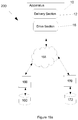
- the control system 200 associated with the apparatus 10 includes components carried by the delivery section 12 and the drive section 16.
- the control system 200 may also interface with or include external computing devices 150 which perform some of the data processing, provide inputs and store outputs from the apparatus 10.
- the apparatus 10 may in some examples be provided to integrally include the functionality of such an external computing devices 150 and in these examples such an external computing device 150 may not be required.
- the computing device 150 may be a mobile computing device, such as a smart phone or tablet, loaded with application software configured to communicate over a network, internet or wireless connection 155 with the apparatus 10.
- the external computing device 150 may include or communicate with an external database 160, and may be configured to perform many or most of the processing steps of the methods disclosed herein.
- the external computing device 150 may carry one or more further processors or memory devices.
- external computing device 150 may also be in the form of a web-server or computer system in communication with a database 160 from which the apparatus 10 may retrieve and store information.
- the computing device 150 or the apparatus 10 may communicate with a server system 170 and server database 172. Such computing devices 150 and server systems 170 are well known and are not described here in any detail.
- the delivery part 12 includes delivery control components 202 including the antenna 70 and the electronic device 75 including the memory device 76 which are communicated with the parts of the control system 200 carried by the drive section 16 in the coupled condition.
- the drive section 16 includes drive control components 204 that may be arranged in a of variety configurations on PCB boards within the drive section 16.
- the drive control components 204 include the processor 78 configured to read the memory device 76, the communication WiFi module 91, the USB data device 42, the battery 32, the trigger read switch 86, the vibration motor 82, an audible buzzer 83, an RFID antenna circuit 85 in electrical communication in the coupled condition with the antenna 70, a position senor 106 which communicates with the processor 78, the display 38 and the indicator lights 40.
- the drive control components 204 include as identified by 206 some components that are different between the first and second examples of the apparatus 10.
- the pressure sensor 44 for example, is replaced with a motor current sensor 934 in the second example, and the pneumatic valves 114, 116 are replaced respectively by the voltage regulator 930 and the current regulator 932 in the second example of the apparatus 10.
- the first and/or second examples may also be fitted with the zero position switch 935 and the maximum position switch 936.
- the reed switch trigger 86, the battery 32 and the inlet pneumatic control valve 114 and the outlet pneumatic control valve 116 are each in electrical communication with the processor 78.
- the processor 78 may be in the form of a microcontroller and include multiple processing units and associated memory to store software code executable by the processor 78 to operate the apparatus 10 in accordance with methods of operation and use as are described below.
- a user typically firstly couples the delivery section 12 to the hand held drive section 16 to form the apparatus 10.
- the apparatus 10 is then configured to undertake a number of initialisation or validation steps including prompting of a user to select a medication type, using the external device 150 or an input such as the screen 38 of the apparatus 10, and reading a medication type data from the memory device 76 associated with the delivery section 12.
- initialisation or validation steps include checking the compatibility and suitability of the delivery section 12 for the hand held drive section 16 as is further detailed below.
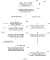
- the method is performed by the system 200 configured by software and includes, at step 302 the system 200 receiving delivery data carried by the electronic or identifier device 75, more specifically the memory device 76, of the delivery section 12.
- the delivery data may include identifier data to identify the particular delivery section 12, operational or configuration data associated with the particular delivery section 12, medication configuration data that may include a medication configuration identifier and if the particular delivery section 12 has already been medication configured, and may also include a medication code of a previously utilised medication used with the delivery section 12.
- the system 200 determines if the delivery section 12 is in a medication-configured state or a non-medication configured state.
- the system 200 preferably the processor 78 of the drive section 16, is configured to determine if the delivery data includes an affirmative or negative medication configuration identifier.
- the medication configuration identifier may simply be a "0" or "1" readable from the memory device 76.
- the system 200 if the delivery section 12 is in a non-medication configured state, then the system 200, preferably via the external computing device 150, carries out a medication configuration routine including, at step 306 prompting and receiving a selected medication from a user to provide medication type selection data.
- the system 200 retrieves medication data (such as medication type, does rates etc) from the database 165 and retrieves further delivery data from delivery section 12 or database 165 such as delivery section type, delivery section medication type data and operational parameters of the delivery section 12.
- medication data such as medication type, does rates etc
- the system 200 determines if the selected medication type is suitable for the delivery section 12. This may include the system 200 comparing the selected medication type data to the delivery section medication type data to determine the medication compatibly and therefore determining one of a compatible state and an incompatible state. In the incompatible state, at step 311, the system 200 may provide an error message or return to prompt the user to reselect the medication type. This, in effect, at least partially disables or restricts the system 200, specifically the apparatus 10, from operation and in the incompatible state the apparatus 10 cannot be used to medicate an animal (i.e. the trigger may be disabled or the like).
- the system 200 writes a medication configuration identifier to the delivery section 12. More specifically, this may include writing to the memory device 76 to include medication data including the medication configuration identifier and a medication code or the like.
- the writing to the memory device 76 that preferably is EEPROM, includes locking the memory device 76 to prevent the memory device 76 from being re-written to different or new medication type. Accordingly, the medication configuration "locks" the delivery section 12 to a particular medication.
- the system 200 is configured to display data, such as text or images via the external computing device 150 or via the display 38 of the apparatus 10, indicating the apparatus 10 is operational and configured, and the selected or configured medication type.
- the apparatus 10 and system 200 may then used to deliver mediation to an animal as is described below with reference to Figure 22 .
- the system 200 receives a configured medication code or data from the delivery data, and at step 316 the system 200 retrieves medication data and further delivery section data. Accordingly, the system 200 loads the pre-configured medication settings and is, in effect, locked to these particular medication type settings for the particular identified connected delivery section 12. The system 200 then proceeds to step 318 so as to be operational and display or indicate, in this instance, the pre-configured medication type data. The apparatus 10 and system 200 may then be used to deliver medication to an animal as is described below with reference to Figure 22 .
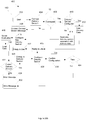
- FIG. 20b there is shown another method 400 for the configuration and compatibility determination of the delivery section 12 coupled to the drive section 16 to form the apparatus 10.
- This method illustrates which parts of the method are preferably, but not necessary essentially, executed by the apparatus 10 of the system 200 and the external computing device 150 of the system 200.
- the method is performed by the system 200 configured by software and includes, at step 402 communicating a user interface and input device with the apparatus 10.
- the user interface and input device may be an associated external computing device 150, which may be a mobile device operating application software.
- the communication may occur via the WiFi module 80 to allow data communication between the input device 150 and the processor 78 of the apparatus 10.
- the display 38 of the apparatus 10 may be a touch screen adapted to interface with and receive user input and, in this case, the apparatus 10 carries or includes the user interface and input device.
- the mobile device operating application software may, in some examples, inturn communicate with the server system 170 that may operate as an application or cloud server and the database 172 may be accessed to store and retrieve data.
- the delivery section 12 is coupled to the drive section 14 and at step 406, the control system 200 is configured to determine if the delivery section 12 is connected to the drive section 18. This may include, for example, attempting to read the memory device 76 or simply determining a positive electrical connection of the electrical connectors 54, 56.
- the user may be prompted, such as by an indicator or message on the display 38 to connect to the delivery section 12.
- the processor 78 identifies that a delivery section 12 is not connected (or may be incorrectly connected) then an error message is sent, at step 408, to the user interface and input device, which in this example, is the external computing device 150. The user may then fit or re-fit the delivery section 12.
- the system 200 determines if the delivery section 12 is new and in a non-configured state, or if the delivery section 12 has been previously configured and is in a medication configured state.
- the processor 78 reads delivery data from the memory device 76.
- the delivery data includes identifier data to identify the particular delivery section 12, configuration data associated with the particular delivery section 12 and medication data which may include a medication code of a previously utilised medication used with the delivery section 12. This step is particularly important because the delivery section 12 is interchangeable and reusable, and the drive section 16, in particular, the processor 78 needs to read the delivery data in order to identify and correctly operate the delivery section 12.
- the delivery data will typically include medication data that may include a medication code of a previously utilised medication used with the delivery section 12.
- the system 200 loads the delivery data that then configures the drive section 16 and system 200 for use with the particular attached delivery section 12.
- the system 200 may also send delivery data to the external computing device 150 such as sending the medication data, history data and other parameters of the particular attached delivery section 12.
- the system 200 may indicate to the user that the system 200 is ready for use. This may be displayed or indicated at the apparatus 10 and/or at the external computing device 150.
- the system 200 then undertakes a medication configuration routine including, at step 414 communicating delivery data including delivery section configuration data to the external computing device 150, and at step 416 the external computing device 150 initiates a local routine to guide the user through configuring the particular delivery section 12 to a particular medication.
- the user selects a medication type using the input device provided by the external computing device 150.
- the medication type may be entered as a code or the user may select the medication type from a predefined list.
- selected medication or substance type data is loaded by the system 200 via the computing device 150 either from local memory or from an external database accessible 172 via the server system 170.
- the selected medication type data includes a code for the medication type and medication values and information such as dose rates (mm/kG).
- the system 200 then undertakes a compatibility check to determine if the correct type of delivery section 12 is connected for the selected medication.
- the delivery data may include delivery section type data indicating if the delivery section 12 is suitable for one of injecting, drenching or back lining, and delivery medication type data that may include data indicating the types of medication that are suitable for the particular delivery section.
- the delivery section type data and/or delivery medication type data may also be loaded from an external database 160 or 172 once the delivery section 12 is identified by the system 200.
- the system 200 then conducts comparative operations, via the computer device 150, to determine if the delivery type medication data and selected medication type data are compatible and/or if the delivery section type and the selected medication type data both indicate the same or a compatible delivery section type being, for example, one of injecting, drenching or back lining. If the type of delivery section 12 is not compatible with the selected medication, then the method moves to step 424 in which indications are provided to the user, for example via the display or computer device 150, that the incorrect delivery part 12 is fitted.
- the system 200 is also configured enter at least partially inoperative state in which the apparatus 10 is unable to deliver medication.
- the system 200 configures the delivery section 12 to the particular selected medication. This includes the computer device 150 of the system 200 communicating new delivery data including medication type data to the particular delivery section 12.
- the system 200 via the processor 78, is then configured to write specific configuration and medication data to the memory device 76 carried by the particular delivery section 12 and locks the specific configuration data to the memory device 76 which is preferably EEProm memory.
- the specific configuration data includes the selected medication type data or data to represents the selected medication type data so that when the memory device 76 is again read at a later stage the processor 78 is able to determine the medication history of the particular delivery section 12. Accordingly, once a particular delivery section 12 is utilised with a particular selected medication, the particular delivery section 12 is, in essence, hard coded to always be only usable with the particular selected medication. This assists with inhibiting medication cross-contamination.
- the processor 78 then undertakes a further medication compatibility check to determine if the connected delivery section 12 is suitable for the selected medication type.
- the processor 78 receives delivery data from the now locked memory device 76, in particular data representing or used to determine, delivery medication type data which indicates the particular medication type associated with the connected delivery section 12.
- the processor 78 also receives, the selected medication type data representing the selected medication type selected for use.
- the processor 78 then conducts processing operations to determine compatibility of the delivery medication type and the selected medication type to provide compatibility data representing at least one of a compatible medication state and an incompatible medication state.
- the processor 78 enables the apparatus 10 to a ready to medicate condition, at step 415, in which the user may operate the apparatus 10 in accordance with the method 600 for delivering a substance to an animal as is further described below.
- the processor 78 may be configured to send a ready signal to the display 38 or to the indicator lights 40.
- the system 200 is configured to at least partially disable operation of the medication delivery apparatus 10 so as to inhibit delivery of medication.
- the processor 78 may be configured to send an error signal to the computing device 150, to the display 38 or to the indicator lights 40. In the incompatible or error medication state, the particular delivery section 12 may need to be removed and interchanged at step 432.
- the method including, at step 502 an input device such as an external computing device 150, which may be a mobile device, being launched and communicated with the apparatus 10 at step 504.
- the communication may occur via the WiFi module 80 to allow data communication between the input device 150 and the processor 78 of the apparatus 10.
- the display 38 may be a touch screen and, in this case, the apparatus 10 carries the input device.
- a user selects a medication type using the input device.
- the medication type may be entered as a code or the user may select the medication type from a predefined list.
- a medication specification type data is loaded by the processor 78 either from local memory carried by the apparatus 10 or from an external source such as an external mobile device or an external database accessible via a webserver.
- the selected medication type data includes a code for the medication type and information such as dose rates (mm/kG).
- the processor 78 is configured, by software, to determine if the delivery section 12 is connected to the drive section 18. This may include, for example, attempting to read the memory device 76 or simply determining a positive electrical connection of the electrical connectors 54, 56. If no delivery section 12 is connected, at step 312, the use may be prompted, such as by an indicator or message on the display 38 to connect to the delivery section 12.
- the processor 78 is configured to read delivery data from the memory device 76.
- the delivery data includes identifier data to identify the particular delivery section 12, configuration data associated with the particular delivery section 12 and medication data which may include a medication code of a previously utilised medication used with the delivery section 12. This step is particularly important because the delivery section 12 is interchangeable and the driver section 16, in particular, the processor 78 needs to read the delivery data in order to identify and correctly operate the delivery section 12.
- the configuration data may include variables such as volume of the delivery cylinder 81, volumetric rates such as mL of substance discharged for mm of linear movement of the substance plunger 80. Other variables may include the total stroke length.
- the identifier data may include data to indicate the type of delivery section 12 which may be for example delivery sections 12 for injecting, drenching or back-lining.
- the processor 78 then undertakes an initial compatibility check to determine if the correct type of delivery section 12 is connected for the selected medication.
- the delivery data may include data that the delivery section 12 is suitable for one of injecting, drenching or back lining and selected medication type data may include data indicating the medication is suitable for one of injecting, drenching or back lining.
- the processor 78 then conducts comparative operations to determine if the delivery data and the selective medication type data both indicated the same delivery type being one of injecting, drenching or back lining. If the type of delivery section 12 is not compatible with the selected medication, then the method moves to steps 528 and 530 in which indications are provided to the user, for example via the display, that the incorrect delivery part 12 is fitted.
- the processor 78 is also configured an at least partially inoperative state in which the apparatus 10 is unable to deliver medication.
- the processor 78 then undertakes a further identification step in which the processor 78 determined if the delivery section 12 has been previously utilised and configured.
- the processor 78 retrieves or processes retrieved delivery data including the identification data from the memory device 76 carried by the particular delivery section 12.
- the identification data may include prior use data which indicates if the particular delivery section 12 has been previously configured or used.
- the processor 78 then writes specific configuration data to the memory device 76 carried by the particular delivery section 12 and locks the specific configuration data on to the memory device 76 which is preferably EEProm memory.
- the specific configuration data includes the selected medication type data or data to represents the selected medication type data so that when the memory device 76 is again read at a later stage the processor 78 is able to determine the medication history of the particular delivery section 12. Accordingly, once a particular delivery section 12 is utilised with a particular selected medication, the particular delivery section 12 is, in essence, hard coded to always be only usable with the particular selected medication. This assist with inhibiting medication cross-contamination.
- the processor 78 then undertakes a secondary medication compatibility check to determine if the connected delivery section 12 is suitable for the selected medication type.
- the processor 78 receives delivery data from the now locked memory device 76, in particular data representing or used to determine, delivery medication type data which indicates the particular medication type associated with the connected delivery section 12.
- the processor 78 also receives, the selected medication type data representing the selected medication type selected for use.
- the processor 78 then conducts processing operations to determine compatibility of the delivery medication type and the selected medication type to provide compatibility data representing at least one of a compatible medication state and an incompatible medication state.
- the processor 78 enables the apparatus 10 to a ready to medicate condition in which the user may operate the apparatus 10 in accordance with the method 600 for delivering a substance to an animal as is further described below.
- the processor 78 may be configured to send a ready signal to the display 38 or to the indicator lights 40.
- the processing system 78 is configured to at least partially disable operation of the medication delivery apparatus 10 so as to inhibit delivery of medication.
- the processor 78 may be configured to send an error signal to the display 38 or to the indicator lights 40.
- the particular delivery section 12 may need to be removed and interchanged at step 530.
- the routine then proceeds to step 512 where a new delivery section 12 is connected to the drive section 12.
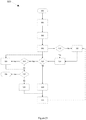
- a method 600 for delivering a substance to an animal and the associated operation of the apparatus 10 is further described.
- the delivery section 12 is connected to the drive section 16 and is in the operative compatible medication state as described above with reference to methods 300 and 400.
- a particular animal is selected for medication and at step 604, if the animal includes an identification means such as an animal RFID tag, an animal identification step is undertaken at step 606 in which the animal RFID tag is scanned or read by the RFID reader 70 of the apparatus 10.
- the RFID reader may be activated by user actuation of the trigger and the animal identification data may be received by and processed by the processor 78.
- the system 200 is configured to determine if a fixed dose or a calculated dose is to be administered. If the animal does not include an identification means or if the animal is not identifiable the system 200, preferably the processor 78, determines that a fixed or pre-determined dose should be applied to the animal. This pre-determined dose or dose rate may be included in the selected medication type data as was described above in relation to methods 300 or 400. The fixed dose may be inputted by a user or predetermined by the system 200.
- the control system 200 then initiates an animal identification lookup step, at step 610, wherein the identification of the animal is matched to a pre-defined database or stored animal information located in the memory of the control system 200 or an externally accessible device or database such as database 160.
- This stored information may be pre-loaded or stored in the memory and may include animal parameters such as weight, height, age, sex and/or other similar information.
- the animal parameters may include the animal weight, type and age as well as related information which is used to calculate the dose rate.
- the dose may be manually inputted by the user or may be a fixed dose.
- the dose rate is calculated at a dose rate calculation or processing step using animal parameters and medication parameters.
- the medication parameters may include information such as type of medication and dose rate lookup tables, for example dose in ml/kg for selected medications, which are utilised in the dose rate calculation.
- the medication parameters may be pre-loaded or stored in the memory and accessed by the processor.
- the dose rate calculation includes determining how far to linearly move to shaft 104 and hence the plunger 80 to deliver the dose, or pre-determined quantity, of the medication to the animal.
- the system 200 receives delivery section data that includes volume parameters such as mL/mm. So, for example, if the determined dose is 5mL, and the volume parameter, V, of the delivery section 12 is, 1mL/mm, the system 200 is configured to determine a linear movement parameter, L, that in this case would 5mm (i.e 5mm linear plunger movement is required to expel 5mL to substance to the animal).
- the linear position sensor 106 continuously monitors or measures this linear distance to provide position feedback for the control system 200.
- the trigger 34 is actuated to activate the apparatus 10, via the control system 200, to begin delivery of the medication through the application delivery part or tip 22.
- the process for medication flow into and out of the apparatus 10 may function as follows.
- the apparatus 10 has undergone an initial priming step whereby air is evacuated from the medication reservoir 77 and the medication reservoir 77 is filled with the substance.
- the pneumatic control valve 114 when trigger 34 is activated or pulled the pneumatic control valve 114 is moved to a fill position allowing a pressurised gas, for example, gas from the pressure canister 31, into the drive cylinder 100 to pressurise and urge plunger 98 forward from a first position toward a second position which, in the coupled condition, in turn moves the delivery plunger 80 and hence the medication reservoir 77 toward the contracted state.
- the fluid pressure inside the medication reservoir 77 thereby opening the valve 94 and maintaining the valve 92 in the ordinarily closed position.
- the drive arrangement 18 is electrically powered and the electric drive arrangement 900 including the electric motor 902 is activated by the control system 200 to move the plunger 80 in the same manner as described above.
- the measurement or linear position sensor 106 is measuring the distance moved by the rod 104 and hence movement of the delivery plunger 80 coupled thereto.
- the distance measurement is converted by the control system 200, to a volume of substance administered or a dose.
- the measurement data provided to the processor 78 allows for feedback control of the delivery plunger 80 and medication delivery therefrom.
- the exhaust pneumatic control valve 116 is moved to an open or re-fill position in which an evacuation or exhaust port is opened between the drive cylinder 100 and the external environment. This allows the return spring 103 to move the drive plunger 98 back to the first position in which the medication reservoir 77 is again in the expanded state.
- the medication inlet valve 92 moves to an open position which allows the flow of the substance into the medication reservoir 77 via the conduit 88.
- the valve 94 moves to a closed position to prevent air entering the medication reservoir 77 and maintains the vacuum.
- the drive plunger 80 then reaches its mechanical limits and is retained in the first position until the trigger 34 is next actuated.
- the couplings 50, 52 between the drive plunger 98 and delivery plunger 80 result in the delivery plunger 80 being actuated in a likewise motion and being controlled by the movement of the drive plunger 98.
- the drive arrangement 18 is electrically powered and the electric drive arrangement 900 including the electric motor 902 is activated by the control system 200 to move the plunger 98 in the same manner as described above.
- the micro-chain 908 moves the shaft 104 and hence the drive plunger 80 in both the forward and reverse directions and therefore a return spring 103 is not required in the second example.
- dose data representing the measured delivered dose is written internal memory 84 carried by the drive section 12, and at step 620 the dose data is written to memory of the external computing device 150, such as a mobile device.
- the apparatus 10 then enters a ready or stand-by mode awaiting the next actuation of the trigger 34.
- the dose data is also written to the server system 170 and the database 172 thereby enabling synchronising of the dose data between the apparatus 10, external computing device 150 and server system 170.
- the recorded dose data may include or be associated with the following animal identification data, mediation type data, dose amount, batch number, user ID, farm ID, date, time, apparatus serial number including delivery section serial number and application software version.
- an apparatus having a split arrangement with a removable and interchangeable delivery section and a main drive section which operates and controls the delivery section.
- the delivery section may be considered an adaptor or interchangeable head which includes a medication reservoir and plunger which when coupled to the main drive section is actuated and controlled by the main drive section.
- the delivery section having the medication reservoir fully separates any medication carried by or associated with the delivery section from the main drive section.
- the interchangeable delivery section also allows different types of the delivery section to be coupled with a common main drive section providing the apparatus with a high level of flexibility.
- the delivery section carries an identifier or memory device that uniquely identifies the delivery section such as providing a code or other data to identify the delivery section to the control system.
- This identifier allows the delivery section to be associated with a particular medication type, such as a previously used medication, and may be associated with operational parameters of the delivery section to enable the main drive section to correctly operate the delivery section.
- the memory device may also be preferably hard coded on the first use of the delivery section with a particular medication type such that delivery section is, in-effect, locked to be only used with that particular medication type.
- the apparatus in conjunction with the control system is able to determine if the delivery section has been previously used and configured to a particular type of medication, and if in a configured state, restrict the delivery section to being used with the particular configured medication. However, if the delivery section is new and in a non-configured state, the system able to receive a user selected medication, check that the connected delivery section is compatible with the user selected medication, and then configure the delivery section for use with the user selected medication. The system then is able to "lock" the memory device to the configured medication and thereby the delivery section being in the configured state.
- the memory device of the delivery section may include the operational parameters and these may be stored to the memory device for reading by the processor carried by the delivery section to enable the main drive section to correctly operate the delivery section. Accordingly, when the main drive section is configured to deliver a particular medication type, the control system is able to check that the attached delivery section is medication compliant or compatible, and also have access to operational parameters for operation of the delivery section. This provides highly advantageous medication compliance functionality.
Claims (15)
- Appareil portatif (10) destiné à l'administration d'une substance à un animal, l'appareil comprenant :une section d'administration (12) comprenant un système d'administration (14) conçu pour administrer la substance à l'animal ; etune section d'entraînement (16) comprenant un système d'entraînement (18) conçu pour actionner le système d'administration dans une condition accouplée dans laquelle la section d'administration est accouplée à la section d'entraînement ;dans lequel la section d'administration comprend un dispositif électronique (75) conçu pour communiquer avec un système de commande (200) associé à au moins la section d'entraînement dans la condition accouplée; caractérisée en ce que :
la section d'administration est indifféremment amovible et le dispositif électronique est configurable de manière à être lisible par le système de commande de sorte que le système de commande est en mesure d'identifier et de faire fonctionner la section d'administration amovible. - Appareil portatif selon la revendication 1, dans lequel le dispositif électronique est configurable pour mémoriser au moins l'une des informations de configuration et des informations sur le type de la substance.
- Appareil portatif selon la revendication 2, dans lequel le dispositif électronique comprend la mémoire (76) configurable pour mémoriser ladite au moins une des informations de configuration et des informations sur le type de la substance.
- Appareil portatif selon la revendication 3, dans lequel le système de commande comprend un processeur (78) porté par au moins l'une parmi la section d'entraînement et un dispositif informatique externe, le processeur étant configurable pour lire ladite au moins une des informations de configuration et des informations sur le type de la substance ce qui permet d'activer la section d'entraînement, en association avec le système de commande, pour identifier et faire fonctionner la section d'administration.
- Appareil portatif selon la revendication 3, dans lequel le système de commande comprend un processeur porté dans la section d'entraînement, le processeur étant configurable pour lire ladite au moins une des informations de configuration et des informations sur le type de la substance ce qui permet d'activer la section d'entraînement pour identifier et faire fonctionner la section d'administration.
- Appareil portatif selon la revendication 4 ou la revendication 5, dans lequel la section d'administration et la section d'entraînement comprennent des bornes électriques correspondantes agencées pour faire communiquer la mémoire du dispositif électronique avec le processeur porté par la section d'entraînement.
- Appareil portatif selon l'une quelconque des revendications 1 à 6, dans lequel le système d'administration comprend un piston de substance (80) et le système d'entraînement comprend une pièce d'entraînement (96) conçue pour déplacer le piston de substance dans la condition accouplée.
- Appareil portatif selon la revendication 7, dans lequel le système d'administration comprend une pièce d'accouplement d'administration (52) accouplée au piston de substance et le système d'entraînement comprend une pièce d'accouplement d'entraînement (50) accouplée à la pièce d'entraînement, dans lequel la pièce d'accouplement d'administration et la pièce d'accouplement d'entraînement sont agencées de manière à être accouplées de manière détachable dans la condition accouplée de sorte que le mouvement de la pièce d'entraînement cause un mouvement semblable du piston de substance.
- Appareil portatif selon la revendication 8, dans lequel le système d'administration comprend un réservoir de substance (77) et un piston de substance (87) reçu à l'intérieur de la substance et dans lequel le système d'entraînement comprend une pièce d'entraînement (102) conçue pour s'accoupler avec le piston de substance dans la condition accouplée de manière à déplacer le piston de substance ce qui permet de déplacer le réservoir de substance entre un état expansé, dans lequel la substance peut être située à l'intérieur du réservoir de substance et un état contracté dans lequel la substance peut au moins être partiellement expulsée du réservoir de substance.
- Appareil portatif selon la revendication 1, dans lequel le dispositif électronique est conçu pour mémoriser des informations d'administration associées à la section d'administration et le système de commande est configuré pour recevoir et traiter les informations d'administration.
- Appareil portatif selon la revendication 10, dans lequel les informations d'administration comprennent des données indiquant si la section d'administration est dans l'un parmi l'état configuré de la substance et l'état non configuré de la substance et dans lequel le système de commande est configuré pour lire les données et déterminer si la section d'administration est dans l'un parmi l'état configuré de la substance et l'état non configuré de la substance.
- Appareil portatif selon la revendication 11, dans lequel, dans l'état non configuré de la substance, le système de commande est conçu pour recevoir les données de type de la substance sélectionnée et déterminer si les données de type de la substance sélectionnée et la section d'administration sont dans l'un parmi l'état compatible de la substance et l'état non compatible de la substance.
- Appareil portatif selon la revendication 12, dans lequel, dans l'état compatible de la substance, le système de commande est configuré pour écrire les données de type de la substance indicatives de la substance sélectionnée sur le dispositif électronique porté par la section d'administration ce qui permet de configurer la section d'administration à l'état configuré de la substance.
- Appareil portatif selon la revendication 10, dans lequel le système de commande est configuré pour recevoir des données de sélection de type de la substance et dans lequel les informations d'administration comprennent les données de type de la substance d'administration associées à la section d'administration,
dans lequel le système de commande est configuré pour déterminer si les données de sélection de type de la substance et les données de type de la substance d'administration représentent des substances compatibles et restreindre le fonctionnement de l'appareil si les substances sont non compatibles. - Appareil portatif selon la revendication 10, dans lequel le système de commande est configuré pour recevoir des données de sélection de type de la substance et dans lequel les informations d'administration comprennent les données de type de la section d'administration indiquant le type de la section d'administration accouplée,
dans lequel le système de commande est configuré pour déterminer si les données de sélection de type de la substance et les données de type de la section d'administration représentent une combinaison compatible et restreindre le fonctionnement de l'appareil si la combinaison n'est pas compatible.
Applications Claiming Priority (2)
| Application Number | Priority Date | Filing Date | Title |
|---|---|---|---|
| AU2014905258A AU2014905258A0 (en) | 2014-12-23 | Delivery Apparatus, System and Method | |
| PCT/AU2015/050832 WO2016101031A1 (fr) | 2014-12-23 | 2015-12-22 | Appareil d'administration, système et procédés associés |
Publications (3)
| Publication Number | Publication Date |
|---|---|
| EP3236882A1 EP3236882A1 (fr) | 2017-11-01 |
| EP3236882A4 EP3236882A4 (fr) | 2018-08-08 |
| EP3236882B1 true EP3236882B1 (fr) | 2020-02-05 |
Family
ID=56148791
Family Applications (1)
| Application Number | Title | Priority Date | Filing Date |
|---|---|---|---|
| EP15871354.5A Active EP3236882B1 (fr) | 2014-12-23 | 2015-12-22 | Appareil d'administration, système et procédés associés |
Country Status (9)
| Country | Link |
|---|---|
| US (2) | US11883260B2 (fr) |
| EP (1) | EP3236882B1 (fr) |
| KR (1) | KR20170097020A (fr) |
| CN (1) | CN107106280A (fr) |
| AU (1) | AU2015372441A1 (fr) |
| BR (1) | BR112017011213A2 (fr) |
| CA (1) | CA3009221A1 (fr) |
| IL (1) | IL253090A0 (fr) |
| WO (1) | WO2016101031A1 (fr) |
Cited By (1)
| Publication number | Priority date | Publication date | Assignee | Title |
|---|---|---|---|---|
| US11957542B2 (en) | 2020-04-30 | 2024-04-16 | Automed Patent Holdco, Llc | Sensing complete injection for animal injection device |
Families Citing this family (7)
| Publication number | Priority date | Publication date | Assignee | Title |
|---|---|---|---|---|
| BR112019009901A2 (pt) * | 2016-11-17 | 2019-08-13 | Syrinjector Ltd | sistema para vacinação em massa e injetor portátil |
| WO2018107220A1 (fr) * | 2016-12-12 | 2018-06-21 | Automed Pty Ltd | Améliorations apportées à l'administration de médicaments à des animaux |
| US10772715B2 (en) * | 2017-04-25 | 2020-09-15 | Digirodeo S.A. | Injection pistol for animal treatment with identification assistant |
| KR20190029220A (ko) * | 2017-09-12 | 2019-03-20 | 최규동 | 주사 장치용 주사액 카트리지 판별 및 관리 시스템 |
| WO2019235943A1 (fr) | 2018-06-07 | 2019-12-12 | Simcro Limited | Perfectionnements apportés ou se rapportant à des applicateurs |
| GB2612593A (en) * | 2021-11-03 | 2023-05-10 | Owen Mumford Ltd | Syringe identification |
| WO2024046932A1 (fr) * | 2022-08-30 | 2024-03-07 | Sanofi | Dispositif complémentaire pour dispositif d'injection |
Family Cites Families (375)
| Publication number | Priority date | Publication date | Assignee | Title |
|---|---|---|---|---|
| US2778359A (en) * | 1954-04-09 | 1957-01-22 | Friedman Benjamin | Hypodermic syringe device |
| US3941130A (en) | 1975-03-18 | 1976-03-02 | Tibbs Robert C | Sequential trigger release for injection device |
| US4073321A (en) | 1976-03-15 | 1978-02-14 | George Moskowitz | Adjustable blocking means for dosage regulation |
| US4106770A (en) | 1976-09-01 | 1978-08-15 | Gray John M | Hypodermic syringe projectile |
| US4103684A (en) | 1976-12-30 | 1978-08-01 | Aaron Ismach | Hydraulically powered hypodermic injector with adapters for reducing and increasing fluid injection force |
| US4261358A (en) | 1979-10-01 | 1981-04-14 | Walter Vargas | Automatic syringe plunger |
| US4275729A (en) | 1979-10-29 | 1981-06-30 | Jules Silver | Adjustable dosage syringe |
| US4316463A (en) | 1981-01-26 | 1982-02-23 | Vac-O-Cast, Inc. | Corrosive protected hypodermic module |
| GB2109690B (en) | 1981-02-12 | 1985-02-20 | Robert Charles Turner | Dose metering plunger devices for use with syringes |
| US4435173A (en) * | 1982-03-05 | 1984-03-06 | Delta Medical Industries | Variable rate syringe pump for insulin delivery |
| US4475905A (en) | 1982-09-30 | 1984-10-09 | Himmelstrup Anders B | Injection device |
| US4547189A (en) | 1984-03-05 | 1985-10-15 | John A. Long | Insulin syringe injector apparatus with auto-aspirator feature |
| DE3417757C2 (de) | 1984-05-12 | 1994-11-10 | Lucas Dieter Dr | Injektionsspritze |
| BR8404286A (pt) | 1984-08-28 | 1986-04-08 | Sergio Landau | Seringa hipodermica a pressao |
| US4664653A (en) | 1986-02-24 | 1987-05-12 | Sagstetter William E | Manually operated reusable injection apparatus |
| US4710162A (en) | 1986-10-31 | 1987-12-01 | Johnson Gerald W | Fat collection and injection process into same body |
| DE3709783C1 (de) | 1987-03-25 | 1988-04-14 | Blendax Werke Schneider Co | Dosierspritze |
| US4735611A (en) | 1987-03-30 | 1988-04-05 | Midwest Sport Distributors, Inc. | Projectile syringe for blowpipe |
| US6056716A (en) | 1987-06-08 | 2000-05-02 | D'antonio Consultants International Inc. | Hypodermic fluid dispenser |
| GB8713810D0 (en) | 1987-06-12 | 1987-07-15 | Hypoguard Uk Ltd | Measured dose dispensing device |
| US5011476A (en) | 1987-07-01 | 1991-04-30 | Foster Robert J C | Single fill and use syringe |
| US4858607A (en) | 1987-10-16 | 1989-08-22 | Pavel Jordan & Associates | Plastic device for injection and obtaining blood samples |
| US5026349A (en) | 1988-10-05 | 1991-06-25 | Autoject Systems Inc. | Liquid medicament injector system |
| US4902279A (en) | 1988-10-05 | 1990-02-20 | Autoject Systems Inc. | Liquid medicament safety injector |
| US4955868A (en) | 1988-11-28 | 1990-09-11 | Edward Klein | Disposable safety medical syringe |
| US4988339A (en) | 1988-12-30 | 1991-01-29 | Vadher Dinesh L | Retractable needle/syringe devices for blood collection, catheterization, and medicinal injection procedures |
| GB8900763D0 (en) | 1989-01-13 | 1989-03-08 | Kabi Vitrum Peptide Hormones A | Multi-dose syringe |
| US5127906A (en) | 1989-04-28 | 1992-07-07 | Flp Enterprises, Inc. | Non-reusable syringe |
| US6096005A (en) | 1989-07-11 | 2000-08-01 | Mdc Investment Holdings, Inc. | Retractable needle medical devices |
| US5407431A (en) | 1989-07-11 | 1995-04-18 | Med-Design Inc. | Intravenous catheter insertion device with retractable needle |
| US4994034A (en) | 1989-07-11 | 1991-02-19 | Botich Michael J | Retractable needle hypodermic syringe system |
| US5163908A (en) | 1989-10-16 | 1992-11-17 | Lambert William S | Fail safe composite hypodermic syringe with reversible needle and guard assembly |
| GB9007113D0 (en) | 1990-03-29 | 1990-05-30 | Sams Bernard | Dispensing device |
| US5226896A (en) | 1990-04-04 | 1993-07-13 | Eli Lilly And Company | Dose indicating injection pen |
| US5078683A (en) * | 1990-05-04 | 1992-01-07 | Block Medical, Inc. | Programmable infusion system |
| US5271744A (en) | 1991-04-29 | 1993-12-21 | George C. Kramer | System and method for rapid vascular drug delivery |
| US5176643A (en) | 1991-04-29 | 1993-01-05 | George C. Kramer | System and method for rapid vascular drug delivery |
| US5451210A (en) | 1991-04-29 | 1995-09-19 | Lifequest Medical, Inc. | System and method for rapid vascular drug delivery |
| DK134691D0 (da) | 1991-07-12 | 1991-07-12 | Novo Nordisk As | Apparat |
| US5151088A (en) | 1991-07-31 | 1992-09-29 | The Board Of Trustees Of The Leland Stanford Junior University | Safety needle and syringe assembly |
| DK175491D0 (da) | 1991-10-18 | 1991-10-18 | Novo Nordisk As | Apparat |
| DK194291D0 (da) | 1991-11-29 | 1991-11-29 | Novo Nordisk As | Sproejte til automatisk injektion. |
| US5613952A (en) | 1991-12-23 | 1997-03-25 | Syringe Develpoment Partners | Safety syringe |
| DE4205036C1 (en) | 1992-02-19 | 1993-06-17 | Henke-Sass, Wolf Gmbh, 7200 Tuttlingen, De | Injection cylinder for subcutaneous vaccination - comprises first hollow cylindrical tube in which is fitted telescopically second tube with reduced dia. |
| US5322511A (en) | 1992-04-21 | 1994-06-21 | Sterling Winthrop Inc. | Portable hand-held power injector |
| US5201720A (en) | 1992-04-21 | 1993-04-13 | Joseph Borgia | Syringe holding and ejecting assembly |
| US5300041A (en) | 1992-06-01 | 1994-04-05 | Habley Medical Technology Corporation | Dose setting and repeating syringe |
| GB9212742D0 (en) | 1992-06-16 | 1992-07-29 | Sterimatic Holdings Ltd | Syringe or blood collection system |
| US5267963A (en) | 1992-08-21 | 1993-12-07 | Nicholas Bachynsky | Medication injection device |
| US5190526A (en) | 1992-09-18 | 1993-03-02 | Murray Kenneth W | Hypodermic safety syringe with retracting needle system |
| US5391157A (en) | 1992-10-20 | 1995-02-21 | Eli Lilly And Company | End of dose indicator |
| US5545147A (en) | 1992-10-20 | 1996-08-13 | Eli Lilly And Company | Anti-backup improvement for hypodermic syringes |
| US6068615A (en) | 1994-07-22 | 2000-05-30 | Health Hero Network, Inc. | Inductance-based dose measurement in syringes |
| US5411487A (en) | 1992-12-07 | 1995-05-02 | Castagna; John F. | Hypodermic syringe with automatic needle cover |
| US5320609A (en) | 1992-12-07 | 1994-06-14 | Habley Medical Technology Corporation | Automatic pharmaceutical dispensing syringe |
| US5346480A (en) | 1992-12-14 | 1994-09-13 | Q-Med, Inc. | Syringe with retractable needle |
| US5298024A (en) | 1992-12-28 | 1994-03-29 | Frank Richmond | Multi-liquid medicament delivery system with reflex valves |
| DE69427226T2 (de) | 1993-03-24 | 2001-08-30 | Owen Mumford Ltd | Vorrichtung zur injektion |
| US5695472A (en) | 1993-05-27 | 1997-12-09 | Washington Biotech Corporation | Modular automatic or manual emergency medicine injection system |
| US5833669A (en) | 1993-05-27 | 1998-11-10 | Washington Biotech Corp. | Medicine injection syringe constructions |
| US5358489A (en) | 1993-05-27 | 1994-10-25 | Washington Biotech Corporation | Reloadable automatic or manual emergency injection system |
| US5620421A (en) | 1993-12-09 | 1997-04-15 | Schmitz; William L. | Syringe injector system |
| FR2715071B1 (fr) | 1994-01-17 | 1996-03-01 | Aguettant Lab | Injecteur automatique de médicament. |
| US5514097A (en) | 1994-02-14 | 1996-05-07 | Genentech, Inc. | Self administered injection pen apparatus and method |
| US5792117A (en) | 1994-07-22 | 1998-08-11 | Raya Systems, Inc. | Apparatus for optically determining and electronically recording injection doses in syringes |
| AU3707695A (en) | 1994-09-27 | 1996-04-19 | Societe De Conseils De Recherches Et D'applications Scientifiques (S.C.R.A.S.) | Safety injection device |
| US5560317A (en) | 1994-10-19 | 1996-10-01 | N J Phillips Pty Limited | Mechanism to dispense medication to animals |
| FR2736553B1 (fr) | 1995-07-12 | 1998-01-09 | Soc Et Et D Applic Tech Sedat | Seringue d'injection, notamment de produits medicaux liquides, a protecteur d'aiguille mobile |
| US5722956A (en) | 1995-08-24 | 1998-03-03 | The General Hospital Corporation | Multi-dose syringe driver |
| US5562626A (en) | 1995-09-11 | 1996-10-08 | Sanpietro; Joseph A. | Safety syringe |
| ATE221396T1 (de) | 1996-04-02 | 2002-08-15 | Disetronic Licensing Ag | Injektionsgerät |
| ES2183939T3 (es) | 1996-04-02 | 2003-04-01 | Disetronic Licensing Ag | Aparato de inyeccion. |
| IT1284642B1 (it) | 1996-05-02 | 1998-05-21 | Ermanno Greco | Perfezionamenti alle siringhe automatiche per iniezione |
| GB9612724D0 (en) | 1996-06-18 | 1996-08-21 | Owen Mumford Ltd | Improvements relating to injection devices |
| US5713871A (en) | 1996-08-16 | 1998-02-03 | Stock; David M. | Protective sleeve for hypodermic needle |
| US5919166A (en) | 1996-09-13 | 1999-07-06 | Mcgary; R. Kern | Non-reusable retractable safety syringe |
| US5769822A (en) | 1996-09-13 | 1998-06-23 | Mcgary; R. Kern | Non-reusable retractable safety syringe |
| US5776107A (en) | 1996-12-31 | 1998-07-07 | Delab | Injection device |
| US6203530B1 (en) | 1997-01-28 | 2001-03-20 | Pos-T-Vac, Inc. | Auto-injection device |
| DE69819352T2 (de) | 1997-02-12 | 2004-08-19 | Nardino Righi | Einwegsicherheitsspritze |
| US5882342A (en) | 1997-04-11 | 1999-03-16 | Safety Medical Manufacturing, Inc | Safety medical syringe with retractable needle |
| US5911703A (en) | 1997-05-22 | 1999-06-15 | Avant Drug Delivery Systems, Inc. | Two-stage fluid medicament jet injector |
| GB9716065D0 (en) | 1997-07-31 | 1997-10-01 | Owen Mumford Ltd | Improvements relating to injection devices |
| CA2300930C (fr) | 1997-08-21 | 2007-10-16 | Owen Mumford Limited | Ameliorations apportees aux dispositifs d'injection |
| AUPO940697A0 (en) | 1997-09-23 | 1997-10-16 | Kaal, Joseph Hermes | Retractable syringe |
| IE970782A1 (en) | 1997-10-22 | 1999-05-05 | Elan Corp | An improved automatic syringe |
| US6461333B1 (en) | 1997-10-30 | 2002-10-08 | Laboratoire Aquettant | Safety syringe for medical use |
| US6015438A (en) | 1997-11-14 | 2000-01-18 | Retractable Technologies Inc. | Full displacement retractable syringe |
| EP1032444B1 (fr) | 1997-11-17 | 2004-05-19 | Tecpharma Licensing AG | Dispositif pour faire penetrer une aiguille |
| NZ332852A (en) | 1997-11-19 | 2000-10-27 | Eidson Associates Inc | Veterinary medicament delivery system in the form of a gun |
| US6482176B1 (en) | 1997-11-27 | 2002-11-19 | Disetronic Licensing Ag | Method and device for controlling the introduction depth of an injection needle |
| US6610042B2 (en) | 1997-12-05 | 2003-08-26 | Felton Medical, Inc. | Disposable unit-dose jet-injection syringe for pre-filled and/or transfilled liquid injectable medical drug or vaccine products and method thereof |
| US5997500A (en) | 1998-04-20 | 1999-12-07 | Ivy Animal Health, Inc. | Pneumatically operated veterinary pellet implanter |
| FR2782011B1 (fr) | 1998-08-07 | 2000-11-03 | Sedat | Seringue d'injection a protecteur d'aiguille mobile exterieurement |
| US6428528B2 (en) | 1998-08-11 | 2002-08-06 | Antares Pharma, Inc. | Needle assisted jet injector |
| GB9817662D0 (en) | 1998-08-13 | 1998-10-07 | Crocker Peter J | Substance delivery |
| SE9803662D0 (sv) | 1998-10-26 | 1998-10-26 | Pharmacia & Upjohn Ab | Autoinjector |
| US6312412B1 (en) | 1998-12-02 | 2001-11-06 | V. C. Saied, M.D. | Apparatus and method for painless intramuscular or subcutaneous injections |
| DE19856167C1 (de) | 1998-12-05 | 2000-05-04 | Vetter & Co Apotheker | Nadelschutzanordnung für Spritzen, Karpulen und dergleichen Injektionsinstrumente |
| GB9903475D0 (en) | 1999-02-17 | 1999-04-07 | Owen Mumford Ltd | Improvements relating to injection devices |
| DE29904864U1 (de) | 1999-03-17 | 2000-08-03 | Braun Melsungen Ag | Injektionsvorrichtung mit einem Pen |
| SE9901736D0 (sv) | 1999-05-12 | 1999-05-12 | Pharmacia & Upjohn Ab | Injectino device and method for ITS operation |
| US20020004652A1 (en) | 1999-06-18 | 2002-01-10 | Asbaghi Hooman A. | Protective device for a fillable injection syringe |
| DE29912965U1 (de) | 1999-07-24 | 1999-09-16 | Hoelzle Dieter Tech Projekte | Injektionsvorrichtung |
| ATE282451T1 (de) | 1999-09-07 | 2004-12-15 | Controlled Syringe Inc Comp | Zurückziehbare nadelanordnung |
| US6102896A (en) | 1999-09-08 | 2000-08-15 | Cambridge Biostability Limited | Disposable injector device |
| TW453884B (en) | 1999-09-16 | 2001-09-11 | Novo Nordisk As | Dose setting limiter |
| US6171285B1 (en) | 1999-10-06 | 2001-01-09 | R. Steven Johnson | Retractable syringe |
| US6514230B1 (en) | 1999-10-12 | 2003-02-04 | Novo Nordisk A/S | Air shot mechanism for electronic injection devices |
| US6569143B2 (en) | 1999-10-14 | 2003-05-27 | Becton, Dickinson And Company | Method of intradermally injecting substances |
| US6569123B2 (en) | 1999-10-14 | 2003-05-27 | Becton, Dickinson And Company | Prefillable intradermal injector |
| US6843781B2 (en) | 1999-10-14 | 2005-01-18 | Becton, Dickinson And Company | Intradermal needle |
| US20020193740A1 (en) | 1999-10-14 | 2002-12-19 | Alchas Paul G. | Method of intradermally injecting substances |
| US6776776B2 (en) | 1999-10-14 | 2004-08-17 | Becton, Dickinson And Company | Prefillable intradermal delivery device |
| US6368303B1 (en) | 1999-10-15 | 2002-04-09 | Becton, Dickinson And Company | Retracting needle syringe |
| US6391003B1 (en) | 1999-10-25 | 2002-05-21 | Antares Pharma, Inc. | Locking mechanism for a jet injector |
| GB9925820D0 (en) | 1999-11-02 | 1999-12-29 | Owen Mumford Ltd | A syringe holder |
| US6652489B2 (en) * | 2000-02-07 | 2003-11-25 | Medrad, Inc. | Front-loading medical injector and syringes, syringe interfaces, syringe adapters and syringe plungers for use therewith |
| GB0003790D0 (en) | 2000-02-18 | 2000-04-05 | Astrazeneca Uk Ltd | Medical device |
| US6530903B2 (en) | 2000-02-24 | 2003-03-11 | Xiping Wang | Safety syringe |
| GB0008955D0 (en) | 2000-04-12 | 2000-05-31 | Owen Mumford Ltd | An injector pack |
| JP4891512B2 (ja) | 2000-04-26 | 2012-03-07 | ユニトラクト シリンジ プロプライエタリイ リミテッド | 1回使用シリンジ |
| US6607508B2 (en) | 2000-04-27 | 2003-08-19 | Invivotech, Inc. | Vial injector device |
| US6558352B1 (en) * | 2000-05-30 | 2003-05-06 | Verilogik, Inc. | System and method for variable dosage medicine delivery |
| US6547764B2 (en) | 2000-05-31 | 2003-04-15 | Novo Nordisk A/S | Double pointed injection needle |
| US6663602B2 (en) | 2000-06-16 | 2003-12-16 | Novo Nordisk A/S | Injection device |
| NO312059B1 (no) | 2000-06-23 | 2002-03-11 | Syringus As | En kanyletildekkingsmekanisme, en kanyleholder og en injeksjonsspröyte |
| ES2225360T3 (es) | 2000-07-18 | 2005-03-16 | Ventradex Ag | Jeringuilla de seguridad. |
| US6432087B1 (en) | 2000-07-31 | 2002-08-13 | Becton, Dickinson And Company | Hypodermic syringe with selectively retractable needle |
| US6558357B1 (en) | 2000-08-30 | 2003-05-06 | Becton Dickinson And Company | Hypodermic syringe with selectively retractable needle |
| US6413237B1 (en) | 2000-08-31 | 2002-07-02 | Becton, Dickinson And Company | Hypodermic syringe with selectively retractable needle |
| US6387078B1 (en) | 2000-12-21 | 2002-05-14 | Gillespie, Iii Richard D. | Automatic mixing and injecting apparatus |
| US20020107501A1 (en) | 2001-02-02 | 2002-08-08 | Smith James E. | Weight dependent, automatic filling dosage system and method of using same |
| AUPR373001A0 (en) | 2001-03-14 | 2001-04-12 | Glenord Pty Ltd | Improved non-reusable syringe |
| GB0119520D0 (en) | 2001-08-10 | 2001-10-03 | Owen Mumford Ltd | Improvements relating to injection devices |
| US7615234B2 (en) | 2001-09-11 | 2009-11-10 | Glide Pharmaceutical Technologies Limited | Drug delivery technology |
| NZ532146A (en) | 2001-11-09 | 2006-07-28 | Alza Corp | Collapsible syringe cartridge |
| US6863659B2 (en) | 2001-12-10 | 2005-03-08 | Bruce George Sharpe | Sharp safe hydraulic retractable syringe |
| US6648858B2 (en) | 2001-12-21 | 2003-11-18 | Visual Connections, Inc. | Safety device for a sheathed, prefilled injection syringe |
| US20040143224A1 (en) | 2002-01-07 | 2004-07-22 | Jeffrey Field | Method and apparatus for inhibiting fluid loss from a syringe |
| GB0200444D0 (en) | 2002-01-10 | 2002-02-27 | Owen Mumford Ltd | Improvements relating to medical injection devices |
| DE60323729D1 (de) | 2002-02-11 | 2008-11-06 | Antares Pharma Inc | Intradermales injektionsgerät |
| US6976976B2 (en) | 2002-03-27 | 2005-12-20 | Safety Syringes, Inc. | Syringe with needle guard injection device |
| US7247151B2 (en) | 2002-05-09 | 2007-07-24 | Adam Slawson | Injector with shielded needle |
| US6808507B2 (en) | 2002-05-10 | 2004-10-26 | Cambridge Biostability Ltd. | Safety injectors |
| US6979316B1 (en) | 2002-05-23 | 2005-12-27 | Seedlings Life Science Ventures Llc | Apparatus and method for rapid auto-injection of medication |
| AU2003233504A1 (en) | 2002-05-24 | 2003-12-12 | Eli Lilly And Company | Medication injecting apparatus with fluid container piston-engaging drive member having internal hollow for accommodating drive member shifting mechanism |
| US7328064B2 (en) | 2002-07-04 | 2008-02-05 | Inovio As | Electroporation device and injection apparatus |
| AU2003257994A1 (en) | 2002-07-31 | 2004-02-16 | Alza Corporation | Injection device providing automatic needle retraction |
| DE60306530T2 (de) * | 2002-08-29 | 2007-01-04 | Novo Nordisk A/S | Injektionsvorrichtung mit frontladung |
| US9486581B2 (en) | 2002-09-11 | 2016-11-08 | Becton, Dickinson And Company | Injector device with force lock-out and injection rate limiting mechanisms |
| CN1723053A (zh) | 2002-09-12 | 2006-01-18 | 儿童医院医疗中心 | 无痛药物注射的方法和设备 |
| DK1542744T3 (da) | 2002-09-24 | 2009-09-28 | Shl Group Ab | Injektionsanordning |
| US7510521B2 (en) | 2002-10-03 | 2009-03-31 | James Bennett | Sound and heartbeat playback system |
| US7252651B2 (en) | 2003-01-07 | 2007-08-07 | Becton, Dickinson And Company | Disposable injection device |
| US8267890B2 (en) | 2003-01-30 | 2012-09-18 | Becton, Dickinson And Company | Intradermal delivery device with contoured skin engaging surface geometry |
| US20090204076A1 (en) | 2003-02-03 | 2009-08-13 | Barry Peter Liversidge | Medical Injector |
| WO2004082747A1 (fr) | 2003-03-20 | 2004-09-30 | Unitract Syringe Pty Ltd | Dispositif de retenue d'un ressort de seringue |
| US6805686B1 (en) | 2003-05-06 | 2004-10-19 | Abbott Laboratories | Autoinjector with extendable needle protector shroud |
| US7500963B2 (en) | 2003-07-22 | 2009-03-10 | Safety Syringes, Inc. | Systems and methods for automatic medical injection with safeguard |
| GB2410188B (en) | 2004-01-23 | 2006-01-25 | Medical House Plc | Injection device |
| US8002745B2 (en) | 2004-01-28 | 2011-08-23 | Unitract Syringe Pty Ltd. | Retractable syringe with plunger disabling system |
| US7670314B2 (en) | 2004-02-17 | 2010-03-02 | Children's Hospital Medical Center | Injection device for administering a vaccine |
| US20050222539A1 (en) | 2004-03-30 | 2005-10-06 | Pediamed Pharmaceuticals, Inc. | Automatic injection device |
| US7927313B2 (en) * | 2004-05-27 | 2011-04-19 | Baxter International Inc. | Medical device configuration based on recognition of identification information |
| GB2414405B (en) | 2004-05-28 | 2009-01-14 | Cilag Ag Int | Injection device |
| US7927307B2 (en) * | 2004-06-09 | 2011-04-19 | Mark Anderson and Associates, Inc. | Hypodermic injection system |
| US7294119B2 (en) | 2004-06-10 | 2007-11-13 | Safety Syringes, Inc. | Passive delivery system diluents mixing and delivery |
| EP1791583A4 (fr) | 2004-07-16 | 2016-08-17 | Unitract Syringe Pty Ltd | Protecteur d'aiguille de seringue |
| US20060069354A1 (en) | 2004-09-30 | 2006-03-30 | Buenger David R | Syringe activation device |
| US20060069350A1 (en) | 2004-09-30 | 2006-03-30 | Buenger David R | Medical syringe injector pen |
| AU2005291585B2 (en) | 2004-10-04 | 2011-04-07 | Sanofi-Aventis Deutschland Gmbh | Drive mechanism for a drug delivery device |
| PL1819382T3 (pl) | 2004-10-21 | 2010-03-31 | Novo Nordisk As | Urządzenie wstrzykujące ze sprężyną skrętną i obrotowym wskaźnikiem |
| EP1814616A1 (fr) | 2004-11-04 | 2007-08-08 | Sid Technologies Llc | Injecteur automatique |
| EP1814615B1 (fr) | 2004-11-24 | 2015-10-28 | SHL Group AB | Dispositif d'injection |
| US20110226646A1 (en) | 2004-12-06 | 2011-09-22 | Wyrick Ronald E | Kits Containing Medicine Injection Devices And Containers |
| US7621891B2 (en) | 2004-12-06 | 2009-11-24 | Washington Biotech Corporation | Method and apparatus for delivering epinephrine |
| US7905352B2 (en) | 2004-12-06 | 2011-03-15 | Washington Biotech Corporation | Kits containing medicine injection devices and containers |
| US20060129122A1 (en) | 2004-12-06 | 2006-06-15 | Wyrick Ronald E | Method and apparatus for delivering epinephrine |
| JP4588072B2 (ja) | 2004-12-09 | 2010-11-24 | ウェスト ファーマシューティカル サービシズ インコーポレイテッド | 自動注入装置用のカップリング |
| JP5216328B2 (ja) | 2005-01-24 | 2013-06-19 | アンタレス ファーマ インコーポレイテッド | あらかじめ充填された針補助シリンジジェット式注射器 |
| PL1877119T3 (pl) | 2005-01-25 | 2019-03-29 | Novo Nordisk A/S | Urządzenie do wstrzykiwania z mechanizmem zwrotnym informującym o końcu dawki |
| ATE417642T1 (de) | 2005-02-28 | 2009-01-15 | Novo Nordisk As | Dosiseinstellmechanismus für eine injektionsvorrichtung, mit der eine höchstdosis voreingestellt werden kann |
| JP2008531151A (ja) | 2005-02-28 | 2008-08-14 | ノボ・ノルデイスク・エー/エス | 注入デバイスの投与量設定機構 |
| US20090240210A1 (en) | 2005-03-14 | 2009-09-24 | Global Medisafe Holdings Limited | Auto retractable syringe |
| US7645264B2 (en) | 2005-04-11 | 2010-01-12 | Becton, Dickinson And Company | Injection device with secondary reservoir |
| FR2884721A1 (fr) | 2005-04-20 | 2006-10-27 | Becton Dickinson France Soc Pa | Ensemble d'injection et dispositif d'assistance a l'injection |
| WO2006114396A1 (fr) | 2005-04-24 | 2006-11-02 | Novo Nordisk A/S | Dispositif d'injection |
| US7727201B2 (en) | 2005-04-29 | 2010-06-01 | Tecpharma Licensing Ag | Dosing device with priming function |
| US8114050B2 (en) | 2005-05-12 | 2012-02-14 | Unitract Syringe Pty Ltd | Controlled retraction syringe and plunger therefor |
| US9011386B2 (en) | 2005-06-01 | 2015-04-21 | Shl Group Ab | Device for delivering medicament |
| US7896850B2 (en) | 2005-06-01 | 2011-03-01 | Telefonaktiebolaget L M Ericsson (Publ) | Device for delivering medicament |
| US9457147B2 (en) | 2005-06-16 | 2016-10-04 | Novo Nordisk A/S | Method and apparatus for assisting patients in self-administration of medication |
| US7918824B2 (en) | 2005-06-21 | 2011-04-05 | Eli Lilly And Company | Needled pharmaceutical delivery device with triggered automatic needle insertion and manually controlled pharmaceutical injection |
| EP1904145A2 (fr) | 2005-07-06 | 2008-04-02 | Washington Biotech Corp. | Procede et appareil de delivrance d'epinephrine |
| US7955304B2 (en) | 2005-07-15 | 2011-06-07 | Shl Group Ab | Injector |
| US7988675B2 (en) | 2005-12-08 | 2011-08-02 | West Pharmaceutical Services Of Delaware, Inc. | Automatic injection and retraction devices for use with pre-filled syringe cartridges |
| DE102006004561A1 (de) | 2006-01-17 | 2007-07-26 | Tecpharma Licensing Ag | Injektionsvorrichtung mit gesichertem Drehknopf |
| DE102006004562A1 (de) | 2006-01-17 | 2007-07-19 | Tecpharma Licensing Ag | Vorschubstange mit Koppelelement |
| DE102006004563A1 (de) | 2006-01-17 | 2007-07-19 | Tecpharma Licensing Ag | Ausfahrbarer Dosierknopf |
| US20070173770A1 (en) | 2006-01-23 | 2007-07-26 | The Medical House Plc | Injection device |
| TW200744568A (en) | 2006-02-28 | 2007-12-16 | Verus Pharmaceuticals Inc | Epinephrine dosing regimens |
| US8298194B2 (en) | 2006-03-10 | 2012-10-30 | Novo Nordisk A/S | Injection device and a method of changing a cartridge in the device |
| CN101400394B (zh) | 2006-03-10 | 2012-07-04 | 诺沃-诺迪斯克有限公司 | 具有传动部件的注射装置 |
| DE102006017209A1 (de) | 2006-04-12 | 2007-10-18 | Tecpharma Licensing Ag | Injektionsvorrichtung mit Spannfeder und Spannelement |
| WO2007131025A1 (fr) | 2006-05-03 | 2007-11-15 | Antares Pharma, Inc. | Injecteur à dosage réglable |
| ES2389866T3 (es) | 2006-05-18 | 2012-11-02 | Novo Nordisk A/S | Dispositivo de inyección con medio de bloqueo de modo |
| GB2438591B (en) | 2006-06-01 | 2011-07-13 | Cilag Gmbh Int | Injection device |
| DE102007001432A1 (de) | 2006-08-14 | 2008-02-21 | Tecpharma Licensing Ag | Dosiermechaniksperrung |
| CA2663239C (fr) | 2006-09-29 | 2015-03-31 | Novo Nordisk A/S | Dispositif d'injection comportant un moyen de detection electronique |
| ATE514443T1 (de) | 2006-12-13 | 2011-07-15 | Shl Group Ab | Autoinjektor |
| WO2008091838A2 (fr) | 2007-01-22 | 2008-07-31 | Intelliject, Inc. | Injecteur médical équipé d'un système de détection et de surveillance de l'observance |
| GB0704351D0 (en) | 2007-03-07 | 2007-04-11 | Medical House Plc The | Improved autoinjector |
| US20080228147A1 (en) | 2007-03-15 | 2008-09-18 | Bristol-Myers Squibb Company | Injector for use with pre-filled syringes and method of assembly |
| US8353878B2 (en) | 2007-03-23 | 2013-01-15 | Novo Nordisk A/S | Injection device comprising a locking nut |
| US9044378B2 (en) | 2007-05-31 | 2015-06-02 | Safety Syringes, Inc. | Anti-needle stick safety device or system for use with drugs requiring reconstitution |
| US20090005737A1 (en) | 2007-06-29 | 2009-01-01 | Thomas Chun | Auto-Injector |
| GB2452030A (en) | 2007-08-10 | 2009-02-25 | Owen Mumford Ltd | Injection devices |
| EP2190506B1 (fr) | 2007-08-17 | 2011-08-17 | Novo Nordisk A/S | Dispositif médical avec capteur de valeur |
| EP2219710B2 (fr) | 2007-11-12 | 2020-08-05 | Medicom Innovation Partner a/s | Auto-injecteur à rappel d'aiguille automatique |
| US8992484B2 (en) | 2008-01-23 | 2015-03-31 | Novo Nordisk A/S | Device for injecting apportioned doses of liquid drug |
| US7976510B2 (en) | 2008-02-28 | 2011-07-12 | Becton, Dickinson And Company | Syringe with adjustable two piece plunger rod |
| US8172813B2 (en) | 2008-02-28 | 2012-05-08 | Becton, Dickinson And Company | Syringe with two piece plunger rod |
| WO2009120692A2 (fr) | 2008-03-25 | 2009-10-01 | Animal Innovations, Inc. | Mécanisme de seringue pour détecter un état de seringue |
| US8177749B2 (en) | 2008-05-20 | 2012-05-15 | Avant Medical Corp. | Cassette for a hidden injection needle |
| CA2724641C (fr) | 2008-05-20 | 2020-03-24 | Avant Medical Corp. | Systeme d'auto-injection |
| US8052645B2 (en) | 2008-07-23 | 2011-11-08 | Avant Medical Corp. | System and method for an injection using a syringe needle |
| CN102065938B (zh) | 2008-06-20 | 2014-09-03 | 西部制药服务公司 | 带有前支撑的自动注射机构 |
| EP2303362B1 (fr) | 2008-07-18 | 2019-06-05 | Becton, Dickinson and Company | Ensemble pompe à engrenages et double compartiment pour système d'administration sous haute pression |
| AU2009279719B2 (en) | 2008-08-05 | 2015-07-23 | Antares Pharma, Inc. | Multiple dosage injector |
| DE102008037310B4 (de) | 2008-08-11 | 2023-11-16 | Ypsomed Ag | Automatische Injektionsvorrichtung für die Verabreichung einer festen Dosis |
| GB0814747D0 (en) | 2008-08-13 | 2008-09-17 | Owen Mumford Ltd | Autoinjection devices |
| GB2463071A (en) | 2008-09-02 | 2010-03-03 | Owen Mumford Ltd | Auto-injector syringe with safety shield |
| US9393369B2 (en) | 2008-09-15 | 2016-07-19 | Medimop Medical Projects Ltd. | Stabilized pen injector |
| EP2326370B1 (fr) | 2008-09-18 | 2020-08-05 | Becton, Dickinson and Company | Injecteur médical avec activation par manchon coulissant |
| GB2465390A (en) | 2008-11-17 | 2010-05-19 | Owen Mumford Ltd | Syringe needle cover remover |
| US8366682B2 (en) | 2009-03-04 | 2013-02-05 | Washington Biotech Corporation | Medicine injection apparatuses |
| JP5451741B2 (ja) | 2009-03-04 | 2014-03-26 | パナソニック株式会社 | 薬剤注入装置 |
| KR101366427B1 (ko) | 2009-03-13 | 2014-02-24 | 일라이 릴리 앤드 캄파니 | 주사 후 시린지가 자동 후퇴되는 약물 주사 장치 |
| AU2010226442A1 (en) | 2009-03-20 | 2011-10-13 | Antares Pharma, Inc. | Hazardous agent injection system |
| US8333729B2 (en) | 2009-04-07 | 2012-12-18 | Polybiotics Llc | Multi-dose delivery system |
| JP5677411B2 (ja) | 2009-04-29 | 2015-02-25 | アッヴィ バイオテクノロジー リミテッド | 自動注入機器 |
| US8585656B2 (en) | 2009-06-01 | 2013-11-19 | Sanofi-Aventis Deutschland Gmbh | Dose setting mechanism for priming a drug delivery device |
| GB2471473A (en) | 2009-06-30 | 2011-01-05 | Owen Mumford Ltd | Syringe sheath remover |
| CN102548599B (zh) | 2009-07-08 | 2014-07-23 | 诺沃-诺迪斯克有限公司 | 自动启注注射设备 |
| GB0913385D0 (en) | 2009-07-31 | 2009-09-16 | Medical House The Plc | Improved autoinjector |
| US9242039B2 (en) * | 2009-09-29 | 2016-01-26 | Admetsys Corporation | System and method for differentiating containers in medication delivery |
| US10265478B2 (en) | 2009-09-30 | 2019-04-23 | Sanofi-Aventis Deutschland Gmbh | Injection device |
| EP2485786B1 (fr) | 2009-10-08 | 2020-08-19 | SHL Medical AG | Dispositif de distribution de médicaments |
| MX2012004446A (es) | 2009-10-16 | 2012-06-08 | Janssen Biotech Inc | Dispositivo de suministro de farmacos activado con la palma de la mano. |
| US9233213B2 (en) | 2009-10-16 | 2016-01-12 | Janssen Biotech, Inc. | Palm activated drug delivery device |
| GB0918145D0 (en) | 2009-10-16 | 2009-12-02 | Owen Mumford Ltd | Injector apparatus |
| EP3000498B1 (fr) | 2009-10-21 | 2018-04-11 | Owen Mumford Limited | Auto-injecteur |
| WO2011064243A2 (fr) * | 2009-11-27 | 2011-06-03 | Bayer Schering Pharma Aktiengesellschaft | Système d'injection |
| GB0921295D0 (en) | 2009-12-04 | 2010-01-20 | Owen Mumford Ltd | Injection appaeratus |
| EP2918302B1 (fr) | 2009-12-22 | 2018-11-14 | UNL Holdings LLC | Seringue rétractable à rendement amélioré et système de verrouillage |
| EP3412324A3 (fr) | 2010-02-01 | 2019-03-06 | Becton, Dickinson and Company | Dispositif et procédé d'administration de médicaments préremplis à faible dose |
| WO2011101349A1 (fr) | 2010-02-17 | 2011-08-25 | Sanofi-Aventis Deutschland Gmbh | Dispositif d'injection |
| DK2536452T3 (da) | 2010-02-18 | 2019-01-02 | Sanofi Aventis Deutschland | Autoinjektor |
| US9427531B2 (en) | 2010-06-28 | 2016-08-30 | Sanofi-Aventis Deutschland Gmbh | Auto-injector |
| EP2399635A1 (fr) | 2010-06-28 | 2011-12-28 | Sanofi-Aventis Deutschland GmbH | Auto-injecteur |
| EP2399629A1 (fr) | 2010-06-28 | 2011-12-28 | Sanofi-Aventis Deutschland GmbH | Auto-injecteur |
| JP5938403B2 (ja) | 2010-07-02 | 2016-06-22 | サノフィ−アベンティス・ドイチュラント・ゲゼルシャフト・ミット・ベシュレンクテル・ハフツング | 薬剤充填済みシリンジおよび注射デバイスのための安全デバイス |
| GB201015799D0 (en) | 2010-09-21 | 2010-10-27 | Owen Mumford Ltd | Autoinjectors |
| EP2438939A1 (fr) | 2010-10-08 | 2012-04-11 | Sanofi-Aventis Deutschland GmbH | Agencement pour coupler un piston avec une seringue ou un butoir |
| EP2627378B1 (fr) | 2010-10-13 | 2019-07-24 | Sanofi-Aventis Deutschland GmbH | Mécanisme de réglage de dose et procédé d'utilisation de celui-ci |
| CN103260675B (zh) | 2010-10-13 | 2016-01-20 | 赛诺菲-安万特德国有限公司 | 剂量设定机构和使用该剂量设定机构的方法 |
| WO2012055838A2 (fr) | 2010-10-25 | 2012-05-03 | Sanofi-Aventis Deutschland Gmbh | Dispositif d'injection comprenant une aiguille d'injection |
| EP2462969A1 (fr) | 2010-12-13 | 2012-06-13 | Sanofi-Aventis Deutschland GmbH | Dispositif support d'injection pour seringue et dispositif d'injection |
| EP2468337A1 (fr) | 2010-12-21 | 2012-06-27 | Sanofi-Aventis Deutschland GmbH | Dispositif secondaire pour auto-injecteur et auto-injecteur |
| EP2468333A1 (fr) | 2010-12-21 | 2012-06-27 | Sanofi-Aventis Deutschland GmbH | Auto-injecteur |
| EP2468338A1 (fr) | 2010-12-21 | 2012-06-27 | Sanofi-Aventis Deutschland GmbH | Auto-injecteur |
| EP2468335A1 (fr) | 2010-12-21 | 2012-06-27 | Sanofi-Aventis Deutschland GmbH | Auto-injecteur |
| USRE48593E1 (en) | 2010-12-21 | 2021-06-15 | Sanofi-Aventis Deutschland Gmbh | Auto-injector |
| EP2468330A1 (fr) | 2010-12-21 | 2012-06-27 | Sanofi-Aventis Deutschland GmbH | Auto-injecteur |
| EP2468342A1 (fr) | 2010-12-21 | 2012-06-27 | Sanofi-Aventis Deutschland GmbH | Unité initiale pour auto-injecteur |
| GB201021764D0 (en) | 2010-12-22 | 2011-02-02 | Owen Mumford Ltd | Autoinjectors |
| RU2580982C2 (ru) | 2011-01-04 | 2016-04-10 | Санофи-Авентис Дойчланд Гмбх | Защитное устройство для предварительно заполненного шприца и устройство для инъекции |
| EP2489380A1 (fr) | 2011-02-18 | 2012-08-22 | Sanofi-Aventis Deutschland GmbH | Dispositif d'injection |
| CA2829773A1 (fr) | 2011-03-18 | 2012-09-27 | Abbvie Inc. | Systemes, dispositifs et procedes pour assembler des dispositifs a injection automatique et des sous-ensembles leur correspondant |
| JP6138129B2 (ja) | 2011-08-31 | 2017-05-31 | エス・ホー・エル・グループ・アクチボラゲットShl Group Ab | 注射装置 |
| US9821118B2 (en) | 2011-09-02 | 2017-11-21 | Unl Holdings Llc | Automatic reconstitution for dual chamber syringe |
| ITFI20110194A1 (it) | 2011-09-08 | 2013-03-09 | Menarini Int Operations Lu Sa | Dispositivo autoiniettore di dosi di farmaco |
| EP2755705B1 (fr) | 2011-09-13 | 2015-11-25 | Sanofi-Aventis Deutschland GmbH | Dispositif d'injection |
| RU2620351C2 (ru) | 2011-09-22 | 2017-05-24 | Эббви Инк. | Автоматическое инъекционное устройство |
| MX343467B (es) | 2011-09-22 | 2016-11-07 | Abbvie Inc | Dispositivo de inyección automático. |
| US10159796B2 (en) | 2011-09-30 | 2018-12-25 | Becton Dickinson France, S.A.S. | Syringe assembly having a telescoping plunger rod |
| US9597455B2 (en) | 2011-09-30 | 2017-03-21 | Becton Dickinson France S.A.S. | Syringe having a spring action plunger rod |
| ES2779624T3 (es) | 2011-11-07 | 2020-08-18 | Safety Syringes Inc | Protector de aguja con activación de disparo por contacto |
| JP6357423B2 (ja) * | 2012-01-25 | 2018-07-11 | ノボ・ノルデイスク・エー/エス | カートリッジ固定特性を備える薬剤吐出装置 |
| EP2806821B1 (fr) * | 2012-01-25 | 2022-07-27 | Piglets Treatment System BV | Dispositif et système permettant de tracer des médicaments administrés à un animal |
| CA2862880C (fr) | 2012-02-06 | 2020-04-07 | Unitract Syringe Pty Ltd | Sous-ensembles de piston et injecteurs automatiques ayant une force de retrait-activation faible |
| JP6305939B2 (ja) | 2012-02-13 | 2018-04-04 | サノフィ−アベンティス・ドイチュラント・ゲゼルシャフト・ミット・ベシュレンクテル・ハフツング | 注射デバイスに取り付ける補助デバイス |
| DK2822618T3 (da) | 2012-03-06 | 2024-01-22 | Antares Pharma Inc | Forfyldt nål med brudkraftfunktion |
| US8913123B2 (en) | 2012-03-19 | 2014-12-16 | West Pharmaceutical Services, Inc. | Needle shield positioning system and method |
| EP2833944A4 (fr) | 2012-04-06 | 2016-05-25 | Antares Pharma Inc | Administration par injection par jet assistée par une aiguille de compositions de testostérone |
| CA2869479C (fr) | 2012-04-09 | 2023-03-14 | Becton, Dickinson And Company | Mecanisme d'injection utilisant un flacon |
| EP2650032A1 (fr) | 2012-04-11 | 2013-10-16 | PharmaSens AG | Mécanisme d'insertion d'aiguille sous-cutanée |
| EP2656865A1 (fr) * | 2012-04-24 | 2013-10-30 | Sanofi-Aventis Deutschland GmbH | Porte-seringue avec gaine de protection d'aiguille et mémoire de données pour auto-injecteur médical |
| US10188797B2 (en) | 2012-06-13 | 2019-01-29 | Phc Holdings Corporation | Pharmaceutical injection device |
| WO2014001319A1 (fr) | 2012-06-29 | 2014-01-03 | Novo Nordisk A/S | Dispositif d'injection à ressort |
| CA2878194C (fr) | 2012-07-05 | 2021-06-22 | Unitract Syringe Pty Ltd | Injecteurs automatiques pour cartouches injectables et mecanismes de commande d'entrainement pour ceux-ci |
| US9724479B2 (en) | 2012-07-16 | 2017-08-08 | Accunit, Llc | Handheld medical substance dispensing system, apparatus and methods |
| US9114216B2 (en) | 2012-07-16 | 2015-08-25 | Accunit, Llc | Handheld medical substance dispensing system, apparatus and methods |
| DK2879739T3 (en) | 2012-08-03 | 2017-08-21 | Sanofi Aventis Deutschland | PENTYPE PHARMACEUTICAL INJECTION DEVICE AND ELECTRONIC SUPPLEMENTARY MONITORING MODULE FOR MONITORING AND REGISTRATION OF DOSAGE SETTING AND ADMINISTRATION |
| JP6261579B2 (ja) | 2012-08-03 | 2018-01-17 | サノフィ−アベンティス・ドイチュラント・ゲゼルシャフト・ミット・ベシュレンクテル・ハフツング | 用量設定および投与を監視およびログ記録するペン型薬物注射デバイスおよび電子増設監視モジュール |
| EP2885028A4 (fr) | 2012-08-14 | 2016-06-01 | Injector Aps | Injecteur jetable |
| EP2698180A1 (fr) | 2012-08-15 | 2014-02-19 | Sanofi-Aventis Deutschland GmbH | Auto-injecteur |
| EP2885026B1 (fr) | 2012-08-20 | 2023-11-08 | SHL Medical AG | Dispositif d'injection automatique |
| US10279112B2 (en) * | 2012-09-24 | 2019-05-07 | Angiodynamics, Inc. | Power injector device and method of use |
| BR112015010607A2 (pt) | 2012-11-09 | 2017-12-05 | Iinjec Tech Inc | injetor de entrega de fluido, montagem de agulha retrátil e método para injetar pelo menos uma dose de uma medicação fluida transcutaneamente no corpo. |
| PT2925391T (pt) | 2012-11-30 | 2017-08-10 | Unitract Syringe Pty Ltd | Dispositivo de combinação de êmbolos para uma seringa de mistura com duas câmaras |
| US9402954B1 (en) | 2012-12-10 | 2016-08-02 | Richard S. Slevin | Medical injector |
| WO2014090252A1 (fr) * | 2012-12-13 | 2014-06-19 | Bang & Olufsen Medicom A/S | Dispositif de détection et dispositif d'injection le comprenant |
| CN105025960B (zh) | 2012-12-21 | 2018-01-23 | 诺和诺德股份有限公司 | 用于药物传输装置的状态改变器械 |
| EP2752211A1 (fr) | 2013-01-07 | 2014-07-09 | F. Hoffmann-La Roche Ltd. | Dispositif de sécurité pour seringue d'injection |
| WO2014107766A1 (fr) | 2013-01-13 | 2014-07-17 | Davoodi Pty Ltd | Appareil d'administration de substance, système d'administration de substance et procédé d'administration de substance |
| DK2945668T3 (en) | 2013-01-15 | 2018-09-03 | Sanofi Aventis Deutschland | ASSEMBLY ASSEMBLY FOR A MEDICAL INJECTION DEVICE FOR GENERATION OF USE REPORTS ON THE USE OF THE DIGITAL IMAGE INJECTION DEVICE |
| US10114019B2 (en) | 2013-03-04 | 2018-10-30 | Texas Tech University System | Bacterial challenge model in cattle using a trans- and intra-dermal route to infect peripheral lymph nodes |
| EP3593839A1 (fr) | 2013-03-15 | 2020-01-15 | Amgen Inc. | Cassette de médicaments |
| US20140276583A1 (en) * | 2013-03-15 | 2014-09-18 | Bayer Healthcare Llc | Injection device with automatic data capture and transmission |
| US10588729B2 (en) | 2013-04-16 | 2020-03-17 | Intervet Inc. | Apparatus for injecting a liquid into live animals |
| US9545481B1 (en) | 2013-04-30 | 2017-01-17 | Karim Timothy Rafaat | Pre-loaded syringe with metered dosing and methods of use |
| EP2991705B1 (fr) | 2013-05-01 | 2019-10-16 | UNL Holdings LLC | Auto-injecteurs entraînés par piston |
| EP3593843B1 (fr) | 2013-05-07 | 2023-09-27 | Sanofi-Aventis Deutschland GmbH | Dispositif supplémentaire avec dose interrupteur mécanique |
| CN105246530B (zh) | 2013-06-04 | 2019-07-26 | 诺和诺德股份有限公司 | 具有剂量终结机构的扭力弹簧注射装置 |
| DK3010568T3 (da) | 2013-06-18 | 2019-05-06 | Enable Injections Inc | Indretning til overførsel med flakon og injektion |
| US8998100B2 (en) * | 2013-06-26 | 2015-04-07 | Carefusion 303, Inc. | Infusion system configured for transfer of data |
| US10391259B2 (en) | 2013-12-06 | 2019-08-27 | Teleflex Medical Incorporated | Dose divider syringe |
| GB2521212B (en) | 2013-12-13 | 2016-07-27 | Owen Mumford Ltd | Selectable dose injection device |
| CN106029137B (zh) | 2014-01-21 | 2020-05-15 | 肠外技术有限责任公司 | 力致动的注射装置 |
| US10625026B2 (en) | 2014-01-21 | 2020-04-21 | Parenteral Technologies, Llc | Force actuated injection device |
| US20170072130A1 (en) | 2014-03-18 | 2017-03-16 | Douglas F. MCMAHON | Compact kit for injecting liquid medication |
| WO2015150578A1 (fr) | 2014-04-04 | 2015-10-08 | Novo Nordisk A/S | Auto-injecteur à déclenchement de protecteur d'aiguille |
| US9457153B2 (en) | 2014-08-29 | 2016-10-04 | Vascular Insights Llc | Syringe accessory |
| US10675415B2 (en) | 2014-09-30 | 2020-06-09 | Phc Holdings Corporation | Pharmaceutical syringe unit, pharmaceutical injection device equipped with said unit, injection needle attachment and removal fixture, and storage case |
| US10226585B2 (en) | 2014-10-01 | 2019-03-12 | Allergan, Inc. | Devices for injection and dosing |
| MA41101A (fr) | 2014-12-03 | 2017-10-10 | Lilly Co Eli | Dispositif d'injection de médicament automatique comportant une indication audible de progression d'injection |
| US20160184520A1 (en) | 2014-12-29 | 2016-06-30 | Desvac | Automatic injection of medication into animals |
| EP3240594B1 (fr) | 2014-12-29 | 2024-04-03 | Novo Nordisk A/S | Dispositif d'administration de médicament doté d'un mécanisme de déclenchement hydraulique |
| WO2016117164A1 (fr) | 2015-01-20 | 2016-07-28 | テルモ株式会社 | Ensemble aiguille à injection et injecteur équipé de celui-ci pour l'injection d'une solution médicamenteuse dans la couche supérieure de la peau |
| US10661014B2 (en) | 2015-01-21 | 2020-05-26 | Antares Pharma, Inc. | Injection device having variable dosing |
| EP3058970A1 (fr) | 2015-02-19 | 2016-08-24 | Sanofi-Aventis Deutschland GmbH | Dispositif de collecte de données destiné à être fixé à un dispositif d'injection |
| MA41642A (fr) | 2015-03-03 | 2018-01-09 | Janssen Biotech Inc | Variants de protoxine ii et méthodes d'utilisation |
| US10143625B2 (en) | 2015-03-17 | 2018-12-04 | Recon Therapeutics, Inc. | Pharmaceutical reconstitution |
| US10300206B2 (en) | 2015-03-19 | 2019-05-28 | Shl Medical Ag | Dose setting mechanism and medicament delivery device comprising the dose setting mechanism |
| US9744297B2 (en) | 2015-04-10 | 2017-08-29 | Medimop Medical Projects Ltd. | Needle cannula position as an input to operational control of an injection device |
| GB2537638A (en) | 2015-04-21 | 2016-10-26 | Consort Medical Plc | Medicament delivery device |
| CN111349118B (zh) | 2015-05-18 | 2023-08-22 | 住友制药肿瘤公司 | 具有增加的生物利用度的阿伏西地前药 |
| EP3656423B1 (fr) | 2015-06-09 | 2024-03-13 | Sanofi-Aventis Deutschland GmbH | Dispositif de collecte de données pour fixation sur un dispositif d'injection |
| US20170000949A1 (en) | 2015-06-30 | 2017-01-05 | Allergan, Inc. | Mechanisms for injection and dosing |
| EP3341058B1 (fr) | 2015-08-24 | 2020-07-08 | Teleflex Medical Incorporated | Seringue à séparateur de dose |
| JP6542481B2 (ja) | 2016-01-21 | 2019-07-10 | ウェスト ファーマ サービシーズ イスラエル リミテッド | システム |
| US10265476B2 (en) | 2016-03-11 | 2019-04-23 | Shl Medical Ag | Two body syringe carrier assembly with dampener |
| KR102288170B1 (ko) | 2016-04-08 | 2021-08-09 | 알레간 인코포레이티드 | 흡인 및 주입 디바이스 |
| GB201607491D0 (en) | 2016-04-29 | 2016-06-15 | Owen Mumford Ltd | Injection devices |
| US10052441B2 (en) | 2016-08-02 | 2018-08-21 | Becton, Dickinson And Company | System and method for measuring delivered dose |
| KR101838631B1 (ko) | 2016-11-03 | 2018-04-26 | 서울대학교 산학협력단 | 반복 분사에 따른 젯의 분사 속도 저하를 방지하고 약물의 자동 충전이 가능한 마이크로젯 약물 주입 장치 |
| US10269266B2 (en) | 2017-01-23 | 2019-04-23 | Truinject Corp. | Syringe dose and position measuring apparatus |
| US10398842B2 (en) | 2017-02-28 | 2019-09-03 | Brigham Young University | Rectangular syringe |
| US11376364B2 (en) | 2017-03-15 | 2022-07-05 | Owen Mumford Limited | Injection apparatus |
| GB201704143D0 (en) | 2017-03-15 | 2017-04-26 | Owen Mumford Ltd | Low force trigger |
| FR3065647B1 (fr) | 2017-04-28 | 2019-07-19 | Nemera La Verpilliere | Dispositif d'injection automatique muni d'un dispositif de generation de signaux sonores |
| CA3067225A1 (fr) | 2017-06-16 | 2018-12-20 | Credence Medsystems, Inc. | Systeme et procede pour seringue de securite |
| US11123494B2 (en) | 2017-08-22 | 2021-09-21 | KB Medical, LLC | Exostructure to assist in accurate syringe injection |
| EP3675935B1 (fr) | 2017-08-30 | 2021-08-04 | Pirouette Medical LLC | Auto-injecteur compact |
| CN111655311B (zh) | 2017-12-01 | 2022-09-30 | 赛诺菲 | 传感器系统 |
| CN117065151A (zh) | 2017-12-13 | 2023-11-17 | 里珍纳龙药品有限公司 | 用于精确剂量输送的装置和方法 |
| WO2019152817A1 (fr) | 2018-02-01 | 2019-08-08 | Mcmahon Douglas F | Kit compact pour injecter un médicament liquide |
| US11376373B2 (en) | 2018-02-16 | 2022-07-05 | Becton Dickinson France | Medical device for injecting a composition provided with a safety needle cover |
| WO2019192662A1 (fr) | 2018-04-04 | 2019-10-10 | Cpu Innovation Aps | Auto-injecteur à fonctionnalité améliorée |
| CN112638410A (zh) | 2018-04-04 | 2021-04-09 | 艾尔特免疫公司 | 诱导t细胞的疫苗组合物组合及其用途 |
| AU2019272966B2 (en) | 2018-05-25 | 2022-04-21 | Dmk Pharmaceuticals Corporation | Emergency devices |
| JP2022506950A (ja) | 2018-11-13 | 2022-01-17 | クリーデンス メドシステムズ,インコーポレイテッド | マイクロドーズ注射のためのシステム及び方法 |
| US11957542B2 (en) | 2020-04-30 | 2024-04-16 | Automed Patent Holdco, Llc | Sensing complete injection for animal injection device |
-
2015
- 2015-12-22 CN CN201580070534.4A patent/CN107106280A/zh active Pending
- 2015-12-22 WO PCT/AU2015/050832 patent/WO2016101031A1/fr active Application Filing
- 2015-12-22 US US15/538,213 patent/US11883260B2/en active Active
- 2015-12-22 KR KR1020177014441A patent/KR20170097020A/ko not_active Application Discontinuation
- 2015-12-22 AU AU2015372441A patent/AU2015372441A1/en not_active Abandoned
- 2015-12-22 EP EP15871354.5A patent/EP3236882B1/fr active Active
- 2015-12-22 BR BR112017011213-2A patent/BR112017011213A2/pt not_active Application Discontinuation
- 2015-12-22 CA CA3009221A patent/CA3009221A1/fr not_active Abandoned
-
2017
- 2017-06-22 IL IL253090A patent/IL253090A0/en unknown
-
2023
- 2023-12-18 US US18/543,869 patent/US20240115369A1/en active Pending
Non-Patent Citations (1)
| Title |
|---|
| None * |
Cited By (1)
| Publication number | Priority date | Publication date | Assignee | Title |
|---|---|---|---|---|
| US11957542B2 (en) | 2020-04-30 | 2024-04-16 | Automed Patent Holdco, Llc | Sensing complete injection for animal injection device |
Also Published As
| Publication number | Publication date |
|---|---|
| WO2016101031A1 (fr) | 2016-06-30 |
| AU2015372441A1 (en) | 2017-08-10 |
| US11883260B2 (en) | 2024-01-30 |
| EP3236882A1 (fr) | 2017-11-01 |
| KR20170097020A (ko) | 2017-08-25 |
| US20240115369A1 (en) | 2024-04-11 |
| BR112017011213A2 (pt) | 2018-02-14 |
| US20170340424A1 (en) | 2017-11-30 |
| CA3009221A1 (fr) | 2016-06-30 |
| EP3236882A4 (fr) | 2018-08-08 |
| CN107106280A (zh) | 2017-08-29 |
| IL253090A0 (en) | 2017-08-31 |
Similar Documents
| Publication | Publication Date | Title |
|---|---|---|
| US20240115369A1 (en) | Substance Delivery Apparatus | |
| US10912892B2 (en) | Substance delivery apparatus, substance delivery system and method of substance delivery | |
| US11666701B2 (en) | Smart medication delivery devices for providing users with delivery infomatics and methods of using same | |
| US8181849B2 (en) | Color detection system for detecting reservoir presence and content in device | |
| US20100016796A1 (en) | Syringe Mechanism for Detecting Syringe Status | |
| CN101797419B (zh) | 肠道喂养系统 | |
| DK178609B1 (en) | Injection Device | |
| EP2397170A2 (fr) | Dispositif d'administration médical avec système de codage et détection de couleurs pour capteur de glycémie | |
| US20220079733A1 (en) | Integrated Fluid Administration System | |
| US8496612B2 (en) | Adapter for power injections | |
| JP7045424B2 (ja) | 残留薬剤判定能力を有する再使用可能な薬剤送達装置 | |
| US20140276535A1 (en) | Electronic needleless injector | |
| EP3541454B1 (fr) | Dispositif d'administration de medicaments avec système de verouillage mécanique | |
| US20210369952A1 (en) | Drug solution delivery apparatus | |
| JPWO2007116841A1 (ja) | 薬液注入システム |
Legal Events
| Date | Code | Title | Description |
|---|---|---|---|
| STAA | Information on the status of an ep patent application or granted ep patent |
Free format text: STATUS: THE INTERNATIONAL PUBLICATION HAS BEEN MADE |
|
| PUAI | Public reference made under article 153(3) epc to a published international application that has entered the european phase |
Free format text: ORIGINAL CODE: 0009012 |
|
| STAA | Information on the status of an ep patent application or granted ep patent |
Free format text: STATUS: REQUEST FOR EXAMINATION WAS MADE |
|
| 17P | Request for examination filed |
Effective date: 20170629 |
|
| AK | Designated contracting states |
Kind code of ref document: A1 Designated state(s): AL AT BE BG CH CY CZ DE DK EE ES FI FR GB GR HR HU IE IS IT LI LT LU LV MC MK MT NL NO PL PT RO RS SE SI SK SM TR |
|
| AX | Request for extension of the european patent |
Extension state: BA ME |
|
| DAV | Request for validation of the european patent (deleted) | ||
| DAX | Request for extension of the european patent (deleted) | ||
| A4 | Supplementary search report drawn up and despatched |
Effective date: 20180709 |
|
| RIC1 | Information provided on ipc code assigned before grant |
Ipc: A61D 7/00 20060101AFI20180703BHEP Ipc: A61M 5/20 20060101ALI20180703BHEP Ipc: G06F 19/00 20110101ALN20180703BHEP |
|
| RIC1 | Information provided on ipc code assigned before grant |
Ipc: A61D 7/00 20060101ALN20190527BHEP Ipc: A61M 5/20 20060101AFI20190527BHEP |
|
| REG | Reference to a national code |
Ref country code: DE Ref legal event code: R079 Ref document number: 602015046576 Country of ref document: DE Free format text: PREVIOUS MAIN CLASS: A61D0007000000 Ipc: A61M0005200000 |
|
| RIC1 | Information provided on ipc code assigned before grant |
Ipc: A61M 5/20 20060101AFI20190619BHEP Ipc: A61D 7/00 20060101ALN20190619BHEP |
|
| GRAP | Despatch of communication of intention to grant a patent |
Free format text: ORIGINAL CODE: EPIDOSNIGR1 |
|
| STAA | Information on the status of an ep patent application or granted ep patent |
Free format text: STATUS: GRANT OF PATENT IS INTENDED |
|
| RIC1 | Information provided on ipc code assigned before grant |
Ipc: A61D 7/00 20060101ALN20190718BHEP Ipc: A61M 5/20 20060101AFI20190718BHEP |
|
| INTG | Intention to grant announced |
Effective date: 20190816 |
|
| GRAS | Grant fee paid |
Free format text: ORIGINAL CODE: EPIDOSNIGR3 |
|
| GRAA | (expected) grant |
Free format text: ORIGINAL CODE: 0009210 |
|
| STAA | Information on the status of an ep patent application or granted ep patent |
Free format text: STATUS: THE PATENT HAS BEEN GRANTED |
|
| AK | Designated contracting states |
Kind code of ref document: B1 Designated state(s): AL AT BE BG CH CY CZ DE DK EE ES FI FR GB GR HR HU IE IS IT LI LT LU LV MC MK MT NL NO PL PT RO RS SE SI SK SM TR |
|
| REG | Reference to a national code |
Ref country code: GB Ref legal event code: FG4D |
|
| REG | Reference to a national code |
Ref country code: AT Ref legal event code: REF Ref document number: 1229473 Country of ref document: AT Kind code of ref document: T Effective date: 20200215 |
|
| REG | Reference to a national code |
Ref country code: DE Ref legal event code: R096 Ref document number: 602015046576 Country of ref document: DE |
|
| REG | Reference to a national code |
Ref country code: IE Ref legal event code: FG4D |
|
| REG | Reference to a national code |
Ref country code: CH Ref legal event code: EP |
|
| REG | Reference to a national code |
Ref country code: NL Ref legal event code: MP Effective date: 20200205 |
|
| PG25 | Lapsed in a contracting state [announced via postgrant information from national office to epo] |
Ref country code: PT Free format text: LAPSE BECAUSE OF FAILURE TO SUBMIT A TRANSLATION OF THE DESCRIPTION OR TO PAY THE FEE WITHIN THE PRESCRIBED TIME-LIMIT Effective date: 20200628 Ref country code: RS Free format text: LAPSE BECAUSE OF FAILURE TO SUBMIT A TRANSLATION OF THE DESCRIPTION OR TO PAY THE FEE WITHIN THE PRESCRIBED TIME-LIMIT Effective date: 20200205 Ref country code: FI Free format text: LAPSE BECAUSE OF FAILURE TO SUBMIT A TRANSLATION OF THE DESCRIPTION OR TO PAY THE FEE WITHIN THE PRESCRIBED TIME-LIMIT Effective date: 20200205 Ref country code: NO Free format text: LAPSE BECAUSE OF FAILURE TO SUBMIT A TRANSLATION OF THE DESCRIPTION OR TO PAY THE FEE WITHIN THE PRESCRIBED TIME-LIMIT Effective date: 20200505 |
|
| REG | Reference to a national code |
Ref country code: LT Ref legal event code: MG4D |
|
| PG25 | Lapsed in a contracting state [announced via postgrant information from national office to epo] |
Ref country code: HR Free format text: LAPSE BECAUSE OF FAILURE TO SUBMIT A TRANSLATION OF THE DESCRIPTION OR TO PAY THE FEE WITHIN THE PRESCRIBED TIME-LIMIT Effective date: 20200205 Ref country code: LV Free format text: LAPSE BECAUSE OF FAILURE TO SUBMIT A TRANSLATION OF THE DESCRIPTION OR TO PAY THE FEE WITHIN THE PRESCRIBED TIME-LIMIT Effective date: 20200205 Ref country code: IS Free format text: LAPSE BECAUSE OF FAILURE TO SUBMIT A TRANSLATION OF THE DESCRIPTION OR TO PAY THE FEE WITHIN THE PRESCRIBED TIME-LIMIT Effective date: 20200605 Ref country code: SE Free format text: LAPSE BECAUSE OF FAILURE TO SUBMIT A TRANSLATION OF THE DESCRIPTION OR TO PAY THE FEE WITHIN THE PRESCRIBED TIME-LIMIT Effective date: 20200205 Ref country code: BG Free format text: LAPSE BECAUSE OF FAILURE TO SUBMIT A TRANSLATION OF THE DESCRIPTION OR TO PAY THE FEE WITHIN THE PRESCRIBED TIME-LIMIT Effective date: 20200505 Ref country code: GR Free format text: LAPSE BECAUSE OF FAILURE TO SUBMIT A TRANSLATION OF THE DESCRIPTION OR TO PAY THE FEE WITHIN THE PRESCRIBED TIME-LIMIT Effective date: 20200506 |
|
| PG25 | Lapsed in a contracting state [announced via postgrant information from national office to epo] |
Ref country code: NL Free format text: LAPSE BECAUSE OF FAILURE TO SUBMIT A TRANSLATION OF THE DESCRIPTION OR TO PAY THE FEE WITHIN THE PRESCRIBED TIME-LIMIT Effective date: 20200205 |
|
| PG25 | Lapsed in a contracting state [announced via postgrant information from national office to epo] |
Ref country code: LT Free format text: LAPSE BECAUSE OF FAILURE TO SUBMIT A TRANSLATION OF THE DESCRIPTION OR TO PAY THE FEE WITHIN THE PRESCRIBED TIME-LIMIT Effective date: 20200205 Ref country code: ES Free format text: LAPSE BECAUSE OF FAILURE TO SUBMIT A TRANSLATION OF THE DESCRIPTION OR TO PAY THE FEE WITHIN THE PRESCRIBED TIME-LIMIT Effective date: 20200205 Ref country code: CZ Free format text: LAPSE BECAUSE OF FAILURE TO SUBMIT A TRANSLATION OF THE DESCRIPTION OR TO PAY THE FEE WITHIN THE PRESCRIBED TIME-LIMIT Effective date: 20200205 Ref country code: RO Free format text: LAPSE BECAUSE OF FAILURE TO SUBMIT A TRANSLATION OF THE DESCRIPTION OR TO PAY THE FEE WITHIN THE PRESCRIBED TIME-LIMIT Effective date: 20200205 Ref country code: EE Free format text: LAPSE BECAUSE OF FAILURE TO SUBMIT A TRANSLATION OF THE DESCRIPTION OR TO PAY THE FEE WITHIN THE PRESCRIBED TIME-LIMIT Effective date: 20200205 Ref country code: SM Free format text: LAPSE BECAUSE OF FAILURE TO SUBMIT A TRANSLATION OF THE DESCRIPTION OR TO PAY THE FEE WITHIN THE PRESCRIBED TIME-LIMIT Effective date: 20200205 Ref country code: SK Free format text: LAPSE BECAUSE OF FAILURE TO SUBMIT A TRANSLATION OF THE DESCRIPTION OR TO PAY THE FEE WITHIN THE PRESCRIBED TIME-LIMIT Effective date: 20200205 Ref country code: DK Free format text: LAPSE BECAUSE OF FAILURE TO SUBMIT A TRANSLATION OF THE DESCRIPTION OR TO PAY THE FEE WITHIN THE PRESCRIBED TIME-LIMIT Effective date: 20200205 |
|
| REG | Reference to a national code |
Ref country code: DE Ref legal event code: R097 Ref document number: 602015046576 Country of ref document: DE |
|
| REG | Reference to a national code |
Ref country code: AT Ref legal event code: MK05 Ref document number: 1229473 Country of ref document: AT Kind code of ref document: T Effective date: 20200205 |
|
| PLBE | No opposition filed within time limit |
Free format text: ORIGINAL CODE: 0009261 |
|
| STAA | Information on the status of an ep patent application or granted ep patent |
Free format text: STATUS: NO OPPOSITION FILED WITHIN TIME LIMIT |
|
| 26N | No opposition filed |
Effective date: 20201106 |
|
| PG25 | Lapsed in a contracting state [announced via postgrant information from national office to epo] |
Ref country code: AT Free format text: LAPSE BECAUSE OF FAILURE TO SUBMIT A TRANSLATION OF THE DESCRIPTION OR TO PAY THE FEE WITHIN THE PRESCRIBED TIME-LIMIT Effective date: 20200205 Ref country code: IT Free format text: LAPSE BECAUSE OF FAILURE TO SUBMIT A TRANSLATION OF THE DESCRIPTION OR TO PAY THE FEE WITHIN THE PRESCRIBED TIME-LIMIT Effective date: 20200205 |
|
| PG25 | Lapsed in a contracting state [announced via postgrant information from national office to epo] |
Ref country code: SI Free format text: LAPSE BECAUSE OF FAILURE TO SUBMIT A TRANSLATION OF THE DESCRIPTION OR TO PAY THE FEE WITHIN THE PRESCRIBED TIME-LIMIT Effective date: 20200205 Ref country code: PL Free format text: LAPSE BECAUSE OF FAILURE TO SUBMIT A TRANSLATION OF THE DESCRIPTION OR TO PAY THE FEE WITHIN THE PRESCRIBED TIME-LIMIT Effective date: 20200205 |
|
| REG | Reference to a national code |
Ref country code: CH Ref legal event code: PL |
|
| GBPC | Gb: european patent ceased through non-payment of renewal fee |
Effective date: 20201222 |
|
| PG25 | Lapsed in a contracting state [announced via postgrant information from national office to epo] |
Ref country code: MC Free format text: LAPSE BECAUSE OF FAILURE TO SUBMIT A TRANSLATION OF THE DESCRIPTION OR TO PAY THE FEE WITHIN THE PRESCRIBED TIME-LIMIT Effective date: 20200205 |
|
| REG | Reference to a national code |
Ref country code: BE Ref legal event code: MM Effective date: 20201231 |
|
| PG25 | Lapsed in a contracting state [announced via postgrant information from national office to epo] |
Ref country code: IE Free format text: LAPSE BECAUSE OF NON-PAYMENT OF DUE FEES Effective date: 20201222 Ref country code: FR Free format text: LAPSE BECAUSE OF NON-PAYMENT OF DUE FEES Effective date: 20201231 Ref country code: LU Free format text: LAPSE BECAUSE OF NON-PAYMENT OF DUE FEES Effective date: 20201222 |
|
| PG25 | Lapsed in a contracting state [announced via postgrant information from national office to epo] |
Ref country code: GB Free format text: LAPSE BECAUSE OF NON-PAYMENT OF DUE FEES Effective date: 20201222 Ref country code: LI Free format text: LAPSE BECAUSE OF NON-PAYMENT OF DUE FEES Effective date: 20201231 Ref country code: CH Free format text: LAPSE BECAUSE OF NON-PAYMENT OF DUE FEES Effective date: 20201231 |
|
| PG25 | Lapsed in a contracting state [announced via postgrant information from national office to epo] |
Ref country code: TR Free format text: LAPSE BECAUSE OF FAILURE TO SUBMIT A TRANSLATION OF THE DESCRIPTION OR TO PAY THE FEE WITHIN THE PRESCRIBED TIME-LIMIT Effective date: 20200205 Ref country code: MT Free format text: LAPSE BECAUSE OF FAILURE TO SUBMIT A TRANSLATION OF THE DESCRIPTION OR TO PAY THE FEE WITHIN THE PRESCRIBED TIME-LIMIT Effective date: 20200205 Ref country code: CY Free format text: LAPSE BECAUSE OF FAILURE TO SUBMIT A TRANSLATION OF THE DESCRIPTION OR TO PAY THE FEE WITHIN THE PRESCRIBED TIME-LIMIT Effective date: 20200205 |
|
| PG25 | Lapsed in a contracting state [announced via postgrant information from national office to epo] |
Ref country code: MK Free format text: LAPSE BECAUSE OF FAILURE TO SUBMIT A TRANSLATION OF THE DESCRIPTION OR TO PAY THE FEE WITHIN THE PRESCRIBED TIME-LIMIT Effective date: 20200205 Ref country code: AL Free format text: LAPSE BECAUSE OF FAILURE TO SUBMIT A TRANSLATION OF THE DESCRIPTION OR TO PAY THE FEE WITHIN THE PRESCRIBED TIME-LIMIT Effective date: 20200205 |
|
| PG25 | Lapsed in a contracting state [announced via postgrant information from national office to epo] |
Ref country code: BE Free format text: LAPSE BECAUSE OF NON-PAYMENT OF DUE FEES Effective date: 20201231 |
|
| PGFP | Annual fee paid to national office [announced via postgrant information from national office to epo] |
Ref country code: DE Payment date: 20230629 Year of fee payment: 8 |