EP2489380A1 - Dispositif d'injection - Google Patents
Dispositif d'injection Download PDFInfo
- Publication number
- EP2489380A1 EP2489380A1 EP11155029A EP11155029A EP2489380A1 EP 2489380 A1 EP2489380 A1 EP 2489380A1 EP 11155029 A EP11155029 A EP 11155029A EP 11155029 A EP11155029 A EP 11155029A EP 2489380 A1 EP2489380 A1 EP 2489380A1
- Authority
- EP
- European Patent Office
- Prior art keywords
- carrier
- injection device
- syringe
- noise
- plunger
- Prior art date
- Legal status (The legal status is an assumption and is not a legal conclusion. Google has not performed a legal analysis and makes no representation as to the accuracy of the status listed.)
- Ceased
Links
Images


Classifications
-
- A—HUMAN NECESSITIES
- A61—MEDICAL OR VETERINARY SCIENCE; HYGIENE
- A61M—DEVICES FOR INTRODUCING MEDIA INTO, OR ONTO, THE BODY; DEVICES FOR TRANSDUCING BODY MEDIA OR FOR TAKING MEDIA FROM THE BODY; DEVICES FOR PRODUCING OR ENDING SLEEP OR STUPOR
- A61M5/00—Devices for bringing media into the body in a subcutaneous, intra-vascular or intramuscular way; Accessories therefor, e.g. filling or cleaning devices, arm-rests
- A61M5/178—Syringes
- A61M5/31—Details
- A61M5/315—Pistons; Piston-rods; Guiding, blocking or restricting the movement of the rod or piston; Appliances on the rod for facilitating dosing ; Dosing mechanisms
- A61M5/31565—Administration mechanisms, i.e. constructional features, modes of administering a dose
- A61M5/31566—Means improving security or handling thereof
- A61M5/3157—Means providing feedback signals when administration is completed
-
- A—HUMAN NECESSITIES
- A61—MEDICAL OR VETERINARY SCIENCE; HYGIENE
- A61M—DEVICES FOR INTRODUCING MEDIA INTO, OR ONTO, THE BODY; DEVICES FOR TRANSDUCING BODY MEDIA OR FOR TAKING MEDIA FROM THE BODY; DEVICES FOR PRODUCING OR ENDING SLEEP OR STUPOR
- A61M5/00—Devices for bringing media into the body in a subcutaneous, intra-vascular or intramuscular way; Accessories therefor, e.g. filling or cleaning devices, arm-rests
- A61M5/178—Syringes
- A61M5/20—Automatic syringes, e.g. with automatically actuated piston rod, with automatic needle injection, filling automatically
- A61M5/2033—Spring-loaded one-shot injectors with or without automatic needle insertion
-
- A—HUMAN NECESSITIES
- A61—MEDICAL OR VETERINARY SCIENCE; HYGIENE
- A61M—DEVICES FOR INTRODUCING MEDIA INTO, OR ONTO, THE BODY; DEVICES FOR TRANSDUCING BODY MEDIA OR FOR TAKING MEDIA FROM THE BODY; DEVICES FOR PRODUCING OR ENDING SLEEP OR STUPOR
- A61M5/00—Devices for bringing media into the body in a subcutaneous, intra-vascular or intramuscular way; Accessories therefor, e.g. filling or cleaning devices, arm-rests
- A61M5/178—Syringes
- A61M5/31—Details
- A61M5/315—Pistons; Piston-rods; Guiding, blocking or restricting the movement of the rod or piston; Appliances on the rod for facilitating dosing ; Dosing mechanisms
- A61M5/31501—Means for blocking or restricting the movement of the rod or piston
-
- A—HUMAN NECESSITIES
- A61—MEDICAL OR VETERINARY SCIENCE; HYGIENE
- A61M—DEVICES FOR INTRODUCING MEDIA INTO, OR ONTO, THE BODY; DEVICES FOR TRANSDUCING BODY MEDIA OR FOR TAKING MEDIA FROM THE BODY; DEVICES FOR PRODUCING OR ENDING SLEEP OR STUPOR
- A61M5/00—Devices for bringing media into the body in a subcutaneous, intra-vascular or intramuscular way; Accessories therefor, e.g. filling or cleaning devices, arm-rests
- A61M5/178—Syringes
- A61M5/31—Details
- A61M5/315—Pistons; Piston-rods; Guiding, blocking or restricting the movement of the rod or piston; Appliances on the rod for facilitating dosing ; Dosing mechanisms
- A61M5/31511—Piston or piston-rod constructions, e.g. connection of piston with piston-rod
-
- A—HUMAN NECESSITIES
- A61—MEDICAL OR VETERINARY SCIENCE; HYGIENE
- A61M—DEVICES FOR INTRODUCING MEDIA INTO, OR ONTO, THE BODY; DEVICES FOR TRANSDUCING BODY MEDIA OR FOR TAKING MEDIA FROM THE BODY; DEVICES FOR PRODUCING OR ENDING SLEEP OR STUPOR
- A61M5/00—Devices for bringing media into the body in a subcutaneous, intra-vascular or intramuscular way; Accessories therefor, e.g. filling or cleaning devices, arm-rests
- A61M5/178—Syringes
- A61M5/31—Details
- A61M5/315—Pistons; Piston-rods; Guiding, blocking or restricting the movement of the rod or piston; Appliances on the rod for facilitating dosing ; Dosing mechanisms
- A61M5/31533—Dosing mechanisms, i.e. setting a dose
- A61M5/31535—Means improving security or handling thereof, e.g. blocking means, means preventing insufficient dosing, means allowing correction of overset dose
- A61M5/31536—Blocking means to immobilize a selected dose, e.g. to administer equal doses
-
- A—HUMAN NECESSITIES
- A61—MEDICAL OR VETERINARY SCIENCE; HYGIENE
- A61M—DEVICES FOR INTRODUCING MEDIA INTO, OR ONTO, THE BODY; DEVICES FOR TRANSDUCING BODY MEDIA OR FOR TAKING MEDIA FROM THE BODY; DEVICES FOR PRODUCING OR ENDING SLEEP OR STUPOR
- A61M5/00—Devices for bringing media into the body in a subcutaneous, intra-vascular or intramuscular way; Accessories therefor, e.g. filling or cleaning devices, arm-rests
- A61M5/178—Syringes
- A61M5/31—Details
- A61M5/32—Needles; Details of needles pertaining to their connection with syringe or hub; Accessories for bringing the needle into, or holding the needle on, the body; Devices for protection of needles
- A61M5/3202—Devices for protection of the needle before use, e.g. caps
- A61M5/3204—Needle cap remover, i.e. devices to dislodge protection cover from needle or needle hub, e.g. deshielding devices
-
- A—HUMAN NECESSITIES
- A61—MEDICAL OR VETERINARY SCIENCE; HYGIENE
- A61M—DEVICES FOR INTRODUCING MEDIA INTO, OR ONTO, THE BODY; DEVICES FOR TRANSDUCING BODY MEDIA OR FOR TAKING MEDIA FROM THE BODY; DEVICES FOR PRODUCING OR ENDING SLEEP OR STUPOR
- A61M5/00—Devices for bringing media into the body in a subcutaneous, intra-vascular or intramuscular way; Accessories therefor, e.g. filling or cleaning devices, arm-rests
- A61M5/178—Syringes
- A61M5/31—Details
- A61M5/32—Needles; Details of needles pertaining to their connection with syringe or hub; Accessories for bringing the needle into, or holding the needle on, the body; Devices for protection of needles
- A61M5/3205—Apparatus for removing or disposing of used needles or syringes, e.g. containers; Means for protection against accidental injuries from used needles
- A61M5/321—Means for protection against accidental injuries by used needles
- A61M5/3243—Means for protection against accidental injuries by used needles being axially-extensible, e.g. protective sleeves coaxially slidable on the syringe barrel
- A61M5/3257—Semi-automatic sleeve extension, i.e. in which triggering of the sleeve extension requires a deliberate action by the user, e.g. manual release of spring-biased extension means
-
- A—HUMAN NECESSITIES
- A61—MEDICAL OR VETERINARY SCIENCE; HYGIENE
- A61M—DEVICES FOR INTRODUCING MEDIA INTO, OR ONTO, THE BODY; DEVICES FOR TRANSDUCING BODY MEDIA OR FOR TAKING MEDIA FROM THE BODY; DEVICES FOR PRODUCING OR ENDING SLEEP OR STUPOR
- A61M5/00—Devices for bringing media into the body in a subcutaneous, intra-vascular or intramuscular way; Accessories therefor, e.g. filling or cleaning devices, arm-rests
- A61M5/178—Syringes
- A61M5/31—Details
- A61M5/32—Needles; Details of needles pertaining to their connection with syringe or hub; Accessories for bringing the needle into, or holding the needle on, the body; Devices for protection of needles
- A61M5/3205—Apparatus for removing or disposing of used needles or syringes, e.g. containers; Means for protection against accidental injuries from used needles
- A61M5/321—Means for protection against accidental injuries by used needles
- A61M5/3243—Means for protection against accidental injuries by used needles being axially-extensible, e.g. protective sleeves coaxially slidable on the syringe barrel
- A61M5/326—Fully automatic sleeve extension, i.e. in which triggering of the sleeve does not require a deliberate action by the user
-
- A—HUMAN NECESSITIES
- A61—MEDICAL OR VETERINARY SCIENCE; HYGIENE
- A61M—DEVICES FOR INTRODUCING MEDIA INTO, OR ONTO, THE BODY; DEVICES FOR TRANSDUCING BODY MEDIA OR FOR TAKING MEDIA FROM THE BODY; DEVICES FOR PRODUCING OR ENDING SLEEP OR STUPOR
- A61M5/00—Devices for bringing media into the body in a subcutaneous, intra-vascular or intramuscular way; Accessories therefor, e.g. filling or cleaning devices, arm-rests
- A61M5/50—Devices for bringing media into the body in a subcutaneous, intra-vascular or intramuscular way; Accessories therefor, e.g. filling or cleaning devices, arm-rests having means for preventing re-use, or for indicating if defective, used, tampered with or unsterile
- A61M5/5086—Devices for bringing media into the body in a subcutaneous, intra-vascular or intramuscular way; Accessories therefor, e.g. filling or cleaning devices, arm-rests having means for preventing re-use, or for indicating if defective, used, tampered with or unsterile for indicating if defective, used, tampered with or unsterile
-
- A—HUMAN NECESSITIES
- A61—MEDICAL OR VETERINARY SCIENCE; HYGIENE
- A61M—DEVICES FOR INTRODUCING MEDIA INTO, OR ONTO, THE BODY; DEVICES FOR TRANSDUCING BODY MEDIA OR FOR TAKING MEDIA FROM THE BODY; DEVICES FOR PRODUCING OR ENDING SLEEP OR STUPOR
- A61M5/00—Devices for bringing media into the body in a subcutaneous, intra-vascular or intramuscular way; Accessories therefor, e.g. filling or cleaning devices, arm-rests
- A61M5/178—Syringes
- A61M5/20—Automatic syringes, e.g. with automatically actuated piston rod, with automatic needle injection, filling automatically
- A61M2005/2006—Having specific accessories
- A61M2005/2013—Having specific accessories triggering of discharging means by contact of injector with patient body
-
- A—HUMAN NECESSITIES
- A61—MEDICAL OR VETERINARY SCIENCE; HYGIENE
- A61M—DEVICES FOR INTRODUCING MEDIA INTO, OR ONTO, THE BODY; DEVICES FOR TRANSDUCING BODY MEDIA OR FOR TAKING MEDIA FROM THE BODY; DEVICES FOR PRODUCING OR ENDING SLEEP OR STUPOR
- A61M5/00—Devices for bringing media into the body in a subcutaneous, intra-vascular or intramuscular way; Accessories therefor, e.g. filling or cleaning devices, arm-rests
- A61M5/178—Syringes
- A61M5/20—Automatic syringes, e.g. with automatically actuated piston rod, with automatic needle injection, filling automatically
- A61M2005/206—With automatic needle insertion
-
- A—HUMAN NECESSITIES
- A61—MEDICAL OR VETERINARY SCIENCE; HYGIENE
- A61M—DEVICES FOR INTRODUCING MEDIA INTO, OR ONTO, THE BODY; DEVICES FOR TRANSDUCING BODY MEDIA OR FOR TAKING MEDIA FROM THE BODY; DEVICES FOR PRODUCING OR ENDING SLEEP OR STUPOR
- A61M5/00—Devices for bringing media into the body in a subcutaneous, intra-vascular or intramuscular way; Accessories therefor, e.g. filling or cleaning devices, arm-rests
- A61M5/178—Syringes
- A61M5/20—Automatic syringes, e.g. with automatically actuated piston rod, with automatic needle injection, filling automatically
- A61M2005/2073—Automatic syringes, e.g. with automatically actuated piston rod, with automatic needle injection, filling automatically preventing premature release, e.g. by making use of a safety lock
- A61M2005/208—Release is possible only when device is pushed against the skin, e.g. using a trigger which is blocked or inactive when the device is not pushed against the skin
-
- A—HUMAN NECESSITIES
- A61—MEDICAL OR VETERINARY SCIENCE; HYGIENE
- A61M—DEVICES FOR INTRODUCING MEDIA INTO, OR ONTO, THE BODY; DEVICES FOR TRANSDUCING BODY MEDIA OR FOR TAKING MEDIA FROM THE BODY; DEVICES FOR PRODUCING OR ENDING SLEEP OR STUPOR
- A61M5/00—Devices for bringing media into the body in a subcutaneous, intra-vascular or intramuscular way; Accessories therefor, e.g. filling or cleaning devices, arm-rests
- A61M5/178—Syringes
- A61M5/31—Details
- A61M5/32—Needles; Details of needles pertaining to their connection with syringe or hub; Accessories for bringing the needle into, or holding the needle on, the body; Devices for protection of needles
- A61M5/3205—Apparatus for removing or disposing of used needles or syringes, e.g. containers; Means for protection against accidental injuries from used needles
- A61M5/321—Means for protection against accidental injuries by used needles
- A61M5/3243—Means for protection against accidental injuries by used needles being axially-extensible, e.g. protective sleeves coaxially slidable on the syringe barrel
- A61M5/3245—Constructional features thereof, e.g. to improve manipulation or functioning
- A61M2005/3247—Means to impede repositioning of protection sleeve from needle covering to needle uncovering position
-
- A—HUMAN NECESSITIES
- A61—MEDICAL OR VETERINARY SCIENCE; HYGIENE
- A61M—DEVICES FOR INTRODUCING MEDIA INTO, OR ONTO, THE BODY; DEVICES FOR TRANSDUCING BODY MEDIA OR FOR TAKING MEDIA FROM THE BODY; DEVICES FOR PRODUCING OR ENDING SLEEP OR STUPOR
- A61M2205/00—General characteristics of the apparatus
- A61M2205/58—Means for facilitating use, e.g. by people with impaired vision
- A61M2205/581—Means for facilitating use, e.g. by people with impaired vision by audible feedback
-
- A—HUMAN NECESSITIES
- A61—MEDICAL OR VETERINARY SCIENCE; HYGIENE
- A61M—DEVICES FOR INTRODUCING MEDIA INTO, OR ONTO, THE BODY; DEVICES FOR TRANSDUCING BODY MEDIA OR FOR TAKING MEDIA FROM THE BODY; DEVICES FOR PRODUCING OR ENDING SLEEP OR STUPOR
- A61M2205/00—General characteristics of the apparatus
- A61M2205/58—Means for facilitating use, e.g. by people with impaired vision
- A61M2205/582—Means for facilitating use, e.g. by people with impaired vision by tactile feedback
-
- A—HUMAN NECESSITIES
- A61—MEDICAL OR VETERINARY SCIENCE; HYGIENE
- A61M—DEVICES FOR INTRODUCING MEDIA INTO, OR ONTO, THE BODY; DEVICES FOR TRANSDUCING BODY MEDIA OR FOR TAKING MEDIA FROM THE BODY; DEVICES FOR PRODUCING OR ENDING SLEEP OR STUPOR
- A61M5/00—Devices for bringing media into the body in a subcutaneous, intra-vascular or intramuscular way; Accessories therefor, e.g. filling or cleaning devices, arm-rests
- A61M5/178—Syringes
- A61M5/31—Details
- A61M5/315—Pistons; Piston-rods; Guiding, blocking or restricting the movement of the rod or piston; Appliances on the rod for facilitating dosing ; Dosing mechanisms
- A61M5/31565—Administration mechanisms, i.e. constructional features, modes of administering a dose
- A61M5/31576—Constructional features or modes of drive mechanisms for piston rods
- A61M5/31578—Constructional features or modes of drive mechanisms for piston rods based on axial translation, i.e. components directly operatively associated and axially moved with plunger rod
- A61M5/3158—Constructional features or modes of drive mechanisms for piston rods based on axial translation, i.e. components directly operatively associated and axially moved with plunger rod performed by axially moving actuator operated by user, e.g. an injection button
-
- A—HUMAN NECESSITIES
- A61—MEDICAL OR VETERINARY SCIENCE; HYGIENE
- A61M—DEVICES FOR INTRODUCING MEDIA INTO, OR ONTO, THE BODY; DEVICES FOR TRANSDUCING BODY MEDIA OR FOR TAKING MEDIA FROM THE BODY; DEVICES FOR PRODUCING OR ENDING SLEEP OR STUPOR
- A61M5/00—Devices for bringing media into the body in a subcutaneous, intra-vascular or intramuscular way; Accessories therefor, e.g. filling or cleaning devices, arm-rests
- A61M5/46—Devices for bringing media into the body in a subcutaneous, intra-vascular or intramuscular way; Accessories therefor, e.g. filling or cleaning devices, arm-rests having means for controlling depth of insertion
-
- F—MECHANICAL ENGINEERING; LIGHTING; HEATING; WEAPONS; BLASTING
- F04—POSITIVE - DISPLACEMENT MACHINES FOR LIQUIDS; PUMPS FOR LIQUIDS OR ELASTIC FLUIDS
- F04C—ROTARY-PISTON, OR OSCILLATING-PISTON, POSITIVE-DISPLACEMENT MACHINES FOR LIQUIDS; ROTARY-PISTON, OR OSCILLATING-PISTON, POSITIVE-DISPLACEMENT PUMPS
- F04C2270/00—Control; Monitoring or safety arrangements
- F04C2270/04—Force
- F04C2270/042—Force radial
- F04C2270/0421—Controlled or regulated
-
- Y—GENERAL TAGGING OF NEW TECHNOLOGICAL DEVELOPMENTS; GENERAL TAGGING OF CROSS-SECTIONAL TECHNOLOGIES SPANNING OVER SEVERAL SECTIONS OF THE IPC; TECHNICAL SUBJECTS COVERED BY FORMER USPC CROSS-REFERENCE ART COLLECTIONS [XRACs] AND DIGESTS
- Y10—TECHNICAL SUBJECTS COVERED BY FORMER USPC
- Y10T—TECHNICAL SUBJECTS COVERED BY FORMER US CLASSIFICATION
- Y10T403/00—Joints and connections
- Y10T403/32—Articulated members
- Y10T403/32254—Lockable at fixed position
- Y10T403/32467—Telescoping members
- Y10T403/32475—Telescoping members having detent
- Y10T403/32501—Cam or wedge
Definitions
- the invention relates to an injection device for administering a dose of a liquid medicament according to the preamble of claim 1.
- Administering an injection is a process which presents a number of risks and challenges for users and healthcare professionals, both mental and physical.
- Injection devices i.e. devices capable of delivering medicaments from a medication container
- Injection devices typically fall into two categories - manual devices and auto-injectors.
- a manual device the user must provide the mechanical energy to drive the fluid through the needle. This is typically done by some form of button / plunger that has to be continuously pressed by the user during the injection. There are numerous disadvantages to the user from this approach. If the user stops pressing the button / plunger then the injection will also stop. This means that the user can deliver an underdose if the device is not used properly (i.e. the plunger is not fully pressed to its end position). Injection forces may be too high for the user, in particular if the patient is elderly or has dexterity problems.
- the extension of the button/plunger may be too great. Thus it can be inconvenient for the user to reach a fully extended button.
- the combination of injection force and button extension can cause trembling / shaking of the hand which in turn increases discomfort as the inserted needle moves.
- Auto-injector devices aim to make self-administration of injected therapies easier for patients.
- Current therapies delivered by means of self-administered injections include drugs for diabetes (both insulin and newer GLP-1 class drugs), migraine, hormone therapies, anticoagulants etc.
- Auto-injectors are devices which completely or partially replace activities involved in parenteral drug delivery from standard syringes. These activities may include removal of a protective syringe cap, insertion of a needle into a patient's skin, injection of the medicament, removal of the needle, shielding of the needle and preventing reuse of the device.
- This overcomes many of the disadvantages of manual devices. Injection forces / button extension, hand-shaking and the likelihood of delivering an incomplete dose are reduced.
- Triggering may be performed by numerous means, for example a trigger button or the action of the needle reaching its injection depth. In some devices the energy to deliver the fluid is provided by a spring.
- US 2002/0095120 A1 discloses an automatic injection device which automatically injects a pre-measured quantity of fluid medicine when a tension spring is released.
- the tension spring moves an ampoule and the injection needle from a storage position to a deployed position when it is released.
- the content of the ampoule is thereafter expelled by the tension spring forcing a piston forward inside the ampoule.
- torsion stored in the tension spring is released and the injection needle is automatically retracted back to its original storage position.
- the object is achieved by an injection device according to claim 1.
- proximal refers to the direction pointing towards the patient during an injection while the term distal refers to the opposite direction pointing away from the patient.
- distal refers to the opposite direction pointing away from the patient.
- inwards refers to a radial direction pointing towards a longitudinal axis of the auto-injector whereas the term outwards refers to the opposite direction radially pointing away from the longitudinal axis.
- An injection device for administering a dose of a liquid medicament to a patient comprises
- Injections need to be frequently performed by healthcare professionals or patients with chronical illnesses like diabetes. Often, it is hard to properly estimate the time required to fully expel the dose of the medicament contained in the syringe of the injection device as this depends, amongst others, on the specific layout of the injection device and on the viscosity of the medicament. Furthermore, nowadays injection devices often obstruct a direct view of the syringe contained therein to alleviate a possible patient's fear of needles. On the downside, this also makes it impossible to visually verify the location of the stopper within the syringe barrel.
- the injection device according to the invention generates an audible and/or tactile feedback to the user just before the medicament is fully expelled and the stopper bottoms out in the syringe.
- the audible and/or tactile feedback helps to avoid an underdosage or a waste of the medicament.
- the noise component interacts with at least part of a chassis, a case, a trigger button, a carrier, the plunger and/or a sleeve trigger of the injection device to generate the audible and/or tactile feedback.
- the audible and/or tactile feedback is generated by incorporating functional elements of the injection device that primarily provide, amongst others, a housing, a release element for an injection mechanism, a insertion mechanism for the injection needle or a retraction mechanism for providing needle safety after the injection is completed.
- the injection device is arranged as an auto-injector that is operated by a number of key mechanical operations:
- At least one of the components of the injection device involved in generating the tactile and/or audible feedback has a physical shape or design suitable for amplifying and/or transmitting a sound.
- the component may be arranged as the carrier having a tubular shape or as a drum-like trigger button to amplify the sound.
- the noise component may directly impact on the component to produce the sound or, alternatively, the component may be operatively connected to a second component having a shape suitable for amplifying the sound.
- the component adapted to provide a tactile feedback is part of an exterior component of the injection device that is in particular gripped and actuated by the user during an injection like, for example, the trigger sleeve, the case or the trigger button.
- the exterior component is in contact with a body part of the user performing the injection to facilitate recognition of the tactile feedback.
- the plunger is driven proximally by the action of a relaxing drive spring to translate the stopper in the proximal direction and to dispose the dose of the medicament beneath the skin of the patient.
- the injection device may be designed as an auto-injector that automatically expels the dose of the medicament upon actuation of the trigger sleeve or the trigger button.
- the injection device may be designed as a manual injection device, wherein the plunger has to be manually pushed to administer the dose of the medicament to the patient.
- the noise component is biased by a noise spring and, upon release, accelerated by the noise spring and driven towards the at least one component of the injection device to generate the audible and/or tactile feedback to the user.
- the noise spring ensures that the generated feedback is sufficiently strong to be easily recognised by the user.
- the syringe is translatably arranged with respect to the case of the injection device.
- a noise release mechanism couples the noise component to a translatory movement of the syringe until release of the noise component.
- This in particular allows providing injection devices that are always needle safe, i.e. the needle is covered before and after the injection, with an audible and/or tactile feedback indicating the end of the injection.
- the syringe travels proximally to expose and insert the injection needle.
- the noise component is coupled to the movement of the syringe and travels with the syringe in the proximal direction.
- the noise component is released to generate the audible and/or tactile feedback.
- the syringe may be mounted to the carrier that is translatably arranged with respect to the case of the injection device.
- the noise release mechanism is arranged between the carrier and the noise component to couple the noise component to the translatory movement of the syringe.
- the noise spring biasing the noise component is grounded to the case and compressed and charged by the proximal movement of the syringe with respect to the case. This allows the noise spring to be arranged and stored within the injection device in an unstressed state. The noise spring is charged when the injection device is used. This helps to avoid material fatigue and ensures that the injection device works reliably even after long periods of storage.
- the noise release mechanism may comprise a second resilient arm that is deflectable in a radial outward direction to release the noise component.
- the plunger comprises a distal plunger sleeve that abuts against the second resilient arm in the radial outward direction to prevent release of the noise component.
- the distal plunger sleeve moves with the plunger that translates the stopper to expel the dose of the medicament through the hollow injection needle.
- the distal plunger sleeve prevents the deflection of the second resilient arm until the stopper almost bottoms out within the syringe and is located in proximity of the proximal end of the syringe.
- the noise component comprises an elongate portion with an outward eleventh ramp that is engaged by ramped inward boss of the second resilient arm to couple the noise component to the syringe carrier.
- the outward deflection of the second resilient arm causes disengagement of the outward eleventh ramp from the inward boss releasing the noise component to generate the audible and/or tactile feedback to the user.
- the injection device or auto-injector may preferably be used for subcutaneous or intramuscular injection, particularly for delivering one of an analgetic, an anticoagulant, insulin, an insulin derivate, heparin, Lovenox, a vaccine, a growth hormone, a peptide hormone, a proteine, antibodies and complex carbohydrates.
- the term "medicament”, as used herein, means a pharmaceutical formulation containing at least one pharmaceutically active compound, wherein in one embodiment the pharmaceutically active compound has a molecular weight up to 1500 Da and/or is a peptide, a proteine, a polysaccharide, a vaccine, a DNA, a RNA, a antibody, an enzyme, an antibody, a hormone or an oligonucleotide, or a mixture of the above-mentioned pharmaceutically active compound, wherein in a further embodiment the pharmaceutically active compound is useful for the treatment and/or prophylaxis of diabetes mellitus or complications associated with diabetes mellitus such as diabetic retinopathy, thromboembolism disorders such as deep vein or pulmonary thromboembolism, acute coronary syndrome (ACS), angina, myocardial infarction, cancer, macular degeneration, inflammation, hay fever, atherosclerosis and/or rheumatoid arthritis, wherein in a further embodiment the pharmaceutically active
- Insulin analogues are for example Gly(A21), Arg(B31), Arg(B32) human insulin; Lys(B3), Glu(B29) human insulin; Lys(B28), Pro(B29) human insulin; Asp(B28) human insulin; human insulin, wherein proline in position B28 is replaced by Asp, Lys, Leu, Val or Ala and wherein in position B29 Lys may be replaced by Pro; Ala(B26) human insulin; Des(B28-B30) human insulin; Des(B27) human insulin and Des(B30) human insulin.
- Insulin derivates are for example B29-N-myristoyl-des(B30) human insulin; B29-N-palmitoyl-des(B30) human insulin; B29-N-myristoyl human insulin; B29-N-palmitoyl human insulin; B28-N-myristoyl LysB28ProB29 human insulin; B28-N-palmitoyl-LysB28ProB29 human insulin; B30-N-myristoyl-ThrB29LysB30 human insulin; B30-N-palmitoyl- ThrB29LysB30 human insulin; B29-N-(N-palmitoyl-Y-glutamyl)-des(B30) human insulin; B29-N-(N-lithocholyl-Y-glutamyl)-des(B30) human insulin; B29-N-( ⁇ -carboxyheptadecanoyl)-des(B30) human insulin and B29-N-( ⁇ -carbox
- Exendin-4 for example means Exendin-4(1-39), a peptide of the sequence H-His-Gly-Glu-Gly-Thr-Phe-Thr-Ser-Asp-Leu-Ser-Lys-Gln-Met-Glu-Glu-Glu-Ala-Val-Arg-Leu-Phe-Ile-Glu-Trp-Leu-Lys-Asn-Gly-Gly-Pro-Ser-Ser-Gly-Ala-Pro-Pro-Pro-Ser-NH2.
- Exendin-4 derivatives are for example selected from the following list of compounds:
- Hormones are for example hypophysis hormones or hypothalamus hormones or regulatory active peptides and their antagonists as listed in Rote Liste, ed. 2008, Chapter 50, such as Gonadotropine (Follitropin, Lutropin, Choriongonadotropin, Menotropin), Somatropine (Somatropin), Desmopressin, Terlipressin, Gonadorelin, Triptorelin, Leuprorelin, Buserelin, Nafarelin, Goserelin.
- Gonadotropine Follitropin, Lutropin, Choriongonadotropin, Menotropin
- Somatropine Somatropin
- Desmopressin Terlipressin
- Gonadorelin Triptorelin
- Leuprorelin Buserelin
- Nafarelin Goserelin.
- a polysaccharide is for example a glucosaminoglycane, a hyaluronic acid, a heparin, a low molecular weight heparin or an ultra low molecular weight heparin or a derivative thereof, or a sulphated, e.g. a poly-sulphated form of the above-mentioned polysaccharides, and/or a pharmaceutically acceptable salt thereof.
- An example of a pharmaceutically acceptable salt of a poly-sulphated low molecular weight heparin is enoxaparin sodium.
- Pharmaceutically acceptable salts are for example acid addition salts and basic salts.
- Acid addition salts are e.g. HCl or HBr salts.
- Basic salts are e.g. salts having a cation selected from alkali or alkaline, e.g. Na+, or K+, or Ca2+, or an ammonium ion N+(R1)(R2)(R3)(R4), wherein R1 to R4 independently of each other mean: hydrogen, an optionally substituted C1-C6-alkyl group, an optionally substituted C2-C6-alkenyl group, an optionally substituted C6-C10-aryl group, or an optionally substituted C6-C10-heteroaryl group.
- solvates are for example hydrates.
- the drive spring and control spring may be compression springs. However, they may likewise be any kind of stored energy means such as torsion springs, gas springs etc.
- a ramped engagement in the terminology of this specification is an engagement between two components with at least one of them having a ramp for engaging the other component in such a manner that one of the components is flexed aside when the components are axially pushed against each other provided this component is not prevented from flexing aside.
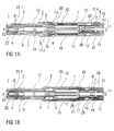
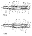
- FIGS 1 a and 1 b show two longitudinal sections of an auto-injector 1 in different section planes, the different section planes approximately 90° rotated to each other, wherein the auto-injector 1 is in an initial state prior to starting an injection.
- the auto-injector 1 comprises a chassis 2.
- the chassis 2 is generally considered as being fixed in position so motion of other components is described relative to the chassis 2.
- a syringe 3, e.g. a Hypak syringe, with a hollow injection needle 4 is arranged in a proximal part of the auto-injector 1.
- a protective needle sheath 5 is attached to the needle 4.
- a stopper 6 is arranged for sealing the syringe 3 distally and for displacing a liquid medicament M through the hollow needle 4.
- the syringe 3 is held in a tubular carrier 7 and supported at its proximal end therein.
- the carrier 7 is slidably arranged in the chassis 2.
- a drive spring 8 in the shape of a compression spring is arranged in a distal part of the carrier 7.
- a plunger 9 serves for forwarding the force of the drive spring 8 to the stopper 6.
- the drive spring 8 is loaded between a distal carrier end face 10 of the carrier 7 and a thrust face 11 arranged distally on the plunger 9.
- the carrier 7 is a key element housing the syringe 3, the drive spring 8 and the plunger 9, which are the components required to eject the medicament M from the syringe 3. These components can therefore be referred to as a drive sub-assembly.
- the chassis 2 and the carrier 7 are arranged within a tubular case 12.
- a trigger button 13 is arranged at a distal end of the case 12.
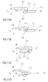
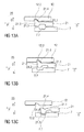
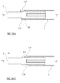
- a peg 14 protrudes from a distal end face of the trigger button 13 in the proximal direction P between two resilient arms 15 originating from the distal carrier end face 10 thus preventing them from flexing towards each other in an initial state A illustrated in figure 15A .
- FIG 15A only one of the resilient arms 15 is shown to illustrate the principle.
- the resilient arms 15 are caught in respective first recesses 16 in a distal plunger sleeve 17 attached distally to the thrust face 11 and arranged inside the drive spring 8.
- the engagement of the resilient arms 15 in the first recesses 16 prevents axial translation of the plunger 9 relative to the carrier 7.
- the resilient arms 15 are ramped in a manner to flex them inwards on relative motion between the plunger 9 and the carrier 7 under load of the drive spring 8, which is prevented by the peg 14 in the initial state A.
- the carrier 7 is locked to the chassis 2 for preventing relative translation by a detent mechanism 18 illustrated in more detail in figures 11A to 11D .
- the trigger button 13 is initially engaged to the case 12 by a button release mechanism 26 and cannot be depressed.
- the button release mechanism 26 is illustrated in detail in figures 16A to 16C .
- the button release mechanism 26 comprises a resilient proximal beam 13.1 on the trigger button 13, the proximal beam 13.1 having an outward first ramp 13.2 and an inward second ramp 13.3.
- the outward first ramp 13.2 is engaged in a ramped first case detent 12.1 preventing the trigger button 13 from moving out of the distal end D.
- the trigger button 13 proximally abuts both the case 12 and the carrier 7 hence being prevented from being depressed in the proximal direction P.
- a control spring 19 in the shape of another compression spring is arranged around the carrier 7 and acts between a proximal first collar 20 and a distal second collar 21.
- the control spring 19 is used to move the carrier 7 and hence the drive sub-assembly in the proximal direction P for needle insertion or in the distal direction D for needle retraction.
- a cap 22 is attached to the proximal end of the case 12 and the protective needle sheath 5 is still in place over the needle 4 and the needle hub.
- An inner sleeve 22.1 of the cap 22 is arranged inside the chassis 2 and over the protective needle sheath 5.
- a barb 23 is attached in the inner sleeve 22.1 . The barb 23 is engaged to the protective needle sheath 5 for joint axial translation.
- a sequence of operation of the auto-injector 1 is as follows:
- the user grabs the case 12 and places the chassis 2 protruding from the case 12 at the proximal end P against an injection site, e.g. a patient's skin.
- an injection site e.g. a patient's skin.
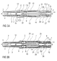
- the case 12 translates in the proximal direction P relative to the chassis 2 into an advanced position as illustrated in figures 3A and 3B .
- the second collar 21 is locked to the case 12 and is moved with the case 12 relative to the chassis 2 and relative to nearly all other components of the auto-injector 1 thus slightly compressing the control spring 19 against the first collar 20 which is prevented from moving in the proximal direction P by the chassis 2 due to a needle insertion control mechanism 24 being in a state A illustrated in detail in figure 12A .
- a resilient member in the shape of an arrowhead 20.1 is proximally arranged on the first collar 20. The first collar 20 with the arrowhead 20.1 is being forced in the proximal direction P under load of the compressed control spring 19.
- An outward sixth ramp 20.2 on the arrowhead 20.1 interacts with a second distal seventh ramp 2.4 on the chassis 2 ramping the arrowhead 20.1 in an inward direction I which is prevented by the arrowhead 20.1 inwardly abutting the carrier 7. Hence, the first collar 20 cannot translate in the proximal direction P.
- the second collar 21 is locked to the case due to a syringe retraction control mechanism 25 being in a state A illustrated in detail in figure 13A .
- the syringe retraction control mechanism 25 comprises a resilient proximal beam 21.1 on the second collar 21, the proximal beam 21.1 having a second beam head 21.2 having an inward boss 21.3 and a distal outward eighth ramp 21.4.
- the distal outward eighth ramp 21.4 is engaged in a ramped second case detent 12.2 in a manner ramping the second beam head 21.1 in the inward direction I with the second collar 21 under load of the control spring 19 in the distal direction D which is prevented by the inward boss 21.3 inwardly abutting the carrier 7.
- control spring 19 expands returning the auto-injector 1 to the initial condition after removal of the cap 22 as illustrated in figures 2A and 2B .
- the ramp on the first case detent 12.1 interacts with the outward first ramp 13.2 on the proximal beam 13.1 on the trigger button 13 deflecting the proximal beam 13.1 in the inward direction I thus engaging the inward second ramp 13.3 on the proximal beam 13.1 in a ramped carrier detent 7.4 arranged in the carrier 7.
- the case 12 is translated further in the proximal direction P it supports the proximal beam 13.1 outwardly thus locking the trigger button 13 to the carrier 7.
- the trigger button 13 now protrudes from the distal end D of the chassis 12 and is ready to be pressed.
- the user depresses the trigger button 13 in the proximal direction P.
- the carrier 7 As the trigger button 13 abuts against the carrier 7 the carrier 7 is pushing in the proximal direction P against the chassis 2, the carrier 7 and the chassis 2 interacting in the detent mechanism 18.
- the force exerted by the user pressing the trigger button 13 is resolved through the chassis 2 onto the injection site, not between the trigger button 13 and the case 12.
- the detent mechanism 18 provides a resistive force when the user pushes the trigger button 13. Once the user applies a force which exceeds a pre-determined value the detent mechanism 18 releases, initiating the injection cycle.
- the resilient beam 2.1 on the chassis 2 begins to bow under load from the rhomboid ramp member 7.1 on the carrier 7, storing elastic energy.
- the proximal fourth ramp 7.2 on the ramp member 7.1 friction between the contacting faces of the first beam head 2.2 and the proximal fourth ramp 7.2 prevents movement of the first beam head 2.2 in the outward direction O until the straightening force in the resiliently deformed beam 2.1 is sufficiently large to overcome it.
- the resilient beam 2.1 is deflected in the outward direction O moving out of the way of the carrier 7 thus allowing the carrier 7 to translate in the proximal direction P.
- the needle insertion control mechanism 24 is switched to a state B as illustrated in figure 12B .
- the carrier 7 has been translated in the proximal direction P in such a manner that the arrowhead 20.1 on the first collar 20 is no longer inwardly supported. This may be achieved by a second recess 7.5 in the carrier 7.
- the arrowhead 20.1 is now deflected in the inward direction I into the second recess 7.5 under load of the control spring 19 arriving at a state C as illustrated in figure 12C .
- the first collar 20 is now decoupled from the chassis 2.
- the arrowhead 20.1 couples the first collar 20 to the carrier 7 by an inward ninth ramp 20.3 engaging a distal tenth ramp 7.6 on the carrier 7 at the proximal end of the second recess 7.5.
- the control spring 19 continues moving the carrier 7 in the proximal direction P from this point. Whilst the user advances the needle 4 by a proportion of its travel, the control spring 19 takes over insertion before the needle 4 protrudes from the proximal end P. Therefore the user experience is that of pressing a button, rather than manually inserting a needle.
- the detent mechanism 18 relies on the user applying a force rather than a displacement. Once the force applied exceeds the force required to switch the detent the user will push the trigger button 13 fully, ensuring that the first collar 20 will always switch. If the user fails to pass the detent, the trigger button 13 returns to its unused state ready for use as illustrated in figures 3A and 3B . This feature avoids the auto-injector 1 arriving in an undefined state.
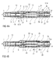
- Figures 4A and 4B show the auto-injector 1 with the trigger button 13 depressed sufficiently for the control spring 19 to couple on to the carrier 7 and continue moving the carrier 7 forwards, but not yet abutting the case 12.
- the carrier 7 coupled to the first collar 20 is translated in the proximal direction P driven by the control spring 19.
- the syringe 3 and needle 4 are also translated resulting in the needle 4 protruding from the proximal end P and being inserted into the injection site.
- the trigger button 13 returns to its initial position relative to the case 12 and latches back to the case 12 from the carrier 7 as in state A in figure 16A .
- the carrier 7 translates further in the proximal direction P preventing inward deflection of the proximal beam 13.1 so the outward first ramp 13.2 cannot disengage from the first case detent 12.1.
- the plunger release mechanism 27 arrives in a state B shown in figure 15B with the resilient arms 15 no longer inwardly supported by the peg 14. Due to the ramped engagement of the resilient arms 15 in the first recess 16 they are deflected in the inward direction I under load of the drive spring 8 arriving in a state B illustrated in figure 15C . Hence, the plunger 9 is released from the carrier 7 and driven in the proximal direction P by the drive spring 8, ready to inject the medicament M.
- the force to pull the peg 14 out from between the resilient arms 15 is provided by the control spring 19 while the force required to deflect the resilient arms 15 out of engagement to the plunger 9 is provided by the drive spring 8.
- the arrowhead 20.1 travels proximally beyond the part of the chassis 2 shown in figures 12A to 12F next to an aperture 2.5 in the chassis 2.
- the arrowhead 20.1 will be kept from deflecting in the outward direction O by a first rib 12.3 on the case 12 (not illustrated in figures 12A to F , see figures 5A to 8A ) during about the second half of its motion for needle insertion.
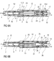
- the needle 4 is now fully inserted into the injection site as illustrated in figures 6A and 6B .
- the time between the trigger button 13 pressed and the needle 4 being fully inserted is very short, however several mechanical operations take place in this time.
- the needle insertion depth is defined by the carrier 7 relative to the chassis 2 not relative to the case 12, so if the user flinches or fails to hold the auto-injector 1 hard against the skin, only the case 12 will move in the distal direction D while the injection depth remains constant.
- the noise component 28 comprises an elongate portion 28.1 arranged within the distal plunger sleeve 17 and a distal end plate 28.2 arranged between the carrier end face 10 and an end face of the trigger button 13.
- Two second resilient arms 30 originate from the distal carrier end face 10 and extend in the proximal direction P.
- a noise spring 29 is arranged to bias the noise component 28 in the distal direction D relative to the carrier 7 by proximally bearing against a rib on the second resilient arms 30 and distally against the noise component 28 (not illustrated).
- the noise component 28 is not illustrated in figures 16A , B and C for clarity since it does not affect the function of the button release mechanism 26.
- a noise release mechanism 31 for releasing the noise component 28 is schematically illustrated in figures 14A, 14B and 14C .
- the noise release mechanism 31 comprises the second resilient arms 30.
- a ramped inward boss 30.1 is arranged on each second resilient arm 30 which is engaged to a respective outward eleventh ramp 28.3 on the elongate portion 28.1 of the noise component 28 in such a manner that the second resilient arm 30 is deflected in the outward direction O under load of the noise spring 29.
- the second resilient arms 30 are prevented from being outwardly deflected by outward support of the distal plunger sleeve 17 thus preventing translation of the noise component 28 relative to the carrier 7.
- the noise release mechanism 31 remains in state A until immediately prior to the end of injection with the stopper 6 having almost bottomed out in the syringe 3 as illustrated in figures 7A and 7B .
- the plunger 9 has been translated in the proximal direction P relative to the carrier 7 to such an extent that the second resilient arms 30 are no longer supported by the distal plunger sleeve 17.
- the noise release mechanism 31 has thus arrived in a state B illustrated in figure 14B .
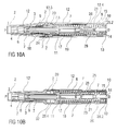
- FIGS. 8A and 8B show the auto-injector 1 with the stopper 6 having entirely bottomed out in the syringe 3.
- FIGS 9A and 9B show the auto-injector 1 lifted from the injection site with the case 12 moved all the way in the distal direction D so that the chassis 2 protrudes from the proximal end of the case 12.
- the first collar 20 releases the carrier 7 and then the second collar 21 releases from the case 12 and pulls the carrier 7 in the distal direction D.
- the sequencing of this switching is critical as retraction will fail if both collars 20, 21 are attached to the carrier 7 at the same time. This is overcome by separating the switching of the collars 20, 21 by a significant displacement of the case 12.
- FIGS. 12E and F The switching of the first collar 20 is illustrated in figures 12E and F .
- the case 12 has been allowed to move in the distal direction D under load of the control spring 19 during removal of the auto-injector 1 from the injection site.
- the first rib 12.3 (not illustrated, see figure 9A ) is removed from outwardly behind the arrowhead 20.1.
- the first collar 20 is still being pushed in the proximal direction P by the control spring 19.
- the syringe retraction control mechanism 25 switches from its state A (cf. figure 13A ) into a state B illustrated in figure 13B .
- the case 12 and the second collar 21 locked to the case 12 move together in the distal direction D while the carrier 7 is held in place by the detent mechanism 18 in its state C as described above (cf. figure 11 C) . Due to this motion the inward boss 21.3 on the second beam head 21.2 of the proximal beam 21.1 on the second collar 21 no longer inwardly abuts the carrier 7.
- the detent mechanism 18 applies a small retarding force to the movement of the carrier 7 before the syringe retraction control mechanism 25 switches to state C as there is a small sliding force, applied by the second collar 21, pulling the carrier 7 in the distal direction D on translation of the case 12 in the distal direction D when the needle insertion control mechanism 24 has already been switched into state E. If the carrier 7 moves too far in the distal direction D before the second collar 21 switches, the case 12 runs out of travel before the inward boss 21.3 can deflect into the third recess 7.7 preventing retraction.
- the carrier 7 and hence the rhomboid ramp member 7.1 are translated in the distal direction D under load of the control spring 19.
- the distal fifth ramp 7.3 of the rhomboid ramp member 7.1 engages the proximal third ramp 2.3 on the first beam head 2.2 of the resilient beam 2.1 in a manner deflecting the resilient beam 2.1 in the inward direction I. This applies the small retarding force to the movement of the carrier 7 required for ensuring the switching of the second collar 21 to the carrier 7.
- the resilient beam 2.1 and the rhomboid ramp member 7.1 are offset sideways to allow the resilient beam 2.1 to pass without contacting the rhomboid ramp member 7.1 as soon as the first beam head 2.2 is entirely inwardly from the ramp member 7.1 in a state D illustrated in figure 11D .
- the control spring 19 is grounded at its proximal end in the case by the first collar 20 being abutted against the chassis 2.
- the distal end of the control spring 19 moves the second collar 21 in the distal direction D taking with it the carrier 7 and hence the syringe 3 with the needle 4 overcoming the detent mechanism 18 as illustrated in figure 11D .
- the needle 4 is retracted out of the skin by the auto-injector 1 as soon as the user allows the case 12 to translate sufficiently far as opposed to auto-injectors with needle shields which require the user to remove the auto-injector from the injection site thereby themselves pulling the needle out of the skin for allowing the needle shield to advance.
- the noise component 28 As the movement allowed of the noise component 28 is limited relative to the carrier 7 it is no longer in contact with the trigger button 13 which has moved in the distal direction D with the case 12 on removal from the injection site. When the retraction begins the noise spring 29 does not provide any retarding force. Once the noise component 28 hits the trigger button 13 again on retraction of the carrier 7 the noise spring 29 must be recompressed, reducing the force driving the final part of retraction. In order to ensure a reliable retraction despite this reducing force the control spring 19 must be appropriately dimensioned.
- the arrowhead 20.1 on the first collar 20 is inwardly supported by the carrier 7 in a state F illustrated in figure 12F and thus prevented from deflecting in the inward direction I.
- the outward sixth ramp 20.2 of the arrowhead 20.1 is engaged behind the first rib 12.3 on the case 12 preventing the case 12 from being pushed in the proximal direction P again.
- a clearance may be provided between the arrowhead 20.1 and the first rib 12.3 to allow for tolerances.
- the detent mechanism 18 returns to state A as in figure 11A locking the carrier 7 in position relative to the chassis 2 as it did initially, however it cannot be unlocked now as the case 12 cannot move relative to the chassis 2.
- a tab 20.4 on the first collar 20 is now visible through an indicator window 32 in the case 12 ⁇ indicating the auto-injector 1 has been used.
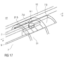
- Figure 17 is an isometric view of an alternative embodiment of the plunger release mechanism 27.
- the plunger release mechanism 27 prevents movement of the plunger 9 in the proximal direction P relative to the carrier 7 until the carrier 7 is moved in the proximal direction P for needle insertion.
- the alternative embodiment of figure 17 releases the plunger 9 by movement of the carrier 7 relative to the second collar 21.
- Figure 17 illustrates the plunger release mechanism 27 prior to plunger release.
- the second collar 21 is shown transparent to improve clarity.
- the plunger 9 is being pushed in the proximal direction P by the drive spring 8.
- the plunger 9 In order for the plunger 9 to advance, it must rotate around a twelfth ramp 7.8 on the carrier 7. A ramp member 9.1 on the plunger 9 is arranged to engage this twelfth ramp 7.8. Rotation of the ramp member 9.1 is blocked by an inward longitudinal rib 21.5 on the second collar 21 splined in a longitudinal aperture 7.9 in the carrier 7. The case 12 and the second collar 21 remain in the same position, i.e. coupled to each other for joint axial translation. On depression of the trigger button 13 the carrier 13 and the plunger 9 being part of the drive sub-assembly are moved in the proximal direction P, first by the user pressing the trigger button 13 and then by the control spring 19 taking over via the first collar 20 as described above.
- the ramp member 9.1 on the collar 9 comes clear of the longitudinal rib 21.5 on the second collar 21 and can rotate past the proximal end of the longitudinal rib 21.5 due to its ramped engagement to the twelfth ramp 7.8 under load of the drive spring 8.
- the drive spring 8 advances the plunger 9 in the proximal direction P for injecting the medicament M.
- Figure 18 is a longitudinal section of an alternative embodiment of the button release mechanism 26.
- the button release mechanism 26 of figure 16 which gives the appearance of a revealing trigger button 13 on skin contact by switching the ground of the trigger button 13 between the carrier 7 and the case 12, the button release mechanism 26 of figure 18 starts with the trigger button 13 locked but protruding from the distal end of the case 12.
- the trigger button 13 has two proximal beams 13.1, each of them having a ramped outward boss 13.4.
- the ramped outward bosses 13.4 are engaged in respective fourth recesses 12.5 in the case 12.
- Disengaging the ramped outward bosses 13.4 from the fourth recesses 12.5 is prevented by the carrier 7 inwardly supporting the proximal beams 13.1 in a manner to keep the proximal beams 13.1 from deflecting inwardly.
- Inward protrusions 13.5 on the proximal beams 13.1 abut against a second rib 7.10 on the carrier 7 in a manner preventing the carrier 7 from moving further in the proximal direction P in the initial state.
- a first window 7.11 in the carrier 7 is moved behind the inward protrusion 13.5 so as to allow the proximal beams 13.1 to be inwardly deflected due to their ramped engagement in the fourth recesses 12.5 on depression of the trigger button 13.
- the proximal beams 13.1 are now outwardly supported by the case 12 and remain engaged to the carrier 7 even on retraction of the needle 4.
- the trigger button 13 does therefore not return to its initial position, indicating that the auto-injector 1 has been used.
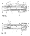
- Figures 19A and 19B show two longitudinal sections of an alternative embodiment of the detent mechanism 18.
- the detent mechanism 18 of figures 11A to 11D which may be referred to as a "race track" mechanism because of the first beam head 2.2 travelling around the rhomboid ramp member 7.1 has multiple functions which control the movement of the carrier 7 relative to the chassis 2.
- the alternative detent mechanism 18 of figures 19A and 19B uses three clips 7.12, 7.13, 2.6 to produce the same effect.
- the first clip 7.12 is arranged as an outwardly biased resilient beam on the carrier 7 extending from the carrier 7 in the proximal direction P.
- the first clip 7.12 is arranged to prevent the carrier 7 from being moved in the proximal direction P prior to the chassis 2 being depressed or rather the case 12 being translated on skin contact.
- the first clip 7.12 is composed of two sections side by side. A first section 7.14 prevents movement of the carrier 7 in the proximal direction P by abutting the chassis 2 in a recess.
- a second section 7.15 is arranged as an outwardly protruding clip head arranged to be ramped inwards by a ramp feature 12.6 on the chassis 12 for releasing the first clip 7.12 thereby unlocking the carrier 7 from the chassis 2 when the case 12 is being translated in the proximal direction P on skin contact.
- a longitudinal slot 2.7 in the chassis 2 is arranged for allowing the second section 7.15 to slide in the proximal direction P once the lock has been released.
- a slight friction force between the first clip 7.12 and the chassis 2 provides the retarding force required to ensure retraction.
- the second clip 7.13 is arranged as a resilient beam on the carrier 7 extending in the distal direction D having an outwardly protruding third beam head 7.16 with a proximal ramp.
- the third beam head 7.16 serves as a back stop against a third rib 2.9 on the chassis 2 for preventing the carrier 7 moving in the distal direction D from its initial position.
- the carrier 7 and chassis 2 are assembled with the second clip 7.13 in this position prior to inserting the syringe 3 into the carrier 7 which is facilitated by the proximal ramp on the third beam head 7.16.
- the syringe 3 locks the clip in place by preventing inward deflection thus creating a fixed stop.
- the third clip 2.6 is a resilient beam on the chassis 2 extending in the distal direction D.
- a ramped fourth beam head 2.8 on the third clip 2.6 is arranged to inwardly engage in a fifth recess 7.17 in the carrier 7.
- Figure 20 is a longitudinal section of a third embodiment of the detent mechanism 18 which is a variation on the embodiment of figures 19A and 19B .
- the detent function of the third clip 2.6 has been added into the first clip 7.12.
- the lock between the case 12 and the carrier 7 is released in the same way, but the detent is provided by deflecting the first clip 7.12 inwards a second level which is achieved by the chassis 2 not having a slot 2.7 for the second section 7.15.
- the second section 7.15 once ramped inwards by the ramp feature 12.6 on the case 12 has to be further ramped inwards inside the chassis 2 on axial load between the chassis 2 and the carrier 7, suddenly releasing their engagement.
- Figure 21 is a longitudinal section of an alternative embodiment of the noise release mechanism 31.
- the noise spring 29 acts between the carrier 7 and the noise component 28.
- the noise spring 29 acts between the case 12 and the noise component 28.
- the noise spring 29 is compressed as the noise component 28 moves with the carrier 7 relative to the case 12.
- the noise component 28 moves in the distal direction D and impacts the trigger button 13.
- the noise spring 29 is not being recompressed during needle retraction since it is grounded in the case 12 not in the carrier 7.
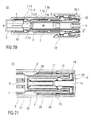
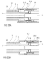
- Figures 22A and 22B show longitudinal sections of an alternative embodiment of the needle insertion control mechanism 24 which is also arranged to perform the detent function of the detent mechanism 18 on needle retraction and needle insertion.
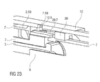
- Figure 23 shows a corresponding isometric view.
- a fourth clip 20.5 on the first collar 20 is arranged as a resilient beam with a beam head having an inward proximal thirteenth ramp 20.6 for engaging a fourth rib 7.18 on the carrier 7 and outwardly supported by the case 12 so as to keep the first collar 20 engaged to the carrier 7 prior to use, during needle insertion and during injection.
- a sixth recess 12.7 in the case 12 is moved outwardly behind the fourth clip 20.5 allowing the fourth clip 20.5 to release when the carrier 7 is pulled in the distal direction D by the second collar 21. Since the fourth clip 20.5 has to be ramped outwards a small force is required to release the fourth clip 20.5, providing the retraction detent.
- a fifth clip 2.10 on the chassis 2 abuts a block 20.7 on the first collar 20 prior to use preventing the first collar 20 and hence the carrier 7 engaged to the first collar 20 from moving in the proximal direction P.
- the fifth clip 2.10 In order to release, the fifth clip 2.10 must be deflected outwards and over the block 20.7. Outward deflection of the fifth clip 2.10 is initially prevented by the case 12. Once the case 12 has moved on skin contact a second window 12.8 in the case 12 appears outwardly from the fifth clip 2.10 allowing outward deflection.
- the fifth clip 2.10 is then deflected by a fourteenth ramp 7.19 on the carrier 7 when the carrier 7 is pushed in the proximal direction P on button depression as the fourth clip 20.5 does allow translation of the carrier 7 in the proximal direction P relative to the first collar 20 but not the other way round.
- the detent for needle insertion is provided by having to deflect the fifth clip 2.10 when it is loaded by the control spring 19.
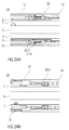
- Figures 24A and 24B show longitudinal sections of a third embodiment of the needle insertion control mechanism 24, also arranged to perform the functions of the detent mechanism 18.
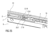
- Figure 25 is an isometric view of the needle insertion control mechanism 24 of figure 24 .
- the embodiment is similar to that illustrated in figures 22A, 22B and 23 . The difference is that the fifth clip 2.10 is arranged on the first collar 20 and the block 20.7 is arranged on the chassis 2, i.e. their position has been switched, so there are two clips 2.10 and 20.5 on the first collar 20.
- the fourth clip 20.5 is identical to that in figure 22B . It keeps the first collar 20 connected to the carrier 7 until the needle retraction is triggered, ensuring full injection depth is reached and maintained until the retraction cycle is initiated by removing the auto-injector 1 from the skin.
- the fifth clip 2.10 provides the detent for needle insertion and releases the first collar 20 from the chassis 2, initiating needle insertion.
- the fifth clip 2.10 prevents the first collar 20 and hence the carrier 7 engaged to the first collar 20 from moving in the proximal direction P prior to use by abutting the block 20.7 on the chassis 2.
- the fifth clip 2.10 In order to release, the fifth clip 2.10 must be deflected outwards and over the block 20.7. Outward deflection of the fifth clip 2.10 is initially prevented by the case 12. Once the case 12 has moved on skin contact the second window 12.8 in the case 12 appears outwardly from the fifth clip 2.10 allowing outward deflection.
- the fifth clip 2.10 is then deflected by the fourteenth ramp 7.19 on the carrier 7 when the carrier 7 is pushed in the proximal direction P on button depression as the fourth clip 20.5 does allow translation of the carrier 7 in the proximal direction P relative to the first collar 20 but not the other way round.
- the detent for needle insertion is provided by having to deflect the fifth clip 2.10 when it is loaded by the control spring 19.
- Figures 26A and 26B show a longitudinal section of a third embodiment of the noise release mechanism 31.
- This embodiment works without the need for a dedicated noise spring.
- the plunger 9 comprises a proximally ramped rib 9.2 arranged to splay two seventh clips 7.21 on the carrier 7 immediately prior to the end of dose. When the proximally ramped rib 9.2 has travelled past the seventh clips 7.21 they snap back and impact the plunger 9 generating a sound.
- the tubular shape of the carrier 7 helps to transmit the sound.
- Figure 26A shows the noise release mechanism 31 before release.
- Figure 26B shows the noise release mechanism 31 after release.
- Proximal faces of the seventh clips 7.21 on the carrier 7 are axially offset to facilitate assembly by lifting the seventh clips 7.21 over the distal side of the proximally ramped rib 9.2 one by one.
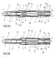
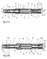
- Figures 27A and 27B show longitudinal sections of another embodiment of the auto-injector 1 in different section planes, the different section planes approximately 90° rotated to each other, wherein the auto-injector 1 is in an initial state prior to starting an injection.
- the auto-injector 1 is essentially identical to the one described in figures 1 to 16 .
- the auto-injector 1 of this embodiment has a wrap-over sleeve trigger instead of a trigger button.
- the wrap-over sleeve trigger 12 is the same component as the case 12 which has a closed distal end face 12.10 other than the one in figures 1 to 16 .
- An internal trigger button 13 is arranged at the distal end inside the sleeve trigger 12. Other than in figures 1 to 16 the trigger button 13 is not visible nor does it protrude from the case 12 in any state. In the initial state a clearance 33 is provided between the distal end face 12.10 of the sleeve trigger 12 and the internal trigger button 13 allowing for some travel of the sleeve trigger 12 without interfering with the trigger button 13.
- the detent mechanism 18 is arranged to provide a resistive force when the user reaches the second phase of sleeve travel. Internally, there is no difference to the embodiment of figures 1 to 16 at this point.
- Needle insertion is triggered by the user fully advancing the sleeve trigger 12 in the second face of sleeve travel thereby fully depressing the internal trigger button 13 and overcoming the detent mechanism as in the embodiment of figures 1 to 16 .
Landscapes
- Health & Medical Sciences (AREA)
- Engineering & Computer Science (AREA)
- Hematology (AREA)
- Anesthesiology (AREA)
- Biomedical Technology (AREA)
- Heart & Thoracic Surgery (AREA)
- Vascular Medicine (AREA)
- Life Sciences & Earth Sciences (AREA)
- Animal Behavior & Ethology (AREA)
- General Health & Medical Sciences (AREA)
- Public Health (AREA)
- Veterinary Medicine (AREA)
- Environmental & Geological Engineering (AREA)
- Infusion, Injection, And Reservoir Apparatuses (AREA)
Priority Applications (17)
| Application Number | Priority Date | Filing Date | Title |
|---|---|---|---|
| EP11155029A EP2489380A1 (fr) | 2011-02-18 | 2011-02-18 | Dispositif d'injection |
| CN201280019029.3A CN103492000B (zh) | 2011-02-18 | 2012-02-16 | 注射装置 |
| AU2012217076A AU2012217076B2 (en) | 2011-02-18 | 2012-02-16 | Injection device |
| ES12706008.5T ES2542010T3 (es) | 2011-02-18 | 2012-02-16 | Dispositivo de inyección |
| BR112013020870A BR112013020870A2 (pt) | 2011-02-18 | 2012-02-16 | dispositivo de injeção |
| PL12706008T PL2675509T3 (pl) | 2011-02-18 | 2012-02-16 | Urządzenie do zastrzyków |
| JP2013553926A JP6143680B2 (ja) | 2011-02-18 | 2012-02-16 | 注射デバイス |
| US14/000,113 US9155844B2 (en) | 2011-02-18 | 2012-02-16 | Injection device |
| CA2825788A CA2825788A1 (fr) | 2011-02-18 | 2012-02-16 | Dispositif d'injection |
| HUE12706008A HUE025734T2 (en) | 2011-02-18 | 2012-02-16 | Injection device |
| EP12706008.5A EP2675509B1 (fr) | 2011-02-18 | 2012-02-16 | Dispositif d'injection |
| ARP120100519A AR085254A1 (es) | 2011-02-18 | 2012-02-16 | Dispositivo de inyeccion |
| DK12706008.5T DK2675509T3 (en) | 2011-02-18 | 2012-02-16 | INJECTION DEVICE |
| PCT/EP2012/052639 WO2012110572A1 (fr) | 2011-02-18 | 2012-02-16 | Dispositif d'injection |
| IL227659A IL227659A (en) | 2011-02-18 | 2013-07-25 | Device for injection |
| HK14101337.4A HK1188155A1 (en) | 2011-02-18 | 2014-02-13 | Injection device |
| US14/879,805 US10518041B2 (en) | 2011-02-18 | 2015-10-09 | Injection device |
Applications Claiming Priority (1)
| Application Number | Priority Date | Filing Date | Title |
|---|---|---|---|
| EP11155029A EP2489380A1 (fr) | 2011-02-18 | 2011-02-18 | Dispositif d'injection |
Publications (1)
| Publication Number | Publication Date |
|---|---|
| EP2489380A1 true EP2489380A1 (fr) | 2012-08-22 |
Family
ID=49080496
Family Applications (2)
| Application Number | Title | Priority Date | Filing Date |
|---|---|---|---|
| EP11155029A Ceased EP2489380A1 (fr) | 2011-02-18 | 2011-02-18 | Dispositif d'injection |
| EP12706008.5A Active EP2675509B1 (fr) | 2011-02-18 | 2012-02-16 | Dispositif d'injection |
Family Applications After (1)
| Application Number | Title | Priority Date | Filing Date |
|---|---|---|---|
| EP12706008.5A Active EP2675509B1 (fr) | 2011-02-18 | 2012-02-16 | Dispositif d'injection |
Country Status (14)
| Country | Link |
|---|---|
| US (2) | US9155844B2 (fr) |
| EP (2) | EP2489380A1 (fr) |
| JP (1) | JP6143680B2 (fr) |
| CN (1) | CN103492000B (fr) |
| AR (1) | AR085254A1 (fr) |
| BR (1) | BR112013020870A2 (fr) |
| CA (1) | CA2825788A1 (fr) |
| DK (1) | DK2675509T3 (fr) |
| ES (1) | ES2542010T3 (fr) |
| HK (1) | HK1188155A1 (fr) |
| HU (1) | HUE025734T2 (fr) |
| IL (1) | IL227659A (fr) |
| PL (1) | PL2675509T3 (fr) |
| WO (1) | WO2012110572A1 (fr) |
Cited By (27)
| Publication number | Priority date | Publication date | Assignee | Title |
|---|---|---|---|---|
| CN103170038A (zh) * | 2013-02-22 | 2013-06-26 | 杭州金源生物技术有限公司 | 一种胰岛素注射笔 |
| FR2995790A1 (fr) * | 2012-09-27 | 2014-03-28 | Aptar France Sas | Autoinjecteur |
| WO2014049214A1 (fr) * | 2012-09-27 | 2014-04-03 | Aptar France Sas | Autoinjecteur |
| EP2742962A3 (fr) * | 2013-03-22 | 2014-07-23 | TecPharma Licensing AG | Auto-injecteur doté d'un dispositif de signalisation à la fin de la distribution de produit |
| FR3003470A1 (fr) * | 2013-03-21 | 2014-09-26 | Aptar France Sas | Autoinjecteur |
| WO2014195183A1 (fr) * | 2013-06-03 | 2014-12-11 | Novo Nordisk A/S | Dispositif d'injection médical |
| EP2823837A1 (fr) * | 2013-07-09 | 2015-01-14 | Sanofi-Aventis Deutschland GmbH | Auto-injecteur |
| EP2823836A1 (fr) * | 2013-07-09 | 2015-01-14 | Sanofi-Aventis Deutschland GmbH | Auto-injecteur |
| EP2823839A1 (fr) * | 2013-07-09 | 2015-01-14 | Sanofi-Aventis Deutschland GmbH | Auto-injecteur |
| EP2829290A1 (fr) * | 2013-07-25 | 2015-01-28 | Sanofi-Aventis Deutschland GmbH | Mécanisme d'entraînement pour dispositif d'administration de médicaments |
| WO2015018578A1 (fr) * | 2013-08-08 | 2015-02-12 | Carebay Europe Ltd | Unité motrice |
| CN105324141A (zh) * | 2013-06-24 | 2016-02-10 | 医药咨询有限责任公司 | 用于自动注射器的激活器 |
| US9616174B2 (en) | 2012-05-25 | 2017-04-11 | Aptar France Sas | Autoinjector |
| WO2017160626A1 (fr) * | 2016-03-16 | 2017-09-21 | Eli Lilly And Company | Ensemble déclencheur pour dispositif d'injection automatique de médicament |
| WO2018167494A1 (fr) * | 2017-03-15 | 2018-09-20 | Owen Mumford Limited | Dispositif d'injection |
| WO2018167493A1 (fr) * | 2017-03-15 | 2018-09-20 | Owen Mumford Limited | Dispositif d'injection à mécanisme de réduction d'espace |
| US10245388B2 (en) | 2013-08-08 | 2019-04-02 | Global Bio Therapeutics, Inc. | Injection device for minimally invasive procedures and uses thereof |
| EP3402556A4 (fr) * | 2016-01-12 | 2019-08-07 | Pharma Consult Ges.m.b.H. | Dspositif d'injection |
| EP3610908A1 (fr) * | 2014-07-29 | 2020-02-19 | TecPharma Licensing AG | Auto-injecteur avec protecteur d'aiguille mobile |
| WO2020035513A1 (fr) * | 2018-08-13 | 2020-02-20 | Sanofi | Dispositif d'injection |
| US10864326B2 (en) | 2016-03-16 | 2020-12-15 | Eli Lilly And Company | Medication injection device with automatic needle retraction following injection |
| US10888669B2 (en) | 2015-06-03 | 2021-01-12 | Sanofi-Aventis Deutschland Gmbh | Drug delivery device with audible indicator spring |
| EP3768357A4 (fr) * | 2018-03-22 | 2022-01-05 | BDRtech LLC | Dispositif d'auto-injection |
| US11364032B2 (en) | 2013-08-08 | 2022-06-21 | Global Bio Therapeutics, Inc. | Clamp device for minimally invasive procedures and uses thereof |
| US11376364B2 (en) | 2017-03-15 | 2022-07-05 | Owen Mumford Limited | Injection apparatus |
| CN114929310A (zh) * | 2018-10-05 | 2022-08-19 | 辉美医疗器械有限公司 | 自动注射装置和盒子 |
| WO2023094148A1 (fr) * | 2021-11-23 | 2023-06-01 | Shl Medical Ag | Composants et sous-ensembles pour dispositifs d'administration de médicament |
Families Citing this family (55)
| Publication number | Priority date | Publication date | Assignee | Title |
|---|---|---|---|---|
| IL157981A (en) | 2003-09-17 | 2014-01-30 | Elcam Medical Agricultural Cooperative Ass Ltd | Auto injector |
| GB2414400B (en) | 2004-05-28 | 2009-01-14 | Cilag Ag Int | Injection device |
| GB2414402B (en) | 2004-05-28 | 2009-04-22 | Cilag Ag Int | Injection device |
| GB2414775B (en) | 2004-05-28 | 2008-05-21 | Cilag Ag Int | Releasable coupling and injection device |
| GB2424836B (en) | 2005-04-06 | 2010-09-22 | Cilag Ag Int | Injection device (bayonet cap removal) |
| GB2425062B (en) | 2005-04-06 | 2010-07-21 | Cilag Ag Int | Injection device |
| US20110098656A1 (en) | 2005-09-27 | 2011-04-28 | Burnell Rosie L | Auto-injection device with needle protecting cap having outer and inner sleeves |
| GB2438591B (en) | 2006-06-01 | 2011-07-13 | Cilag Gmbh Int | Injection device |
| GB2461085B (en) | 2008-06-19 | 2012-08-29 | Cilag Gmbh Int | Injection device |
| EP2399635A1 (fr) | 2010-06-28 | 2011-12-28 | Sanofi-Aventis Deutschland GmbH | Auto-injecteur |
| EP2489380A1 (fr) * | 2011-02-18 | 2012-08-22 | Sanofi-Aventis Deutschland GmbH | Dispositif d'injection |
| EP2489387A1 (fr) | 2011-02-18 | 2012-08-22 | Sanofi-Aventis Deutschland GmbH | Auto-injecteur |
| EP2489381A1 (fr) | 2011-02-18 | 2012-08-22 | Sanofi-Aventis Deutschland GmbH | Auto-injecteur |
| EP2489390A1 (fr) | 2011-02-18 | 2012-08-22 | Sanofi-Aventis Deutschland GmbH | Mécanisme d'encliquetage |
| EP2489384A1 (fr) | 2011-02-18 | 2012-08-22 | Sanofi-Aventis Deutschland GmbH | Auto-injecteur |
| EP2489386A1 (fr) | 2011-02-18 | 2012-08-22 | Sanofi-Aventis Deutschland GmbH | Auto-injecteur |
| EP2489389A1 (fr) | 2011-02-18 | 2012-08-22 | Sanofi-Aventis Deutschland GmbH | Mécanisme d'encliquetage |
| EP2489382A1 (fr) | 2011-02-18 | 2012-08-22 | Sanofi-Aventis Deutschland GmbH | Auto-injecteur |
| EP2489388A1 (fr) | 2011-02-18 | 2012-08-22 | Sanofi-Aventis Deutschland GmbH | Auto-injecteur |
| EP2489385A1 (fr) | 2011-02-18 | 2012-08-22 | Sanofi-Aventis Deutschland GmbH | Auto-injecteur |
| EP2854899B1 (fr) * | 2012-05-25 | 2017-07-12 | Aptar France SAS | Autoinjecteur |
| AU2013366011A1 (en) | 2012-11-09 | 2015-05-28 | Iinjec Technologies Inc. | Fluid delivery device and method |
| JP6456928B2 (ja) * | 2013-06-04 | 2019-01-23 | ノボ・ノルデイスク・エー/エス | 投与終了機構を有するねじりばね式注射装置 |
| GB2515039B (en) | 2013-06-11 | 2015-05-27 | Cilag Gmbh Int | Injection Device |
| GB2515038A (en) | 2013-06-11 | 2014-12-17 | Cilag Gmbh Int | Injection device |
| GB2517896B (en) | 2013-06-11 | 2015-07-08 | Cilag Gmbh Int | Injection device |
| GB2515032A (en) | 2013-06-11 | 2014-12-17 | Cilag Gmbh Int | Guide for an injection device |
| EP2823841A1 (fr) | 2013-07-09 | 2015-01-14 | Sanofi-Aventis Deutschland GmbH | Auto-injecteur |
| FR3016523B1 (fr) * | 2014-01-20 | 2017-08-11 | Biocorp Rech Et Dev | Injecteur automatique |
| EP2923714A1 (fr) | 2014-03-28 | 2015-09-30 | Sanofi-Aventis Deutschland GmbH | Auto-injecteur declenché par contact avec la peau |
| GB2530714A (en) | 2014-08-20 | 2016-04-06 | Owen Mumford Ltd | Injection devices |
| BR112017011213A2 (pt) | 2014-12-23 | 2018-02-14 | Automed Pty Ltd | aparelho de fornecimento, sistema e métodos associados |
| US10182969B2 (en) | 2015-03-10 | 2019-01-22 | Regeneron Pharmaceuticals, Inc. | Aseptic piercing system and method |
| TW201707741A (zh) | 2015-06-03 | 2017-03-01 | 賽諾菲阿凡提斯德意志有限公司 | 針頭護罩之抓握器、蓋子、自動注射器及製造抓握器之方法 |
| TW201707740A (zh) | 2015-06-03 | 2017-03-01 | 賽諾菲阿凡提斯德意志有限公司 | 藥物輸送裝置(四) |
| CN109152881B (zh) * | 2016-05-06 | 2021-11-02 | 艾斯曲尔医疗公司 | 用于药剂输送装置的驱动组件 |
| CN109310822A (zh) * | 2016-05-16 | 2019-02-05 | 艾斯曲尔医疗公司 | 注射装置 |
| EP3519016A1 (fr) * | 2016-09-27 | 2019-08-07 | Sanofi-Aventis Deutschland GmbH | Dispositif d'administration de médicament |
| GB201616712D0 (en) | 2016-09-30 | 2016-11-16 | Owen Mumford Ltd | Injection devices |
| GB201704140D0 (en) * | 2017-03-15 | 2017-04-26 | Owen Mumford Ltd | Injection device with velocity regulator |
| ES2919934T3 (es) | 2017-05-05 | 2022-07-29 | Regeneron Pharma | Autoinyector y procedimientos de uso relacionados |
| US20200276388A1 (en) * | 2017-11-17 | 2020-09-03 | Sanofi | Device and mixing and/or reconstitution method |
| BR112022005836A2 (pt) * | 2019-09-30 | 2022-06-21 | Amgen Inc | Dispositivo de administração de fármaco |
| CN114867510A (zh) * | 2019-12-11 | 2022-08-05 | 赛诺菲 | 注射装置 |
| US12005244B2 (en) | 2020-03-27 | 2024-06-11 | Medivena Sp. Z O.O. | Needle-based device based on direct wing-based coupling of a needle shield to a barrel thereof and safety mechanism implemented therein |
| KR102251405B1 (ko) | 2020-04-09 | 2021-05-12 | (주)풍림파마텍 | 자동 주사장치 |
| US11957542B2 (en) | 2020-04-30 | 2024-04-16 | Automed Patent Holdco, Llc | Sensing complete injection for animal injection device |
| WO2022077910A1 (fr) * | 2020-10-16 | 2022-04-21 | 山东威高普瑞医药包装有限公司 | Seringue automatique |
| CN116528929A (zh) * | 2020-12-02 | 2023-08-01 | 赛诺菲 | 用于药物递送装置的组件和药物递送装置 |
| CN113209422B (zh) * | 2021-05-20 | 2022-10-14 | 宁波睿爱产品设计有限公司 | 一种具有声音提示功能的注射装置 |
| CN113209423B (zh) * | 2021-05-20 | 2022-10-14 | 宁波睿爱产品设计有限公司 | 具有声音提示功能的自动注射装置 |
| CN113368343B (zh) * | 2021-05-26 | 2022-06-10 | 宁波易舒医疗科技有限公司 | 一种推力机构、应用该机构的自动注射装置及其使用方法 |
| EP4419175A1 (fr) * | 2021-10-19 | 2024-08-28 | SHL Medical AG | Mécanisme de rétroaction automatique pour dispositif d'administration de médicament |
| USD1007676S1 (en) | 2021-11-16 | 2023-12-12 | Regeneron Pharmaceuticals, Inc. | Wearable autoinjector |
| KR102694750B1 (ko) | 2023-03-30 | 2024-08-14 | 주식회사 비에스엘 | 청각 피드백을 제공하는 자동 약물 주입 장치 |
Citations (4)
| Publication number | Priority date | Publication date | Assignee | Title |
|---|---|---|---|---|
| US20020095120A1 (en) | 2000-08-29 | 2002-07-18 | Andre Larsen | Automatic injection device |
| US20050027255A1 (en) * | 2003-07-31 | 2005-02-03 | Sid Technologies, Llc | Automatic injector |
| US20090012479A1 (en) * | 2005-01-25 | 2009-01-08 | Novo Nordisk A/S | Injection Device with an End of Dose Feedback Mechanism |
| WO2010035059A1 (fr) * | 2008-09-29 | 2010-04-01 | Becton Dickinson France | Dispositif d'injection automatique équipé d'une indication sonore indiquant la fin de l'injection |
Family Cites Families (76)
| Publication number | Priority date | Publication date | Assignee | Title |
|---|---|---|---|---|
| GB8926825D0 (en) | 1989-11-28 | 1990-01-17 | Glaxo Group Ltd | Device |
| US6287610B1 (en) | 1991-11-20 | 2001-09-11 | Monfort, Inc. | Method for increasing the tenderness of a meat product |
| WO1994011041A1 (fr) | 1992-11-19 | 1994-05-26 | R G S.A.S. Di Rosaria Galli & C. | Auto-injecteur jetable pour seringues preremplies |
| US5320609A (en) | 1992-12-07 | 1994-06-14 | Habley Medical Technology Corporation | Automatic pharmaceutical dispensing syringe |
| EP0693946B1 (fr) | 1993-03-24 | 2001-05-16 | Owen Mumford Limited | Amelioration concernant des dispositifs d'injection |
| US5478316A (en) | 1994-02-02 | 1995-12-26 | Becton, Dickinson And Company | Automatic self-injection device |
| WO1996027400A1 (fr) | 1995-03-07 | 1996-09-12 | Eli Lilly And Company | Distributeur recyclable de medicament |
| FR2733155B1 (fr) | 1995-04-18 | 1997-09-19 | Tebro | Auto-injecteur rechargeable |
| US5746215A (en) | 1996-11-01 | 1998-05-05 | U.S. Medical Instruments, Inc. | IV infusion or collection device with extendable and retractable needle |
| SE9803662D0 (sv) | 1998-10-26 | 1998-10-26 | Pharmacia & Upjohn Ab | Autoinjector |
| FR2787246B1 (fr) | 1998-12-09 | 2001-02-23 | Alpes Lasers | Laser de type semi-conducteur |
| WO2002009797A1 (fr) | 2000-08-02 | 2002-02-07 | Becton Dickinson And Company | Aiguille stylo et systeme de blindage de securite |
| PT1326664E (pt) | 2000-10-09 | 2006-12-29 | Lilly Co Eli | Dispositivo tipo caneta para a administração de hormona paratiróide |
| JP4659332B2 (ja) | 2000-10-13 | 2011-03-30 | アルザ・コーポレーシヨン | 微小突起を用いて皮膚を穿孔するための装置および方法 |
| SE518981C2 (sv) | 2000-12-14 | 2002-12-17 | Shl Medical Ab | Autoinjektor |
| US6461362B1 (en) | 2001-04-30 | 2002-10-08 | Mdc Investment Holdings, Inc. | Catheter insertion device with retractable needle |
| JP4339260B2 (ja) | 2002-11-25 | 2009-10-07 | テクファーマ・ライセンシング・アクチェンゲゼルシャフト | 針保護装置を有する注射装置 |
| GB0312852D0 (en) | 2003-06-05 | 2003-07-09 | Owen Mumford Ltd | Improvements relating to syringe firing mechanisms |
| DE10342059B4 (de) | 2003-09-11 | 2007-03-01 | Tecpharma Licensing Ag | Verabreichungsvorrichtung mit Einstech- und Ausschütteinrichtung |
| DE10351599A1 (de) | 2003-11-05 | 2005-06-16 | Tecpharma Licensing Ag | Autoinjektionsvorrichtung |
| US20050101919A1 (en) | 2003-11-07 | 2005-05-12 | Lennart Brunnberg | Device for an injector |
| CH696421A5 (de) | 2003-12-18 | 2007-06-15 | Tecpharma Licensing Ag | Autoinjektor mit Arretierung des Wirkstoffbehälters. |
| EP1715903B1 (fr) | 2004-01-23 | 2007-10-24 | The Medical House Plc | Dispositif d'injection |
| GB2410188B (en) * | 2004-01-23 | 2006-01-25 | Medical House Plc | Injection device |
| US20050222539A1 (en) | 2004-03-30 | 2005-10-06 | Pediamed Pharmaceuticals, Inc. | Automatic injection device |
| US7160219B2 (en) | 2004-06-03 | 2007-01-09 | Arvinmeritor Technology Llc. | Method and apparatus for lubricating a differential gear assembly |
| US9220595B2 (en) | 2004-06-23 | 2015-12-29 | Orthovita, Inc. | Shapeable bone graft substitute and instruments for delivery thereof |
| US8048035B2 (en) | 2004-08-06 | 2011-11-01 | Meridian Medical Technologies, Inc. | Automatic injector with needle cover |
| DE102004041151A1 (de) | 2004-08-25 | 2006-03-02 | Tecpharma Licensing Ag | Dosiervorrichtung mit Ablaufsteuerung |
| EP1814616A1 (fr) | 2004-11-04 | 2007-08-08 | Sid Technologies Llc | Injecteur automatique |
| DE102004063644A1 (de) | 2004-12-31 | 2006-07-20 | Tecpharma Licensing Ag | Vorrichtung zur dosierten Verabreichung eines fluiden Produkts mit Drehfederantrieb |
| US7407494B2 (en) | 2005-01-31 | 2008-08-05 | Bostroem Anders | Device for delivering medicament |
| JP5222722B2 (ja) | 2005-04-20 | 2013-06-26 | ベクトン・ディキンソン・フランス・エス.エー.エス. | 注入セットおよび注入補助装置 |
| ATE436074T1 (de) | 2005-05-16 | 2009-07-15 | Mallinckrodt Inc | Radiopharmazeutischer container mit injektionsnadel-entkappungsvorrichtung |
| EP1893256B1 (fr) * | 2005-06-16 | 2012-09-26 | Novo Nordisk A/S | Procede et appareil d'aide a des patients pour l'auto-administration de medicaments |
| EP1904131A2 (fr) | 2005-06-21 | 2008-04-02 | Eli Lilly And Company | Appareil et procede d'injection de medicament |
| DE202005010389U1 (de) * | 2005-07-01 | 2005-09-08 | Tecpharma Licensing Ag | Magnetische Kolbenstangenrückführung und Kolbenstangenfixierung |
| DE102005052460A1 (de) | 2005-11-03 | 2007-05-16 | Tecpharma Licensing Ag | Autoinjektor - Ablaufsteuerung für Behältniswechsel |
| FR2899482A1 (fr) * | 2006-04-11 | 2007-10-12 | Becton Dickinson France Soc Pa | Dispositif d'injection automatique |
| FR2905273B1 (fr) | 2006-09-06 | 2009-04-03 | Becton Dickinson France Soc Pa | Dispositif d'injection automatique avec moyen de temporisation. |
| GB2443606B (en) | 2006-11-13 | 2011-07-20 | Cilag Gmbh Int | Injection device |
| ES2365931T3 (es) | 2006-12-13 | 2011-10-13 | Shl Group Ab | Inyector automático. |
| US20080228147A1 (en) * | 2007-03-15 | 2008-09-18 | Bristol-Myers Squibb Company | Injector for use with pre-filled syringes and method of assembly |
| DE102007013836A1 (de) | 2007-03-22 | 2008-09-25 | Tecpharma Licensing Ag | Injektionsvorrichtung mit gesteuertem Nadelrückzug |
| DE102007013838A1 (de) | 2007-03-22 | 2008-09-25 | Tecpharma Licensing Ag | Injektionsvorrichtung mit zeitkonstantem Ausschüttsignal |
| EP3865161A1 (fr) | 2007-03-22 | 2021-08-18 | Ypsomed AG | Dispositif d'injection à rétraction d'aiguille commandée |
| CN101678167B (zh) * | 2007-03-22 | 2013-09-18 | 特克法马许可公司 | 注射装置中的弹簧机构 |
| DE102007016811A1 (de) * | 2007-04-05 | 2008-10-09 | Tecpharma Licensing Ag | Vorrichtung zur Verabreichung eines fluiden Wirkstoffes aus einer Mehrkammerampulle |
| US8057427B2 (en) | 2007-05-09 | 2011-11-15 | Meridian Medical Technologies, Inc. | Drug delivery system with a small amount of a therapeutic agent |
| DE102007030327A1 (de) | 2007-06-29 | 2009-01-02 | Tecpharma Licensing Ag | Injektionsvorrichtung mit einer Feder für eine Nadelschutzhülse |
| US8491530B2 (en) | 2007-09-25 | 2013-07-23 | Becton Dickinson France | Autoinjector with trigger positionable in active position by movement of a safety shield and indication of the active position |
| WO2009040602A1 (fr) | 2007-09-25 | 2009-04-02 | Becton Dickinson France | Dispositif d'injection automatique équipé de moyen de désactivation rendu mobile par une protection de sécurité |
| EP2224980B1 (fr) | 2007-11-12 | 2018-07-25 | Medicom Innovation Partner a/s | Injecteur automatique avec points d'ancrage variables du propulseur mécanique |
| WO2009063030A1 (fr) | 2007-11-14 | 2009-05-22 | Shl Group Ab | Dispositif d'injection automatique comportant une fonction de retrait de seringue à déclenchement actif |
| US8771237B2 (en) | 2007-12-20 | 2014-07-08 | Novo Nordisk A/S | Injection device for delivering a fixed dose of liquid drug |
| GB0801874D0 (en) | 2008-02-01 | 2008-03-12 | Liversidge Barry P | Injection device |
| GB2460398A (en) * | 2008-05-20 | 2009-12-02 | Owen Mumford Ltd | Auto-injector having a magnetic injection indicator and a needle sheath retainer |
| EP2362795B1 (fr) | 2008-09-29 | 2018-04-25 | Becton Dickinson France | Dispositif d'injection automatique |
| GB2469672B (en) | 2009-04-23 | 2013-09-25 | Medical House Ltd | Improved autoinjector |
| US20100286612A1 (en) * | 2009-05-06 | 2010-11-11 | William Cirillo | Medication injection supervisor device |
| EP2485786B1 (fr) * | 2009-10-08 | 2020-08-19 | SHL Medical AG | Dispositif de distribution de médicaments |
| DK3025743T3 (en) * | 2010-02-09 | 2018-10-15 | Shl Group Ab | Drug delivery device |
| KR101725580B1 (ko) * | 2010-03-31 | 2017-04-10 | 에스에이치엘 그룹 에이비 | 약물 주입 장치 |
| EP2399635A1 (fr) | 2010-06-28 | 2011-12-28 | Sanofi-Aventis Deutschland GmbH | Auto-injecteur |
| GB201021767D0 (en) * | 2010-12-22 | 2011-02-02 | Owen Mumford Ltd | Autoinjectors |
| EP2489382A1 (fr) | 2011-02-18 | 2012-08-22 | Sanofi-Aventis Deutschland GmbH | Auto-injecteur |
| EP2489387A1 (fr) | 2011-02-18 | 2012-08-22 | Sanofi-Aventis Deutschland GmbH | Auto-injecteur |
| EP2489389A1 (fr) | 2011-02-18 | 2012-08-22 | Sanofi-Aventis Deutschland GmbH | Mécanisme d'encliquetage |
| EP2489390A1 (fr) | 2011-02-18 | 2012-08-22 | Sanofi-Aventis Deutschland GmbH | Mécanisme d'encliquetage |
| EP2489386A1 (fr) | 2011-02-18 | 2012-08-22 | Sanofi-Aventis Deutschland GmbH | Auto-injecteur |
| EP2489380A1 (fr) | 2011-02-18 | 2012-08-22 | Sanofi-Aventis Deutschland GmbH | Dispositif d'injection |
| EP2489381A1 (fr) | 2011-02-18 | 2012-08-22 | Sanofi-Aventis Deutschland GmbH | Auto-injecteur |
| EP2489388A1 (fr) | 2011-02-18 | 2012-08-22 | Sanofi-Aventis Deutschland GmbH | Auto-injecteur |
| EP2489384A1 (fr) | 2011-02-18 | 2012-08-22 | Sanofi-Aventis Deutschland GmbH | Auto-injecteur |
| EP2489383A1 (fr) | 2011-02-18 | 2012-08-22 | Sanofi-Aventis Deutschland GmbH | Auto-injecteur |
| EP2489385A1 (fr) | 2011-02-18 | 2012-08-22 | Sanofi-Aventis Deutschland GmbH | Auto-injecteur |
-
2011
- 2011-02-18 EP EP11155029A patent/EP2489380A1/fr not_active Ceased
-
2012
- 2012-02-16 US US14/000,113 patent/US9155844B2/en active Active
- 2012-02-16 HU HUE12706008A patent/HUE025734T2/en unknown
- 2012-02-16 WO PCT/EP2012/052639 patent/WO2012110572A1/fr active Application Filing
- 2012-02-16 DK DK12706008.5T patent/DK2675509T3/en active
- 2012-02-16 AR ARP120100519A patent/AR085254A1/es not_active Application Discontinuation
- 2012-02-16 BR BR112013020870A patent/BR112013020870A2/pt not_active IP Right Cessation
- 2012-02-16 EP EP12706008.5A patent/EP2675509B1/fr active Active
- 2012-02-16 ES ES12706008.5T patent/ES2542010T3/es active Active
- 2012-02-16 JP JP2013553926A patent/JP6143680B2/ja active Active
- 2012-02-16 PL PL12706008T patent/PL2675509T3/pl unknown
- 2012-02-16 CA CA2825788A patent/CA2825788A1/fr not_active Abandoned
- 2012-02-16 CN CN201280019029.3A patent/CN103492000B/zh active Active
-
2013
- 2013-07-25 IL IL227659A patent/IL227659A/en active IP Right Grant
-
2014
- 2014-02-13 HK HK14101337.4A patent/HK1188155A1/xx unknown
-
2015
- 2015-10-09 US US14/879,805 patent/US10518041B2/en active Active
Patent Citations (4)
| Publication number | Priority date | Publication date | Assignee | Title |
|---|---|---|---|---|
| US20020095120A1 (en) | 2000-08-29 | 2002-07-18 | Andre Larsen | Automatic injection device |
| US20050027255A1 (en) * | 2003-07-31 | 2005-02-03 | Sid Technologies, Llc | Automatic injector |
| US20090012479A1 (en) * | 2005-01-25 | 2009-01-08 | Novo Nordisk A/S | Injection Device with an End of Dose Feedback Mechanism |
| WO2010035059A1 (fr) * | 2008-09-29 | 2010-04-01 | Becton Dickinson France | Dispositif d'injection automatique équipé d'une indication sonore indiquant la fin de l'injection |
Non-Patent Citations (1)
| Title |
|---|
| "Remington's Pharmaceutical Sciences", 1985, MARK PUBLISHING COMPANY |
Cited By (83)
| Publication number | Priority date | Publication date | Assignee | Title |
|---|---|---|---|---|
| US9895492B2 (en) | 2012-05-25 | 2018-02-20 | Aptar France Sas | Autoinjector |
| US9616174B2 (en) | 2012-05-25 | 2017-04-11 | Aptar France Sas | Autoinjector |
| EP2900299B1 (fr) * | 2012-09-27 | 2020-07-08 | Aptar France SAS | Autoinjecteur |
| FR2995790A1 (fr) * | 2012-09-27 | 2014-03-28 | Aptar France Sas | Autoinjecteur |
| WO2014049214A1 (fr) * | 2012-09-27 | 2014-04-03 | Aptar France Sas | Autoinjecteur |
| EP3308814A1 (fr) | 2012-09-27 | 2018-04-18 | APTAR France SAS | Autoinjecteur |
| CN104768592A (zh) * | 2012-09-27 | 2015-07-08 | 阿普塔尔法国简易股份公司 | 自动注射器 |
| CN103170038A (zh) * | 2013-02-22 | 2013-06-26 | 杭州金源生物技术有限公司 | 一种胰岛素注射笔 |
| CN103170038B (zh) * | 2013-02-22 | 2014-12-31 | 杭州金源生物技术有限公司 | 一种胰岛素注射笔 |
| FR3003470A1 (fr) * | 2013-03-21 | 2014-09-26 | Aptar France Sas | Autoinjecteur |
| EP2781230B1 (fr) | 2013-03-22 | 2019-08-21 | TecPharma Licensing AG | Dispositif de distribution de substances avec dispositif de signal |
| US20160008541A1 (en) * | 2013-03-22 | 2016-01-14 | Tecpharma Licensing Ag | Substance dispensing device with signaling device |
| EP3797812A1 (fr) * | 2013-03-22 | 2021-03-31 | Ypsomed AG | Auto-injecteur ayant support de seringue et manchon d'aiguille de protection |
| US10569019B2 (en) * | 2013-03-22 | 2020-02-25 | Tecpharma Licensing Ag | Substance dispensing device with signaling device |
| US11607494B2 (en) | 2013-03-22 | 2023-03-21 | Ypsomed Ag | Substance dispensing device with signaling device |
| US10350356B2 (en) | 2013-03-22 | 2019-07-16 | Tecpharma Licensing Ag | Autoinjector with a signaling device |
| CN105246528B (zh) * | 2013-03-22 | 2019-01-08 | 特克法马许可公司 | 带有发信机构的自动注射装置 |
| US11944789B2 (en) | 2013-03-22 | 2024-04-02 | Ypsomed Ag | Autoinjector with a signaling device |
| CN105246528A (zh) * | 2013-03-22 | 2016-01-13 | 特克法马许可公司 | 带有发信机构的自动注射装置 |
| US10881799B2 (en) | 2013-03-22 | 2021-01-05 | Ypsomed Ag | Autoinjector with a signaling device |
| US20160008542A1 (en) * | 2013-03-22 | 2016-01-14 | Tecpharma Licensing Ag | Autoinjector with a signaling device |
| JP2016512767A (ja) * | 2013-03-22 | 2016-05-09 | テクファーマ・ライセンシング・アクチェンゲゼルシャフト | 信号装置を備える自動注射器 |
| EP2742962A3 (fr) * | 2013-03-22 | 2014-07-23 | TecPharma Licensing AG | Auto-injecteur doté d'un dispositif de signalisation à la fin de la distribution de produit |
| WO2014146210A1 (fr) * | 2013-03-22 | 2014-09-25 | Tecpharma Licensing Ag | Système d'injection automatique comprenant un dispositif de signalisation |
| WO2014195183A1 (fr) * | 2013-06-03 | 2014-12-11 | Novo Nordisk A/S | Dispositif d'injection médical |
| US20160106920A1 (en) * | 2013-06-03 | 2016-04-21 | Novo Nordisk A/S | Medical Injection Device |
| CN105263545A (zh) * | 2013-06-03 | 2016-01-20 | 诺和诺德股份有限公司 | 医用注射装置 |
| CN105324141A (zh) * | 2013-06-24 | 2016-02-10 | 医药咨询有限责任公司 | 用于自动注射器的激活器 |
| US10137255B2 (en) | 2013-07-09 | 2018-11-27 | Sanofi-Aventis Deutschland Gmbh | Autoinjector |
| US10583260B2 (en) | 2013-07-09 | 2020-03-10 | Sanofi-Aventis Deutschland Gmbh | Autoinjector |
| JP2016536060A (ja) * | 2013-07-09 | 2016-11-24 | サノフィ−アベンティス・ドイチュラント・ゲゼルシャフト・ミット・ベシュレンクテル・ハフツング | 自動注射器 |
| US12011576B2 (en) | 2013-07-09 | 2024-06-18 | Sanofi-Aventis Deutschland Gmbh | Autoinjector |
| CN105579083A (zh) * | 2013-07-09 | 2016-05-11 | 赛诺菲-安万特德国有限公司 | 自动注射器 |
| US11951292B2 (en) | 2013-07-09 | 2024-04-09 | Sanofi-Aventis Deutschland Gmbh | Autoinjector |
| EP2823837A1 (fr) * | 2013-07-09 | 2015-01-14 | Sanofi-Aventis Deutschland GmbH | Auto-injecteur |
| EP2823836A1 (fr) * | 2013-07-09 | 2015-01-14 | Sanofi-Aventis Deutschland GmbH | Auto-injecteur |
| CN105517597A (zh) * | 2013-07-09 | 2016-04-20 | 赛诺菲-安万特德国有限公司 | 自动注射器 |
| EP4056212A1 (fr) * | 2013-07-09 | 2022-09-14 | Sanofi-Aventis Deutschland GmbH | Auto-injecteur |
| US11305068B2 (en) | 2013-07-09 | 2022-04-19 | Sanofi-Aventis Deutschland Gmbh | Autoinjector |
| US11077257B2 (en) | 2013-07-09 | 2021-08-03 | Sanofi-Aventis Deutschland Gmbh | Autoinjector |
| CN105358195A (zh) * | 2013-07-09 | 2016-02-24 | 赛诺菲-安万特德国有限公司 | 自动注射器 |
| EP2823839A1 (fr) * | 2013-07-09 | 2015-01-14 | Sanofi-Aventis Deutschland GmbH | Auto-injecteur |
| EP3434302A1 (fr) * | 2013-07-09 | 2019-01-30 | Sanofi-Aventis Deutschland GmbH | Auto-injecteur |
| US10232125B2 (en) | 2013-07-09 | 2019-03-19 | Sanofi-Aventis Deutschland Gmbh | Autoinjector |
| CN105517597B (zh) * | 2013-07-09 | 2019-03-22 | 赛诺菲-安万特德国有限公司 | 自动注射器 |
| WO2015004048A1 (fr) * | 2013-07-09 | 2015-01-15 | Sanofi-Aventis Deutschland Gmbh | Auto-injecteur |
| CN105358195B (zh) * | 2013-07-09 | 2019-06-07 | 赛诺菲-安万特德国有限公司 | 自动注射器 |
| US10758682B2 (en) | 2013-07-09 | 2020-09-01 | Sanofi-Aventis Deutschland Gmbh | Autoinjector |
| WO2015004050A1 (fr) * | 2013-07-09 | 2015-01-15 | Sanofi-Aventis Deutschland Gmbh | Auto-injecteur |
| JP2016524953A (ja) * | 2013-07-09 | 2016-08-22 | サノフィ−アベンティス・ドイチュラント・ゲゼルシャフト・ミット・ベシュレンクテル・ハフツング | 自己注射器(Autoinjector) |
| WO2015004047A1 (fr) * | 2013-07-09 | 2015-01-15 | Sanofi-Aventis Deutschland Gmbh | Auto-injecteur |
| WO2015011023A1 (fr) * | 2013-07-25 | 2015-01-29 | Sanofi-Aventis Deutschland Gmbh | Unité d'entraînement pour dispositif d'administration de médicament |
| US10369286B2 (en) | 2013-07-25 | 2019-08-06 | Sanofi-Aventis Deutschland Gmbh | Drive unit for a drug delivery device |
| CN105555338A (zh) * | 2013-07-25 | 2016-05-04 | 赛诺菲-安万特德国有限公司 | 用于药物输送装置的驱动单元 |
| EP2829290A1 (fr) * | 2013-07-25 | 2015-01-28 | Sanofi-Aventis Deutschland GmbH | Mécanisme d'entraînement pour dispositif d'administration de médicaments |
| US11364032B2 (en) | 2013-08-08 | 2022-06-21 | Global Bio Therapeutics, Inc. | Clamp device for minimally invasive procedures and uses thereof |
| KR101791364B1 (ko) | 2013-08-08 | 2017-10-27 | 케어베이 유럽 리미티드 | 파워 유닛 |
| US10245388B2 (en) | 2013-08-08 | 2019-04-02 | Global Bio Therapeutics, Inc. | Injection device for minimally invasive procedures and uses thereof |
| TWI569836B (zh) * | 2013-08-08 | 2017-02-11 | 卡貝歐洲有限公司 | 藥劑輸送裝置及其動力單元 |
| WO2015018578A1 (fr) * | 2013-08-08 | 2015-02-12 | Carebay Europe Ltd | Unité motrice |
| US10058654B2 (en) | 2013-08-08 | 2018-08-28 | Carebay Europe Ltd | Power unit |
| EP3610908A1 (fr) * | 2014-07-29 | 2020-02-19 | TecPharma Licensing AG | Auto-injecteur avec protecteur d'aiguille mobile |
| US10888669B2 (en) | 2015-06-03 | 2021-01-12 | Sanofi-Aventis Deutschland Gmbh | Drug delivery device with audible indicator spring |
| EP3402556A4 (fr) * | 2016-01-12 | 2019-08-07 | Pharma Consult Ges.m.b.H. | Dspositif d'injection |
| US11590284B2 (en) | 2016-01-12 | 2023-02-28 | Pharma Consult Ges.M.B.H. | Injection device |
| US10864326B2 (en) | 2016-03-16 | 2020-12-15 | Eli Lilly And Company | Medication injection device with automatic needle retraction following injection |
| US10780226B2 (en) | 2016-03-16 | 2020-09-22 | Eli Lilly And Company | Trigger assembly for automatic medication injection device |
| WO2017160626A1 (fr) * | 2016-03-16 | 2017-09-21 | Eli Lilly And Company | Ensemble déclencheur pour dispositif d'injection automatique de médicament |
| US11376364B2 (en) | 2017-03-15 | 2022-07-05 | Owen Mumford Limited | Injection apparatus |
| CN110650760A (zh) * | 2017-03-15 | 2020-01-03 | 欧文蒙福德有限公司 | 注入设备 |
| CN110650760B (zh) * | 2017-03-15 | 2022-04-08 | 欧文蒙福德有限公司 | 注入设备 |
| US12023469B2 (en) | 2017-03-15 | 2024-07-02 | Owen Mumford Limited | Injection apparatus |
| US11426519B2 (en) | 2017-03-15 | 2022-08-30 | Owen Mumford Limited | Injection device with gap reduction mechanism |
| WO2018167493A1 (fr) * | 2017-03-15 | 2018-09-20 | Owen Mumford Limited | Dispositif d'injection à mécanisme de réduction d'espace |
| WO2018167494A1 (fr) * | 2017-03-15 | 2018-09-20 | Owen Mumford Limited | Dispositif d'injection |
| US11331430B2 (en) | 2017-03-15 | 2022-05-17 | Owen Mumford Limited | Injection device |
| EP3768357A4 (fr) * | 2018-03-22 | 2022-01-05 | BDRtech LLC | Dispositif d'auto-injection |
| CN112566683A (zh) * | 2018-08-13 | 2021-03-26 | 赛诺菲 | 注射装置 |
| WO2020035513A1 (fr) * | 2018-08-13 | 2020-02-20 | Sanofi | Dispositif d'injection |
| US12070590B2 (en) | 2018-08-13 | 2024-08-27 | Sanofi | Injection device |
| US11998725B2 (en) | 2018-10-05 | 2024-06-04 | Phillips-Medisize A/S | Auto injector with automatic rigid needle shield remover |
| CN114929310A (zh) * | 2018-10-05 | 2022-08-19 | 辉美医疗器械有限公司 | 自动注射装置和盒子 |
| WO2023094148A1 (fr) * | 2021-11-23 | 2023-06-01 | Shl Medical Ag | Composants et sous-ensembles pour dispositifs d'administration de médicament |
Also Published As
| Publication number | Publication date |
|---|---|
| JP2014507995A (ja) | 2014-04-03 |
| DK2675509T3 (en) | 2015-07-13 |
| BR112013020870A2 (pt) | 2016-09-27 |
| JP6143680B2 (ja) | 2017-06-07 |
| AR085254A1 (es) | 2013-09-18 |
| US20160106923A1 (en) | 2016-04-21 |
| ES2542010T3 (es) | 2015-07-29 |
| IL227659A0 (en) | 2013-09-30 |
| HK1188155A1 (en) | 2014-04-25 |
| US20130324939A1 (en) | 2013-12-05 |
| CN103492000B (zh) | 2016-04-06 |
| HUE025734T2 (en) | 2016-04-28 |
| CA2825788A1 (fr) | 2012-08-23 |
| EP2675509B1 (fr) | 2015-04-08 |
| US9155844B2 (en) | 2015-10-13 |
| CN103492000A (zh) | 2014-01-01 |
| PL2675509T3 (pl) | 2015-09-30 |
| AU2012217076A1 (en) | 2013-09-05 |
| EP2675509A1 (fr) | 2013-12-25 |
| IL227659A (en) | 2017-05-29 |
| WO2012110572A1 (fr) | 2012-08-23 |
| US10518041B2 (en) | 2019-12-31 |
Similar Documents
| Publication | Publication Date | Title |
|---|---|---|
| US10894132B2 (en) | Auto-injector | |
| US10518041B2 (en) | Injection device | |
| EP2675503B1 (fr) | Auto-injecteur | |
| EP2675502B1 (fr) | Auto-injecteur | |
| EP2675507B1 (fr) | Auto-injecteur | |
| EP2675506B1 (fr) | Auto-injecteur | |
| EP2675508B1 (fr) | Auto-injecteur | |
| EP2675504B1 (fr) | Auto-injecteur | |
| EP2675501B1 (fr) | Auto-injecteur | |
| AU2012217076B2 (en) | Injection device |
Legal Events
| Date | Code | Title | Description |
|---|---|---|---|
| PUAI | Public reference made under article 153(3) epc to a published international application that has entered the european phase |
Free format text: ORIGINAL CODE: 0009012 |
|
| AK | Designated contracting states |
Kind code of ref document: A1 Designated state(s): AL AT BE BG CH CY CZ DE DK EE ES FI FR GB GR HR HU IE IS IT LI LT LU LV MC MK MT NL NO PL PT RO RS SE SI SK SM TR |
|
| AX | Request for extension of the european patent |
Extension state: BA ME |
|
| STAA | Information on the status of an ep patent application or granted ep patent |
Free format text: STATUS: THE APPLICATION HAS BEEN REFUSED |
|
| 18R | Application refused |
Effective date: 20120923 |