EP3228967B1 - Compartiment de porte pour un réfrigérateur ménager comprenant un corps de base spécifique et une partie supplémentaire séparée à celui-ci et réfrigérateur ménager - Google Patents
Compartiment de porte pour un réfrigérateur ménager comprenant un corps de base spécifique et une partie supplémentaire séparée à celui-ci et réfrigérateur ménager Download PDFInfo
- Publication number
- EP3228967B1 EP3228967B1 EP17159980.6A EP17159980A EP3228967B1 EP 3228967 B1 EP3228967 B1 EP 3228967B1 EP 17159980 A EP17159980 A EP 17159980A EP 3228967 B1 EP3228967 B1 EP 3228967B1
- Authority
- EP
- European Patent Office
- Prior art keywords
- bracket
- base body
- web
- upper bracket
- door
- Prior art date
- Legal status (The legal status is an assumption and is not a legal conclusion. Google has not performed a legal analysis and makes no representation as to the accuracy of the status listed.)
- Active
Links
- 238000005057 refrigeration Methods 0.000 title claims description 10
- 239000000463 material Substances 0.000 description 3
- 239000002184 metal Substances 0.000 description 3
- 239000012876 carrier material Substances 0.000 description 2
- 230000001066 destructive effect Effects 0.000 description 2
- 239000011521 glass Substances 0.000 description 2
- 238000001746 injection moulding Methods 0.000 description 2
- 230000013011 mating Effects 0.000 description 2
- 239000004033 plastic Substances 0.000 description 2
- 230000015572 biosynthetic process Effects 0.000 description 1
- 238000010276 construction Methods 0.000 description 1
- 230000008878 coupling Effects 0.000 description 1
- 238000010168 coupling process Methods 0.000 description 1
- 238000005859 coupling reaction Methods 0.000 description 1
- 238000007654 immersion Methods 0.000 description 1
- 239000002991 molded plastic Substances 0.000 description 1
- 238000007639 printing Methods 0.000 description 1
- 230000000007 visual effect Effects 0.000 description 1
Images


Classifications
-
- F—MECHANICAL ENGINEERING; LIGHTING; HEATING; WEAPONS; BLASTING
- F25—REFRIGERATION OR COOLING; COMBINED HEATING AND REFRIGERATION SYSTEMS; HEAT PUMP SYSTEMS; MANUFACTURE OR STORAGE OF ICE; LIQUEFACTION SOLIDIFICATION OF GASES
- F25D—REFRIGERATORS; COLD ROOMS; ICE-BOXES; COOLING OR FREEZING APPARATUS NOT OTHERWISE PROVIDED FOR
- F25D23/00—General constructional features
- F25D23/02—Doors; Covers
- F25D23/04—Doors; Covers with special compartments, e.g. butter conditioners
-
- F—MECHANICAL ENGINEERING; LIGHTING; HEATING; WEAPONS; BLASTING
- F25—REFRIGERATION OR COOLING; COMBINED HEATING AND REFRIGERATION SYSTEMS; HEAT PUMP SYSTEMS; MANUFACTURE OR STORAGE OF ICE; LIQUEFACTION SOLIDIFICATION OF GASES
- F25D—REFRIGERATORS; COLD ROOMS; ICE-BOXES; COOLING OR FREEZING APPARATUS NOT OTHERWISE PROVIDED FOR
- F25D23/00—General constructional features
- F25D23/02—Doors; Covers
- F25D23/028—Details
-
- F—MECHANICAL ENGINEERING; LIGHTING; HEATING; WEAPONS; BLASTING
- F25—REFRIGERATION OR COOLING; COMBINED HEATING AND REFRIGERATION SYSTEMS; HEAT PUMP SYSTEMS; MANUFACTURE OR STORAGE OF ICE; LIQUEFACTION SOLIDIFICATION OF GASES
- F25D—REFRIGERATORS; COLD ROOMS; ICE-BOXES; COOLING OR FREEZING APPARATUS NOT OTHERWISE PROVIDED FOR
- F25D23/00—General constructional features
- F25D23/02—Doors; Covers
-
- F—MECHANICAL ENGINEERING; LIGHTING; HEATING; WEAPONS; BLASTING
- F25—REFRIGERATION OR COOLING; COMBINED HEATING AND REFRIGERATION SYSTEMS; HEAT PUMP SYSTEMS; MANUFACTURE OR STORAGE OF ICE; LIQUEFACTION SOLIDIFICATION OF GASES
- F25D—REFRIGERATORS; COLD ROOMS; ICE-BOXES; COOLING OR FREEZING APPARATUS NOT OTHERWISE PROVIDED FOR
- F25D25/00—Charging, supporting, and discharging the articles to be cooled
- F25D25/02—Charging, supporting, and discharging the articles to be cooled by shelves
-
- F—MECHANICAL ENGINEERING; LIGHTING; HEATING; WEAPONS; BLASTING
- F25—REFRIGERATION OR COOLING; COMBINED HEATING AND REFRIGERATION SYSTEMS; HEAT PUMP SYSTEMS; MANUFACTURE OR STORAGE OF ICE; LIQUEFACTION SOLIDIFICATION OF GASES
- F25D—REFRIGERATORS; COLD ROOMS; ICE-BOXES; COOLING OR FREEZING APPARATUS NOT OTHERWISE PROVIDED FOR
- F25D2400/00—General features of, or devices for refrigerators, cold rooms, ice-boxes, or for cooling or freezing apparatus not covered by any other subclass
- F25D2400/18—Aesthetic features
Definitions
- the invention relates to a door rack for a domestic refrigeration appliance, which has a base body which is designed to accommodate stored goods in the door rack.
- the door rack comprises an additional part which is separate from the base body and which is attached to the base body.
- the invention also relates to a household refrigerator with at least one such door rack.
- a door rack is arranged on the inside of a door that closes a room for food can be.
- Such door racks are known in a wide variety of shapes and designs.
- a door rack which is composed of several separate parts. It is provided there that a trough-like base body is present on which a U-shaped element can be attached in the upper area.
- a corresponding design is from the DE 20 2008 005 350 U1 known.
- US 2004/0011075 A1 discloses a compartment assembly having a compartment frame, a top cover and a second shelf.
- the top cover is placed on the top wall of the compartment frame and fastened.
- the second shelf is placed on the bottom of the compartment frame and fastened.
- U.S. 5,445,452 discloses a refrigerator door which has an integrally molded plastic construction as an inner lining.
- the inner liner has a back wall, side walls, a top wall, and a protrusion protruding from the back wall.
- a shelf retaining strip extends between the side walls and is attached to these side walls.
- a displaceable shelf is slidably mounted on the projection and a channel of the shelf retaining strip.
- WO 2015/079603 discloses a door rack having a main body comprising a bottom surface, a front wall portion, and side wall portions.
- the door rack also has a flap.
- JP 62-143181 discloses a tube holder which can be attached to the inside of a refrigerator door by means of a holder.
- DE 10 2009 028 784 A1 discloses a decorative element for a door rack comprising at least one decorative surface which is formed on a carrier material, the decorative surface being provided at least in some areas with a decorative film which is firmly bonded to the carrier material.
- the door rack has a base body and the decorative element designed as a frame element. which is plugged onto the front and side boundary surfaces of the base body from above.
- a door rack according to the invention for a domestic refrigeration appliance comprises a base body which is designed to accommodate stored goods.
- the door rack also comprises an additional part which is separate from the base body and which is attached to the base body in a non-destructive detachable manner.
- An essential idea of the invention is to be seen in the fact that the base body has an upper bracket which is oriented forwards, facing away from a rear wall of the base body, and a lower bracket which is arranged at a distance therefrom and facing away from the rear wall of the base body and is oriented forwards.
- the additional part is attached to the upper bracket and / or to the lower bracket.
- Such a specific geometry of the base body with two such brackets on the front side enables the shape-specific basis to create a wide range of variants of the door rack on the front side and to be able to attach a wide variety of additional parts there.
- the attachment of the additional part is then also given in a simple and secure manner by an upper and a lower bracket.
- a uniform base part can thus be provided by a specifically designed base body, which enables the simple attachment of one or more additional parts or individually different additional parts to it and thus makes the creation of variants of the front-side design of the door rack significantly more flexible.
- the upper bracket and / or the lower bracket is or are, in particular, curved. Orientation forwards in relation to the direction is then to be understood such that the bend is oriented away from the rear wall or the ends of the bent bracket are facing the rear wall.
- the upper bracket and the lower bracket are arranged parallel to one another and oriented horizontally.
- the upper bracket forms an upper end of the base body, in particular on the front and side areas.
- the lower bracket forms, in particular, a lower termination of the base body and, in this context, also a front closure and side closures of the base body.
- the upper bracket is U-shaped and thus represents a non-linear strip.
- This configuration improves the dimensional stability and thus the torsional stiffness of the upper bracket on the one hand and the possibility of attaching the individually shaped additional part not only on a front side, but also on it Allows sides oriented at an angle to the front. This also improves the attachment of the additional part and increases the positional security of the additional part on this upper bracket.
- the lower bracket is U-shaped.
- the advantages achieved by this specific shape for the upper bracket apply here accordingly to the lower bracket.
- the U-shape of a bracket gives it its forward orientation compared to the rear wall of the base body, in particular because an opening of the U-shape faces the rear wall.
- the base body preferably has a base so that the stored goods can be placed on it and cannot fall out downwards.
- the base body is in particular designed or manufactured in one piece. It can preferably be made of plastic. Such a configuration minimizes the number of components in the base body. Position tolerances of separate components of a base body to one another are avoided and assembly costs are saved.
- the upper bracket is designed as a separate part and is latched onto a separate base part of the base body.
- the additional part is latched on the upper bracket and / or on the lower bracket.
- Such a latching connection is simple to design and nevertheless enables the components to be positionally secure with respect to one another.
- the additional part covers the upper bracket and / or the lower bracket on the outside in terms of area and / or opaque.
- the additional part almost completely covers the upper bracket at the front as well as on the sides when viewing the door rack from the front and thus also represents a kind of cover or panel of the upper bracket.
- the additional part is designed to be transparent or transparent in areas at least in the area of the upper bracket.
- a translucent or opaque design can also be provided.
- the design of the additional part can be designed as an external, flat and / or opaque cover of at least one bracket.
- this covering of at least one bracket also protects the respective bracket to a certain extent by at least one additional part.
- a first additional part is designed as a first clasp which is adapted to the shape and dimensions of the upper bracket and is attached to the upper bracket so that only the upper bracket is covered on the outside by the clasp.
- a first additional part is designed as a narrow strip, which thus has essentially the same dimensions in the height direction as the upper bracket.
- only this upper bracket is then, as it were, covered by this clasp on the front, at least in some areas, in particular completely. There is no provision here for the first clasp to extend excessively or beyond the particular height dimensions of the upper bracket.
- a second additional part is designed as a second clip, which is adapted to the shape and dimensions of the lower bracket and is attached to the lower bracket, so that only the lower bracket is covered on the outside by the second bracket.
- the advantages and configurations of a first clasp already mentioned above apply accordingly to the second clasp. It can be provided that both the first clasp is attached to the upper bracket and the second clasp is attached to the lower bracket and an intermediate space or free space between the two brackets and thus also between the two brackets is not filled or not covered is. As a result, access to the receiving space in the base body and thus also to the door rack at the front is possible, through the free space between the brackets and the clasps.
- the additional part is a visor which is attached to the upper bracket and the lower bracket and which covers a free space between the two brackets when viewed in the height direction.
- Such an additional part viewed in the vertical direction, is then firmly connected to one of the two brackets at both its upper and its lower end.
- this visor is preferably designed to be transparent, at least in some areas.
- an additional part has both the two clasps and the visor, the two clasps then on the one hand on an upper and on the other hand, are arranged on a lower edge of an inner side of the visor facing the base body and then the entire additional part is attached to the base body, in particular the upper and lower bracket, via the two clasps.
- the additional part which has the visor and the two clasps, can be designed as a two-component decorative element.
- the additional part can be produced in a two-component injection molding process.
- the two clasps can be manufactured with a first component or as a first component, and then the visor can be molded onto the two clasps as a second component.
- the visor is manufactured as the first component, and then the two clasps are molded onto the visor as the second component.
- the material properties, such as the opacity or transparency of the two components are preferably different from one another.
- a material can preferably be introduced between the two components.
- a metal strip can be introduced between the first and the second component. In this case, a step of introducing the further material, such as the metal strip, takes place after the first component has been produced and before the second component is molded on.
- the additional part with opaque and translucent elements / components can be produced by means of the two-component injection molding process, a one-piece / integral additional part or additional part produced from cohesively connected components being obtained.
- a one-piece / integral additional part or additional part produced from cohesively connected components being obtained.
- such an additional part formed from several components does not have any special latching or other mechanical connection points in order to connect the individual components to one another.
- the additional part can be provided with hot stamping and / or printing and / or a metal profile. Furthermore, a component or
- first clasp and / or the second clasp in this connection is designed as a strip-shaped decorative panel.
- a clasp can be designed differently in terms of color and / or structure to an area of the base body not covered by the additional part, so that on the visible side different colored areas and / or different structurally designed areas of the door rack can be designed in a variety of ways.
- the upper bracket has, on at least one bracket section facing the rear wall of the base body, a support web that widens towards one end of the bracket section and is designed to contact a counter web of the additional part.
- the support web is designed to face away from a receiving space of the door rack and is oriented horizontally outwards.
- the support web is also a holding web or a guide web or a positioning web for connecting to the additional part.
- the lower bracket has, on at least one bracket section facing the rear wall of the base body, a support web that widens towards one end of the bracket section for contacting a counter web of the additional part.
- the upper bracket is preferably U-shaped in a cross section perpendicular to its longitudinal axis. A high stiffness of the bracket is achieved as a result. In particular, such a geometric configuration also applies to a lower bracket.
- a coupling element in particular a latching element, is formed on an outer side of a bracket facing away from the receiving space of the base body.
- the latching element is formed in particular in the area of one end of the bracket section. This end is in particular a U-leg of a U-shaped bracket.
- a latching element on a bracket is thus preferably formed on an end of the bracket section facing the rear wall of the base body.
- such a locking element is an outwardly protruding angle part, which is in particular U-shaped.
- the opening of this U-shape is preferably oriented in the direction of the rear wall of the base body. This becomes a allows easy locking and prevents the additional part from sliding forward relative to the bracket to which it is attached.
- a bracket of the base body on a bracket section of a preferably U-shaped bracket facing the rear wall of the base body webs projecting horizontally outward in the vertical direction as well as a lower edge are formed, in particular webs that widen or widen towards the end of the bracket section Bridges.
- These can be designed both or only individually as support webs for contacting a counter web of the additional part.
- a bracket that is U-shaped in the longitudinal extension is also U-shaped in a cross section perpendicular to the longitudinal extension. This increases the rigidity.
- a support web on a bracket extends over the entire length of the bracket, in particular on an upper edge of this bracket and / or on a lower edge of this bracket.
- Such a support web is preferably designed without interruption over the entire length of its extension, in particular over the entire length or longitudinal extension of a bracket.
- the lower bracket has stiffening struts oriented perpendicularly to its longitudinal axis or its longitudinal extension.
- a base of the base body is at least partially transparent.
- the floor can be made of glass.
- the base is designed as a separate part and is also arranged on the remaining part of the base body in a non-destructive detachable manner.
- first clasp and the second clasp are not separate individual additional parts, but are connected by connecting webs, in particular at the respective ends of the clasps, and are formed into a one-piece common additional part.
- a free space or a slot is formed between two webs which extend from the inside to the bracket, in which a web or support web of the bracket dips in the assembled state. This improves the mechanical connection between the bracket and the additional part.
- the upper bracket and / or lower bracket preferably has a height measured in the direction of height greater than 1.5 cm, in particular between 1.5 cm and 5 cm, in particular between 2.5 cm and 4 cm. This improves the mechanical stability and yet does not create an appearance that is too bulky. Furthermore, this also ensures that the receiving space of the base body is not covered by the bracket, so that a sufficient field of vision still remains between the brackets through which one can look into the base body or its receiving area, especially if the additional part has the space between does not cover the bracket or if the additional part covers the free space but is at least partially transparent there.
- the invention also relates to a household refrigeration device for receiving food, which has a housing in which a receiving space for the food is formed.
- the household refrigeration appliance furthermore comprises at least one door which is arranged to close the receiving space and in particular is arranged on the housing so as to be movable relative to the housing.
- the domestic refrigeration appliance comprises at least one door rack, which is arranged on an inner side which, when the door is closed, faces the receiving space.
- the household refrigerator can be, for example, a refrigerator or a freezer or a combined refrigerator-freezer.
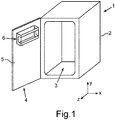
- a household refrigerator 1 is shown in a schematic representation, which is designed for storing and preserving food.
- the household refrigerator 1 can be a refrigerator or a freezer or a combined refrigerator-freezer.
- the household refrigerator 1 comprises a housing 2 in which at least one receiving space 3 for food is formed.
- the household refrigeration appliance 1 comprises a door 4 which is arranged pivotably on the housing 2 and is provided for closing the receiving space 3.
- a door rack 6 is arranged in the exemplary embodiment, only to be understood as an example in terms of number and position.
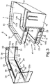
- FIG. 2 an embodiment of a door rack 6 is shown in a perspective view.
- This door rack 6 comprises a base body 7 which, in the embodiment shown, is made in one piece from plastic.
- the base body 7 comprises a rear wall 8 and a base 9 adjoining it.
- the base body 7 furthermore comprises a receiving area 10 in which the food, such as food and drinks, can be introduced.
- the base body 7 considered in itself is therefore already designed to accommodate food.
- the base body 7 also comprises side walls 11 and 12 on opposite sides, which are connected both to the rear wall 8 and to the base 9.
- the base body 7 also has an upper bracket 13 and a lower bracket 14 arranged at a distance from it in the height direction and thus in the y-direction.
- the upper bracket 13 and the lower bracket 14 are each curved here, in particular U-shaped, and, viewed in their longitudinal extension, extend in particular parallel to one another and in horizontal planes.
- the bracket 14 extends from the plane of the bottom 9 upwards.
- the upper bracket 13 comprises opposite bracket sections 13a and 13b, the ends 13c and 13d of which open into a front edge of the side walls 11 and 12.
- the bracket sections 13a and 13b are thus oriented in the direction of the rear wall 8 and end at a distance from the rear wall 8.
- the same is also provided for the lower bracket 14, which has opposite bracket sections 14a and 14b with respective ends 14c and 14d. These ends 14c and 14d also terminate at a front edge, facing away from the rear wall 8, of the side walls 11 and 12.
- the lower bracket 14 is also connected to the base 9, in particular over its entire extension measured along the U-shape or its entire length.
- the upper bracket 13 forms an upper termination of the base body 7 in the height direction (y-direction), whereas the lower bracket 14 forms a lower termination of the base body 7.
- the upper bracket 13 is also shaped like a U in particular over its entire length in a cross section perpendicular to its longitudinal extension.
- this U-shape is formed on an upper edge in this regard, an upper web 16 which extends outward and thus facing away from the receiving space 10.
- a lower web 17 is integrally formed on this middle leg 15, which is also directed outwards and is thus designed to face away from the receiving space 10.
- Both webs 16 and 17 are formed without interruption over the entire length of the upper bracket 13 and thus also over the entire length of the central leg 15.
- These webs 16 and 17 also each form a support web for an additional part, at least in some areas.
- the upper web 16 is widened or enlarged in the area of the bracket section 13a and also in the area of the bracket section 13b, in particular towards the ends 13c and 13d. The same is provided for the lower web 17.
- latching element 18 is formed adjacent to the ends 13c and 13d, wherein in Fig. 2 only one locking element 18 is shown.
- This latching element 18 is an outwardly raised component which, in the embodiment shown, is designed in particular U-shaped, the opening of the U-shape being oriented towards the rear wall 8.
- a vertical centering web 19 is formed, which extends over the entire height of the center leg 15 between the upper web 16 and the lower web 17. This improves centering or securing the position of an additional part attached to the base body 7.
- the lower bracket 14 also has a central leg 20 and an upper web 21 and a lower web 22.
- the webs 21 and 22 are designed without interruptions, in particular over their entire length, and in particular extend over the entire length Length of the lower bracket 14.
- These webs 21 and 22 are also oriented horizontally outward and thus facing away from the receiving space 10, so that the lower bracket 14 is also U-shaped in a section perpendicular to its longitudinal extension.
- the webs 21 and 22 are designed as support webs for an additional part to be fastened to the base body 7, at least in some areas.
- the webs 21 and 22 in the area of the bracket sections 14a and 14b and in particular towards the ends 14c and 14d are designed to widen or widen, as is also the case in FIG Fig. 2 is shown, whereby the largest possible area of contact with a counter-web is achieved at the ends and a mechanical stability of the connection as well as an exact positioning of the components is improved.
- a latching element is also formed here adjacent to the ends 14c and 14d on an outer side of the center leg 20, with FIG Fig. 2 only the locking element 23 can be seen.
- This latching element 23 is also preferably U-shaped and oriented with the opening of the U-shape in the direction of the rear wall 8.
- a corresponding positioning web 24 is also formed here.
- further webs 25, 26, 27 are formed which extend vertically on an outside of the center leg 20 and in particular extend between the upper web 21 and the lower web 22.
- These additional webs 25 to 28 stiffen the base body 7, in particular in the area of the bottom 9 with the lower bracket 14.
- an additional part 28 separate from the base body 7 is then also shown in the embodiment shown there.
- This additional part 28 is also U-shaped and represents a visor, which means that a free space between the brackets 13 and 14 and the brackets 13 and 14 are thereby covered on the front.
- the additional part 28 is designed to be latched on the base body 7, the latching on the upper one here Bracket 13 and the lower bracket 14 is provided.
- the additional part 28 comprises latching elements 30 and 31 on an inner side 29 facing the brackets 13 and 14, and also on the opposite free leg of the U-shape corresponding and in Fig. 2 Another two latching elements, not shown, which then latch into the corresponding latching elements 18 and 23 on the brackets 13 and 14.
- the additional part 28 is at least partially transparent and thus transparent.
- a non-transparent strip 34 or 35 is formed both in the upper region of the additional part 28 and in the lower region of the additional part 28.
- These strips 34 and 35 preferably have a height (extension in the y direction) which corresponds to the height of the brackets 13 and 14. In the mounted state of the additional part 28 on the base body 7, these brackets 13 and 14 are thus completely covered by the strips 34 and 35 when viewed from the outside.
- FIG. 3 is in a further perspective illustration of the door rack 6 according to Fig. 2 shown.
- the receptacles 36 and 37 on the additional part 28, in which the positioning webs 19 and 24 engage, can be seen.
- a further web 39 is formed parallel and at a distance from the counter web 32 on a front element 38 of the additional part 28 on this inner side 29.
- the distance, measured in the height direction and thus in the y direction, between the counter web 32 and the further web 39 is in particular formed such that the lower web 17 of the upper bracket 13 can dip into it.
- this lower web 17 is held from above by the web 39 and from below by the counter web 32 or clamped in between, since the slot or the free space between the web 39 and the counter web 32 enables exchange, in particular precisely fitting immersion.
- a further separate web 40 is formed on the inside 29 at a distance from and parallel to the lower counter web 33.
- the distance, measured in the height direction, between the lower counter-web 33 and the further web 40 is formed such that the upper web 21 of the lower bracket 14 can plunge in with an accurate fit. Due to the design and positioning of the brackets 13 and 14, a free space 41 is formed between these brackets 13 and 14, which is then closed by the additional part 28.
- Fig. 4 is shown in a perspective view of the door racks 6, the additional part 28 being shown here on the base body 7 in the assembled position. It can be seen that the additional part 28 extends over a height which corresponds to the height between the upper web 16 of the upper bracket 13 and the lower web 22 of the lower bracket 14. In addition, the additional part 28 has a length (measured in the xz plane) which corresponds to the length of the upper bracket 13 and also to the length of the lower bracket 14.
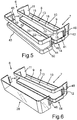
- Fig. 5 an example of a door rack 6 is shown in a perspective illustration.
- the additional part 28 is not formed as a full-surface visor, as shown in FIGS. 2 to 4 is designed, but it is formed from a first clasp 42 and a second clasp 43.
- the two clasps 42 and 43 are designed as curved strips, in particular U-shaped. They each have a height that corresponds to the height of the bracket 13 or the lower one Bracket 14 corresponds.
- the first additional part embodied as a first clasp 42 just completely covers the upper bracket 13 in the assembled state.
- the second additional part designed as a second clasp 43, covers the lower bracket 14 on the outside.
- the two clasps 42 and 43 are connected at their ends with connecting parts 44 and 45, so that the two clasps 42 and 43 are formed in one piece with the connecting elements 44 and 45 and thus a one-piece overall additional part is formed .
- latching elements 46 and 47 are formed on these connecting elements 44 and 45, which latch into latching receptacles on the base body 7, in particular on the side walls 11 and 12, the latching receptacle 48 being shown here as an example.
- Fig. 6 an alternative embodiment of a door rack 6 is shown in an example.
- the additional part 28 is designed differently here.
- the base body 7 is according to the configuration in Fig. 5 educated.
- the additional part 28 is again designed as a visor and here fully transparent.
- the additional part 28 with its one-piece design here again extends over the entire height between the upper web 16 of the upper bracket 13 and the lower web 22 of the lower bracket 14.
- Fig. 7 an embodiment of a door rack 6 is shown in a further perspective illustration.
- two separate additional parts are provided as a first clasp 42 and as a second clasp 43, which are separated here and not, as in FIG Fig. 5 , are designed as a common overall additional part.
- the clasp 42 has a mating flange 49 which, in the assembled state on the upper bracket 13, makes contact with the web 17, which represents a support web.
- the web 17 represents a support web.
- the second clasp 43 also has a corresponding counter-web 50.
- Fig. 8 the mounted state of the clasps 42 and 43 on the base body 7, in particular the upper bracket 13 and the lower bracket 14, is shown.
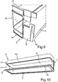
- FIG. 9 Another embodiment of a door rack 6 is shown in a perspective partial representation.
- the base body 7 is not formed in one piece, but rather in several parts and has a base part 6a.
- the upper bracket 13, which here represents a separate component, can be fastened, in particular inserted, to this base part 6a.
- FIG. 10 Another embodiment of a door rack 6 is shown in a perspective view. It can be seen here that the bottom 9 is at least partially transparent. It can be provided that this transparent area is made of glass. It can also be provided that this transparent element is arranged non-destructively detachable on the further base part of the base body 7, so that it can also be correspondingly removed and reinserted.
- an additional part is designed as a clasp 42, which is fastened to the upper bracket 13 and covers it at the front. The lower bracket 14 is also covered by a corresponding clasp 43.
- the free space 41 is then in this embodiment, as in the embodiments according to FIG Fig. 5 and Fig. 8 open and thus also accessible or accessible from the side or from the front as far as the receiving space 10.
- the upper bracket 13 and / or the lower bracket 14 preferably have a height in the height direction (y-direction) which is preferably between 1.5 cm and 5 cm, in particular between 2.5 cm and 4 cm.
- a bracket 13 and / or 14 has this height over its entire longitudinal extent, in particular the height of a bracket 13 and / or 14 is constant over its entire longitudinal extent.
Landscapes
- Engineering & Computer Science (AREA)
- Chemical & Material Sciences (AREA)
- Combustion & Propulsion (AREA)
- Physics & Mathematics (AREA)
- Mechanical Engineering (AREA)
- Thermal Sciences (AREA)
- General Engineering & Computer Science (AREA)
- Refrigerator Housings (AREA)
Claims (10)
- Balconnet (6) pour un appareil frigorifique ménager (1), avec un corps de base (7) formé pour l'accueil de denrées stockées, et avec une pièce additionnelle (28, 42, 43) séparée du corps de base (7), laquelle est fixée au corps de base (7), caractérisé en ce que le corps de base (7) présente un étrier supérieur (13) orienté vers l'avant et éloigné d'une paroi arrière (8) du corps de base (7) et un étrier inférieur (14) orienté vers l'avant, disposé à distance et éloigné de la paroi arrière (8) du corps de base (7), dans lequel la pièce additionnelle séparée (28, 42, 43) est encliquetée à l'étrier supérieur (13) et/ou à l'étrier inférieur (14), et dans lequel l'étrier supérieur (13) présente, en au moins une section d'étrier (13a, 13b) dirigée vers la paroi arrière (8), une âme d'appui (16, 17) s'élargissant en direction d'une extrémité (13c, 13d) de la section d'étrier (13a, 13b) pour le contact d'une contre-âme (32, 49) de la pièce additionnelle séparée (28, 42) et/ou l'étrier inférieur (14) présente, en au moins une section d'étrier (14a, 14b) dirigée vers la paroi arrière (8), une âme d'appui (21, 22) s'élargissant en direction d'une extrémité (14c, 14d) de la section d'étrier (14a, 14b) pour le contact d'une contre-âme (33, 50) de la pièce additionnelle séparée (28, 43), dans lequel soit une première pièce additionnelle est une première agrafe (42) adaptée à la forme et aux dimensions de l'étrier supérieur (13) et fixée à l'étrier supérieur (13), de sorte que seul l'étrier supérieur (13) est couvert côté extérieur par l'agrafe (42) et/ou une deuxième pièce additionnelle est une deuxième agrafe (43) adaptée à la forme et aux dimensions de l'étrier inférieur (14) et fixée à l'étrier inférieur (14), de sorte que seul l'étrier inférieur (14) est couvert côté extérieur par la deuxième agrafe (43), soit la pièce additionnelle (28) est une visière fixée à l'étrier supérieur (13) et à l'étrier inférieur (14) et qui couvre un espace libre (41) entre l'étrier supérieur (13) et l'étrier inférieur (14).
- Balconnet (6) selon la revendication 1, caractérisé en ce que l'étrier supérieur (13) forme une finition frontale supérieure du corps de base (7).
- Balconnet (6) selon la revendication 1 ou 2, caractérisé en ce que l'étrier inférieur (14) forme une finition frontale inférieure du corps de base (7).
- Balconnet (6) selon l'une des revendications précédentes, caractérisé en ce que l'étrier supérieur (13) est formé en forme de U et/ou l'étrier inférieur (14) est formé en forme de U.
- Balconnet (6) selon l'une des revendications précédentes, caractérisé en ce que le corps de base (7) présente un fond (9).
- Balconnet (6) selon l'une des revendications précédentes, caractérisé en ce que le corps de base (7) est fabriqué en une seule pièce.
- Balconnet (6) selon l'une des revendications précédentes, caractérisé en ce que la pièce additionnelle (28, 42, 43) couvre l'étrier supérieur (13) et/ou l'étrier inférieur (14) côté extérieur à pleine surface et/ou de façon opaque.
- Balconnet (6) selon l'une des revendications précédentes, caractérisé en ce que parallèlement à la contre-âme (32, 33), une âme supplémentaire (39, 40) est formée sur le côté intérieur (29) et un espace libre mesuré dans le sens de la hauteur entre la contre-âme (32, 33) et l'âme supplémentaire (39, 40) est formé de telle sorte que l'âme d'appui (16, 17, 21, 22) d'un étrier (13, 14) y plonge, en particulier y plonge de façon sur-mesure.
- Balconnet (6) selon l'une des revendications précédentes, caractérisé en ce que la pièce additionnelle (28, 42, 43), en particulier observée selon son étendue longitudinale, est adaptée au façonnement de l'étrier supérieur (13) et/ou au façonnement de l'étrier inférieur (14), en particulier en étant formée en forme de U.
- Appareil frigorifique ménager (1) avec une carcasse (2) et un espace d'accueil (3) pour denrées alimentaires formé à l'intérieur de celle-ci et obturable par une porte (4), et avec au moins un balconnet (6) selon l'une des revendications précédentes disposé en un côté intérieur (5) de la porte (4).
Priority Applications (1)
| Application Number | Priority Date | Filing Date | Title |
|---|---|---|---|
| PL17159980T PL3228967T3 (pl) | 2016-04-06 | 2017-03-09 | Półka drzwiowa do urządzenia chłodzącego gospodarstwa domowego z odpowiednim korpusem podstawowym i oddzielną od niego częścią dodatkową i urządzenie chłodzące do gospodarstwa domowego |
Applications Claiming Priority (1)
| Application Number | Priority Date | Filing Date | Title |
|---|---|---|---|
| DE102016205705.7A DE102016205705A1 (de) | 2016-04-06 | 2016-04-06 | Türabsteller für ein Haushaltskältegerät mit einem spezifischen Grundkörper und einem dazu separaten Zusatzteil sowie Haushaltskältegerät |
Publications (2)
| Publication Number | Publication Date |
|---|---|
| EP3228967A1 EP3228967A1 (fr) | 2017-10-11 |
| EP3228967B1 true EP3228967B1 (fr) | 2021-01-27 |
Family
ID=58265852
Family Applications (1)
| Application Number | Title | Priority Date | Filing Date |
|---|---|---|---|
| EP17159980.6A Active EP3228967B1 (fr) | 2016-04-06 | 2017-03-09 | Compartiment de porte pour un réfrigérateur ménager comprenant un corps de base spécifique et une partie supplémentaire séparée à celui-ci et réfrigérateur ménager |
Country Status (5)
| Country | Link |
|---|---|
| US (1) | US10113787B2 (fr) |
| EP (1) | EP3228967B1 (fr) |
| CN (2) | CN107270636B (fr) |
| DE (1) | DE102016205705A1 (fr) |
| PL (1) | PL3228967T3 (fr) |
Families Citing this family (4)
| Publication number | Priority date | Publication date | Assignee | Title |
|---|---|---|---|---|
| DE102016225610A1 (de) * | 2016-12-20 | 2018-06-21 | BSH Hausgeräte GmbH | Türabsteller mit einem an einem Grundkörper verrasteten Boden sowie Haushaltskältegerät mit einem Türabsteller |
| DE102018203431A1 (de) * | 2018-03-07 | 2019-09-12 | BSH Hausgeräte GmbH | Kühlgutabstellfach mit L-förmigen Rahmen, Tür sowie Haushaltskältegerät |
| DE102020210128A1 (de) | 2020-08-11 | 2022-02-17 | BSH Hausgeräte GmbH | Lebensmittel-Aufnahmebehälter mit spezifischer optischer Vorrichtung zur Wandstärkendarstellung einer Seitenwand, sowie Haushaltskältegerät |
| US11365930B2 (en) * | 2020-11-06 | 2022-06-21 | Bsh Home Appliances Corporation | Removable door bin height extender for refrigerator |
Family Cites Families (29)
| Publication number | Priority date | Publication date | Assignee | Title |
|---|---|---|---|---|
| JPS62143181U (fr) * | 1986-03-04 | 1987-09-09 | ||
| US5160191A (en) * | 1991-10-18 | 1992-11-03 | White Consolidated Industries, Inc. | Adjustable refrigerator door shelf retainer |
| US5322366A (en) * | 1993-02-04 | 1994-06-21 | Whirlpool Corporation | Interior door shelf support system for refrigerator |
| US5445452A (en) * | 1994-05-23 | 1995-08-29 | Whirlpool Corporation | Refrigerator adjustable utility compartment/sliding shelf |
| US20030020384A1 (en) * | 2001-07-16 | 2003-01-30 | Bush Roger K. | Crisper trim enhancement |
| KR100412947B1 (ko) * | 2001-11-16 | 2003-12-31 | 주식회사 엘지이아이 | 냉장고의 도어 바스켓 |
| US6782710B2 (en) * | 2002-07-16 | 2004-08-31 | Maytag Corporation | Kid's zone compartment assembly for a refrigerator |
| DE102004012497A1 (de) * | 2004-03-15 | 2005-10-06 | BSH Bosch und Siemens Hausgeräte GmbH | Kühlschrank mit Kühlgutabsteller |
| US7228612B2 (en) * | 2004-03-23 | 2007-06-12 | Viking Range Corporation | Methods of making refrigerator storage assemblies |
| US7293846B2 (en) * | 2004-10-15 | 2007-11-13 | Whirlpool Corporation | Storage bin assembly for a refrigerator |
| KR20060036589A (ko) * | 2004-10-26 | 2006-05-02 | 엘지전자 주식회사 | 냉장고 도어바스켓 |
| KR20070013137A (ko) * | 2005-07-25 | 2007-01-30 | 삼성전자주식회사 | 냉장고 |
| CN2833465Y (zh) * | 2005-09-22 | 2006-11-01 | 合肥美菱股份有限公司 | 拼装式冰箱瓶框 |
| KR20070062843A (ko) * | 2005-12-13 | 2007-06-18 | 주식회사 대우일렉트로닉스 | 냉장고의 회전식 포켓 |
| KR100688657B1 (ko) * | 2005-12-30 | 2007-03-02 | 엘지전자 주식회사 | 착탈식 수납코너가 구비된 냉장고 |
| US7651182B2 (en) * | 2006-03-31 | 2010-01-26 | Maytag Corporation | Adjustable retainer assembly for a refrigerator door storage unit |
| DE102007005951A1 (de) * | 2007-02-06 | 2008-08-07 | BSH Bosch und Siemens Hausgeräte GmbH | Butterfach für ein Kältegerät |
| DE102008019261A1 (de) | 2008-04-11 | 2009-10-15 | BSH Bosch und Siemens Hausgeräte GmbH | Haushalts-Kältegerät mit mindestens einem Abstellbehältnis |
| DE202008005350U1 (de) | 2008-04-17 | 2008-07-03 | BSH Bosch und Siemens Hausgeräte GmbH | Abstellbehälter für ein Kältegerät |
| EP2235454B1 (fr) * | 2007-12-31 | 2017-04-05 | Arçelik Anonim Sirketi | Dispositif de refroidissement |
| JP4654277B2 (ja) * | 2008-08-08 | 2011-03-16 | 日立アプライアンス株式会社 | 冷蔵庫 |
| DE102009028784A1 (de) * | 2009-08-21 | 2011-02-24 | BSH Bosch und Siemens Hausgeräte GmbH | Dekorelement für ein Kältegerät |
| DE102010003839A1 (de) | 2010-04-09 | 2011-10-13 | BSH Bosch und Siemens Hausgeräte GmbH | Türabsteller für ein Kältegerät |
| WO2012106316A2 (fr) * | 2011-01-31 | 2012-08-09 | Electrolux Home Products, Inc. | Bac inclinable et bac à légumes amovible |
| EP2498031A1 (fr) * | 2011-03-08 | 2012-09-12 | Electrolux Home Products Corporation N.V. | Appareil de réfrigération |
| US8616665B2 (en) * | 2011-05-24 | 2013-12-31 | Whirlpool Corporation | Door bin for a domestic refrigerator |
| KR101949958B1 (ko) * | 2012-07-31 | 2019-02-21 | 엘지전자 주식회사 | 냉장고 |
| DE102012223118A1 (de) * | 2012-12-13 | 2014-06-18 | BSH Bosch und Siemens Hausgeräte GmbH | Kältegerät mit einem Türabsteller |
| JP6396015B2 (ja) * | 2013-11-28 | 2018-09-26 | 東芝ライフスタイル株式会社 | 冷蔵庫 |
-
2016
- 2016-04-06 DE DE102016205705.7A patent/DE102016205705A1/de active Pending
-
2017
- 2017-03-09 PL PL17159980T patent/PL3228967T3/pl unknown
- 2017-03-09 EP EP17159980.6A patent/EP3228967B1/fr active Active
- 2017-04-06 CN CN201710220369.7A patent/CN107270636B/zh active Active
- 2017-04-06 CN CN202111054236.XA patent/CN113776259B/zh active Active
- 2017-04-06 US US15/480,772 patent/US10113787B2/en active Active
Non-Patent Citations (1)
| Title |
|---|
| None * |
Also Published As
| Publication number | Publication date |
|---|---|
| EP3228967A1 (fr) | 2017-10-11 |
| CN113776259A (zh) | 2021-12-10 |
| CN107270636B (zh) | 2021-08-10 |
| DE102016205705A1 (de) | 2017-10-12 |
| US10113787B2 (en) | 2018-10-30 |
| CN107270636A (zh) | 2017-10-20 |
| PL3228967T3 (pl) | 2021-07-12 |
| CN113776259B (zh) | 2023-06-09 |
| US20170292775A1 (en) | 2017-10-12 |
Similar Documents
| Publication | Publication Date | Title |
|---|---|---|
| EP3228967B1 (fr) | Compartiment de porte pour un réfrigérateur ménager comprenant un corps de base spécifique et une partie supplémentaire séparée à celui-ci et réfrigérateur ménager | |
| WO2011094772A1 (fr) | Système de tiroir | |
| EP1926949B1 (fr) | Carcasse d'appareil ménager | |
| DE102010039618A1 (de) | Kältegerät mit Ablage für Kühlgut | |
| DE102017205089A1 (de) | Haushaltskältegerät mit einer Innenverkleidung mit mehreren separaten Verkleidungswänden sowie Verfahren zum Herstellen eines Haushaltskältegeräts | |
| AT509366A1 (de) | Schubladenbehälter | |
| EP3441704A1 (fr) | Porte d'un appareil frigorifique ménager dotée d'une plaque de recouvrement spécifiquement fixée et appareil frigorifique ménager | |
| EP2844108B1 (fr) | Dispositif de retenue pour un élément support d'une armoire telle qu'un réfrigérateur, un congélateur ou armoire pour conserver du vin | |
| EP3559569B1 (fr) | Balconnet de rangement comportant une tablette encliquetée dans un corps de base, ainsi qu'appareil électroménager frigorifique pourvu d'un balconnet de rangement | |
| EP3537077B1 (fr) | Compartiment de stockage pour produits à réfrigérer pourvu d'un cadre en l, porte ainsi qu'appareil de refroidissement électroménager | |
| DE102016202186A1 (de) | Haushaltsgerätevorrichtung | |
| EP3628945B1 (fr) | Porte pour un appareil électroménager pourvue de panneau décoratif avant et élément de protection pour le bord du panneau décoratif et appareil électroménager | |
| EP3457056A1 (fr) | Compartiment de porte pour un appareil frigorifique | |
| EP2281159B1 (fr) | Porte pour appareil ménager | |
| EP3967958A1 (fr) | Agencement de plaque de rangement pourvu de cadre support doté d'un rail profilé en métal, ainsi qu'une appareil réfrigérateur | |
| WO2014170167A1 (fr) | Réfrigérateur domestique présentant un corps de calage pendant le transport | |
| DE102014223518A1 (de) | Haushaltskältegerät mit einer Lebensmittel-Aufnahmeschale in einem Aufnahmeraum, welche eine Frontwand aus Glas aufweist | |
| EP3546859B1 (fr) | Appareil frigorifique ménager doté d'une étagère en forme de plaque fixée | |
| EP0173810A2 (fr) | Subdivision de rayon avec cloisons enfichables pour tiroirs ou similaires | |
| DE102016006221A1 (de) | Türabsteller | |
| DE102008018233A1 (de) | Kältegerät mit Türabsteller | |
| DE102022202522A1 (de) | Lebensmittel-Aufnahmebehälter mit einer Frontwand mit nutartiger Aufnahme für einen Deckel, sowie Haushaltskältegerät | |
| EP3809079A1 (fr) | Récipient collecteur alimentaire doté d'un rabat pivotant sur la barquette, ainsi que appareil de froid électroménager | |
| EP3885681A1 (fr) | Compartiment de produits réfrigérés pourvu de cadre autoserrant, porte, ainsi qu'appareil frigorifique électroménager | |
| DE202019104971U1 (de) | Schubkastenblende |
Legal Events
| Date | Code | Title | Description |
|---|---|---|---|
| PUAI | Public reference made under article 153(3) epc to a published international application that has entered the european phase |
Free format text: ORIGINAL CODE: 0009012 |
|
| STAA | Information on the status of an ep patent application or granted ep patent |
Free format text: STATUS: THE APPLICATION HAS BEEN PUBLISHED |
|
| AK | Designated contracting states |
Kind code of ref document: A1 Designated state(s): AL AT BE BG CH CY CZ DE DK EE ES FI FR GB GR HR HU IE IS IT LI LT LU LV MC MK MT NL NO PL PT RO RS SE SI SK SM TR |
|
| AX | Request for extension of the european patent |
Extension state: BA ME |
|
| STAA | Information on the status of an ep patent application or granted ep patent |
Free format text: STATUS: REQUEST FOR EXAMINATION WAS MADE |
|
| 17P | Request for examination filed |
Effective date: 20180411 |
|
| RBV | Designated contracting states (corrected) |
Designated state(s): AL AT BE BG CH CY CZ DE DK EE ES FI FR GB GR HR HU IE IS IT LI LT LU LV MC MK MT NL NO PL PT RO RS SE SI SK SM TR |
|
| STAA | Information on the status of an ep patent application or granted ep patent |
Free format text: STATUS: EXAMINATION IS IN PROGRESS |
|
| 17Q | First examination report despatched |
Effective date: 20190830 |
|
| GRAP | Despatch of communication of intention to grant a patent |
Free format text: ORIGINAL CODE: EPIDOSNIGR1 |
|
| STAA | Information on the status of an ep patent application or granted ep patent |
Free format text: STATUS: GRANT OF PATENT IS INTENDED |
|
| INTG | Intention to grant announced |
Effective date: 20200918 |
|
| GRAS | Grant fee paid |
Free format text: ORIGINAL CODE: EPIDOSNIGR3 |
|
| GRAA | (expected) grant |
Free format text: ORIGINAL CODE: 0009210 |
|
| STAA | Information on the status of an ep patent application or granted ep patent |
Free format text: STATUS: THE PATENT HAS BEEN GRANTED |
|
| AK | Designated contracting states |
Kind code of ref document: B1 Designated state(s): AL AT BE BG CH CY CZ DE DK EE ES FI FR GB GR HR HU IE IS IT LI LT LU LV MC MK MT NL NO PL PT RO RS SE SI SK SM TR |
|
| REG | Reference to a national code |
Ref country code: GB Ref legal event code: FG4D Free format text: NOT ENGLISH |
|
| REG | Reference to a national code |
Ref country code: CH Ref legal event code: EP |
|
| REG | Reference to a national code |
Ref country code: AT Ref legal event code: REF Ref document number: 1358723 Country of ref document: AT Kind code of ref document: T Effective date: 20210215 |
|
| REG | Reference to a national code |
Ref country code: IE Ref legal event code: FG4D Free format text: LANGUAGE OF EP DOCUMENT: GERMAN |
|
| REG | Reference to a national code |
Ref country code: DE Ref legal event code: R096 Ref document number: 502017009190 Country of ref document: DE |
|
| REG | Reference to a national code |
Ref country code: NL Ref legal event code: MP Effective date: 20210127 |
|
| REG | Reference to a national code |
Ref country code: LT Ref legal event code: MG9D |
|
| PG25 | Lapsed in a contracting state [announced via postgrant information from national office to epo] |
Ref country code: LT Free format text: LAPSE BECAUSE OF FAILURE TO SUBMIT A TRANSLATION OF THE DESCRIPTION OR TO PAY THE FEE WITHIN THE PRESCRIBED TIME-LIMIT Effective date: 20210127 Ref country code: BG Free format text: LAPSE BECAUSE OF FAILURE TO SUBMIT A TRANSLATION OF THE DESCRIPTION OR TO PAY THE FEE WITHIN THE PRESCRIBED TIME-LIMIT Effective date: 20210427 Ref country code: HR Free format text: LAPSE BECAUSE OF FAILURE TO SUBMIT A TRANSLATION OF THE DESCRIPTION OR TO PAY THE FEE WITHIN THE PRESCRIBED TIME-LIMIT Effective date: 20210127 Ref country code: GR Free format text: LAPSE BECAUSE OF FAILURE TO SUBMIT A TRANSLATION OF THE DESCRIPTION OR TO PAY THE FEE WITHIN THE PRESCRIBED TIME-LIMIT Effective date: 20210428 Ref country code: FI Free format text: LAPSE BECAUSE OF FAILURE TO SUBMIT A TRANSLATION OF THE DESCRIPTION OR TO PAY THE FEE WITHIN THE PRESCRIBED TIME-LIMIT Effective date: 20210127 Ref country code: NO Free format text: LAPSE BECAUSE OF FAILURE TO SUBMIT A TRANSLATION OF THE DESCRIPTION OR TO PAY THE FEE WITHIN THE PRESCRIBED TIME-LIMIT Effective date: 20210427 Ref country code: PT Free format text: LAPSE BECAUSE OF FAILURE TO SUBMIT A TRANSLATION OF THE DESCRIPTION OR TO PAY THE FEE WITHIN THE PRESCRIBED TIME-LIMIT Effective date: 20210527 |
|
| PG25 | Lapsed in a contracting state [announced via postgrant information from national office to epo] |
Ref country code: LV Free format text: LAPSE BECAUSE OF FAILURE TO SUBMIT A TRANSLATION OF THE DESCRIPTION OR TO PAY THE FEE WITHIN THE PRESCRIBED TIME-LIMIT Effective date: 20210127 Ref country code: RS Free format text: LAPSE BECAUSE OF FAILURE TO SUBMIT A TRANSLATION OF THE DESCRIPTION OR TO PAY THE FEE WITHIN THE PRESCRIBED TIME-LIMIT Effective date: 20210127 Ref country code: SE Free format text: LAPSE BECAUSE OF FAILURE TO SUBMIT A TRANSLATION OF THE DESCRIPTION OR TO PAY THE FEE WITHIN THE PRESCRIBED TIME-LIMIT Effective date: 20210127 |
|
| PG25 | Lapsed in a contracting state [announced via postgrant information from national office to epo] |
Ref country code: IS Free format text: LAPSE BECAUSE OF FAILURE TO SUBMIT A TRANSLATION OF THE DESCRIPTION OR TO PAY THE FEE WITHIN THE PRESCRIBED TIME-LIMIT Effective date: 20210527 |
|
| REG | Reference to a national code |
Ref country code: DE Ref legal event code: R097 Ref document number: 502017009190 Country of ref document: DE |
|
| PG25 | Lapsed in a contracting state [announced via postgrant information from national office to epo] |
Ref country code: SM Free format text: LAPSE BECAUSE OF FAILURE TO SUBMIT A TRANSLATION OF THE DESCRIPTION OR TO PAY THE FEE WITHIN THE PRESCRIBED TIME-LIMIT Effective date: 20210127 Ref country code: CZ Free format text: LAPSE BECAUSE OF FAILURE TO SUBMIT A TRANSLATION OF THE DESCRIPTION OR TO PAY THE FEE WITHIN THE PRESCRIBED TIME-LIMIT Effective date: 20210127 Ref country code: EE Free format text: LAPSE BECAUSE OF FAILURE TO SUBMIT A TRANSLATION OF THE DESCRIPTION OR TO PAY THE FEE WITHIN THE PRESCRIBED TIME-LIMIT Effective date: 20210127 Ref country code: MC Free format text: LAPSE BECAUSE OF FAILURE TO SUBMIT A TRANSLATION OF THE DESCRIPTION OR TO PAY THE FEE WITHIN THE PRESCRIBED TIME-LIMIT Effective date: 20210127 |
|
| REG | Reference to a national code |
Ref country code: CH Ref legal event code: PL |
|
| PG25 | Lapsed in a contracting state [announced via postgrant information from national office to epo] |
Ref country code: DK Free format text: LAPSE BECAUSE OF FAILURE TO SUBMIT A TRANSLATION OF THE DESCRIPTION OR TO PAY THE FEE WITHIN THE PRESCRIBED TIME-LIMIT Effective date: 20210127 Ref country code: RO Free format text: LAPSE BECAUSE OF FAILURE TO SUBMIT A TRANSLATION OF THE DESCRIPTION OR TO PAY THE FEE WITHIN THE PRESCRIBED TIME-LIMIT Effective date: 20210127 Ref country code: SK Free format text: LAPSE BECAUSE OF FAILURE TO SUBMIT A TRANSLATION OF THE DESCRIPTION OR TO PAY THE FEE WITHIN THE PRESCRIBED TIME-LIMIT Effective date: 20210127 |
|
| PLBE | No opposition filed within time limit |
Free format text: ORIGINAL CODE: 0009261 |
|
| STAA | Information on the status of an ep patent application or granted ep patent |
Free format text: STATUS: NO OPPOSITION FILED WITHIN TIME LIMIT |
|
| REG | Reference to a national code |
Ref country code: BE Ref legal event code: MM Effective date: 20210331 |
|
| GBPC | Gb: european patent ceased through non-payment of renewal fee |
Effective date: 20210427 |
|
| 26N | No opposition filed |
Effective date: 20211028 |
|
| PG25 | Lapsed in a contracting state [announced via postgrant information from national office to epo] |
Ref country code: ES Free format text: LAPSE BECAUSE OF FAILURE TO SUBMIT A TRANSLATION OF THE DESCRIPTION OR TO PAY THE FEE WITHIN THE PRESCRIBED TIME-LIMIT Effective date: 20210127 Ref country code: IE Free format text: LAPSE BECAUSE OF NON-PAYMENT OF DUE FEES Effective date: 20210309 Ref country code: FR Free format text: LAPSE BECAUSE OF NON-PAYMENT OF DUE FEES Effective date: 20210327 Ref country code: GB Free format text: LAPSE BECAUSE OF NON-PAYMENT OF DUE FEES Effective date: 20210427 Ref country code: LI Free format text: LAPSE BECAUSE OF NON-PAYMENT OF DUE FEES Effective date: 20210331 Ref country code: LU Free format text: LAPSE BECAUSE OF NON-PAYMENT OF DUE FEES Effective date: 20210309 Ref country code: CH Free format text: LAPSE BECAUSE OF NON-PAYMENT OF DUE FEES Effective date: 20210331 Ref country code: AL Free format text: LAPSE BECAUSE OF FAILURE TO SUBMIT A TRANSLATION OF THE DESCRIPTION OR TO PAY THE FEE WITHIN THE PRESCRIBED TIME-LIMIT Effective date: 20210127 |
|
| PG25 | Lapsed in a contracting state [announced via postgrant information from national office to epo] |
Ref country code: SI Free format text: LAPSE BECAUSE OF FAILURE TO SUBMIT A TRANSLATION OF THE DESCRIPTION OR TO PAY THE FEE WITHIN THE PRESCRIBED TIME-LIMIT Effective date: 20210127 |
|
| PG25 | Lapsed in a contracting state [announced via postgrant information from national office to epo] |
Ref country code: IS Free format text: LAPSE BECAUSE OF FAILURE TO SUBMIT A TRANSLATION OF THE DESCRIPTION OR TO PAY THE FEE WITHIN THE PRESCRIBED TIME-LIMIT Effective date: 20210527 |
|
| PG25 | Lapsed in a contracting state [announced via postgrant information from national office to epo] |
Ref country code: BE Free format text: LAPSE BECAUSE OF NON-PAYMENT OF DUE FEES Effective date: 20210331 |
|
| REG | Reference to a national code |
Ref country code: AT Ref legal event code: MM01 Ref document number: 1358723 Country of ref document: AT Kind code of ref document: T Effective date: 20220309 |
|
| PG25 | Lapsed in a contracting state [announced via postgrant information from national office to epo] |
Ref country code: HU Free format text: LAPSE BECAUSE OF FAILURE TO SUBMIT A TRANSLATION OF THE DESCRIPTION OR TO PAY THE FEE WITHIN THE PRESCRIBED TIME-LIMIT; INVALID AB INITIO Effective date: 20170309 |
|
| PGFP | Annual fee paid to national office [announced via postgrant information from national office to epo] |
Ref country code: TR Payment date: 20230308 Year of fee payment: 7 Ref country code: PL Payment date: 20230224 Year of fee payment: 7 Ref country code: DE Payment date: 20230331 Year of fee payment: 7 |
|
| PG25 | Lapsed in a contracting state [announced via postgrant information from national office to epo] |
Ref country code: NL Free format text: LAPSE BECAUSE OF NON-PAYMENT OF DUE FEES Effective date: 20210127 Ref country code: CY Free format text: LAPSE BECAUSE OF FAILURE TO SUBMIT A TRANSLATION OF THE DESCRIPTION OR TO PAY THE FEE WITHIN THE PRESCRIBED TIME-LIMIT Effective date: 20210127 |
|
| PG25 | Lapsed in a contracting state [announced via postgrant information from national office to epo] |
Ref country code: AT Free format text: LAPSE BECAUSE OF NON-PAYMENT OF DUE FEES Effective date: 20220309 |
|
| PGFP | Annual fee paid to national office [announced via postgrant information from national office to epo] |
Ref country code: IT Payment date: 20230331 Year of fee payment: 7 |
|
| PG25 | Lapsed in a contracting state [announced via postgrant information from national office to epo] |
Ref country code: MK Free format text: LAPSE BECAUSE OF FAILURE TO SUBMIT A TRANSLATION OF THE DESCRIPTION OR TO PAY THE FEE WITHIN THE PRESCRIBED TIME-LIMIT Effective date: 20210127 |