EP3223082A2 - Entwicklungsvorrichtung und bilderzeugungseinrichtung - Google Patents
Entwicklungsvorrichtung und bilderzeugungseinrichtung Download PDFInfo
- Publication number
- EP3223082A2 EP3223082A2 EP17162296.2A EP17162296A EP3223082A2 EP 3223082 A2 EP3223082 A2 EP 3223082A2 EP 17162296 A EP17162296 A EP 17162296A EP 3223082 A2 EP3223082 A2 EP 3223082A2
- Authority
- EP
- European Patent Office
- Prior art keywords
- developing
- shaft
- hole
- end supporting
- supporting member
- Prior art date
- Legal status (The legal status is an assumption and is not a legal conclusion. Google has not performed a legal analysis and makes no representation as to the accuracy of the status listed.)
- Granted
Links
Images









Classifications
-
- G—PHYSICS
- G03—PHOTOGRAPHY; CINEMATOGRAPHY; ANALOGOUS TECHNIQUES USING WAVES OTHER THAN OPTICAL WAVES; ELECTROGRAPHY; HOLOGRAPHY
- G03G—ELECTROGRAPHY; ELECTROPHOTOGRAPHY; MAGNETOGRAPHY
- G03G15/00—Apparatus for electrographic processes using a charge pattern
- G03G15/06—Apparatus for electrographic processes using a charge pattern for developing
- G03G15/08—Apparatus for electrographic processes using a charge pattern for developing using a solid developer, e.g. powder developer
- G03G15/0806—Apparatus for electrographic processes using a charge pattern for developing using a solid developer, e.g. powder developer on a donor element, e.g. belt, roller
- G03G15/0813—Apparatus for electrographic processes using a charge pattern for developing using a solid developer, e.g. powder developer on a donor element, e.g. belt, roller characterised by means in the developing zone having an interaction with the image carrying member, e.g. distance holders
-
- G—PHYSICS
- G03—PHOTOGRAPHY; CINEMATOGRAPHY; ANALOGOUS TECHNIQUES USING WAVES OTHER THAN OPTICAL WAVES; ELECTROGRAPHY; HOLOGRAPHY
- G03G—ELECTROGRAPHY; ELECTROPHOTOGRAPHY; MAGNETOGRAPHY
- G03G15/00—Apparatus for electrographic processes using a charge pattern
- G03G15/06—Apparatus for electrographic processes using a charge pattern for developing
- G03G15/08—Apparatus for electrographic processes using a charge pattern for developing using a solid developer, e.g. powder developer
- G03G15/0896—Arrangements or disposition of the complete developer unit or parts thereof not provided for by groups G03G15/08 - G03G15/0894
-
- G—PHYSICS
- G03—PHOTOGRAPHY; CINEMATOGRAPHY; ANALOGOUS TECHNIQUES USING WAVES OTHER THAN OPTICAL WAVES; ELECTROGRAPHY; HOLOGRAPHY
- G03G—ELECTROGRAPHY; ELECTROPHOTOGRAPHY; MAGNETOGRAPHY
- G03G21/00—Arrangements not provided for by groups G03G13/00 - G03G19/00, e.g. cleaning, elimination of residual charge
- G03G21/16—Mechanical means for facilitating the maintenance of the apparatus, e.g. modular arrangements
- G03G21/18—Mechanical means for facilitating the maintenance of the apparatus, e.g. modular arrangements using a processing cartridge, whereby the process cartridge comprises at least two image processing means in a single unit
- G03G21/1803—Arrangements or disposition of the complete process cartridge or parts thereof
- G03G21/1817—Arrangements or disposition of the complete process cartridge or parts thereof having a submodular arrangement
- G03G21/1825—Pivotable subunit connection
Definitions
- the present invention relates to an image forming apparatus using an electrophotographic image forming system (an electrophotographic process) and a developing device used in an image forming apparatus.
- the image forming apparatus forms an image on a recording material (a recording medium) using the electrophotographic process.
- Examples of the image forming apparatus include a printer (a laser beam printer or a light-emitting diode (LED) printer), a copying machine, a facsimile apparatus, a word processor, and a multifunction peripheral (a multifunction printer) including these apparatuses.
- the developing device is a device for developing, using a developer, an electrostatic latent image formed on an electrophotographic photosensitive drum (hereinafter referred to as a "photosensitive member") as an image bearing member.
- the developing device includes a developing unit, a developing frame member for supporting the developing unit, and components related to the developing unit. Examples of the developing unit include a developing roller as a developer bearing member and a developing blade as a developer regulating member.
- the image forming apparatus such as a printer, using the electrophotographic process uniformly charges the photosensitive member. Then, the image forming apparatus selectively exposes the charged photosensitive member to form an electrostatic latent image on the photosensitive member. Then, using toner as a developer, the image forming apparatus visualizes as a toner image the electrostatic latent image formed on the photosensitive member. Then, the image forming apparatus transfers the toner image formed on the photosensitive member onto a recording material, such as a recording sheet and a plastic sheet, and applies heat and pressure to the toner image transferred onto the recording material to fix the toner image to the recording material, so that the image is recorded.
- a recording material such as a recording sheet and a plastic sheet
- Such an image forming apparatus requires maintenance of various process units used for the electrophotographic process.
- the process units include a charging unit for acting on a photosensitive member, a developing unit, and a cleaning unit.
- a method for integrating the photosensitive member, the charging unit, the developing unit, and the cleaning unit into a cartridge to be attachable to and detachable from the main body of an image forming apparatus is put to practical use. According to this cartridge method, it is possible to provide an image forming apparatus excellent in usability.
- a developing cartridge including a developing unit pivotably supporting a developing roller, and a frame pivotably supporting both end portions of the developing unit.
- the frame is positioned relative to the main body of an image forming apparatus so that the developing unit can pivot, and the developing roller can abut a photosensitive drum and be separate from the photosensitive drum.
- a developing device as specified in claims 1 to 13.
- a developing device as specified in clams 14 to 18.
- a developing device as specified in clams 19 to 22.
- an image forming apparatus as specified in clam 23.
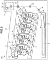
- FIG. 2 the overall configuration of an apparatus main body 100 of an electrophotographic image forming apparatus (hereinafter referred to as an "image forming apparatus") is described.
- an apparatus main body 100 to the apparatus main body 100, four photosensitive drum cartridges (hereinafter referred to as “drum cartridges”) 9 (9Y, 9M, 9C, 9K) are attached, which include photosensitive drums as image bearing members and are attachable to and detachable from the apparatus main body 100.
- drum cartridges which include photosensitive drums as image bearing members and are attachable to and detachable from the apparatus main body 100.
- developing cartridges hereinafter referred to as “developing cartridges”
- the drum cartridges 9 and the developing cartridges 4 are detachably attached to the apparatus main body 100 by attachment members (not illustrated). Further, the drum cartridges 9 and the developing cartridges 4 are provided side by side in the apparatus main body 100 so as to be inclined with respect to the horizontal direction.
- Each drum cartridge 9 includes a photosensitive drum 1 (1a, 1b, 1c, 1d).
- process units such as a charging roller 2 (2a, 2b, 2c, 2d) as a charging member and a cleaning member 6 (6a, 6b, 6c, 6d) as a cleaning member are placed in an integrated manner.
- Each developing cartridge 4 (4Y, 4M, 4C, 4K) includes a developing roller 25 (25a, 25b, 25c, 25d) as a developer bearing member.
- Process units such as a developing blade 35 (35a, 35b, 35c, 35d) as a developer regulating member are placed in an integrated manner.
- the charging roller 2 uniformly charges the surface of the photosensitive drum 1.
- the developing roller 25 abuts the photosensitive drum 1 and develops an electrostatic latent image formed on the photosensitive drum 1, using a developer (hereinafter referred to as "toner"), so that the electrostatic latent image is visualized as a toner image.
- the cleaning member 6 removes the toner remaining on the photosensitive drum 1 after the toner image formed on the photosensitive drum 1 is transferred onto a recording medium S.
- a scanner unit 3 is provided, which is an exposure device for selectively exposing the photosensitive drums 1 based on image information, to form electrostatic latent images on the photosensitive drums 1.
- a cassette 17, which stores recording media S is attached to a lower portion of the apparatus main body 100.
- a recording medium conveying unit is provided to convey the recording media S to an upper portion of the apparatus main body 100 through a secondary transfer roller 69 and a fixing unit 74. That is, a feed roller 54, a conveying roller pair 76, and a registration roller pair 55 are provided.
- the feed roller 54 separates the recording media S in the cassette 17 and feeds the recording media S one by one.
- the conveying roller pair 76 conveys the fed recording medium S.
- the registration roller pair 55 synchronizes the recording medium S with electrostatic latent images formed on the photosensitive drums 1.
- an intermediate transfer unit 5 is provided as an intermediate transfer means for transferring toner images formed on the respective photosensitive drums 1 (1a, 1b, 1c, 1d).
- the intermediate transfer unit 5 includes a driving roller 56, a driven roller 57, primary transfer rollers 58 (58a, 58b, 58c, 58d) at positions opposed to the photosensitive drums 1 of the respective colors, and an opposed roller 59 at a position opposed to the secondary transfer roller 69.
- a transfer belt 14 as an intermediate transfer member is stretched around these rollers. The transfer belt 14 circularly moves in the direction of arrow E so as to be opposed to and in contact with all the photosensitive drums 1.
- Voltage is applied to the primary transfer rollers 58 (58a, 58b, 58c, 58d), so that the toner images are primarily transferred from the photosensitive drums 1 onto the transfer belt 14. Then, voltage is applied to the opposed roller 59, which is placed within the transfer belt 14, and the secondary transfer roller 69, so that the toner on the transfer belt 14 is transferred onto a recording medium S.
- the photosensitive drums 1 are rotated, and the scanner unit 3 selectively exposes the photosensitive drums 1 uniformly charged by the charging rollers 2. Consequently, electrostatic latent images are formed on the photosensitive drums 1 and developed by the developing rollers 25. Toner images of the respective colors are thus formed on the photosensitive drums 1.
- the registration roller pair 55 convey a recording medium S to a secondary transfer position where the opposed roller 59 and the secondary transfer roller 69 abut each other through the transfer belt 14. Then, transfer bias voltage is applied to the secondary transfer roller 69, so that the toner images of the respective colors on the transfer belt 14 are secondarily transferred onto the recording medium S. A color image is thus formed on the recording medium S.
- the recording medium S on which the color image is formed is heated and pressurized by the fixing unit 74, so that the toner image is fixed. Then, the recording medium S is discharged to a discharge portion 75 by discharge rollers 72.
- the fixing unit 74 is provided in an upper portion of the apparatus main body 100.
- a unit biasing members 80 (80a, 80b, 80c, 80d) are provided in the apparatus main body 100 to cause the developing roller 25, which is held in the developing cartridge 4, to abut the photosensitive drum 1.
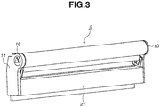
- FIG. 3 is a diagram illustrating the configuration of the drum cartridge 9 (9Y, 9M, 9C, 9K).
- the drum cartridges 9Y, 9M, 9C, and 9K have the same configuration.
- the upstream side in the insertion direction of the drum cartridge 9 and the developing cartridge 4 is defined as a near side
- the downstream side in the insertion direction of the drum cartridge 9 and the developing cartridge 4 is defined as a far side.
- a photosensitive drum 1 is rotatably provided through a drum front bearing 10 and a drum rear bearing 11. On one end side in the axis direction of the photosensitive drum 1, a drum coupling 16 and a flange are provided.
- Fig. 4 is a cross-sectional view of the drum cartridge 9.
- the cleaning member 6 includes a rubber blade 7 and a cleaning supporting member 8.
- An extremity portion 7a of the rubber blade 7 is disposed to abut the photosensitive drum 1 in a direction counter to the rotational direction of the photosensitive drum 1. Residual toner removed from the surface of the photosensitive drum 1 by the cleaning member 6 falls into a removed toner chamber 27a. Further, a sealing sheet 21, which prevents removed toner in the removed toner chamber 27a from leaking, abuts the photosensitive drum 1.
- the driving force of a main body driving motor which is a driving source (not illustrated), is transmitted to the drum coupling 16 of the drum cartridge 9, thereby driving the photosensitive drum 1 to rotate according to an image forming operation.
- the charging roller 2 is rotatably attached to the drum cartridge 9 through a charging roller bearing 28.
- the charging roller 2 is urged (or pressurized) toward the photosensitive drum 1 by a charging roller urging (pressure) member 33 and driven to rotate by the photosensitive drum 1.
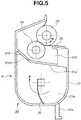
- FIG. 5 is a cross-sectional view of the developing cartridge 4 (4Y, 4M, 4C, 4K), which stores toner.
- the developing cartridge 4Y which stores yellow toner
- the developing cartridge 4M which stores magenta toner
- the developing cartridge 4C which stores cyan toner
- the developing cartridge 4K which stores black toner
- a part of the configuration of each developing cartridge 4 may be different.
- the developing cartridge 4 includes a developing unit 39, which includes the developing roller 25 and a developing frame member 31.
- the developing frame member 31 rotatably supports the developing roller 25, which rotates in the direction of arrow B in contact with the photosensitive drum 1. Further, the developing frame member 31 includes a toner supply roller 34, which rotates in contact with the developing roller 25, and a developing blade 35, which regulates a toner layer on the developing roller 25.
- the developing frame member 31 includes a developing chamber 31c, in which the developing roller 25 is placed, and a toner storage chamber 31a, which is provided below the developing chamber 31c.
- the developing chamber 31c and the toner storage chamber 31a are partitioned by a partition wall 31d.
- an opening 31b is provided so that when toner is conveyed from the toner storage chamber 31a to the developing chamber 31c, the toner passes through the opening 31b.
- a biased portion 31e is provided, which is biased by the unit biasing member 80 (80a, 80b, 80c, 80d) (see Fig. 2 ) of the apparatus main body 100.
- the developing roller 25 and the toner supply roller 34 are rotatably supported by the developing frame member 31 through a developing unit rear bearing 12 and a developing unit front bearing 13, which are provided on both sides in the axis direction of the developing roller 25 (see Fig. 7 ).
- a toner conveying member 36 is provided, which rotates in the direction of arrow N in Fig. 5 to agitate toner stored in the toner storage chamber 31a and also convey the toner to the developing chamber 31c through the opening 31b.
- the rotation center of the toner conveying member 36 is located further on the lower side in the direction of gravity than an opening lower side portion 31b1, which is on the lower side in the direction of gravity of the opening 31b, and the center of the developing roller 25 is located further on the upper side in the direction of gravity than the opening lower side portion 31b1.
- the toner conveying member 36 scoops up toner from the toner storage chamber 31a, which is provided below the developing chamber 31c.
- the toner conveying member 36 supplies the toner to the developing chamber 31c.
- an attachment opening 101 (101a, 101b, 101c, 101d) is provided, to which each drum cartridge 9 and each developing cartridge 4 are attached.
- the drum cartridge 9 is attached to and detached from the attachment opening 101 such that the attachment/detachment direction of the drum cartridge 9 is the axis direction of the photosensitive drum 1.
- the developing cartridge 4 is attached to and detached from the attachment opening 101 such that the attachment/detachment direction of the developing cartridge 4 is the axis direction of the developing roller 25.
- the drum cartridge 9 and the developing cartridge 4 are configured to be inserted from the near side to the far side. In the following description, this direction is referred to as an "insertion direction F". Further, as illustrated in Fig. 6 , the drum cartridge 9 and the developing cartridge 4 are each independently attachable to and detachable from the apparatus main body 100. That is, the developing cartridge 4 is attachable to and detachable from the apparatus main body 100 including the photosensitive drum 1 on which a latent image is to be developed by the developing roller 25. Further, the developing cartridge 4 is attachable to and detachable from the apparatus main body 100 in the state where the drum cartridge 9 including the photosensitive drum 1 on which a latent image is to be developed by the developing roller 25 is attached to the apparatus main body 100.
- a drum cartridge upper guide portion 103 (103a, 103b, 103c, 103d), which is a third main body guide portion, is provided on the upper side of the apparatus main body 100.
- a drum cartridge lower guide portion 102 (102a, 102b, 102c, 102d), which is a fourth main body guide portion, is provided on the lower side of the apparatus main body 100.
- the drum cartridge upper guide portion 103 and the drum cartridge lower guide portion 102 each extend along the insertion direction F of the drum cartridge 9.
- a developing cartridge upper guide portion 105 (105a, 105b, 105c, 105d), which is a first main body guide portion, is provided on the upper side of the apparatus main body 100.
- a developing cartridge lower guide portion 104 (104a, 104b, 104c, 104d), which is a second main body guide portion, is provided on the lower side of the apparatus main body 100.
- the developing cartridge upper guide portion 105 and the developing cartridge lower guide portion 104 each extend along the insertion direction F of the developing cartridge 4.
- the drum cartridge 9 When the drum cartridge 9 is inserted, the drum cartridge 9 is placed on the near side, in the attachment direction, of the drum cartridge lower guide portion 102 and the drum cartridge upper guide portion 103. Then, the drum cartridge 9 is moved in the insertion direction F along the drum cartridge upper guide portion 103 and the drum cartridge lower guide portion 102, to be inserted into the apparatus main body 100.
- the developing cartridge 4 is inserted similarly to the drum cartridge 9.
- the developing cartridge 4 is placed on the near side, in the attachment direction, of the developing cartridge upper guide portion 105 and the developing cartridge lower guide portion 104. Then, the developing cartridge 4 is moved in the insertion direction F along the developing cartridge upper guide portion 105 and the developing cartridge lower guide portion 104, to be inserted into the apparatus main body 100.
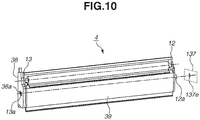
- an end supporting member (first end supporting member) 38 is provided, which pivotably supports an end portion of the developing unit 39 on one end side in the axis direction of the developing roller 25.
- an other-end supporting member (second end supporting member) 37 is provided, which pivotably supports an end portion of the developing unit 39 on the other end side in the axis direction of the developing roller 25 (an end portion on the opposite side of the end portion for which the end supporting member 38 is provided). That is, the end supporting member 38 and the other-end supporting member 37 are provided on both end sides of the developing unit 39 with the developing unit 39 placed between the end supporting member 38 and the other-end supporting member 37.
- a second hole 37a is provided as a positioning hole for pivotably supporting the developing unit 39 and regulating the position of the developing unit 39 in a direction intersecting the axis of the developing roller 25.
- a first hole 38a is provided as a supporting hole for pivotably supporting the developing unit 39 and supporting the developing unit 39 in a manner such that the developing unit 39 is movable in the direction intersecting (desirably a direction orthogonal to) the axis of the developing roller 25.
- a boss 13a (which corresponds to a first shaft) is provided as a supporting shaft pivotably supported by the first hole 38a.
- a boss 12a (which corresponds to a second shaft) is provided as a positioning shaft pivotably supported by the second hole 37a.
- the bosses 12a and 13a have cylindrical shapes. In the present exemplary embodiment, the bosses 12a and 13a are concentric with each other and provided parallel to the axis of the developing roller 25.
- the first hole 38a and the boss 13a are engaged with each other, and the second hole 37a and the boss 12a are engaged with each other. Then, the end supporting member 38 and the other-end supporting member 37 are pivotable relative to the developing unit 39 about the boss 13a and the boss 12a pivotably supported by the first hole 38a and the second hole 37a, respectively. Further, the end supporting member 38 and the other-end supporting member 37 are each independently movable (pivotable) relative to the developing unit 39.
- the end supporting member 38 is configured to support the end portion of the developing unit 39 on one end side in the axis direction of the developing roller 25 and configured not to support the end portion of the developing unit 39 on the other end side in the axis direction of the developing roller 25.
- the other-end supporting member 37 is configured to support the end portion of the developing unit 39 on the other end side in the axis direction of the developing roller 25 and configured not to support the end portion of the developing unit 39 on one end side in the axis direction of the developing roller 25. That is, the other-end supporting member 37 is pivotable relative to the developing unit 39 and the end supporting member 38. The end supporting member 38 is pivotable relative to the developing unit 39 and the other-end supporting member 37.
- the end supporting member 38 can stop its movement relative to the developing unit 39 and the other-end supporting member 37. Further, when the end supporting member 38 pivots relative to the developing unit 39, the other-end supporting member 37 can stop its movement relative to the developing unit 39 and the end supporting member 38.
- the second hole 37a has a circular hole shape. That is, the boss 12a is a positioning portion pivotably supported by the second hole 37a and restrained from moving in the direction intersecting the axis of the developing roller 25.
- the first hole 38a pivotably supports the boss 13a and is formed into a long hole to enable the boss 13a to move in a direction intersecting the axis of the developing roller 25. That is, the first hole 38a is a long hole having a first regulation portion 38a1, which regulates the diameter direction of the boss 13a, and a second regulation portion 38a2, which intersects the first regulation portion 38a1 and is larger than the first regulation portion 38a1. As described above, the first hole 38a is a long hole and thereby can absorb the influence of the shifting of the axis of the developing roller 25 and the centers of the bosses 13a and 12a due to a dimensional tolerance and the like. In the present exemplary embodiment, the first hole 38a has a long circular hole shape. The hole shape of the first hole 38a, however, is not limited to a long circular hole. Alternatively, the hole shape of the first hole 38a may be an angular hole.
- Fig. 15A is a diagram illustrating the state where the first hole 38a and the boss 13a are engaged with each other
- Fig. 15B is a diagram illustrating the state where the second hole 37a and the boss 12a are engaged with each other, each diagram viewed from the axis direction of the developing roller 25.
- the direction in which the boss 13a is restrained by the first regulation portion 38a1 of the first hole 38a from moving in a direction intersecting (desirably orthogonal to) the axis of the developing roller 25 is defined as a first direction V1.
- a direction intersecting (desirably orthogonal to) the axis of the developing roller 25 and also orthogonal to the first direction V1 (a direction toward the second regulation portion 38a2) is defined as a second direction V2.
- the first hole 38a which is a long hole, allows the boss 13a to move in the second direction V2.
- the second hole 37a which is a circular hole, restrains the boss 12a from moving in the first direction V1 and the second direction V2. At least in the second direction V2, a distance D2 by which the boss 13a can move in the first hole 38a is longer than the distance by which the boss 12a can move in the second hole 37a.
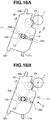
- Figs. 16A and 16B are diagrams illustrating the configuration of the first hole 38a according to the present exemplary embodiment.
- Figs. 16A and 16B illustrate the developing cartridge 4 when viewed from the axis direction of the developing roller 25 in the state where the developing cartridge 4 is attached to the image forming apparatus.
- the direction in which the first hole 38a according to the present exemplary embodiment allows the boss 13a to move is defined as L1.
- a circle having the same center as the center of the photosensitive drum 1 and passing through the center of the first hole 38a is defined as L2.
- a line connecting the center of the photosensitive drum 1 and the center of the first hole 38a is defined as L3.
- L1 intersects L2.
- L1 is inclined with respect to L3.
- the direction of L1 is not limited to a direction as illustrated in Fig. 16A .
- the configuration can also be such that as illustrated in Fig. 16B , L1 is the horizontal direction in the state where the developing cartridge 4 is attached to the image forming apparatus.
- the first hole 38a and the boss 13a are engaged with each other, and the second hole 37a and the boss 12a are engaged with each other.
- the first hole 38a allows the boss 13a to move in a direction intersecting the axis direction of the developing roller 25. Consequently, the developing unit 39 is pivotably supported by the end supporting member 38 and allowed to move in the direction intersecting the axis direction of the developing roller 25.
- the second hole 37a restrains the boss 12a from moving in the direction intersecting the axis direction of the developing roller 25. Consequently, the developing unit 39 is pivotably supported by the other-end supporting member 37 and restrained from moving in the direction intersecting the axis direction of the developing roller 25.
- the developing unit 39 pivots about the boss 12a and the boss 13a relative to the end supporting member 38 and the other-end supporting member 37, respectively.
- a third engaged portion 37b and a fourth engaged portion 37c are provided in the other-end supporting member 37.
- the third engaged portion 37b and the fourth engaged portion 37c are engaged with a third main body engagement portion 98a and a fourth main body engagement portion 98b, respectively, which are provided in the apparatus main body 100. Consequently, the other-end supporting member 37 is positioned relative to the apparatus main body 100.
- a third guided portion 37d and a fourth guided portion 37e are provided, which are guided by the developing cartridge upper guide portion 105 and the developing cartridge lower guide portion 104, respectively, when the developing cartridge 4 is attached (see Fig. 7 ).
- a first engaged portion 38b and a second engaged portion 38c are provided in the end supporting member 38.
- the first engaged portion 38b and the second engaged portion 38c are engaged with a first main body engagement portion 99a and a second main body engagement portion 104e, respectively, which are provided in the apparatus main body 100. Consequently, the end supporting member 38 is positioned relative to the apparatus main body 100.
- the second main body engagement portion 104e and the developing cartridge lower guide portion 104 are the same component. Further, the first engaged portion 38b and the second engaged portion 38c function also as a first guided portion and a second guided portion which are portions guided by the developing cartridge upper guide portion 105 and the developing cartridge lower guide portion 104, respectively.
- the second hole 37a and the first hole 38a are provided in a direction intersecting the axis of the developing roller 25 and overlap each other. That is, the first hole 38a and the second hole 37a are placed to overlap each other when viewed from the axis direction of the developing roller 25.
- the center of the first hole 38a coincides with the center of the second hole 37a (see Fig. 8 ).
- the bosses 12a and 13a are concentric with each other and provided parallel to the axis of the developing roller 25.
- the axis of the developing roller 25 is parallel to the axis of the photosensitive drum 1.
- the bosses 12a and 13a both form the pivotal centers of the developing unit 39.
- the developing unit 39 pivots about the bosses 12a and 13a, so that the developing roller 25 abuts the photosensitive drum 1.
- the boss 12a, the boss 13a, the second hole 37a, and the first hole 38a are provided at positions where moments are generated by the weight of the developing unit 39 itself in the direction in which the developing roller 25 abuts the photosensitive drum 1.
- the developing roller 25 of the developing cartridge 4 abuts the photosensitive drum 1 and visualizes the image.
- the biased portion 31e (which corresponds to a force reception portion) of the developing frame member 31 is biased in a developing unit biasing direction A by the unit biasing member 80 (which corresponds to a force imparting portion) of the apparatus main body 100 (see Fig. 2 ), so that the developing roller 25 abuts the photosensitive drum 1. That is, the biased portion 31e is provided so that when the biased portion 31e is biased by the unit biasing member 80, the developing roller 25 moves in the direction in which the developing roller 25 abuts the photosensitive drum 1.
- Fig. 17 illustrates the structure of the unit biasing member 80.
- Fig. 17 is a diagram illustrating the developing cartridge 4 as viewed from the axis direction of the developing roller 25.
- the developing unit 39 On the far side of the plane of the paper, the developing unit 39 is located.
- the end supporting member 38 On the near side of the plane of the paper, the end supporting member 38 is located.
- the biased portion 31e of the developing frame member 31 is biased by the unit biasing member 80 in a developing unit biasing direction A1 (the same as the direction A).
- the developing unit 39 pivots in a direction R1, and the developing roller 25 abuts the photosensitive drum 1.
- the developing unit pivots in a direction R2and the developing roller 25 separates from the photosensitive drum 1.
- the biased portion 31e is placed such that the distance from the center of the developing roller 25 to the biased portion 31e is longer than the distance from the center of the developing roller 25 to the center of the boss 13a. Further, in the present exemplary embodiment, when a straight line Q1 connecting the center of the developing roller 25 and the center of the boss 13a and a straight line Q2 orthogonal to the straight line Q1 are drawn through the center of the boss 13a, the biased portion 31e is placed in an area on the opposite side of the developing roller 25 with respect to the straight line Q2.
- the developing roller 25 is going to abut the photosensitive drum 1.
- the boss 13a moves in a direction away from the photosensitive drum 1 toward the second regulation portion 38a2.
- the boss 12a on the opposite side is restrained by the second hole 37a, which is a circular hole, from moving in a direction intersecting the axis of the developing roller 25.
- the boss 12a cannot move beyond a slight gap between the boss 12a and the second hole 37a.
- the developing cartridge 4 is in the state where the axis of the developing roller 25 is shifted from the axis of the photosensitive drum 1, i.e., the state where a shift in alignment occurs in the developing unit 39. Further, also if the position of the center of gravity of the developing unit 39 moves from G1 to G2 as a result of the consumption of toner in the developing unit 39, the developing cartridge 4 can be in a similar state.
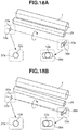
- Figs. 18A and 18B are schematic diagrams illustrating the shift in alignment described above.
- Fig. 18A illustrates the state where the axis of the developing roller 25 is substantially parallel to the axis of the photosensitive drum 1.
- FIG. 18B illustrates the state where the axis of the developing roller 25 is not parallel to the axis of the photosensitive drum 1, i.e., the state where a shift in alignment occurs.
- the boss 13a is allowed to move in a direction away from the photosensitive drum 1 by the first hole 38a, which is a long hole.
- the boss 12a is restrained by the second hole 37a, which is a circular hole, from moving in a direction intersecting the axis of the developing roller 25.
- the developing cartridge 4 may be in the state where the axis of the developing roller 25 is not parallel to the axis of the photosensitive drum 1 (the state where a shift in alignment occurs). In this state where a shift in alignment occurs, the developing roller 25 may not be able to abut the photosensitive drum 1.
- the developing cartridge 4 includes a tension spring 40, which is an elastic member as a biasing portion or biasing member, in the end supporting member 38.
- the end supporting member 38 includes a spring fixing boss 38d, which is an elastic member supporting portion for supporting the tension spring 40.
- One end of the tension spring 40 is supported by the spring fixing boss 38d, which is an elastic member supporting portion of the end supporting member 38, and the other end is supported by the boss 13a.
- the tension spring (biasing member) 40 biases the boss 13a in a direction intersecting (desirably a direction orthogonal to) the axis of the developing roller 25.
- the boss 13a is biased in a direction opposite to the developing unit biasing direction A. That is, the boss 13a is biased in the first hole 38a in the direction in which the center of the boss 13a approaches the center of the photosensitive drum 1 (the direction in which the distance between the center of the boss 13a and the center of the photosensitive drum 1 shortens).
- this direction is the direction in which the center of the boss 13a coincides with the center of the second hole 37a.
- the center of the boss 13a approaches the center of the photosensitive drum 1 so that the distance from the center of the boss 13a to the center of the photosensitive drum 1 is the same as the distance from the center of the boss 12a to the center of the photosensitive drum 1. That is, the difference between the distance from the center of the boss 13a to the center of the photosensitive drum 1 and the distance from the center of the boss 12a to the center of the photosensitive drum 1 is smaller than the case where the tension spring 40, which is a biasing portion, is not used.
- the axis of the developing roller 25 comes close to being parallel to the axis of the photosensitive drum 1.
- the angle between the axis of the developing roller 25 and the axis of the photosensitive drum 1 is smaller than the case where the tension spring 40, which is a biasing portion, is not used. Thus, it is possible to stably cause the developing roller 25 to abut the photosensitive drum 1.
- the distance from the center of the boss 13a to the center of the photosensitive drum 1 be the same as the distance from the center of the boss 12a to the center of the photosensitive drum 1, these distances do not need to be exactly the same. Further, although it is desirable that the axis of the developing roller 25 be parallel to the axis of the photosensitive drum 1, these axes do not need to be exactly parallel.
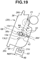
- Fig. 19 is a diagram illustrating the placement of the tension spring 40 as a biasing member. Similarly to Fig. 17 , Fig. 19 is a diagram illustrating the developing cartridge 4 as viewed from the axis direction of the developing roller 25. On the far side of the plane of the paper, the developing unit 39 is located. On the near side of the plane of the paper, the end supporting member 38 is located. For example, as illustrated in Fig. 19 , a protruding portion 13c1 or 13c2 may be provided as a part of the developing unit 39. Then, the tension spring 40 may be placed between the spring fixing boss 38d and the protruding portion 13c1. Further, the tension spring 40 may be placed between the spring fixing boss 38d and the protruding portion 13c2.
- the boss 13a can be biased in a direction intersecting (desirably a direction orthogonal to) the axis of the developing roller 25. Then, the boss 13a can approach the center of the photosensitive drum 1 in the direction intersecting (desirably a direction orthogonal to) the axis of the developing roller 25. Thus, it is possible to stably cause the developing roller 25 to abut the photosensitive drum 1.
- the tension spring 40 directly biases the boss 13a
- the tension spring 40 hardly generates a force (a moment) for rotating the developing unit 39.
- the developing roller 25 is caused to abut the photosensitive drum 1
- it is less likely that a large load is applied to the unit biasing member 80.
- the tension spring 40 is hooked to the protruding portion 13c2
- a force is applied in a direction opposite to the motion of the developing roller 25 abutting the photosensitive drum 1.
- a force is applied in a direction opposite to the motion of the developing roller 25 separating from the photosensitive drum 1.
- the boss 13a is directly biased, so that it is less likely that a large load is applied to the unit biasing member 80.
- the tension spring 40 is hooked to the protruding portion 13c1, and the developing unit 39 pivots in a direction R1 in Fig. 19 so that the developing roller 25 abuts the photosensitive drum 1.
- the protruding portion 13c1 also pivots in the direction R1 in Fig. 19 .
- the spring fixing boss 38d is provided in the end supporting member 38.
- the end supporting member 38 is fixed to the image forming apparatus.
- tension spring 40 may bias the developing unit 39, it is desirable that the tension spring 40 bias the boss 13a.
- the tension spring 40 is provided in the end supporting member 38.
- the tension spring 40 is a biasing member for, among the developing unit 39 and the end supporting member 38, biasing the developing unit 39 in a direction intersecting the axis direction of the developing roller 25.
- the end supporting member 38 and the other-end supporting member 37 are provided at the ends of the developing unit 39.
- the present invention is not limited to this configuration.
- the other-end supporting member 37 may be omitted. That is, for an end portion of the developing unit 39 on the other end side in the axis direction of the developing roller 25 (an end portion on the opposite side of the end portion for which the end supporting member 38 is provided), an apparatus-side supporting portion 137 is provided, which pivotably supports the developing unit 39.
- the apparatus-side supporting portion 137 is fixedly provided on the far side of the apparatus main body 100.
- a hole 137a (a positioning hole), which is equivalent to the second hole 37a according to the present exemplary embodiment, may be provided in the apparatus-side supporting portion 137 such that the boss 12a is a supported portion (a positioning shaft).
- the boss 12a is a positioning portion pivotably supported by the hole 137a and also restrained by the hole 137a from moving in a direction intersecting the axis of the developing roller 25.
- the boss 12a is attachable to and detachable from the hole 137a, and the developing cartridge 4 is pivotably supported by the hole 137a through the boss 12a.
- the end supporting member 38 is independent of the apparatus-side supporting portion 137 and therefore is pivotable independently of the apparatus-side supporting portion 137 and relative to the developing cartridge 4.
- the function of the apparatus-side supporting portion 137 is similar to that of the other-end supporting member 37 in the state where the developing cartridge 4 is attached to the apparatus main body 100, and therefore is not described here.
- the apparatus-side supporting portion 137 may be configured to be fixedly provided in a part of a portion obtained by extending a wall surface of the drum cartridge 9 on the far side.
- the second hole 37a is provided in the other-end supporting member 37, and the boss 12a is provided in the developing unit 39.
- the present invention is not limited to this configuration. That is, a hole equivalent to the second hole 37a (a positioning hole) according to the present exemplary embodiment may be provided in either one of the developing unit 39 and the other-end supporting member 37. In this case, a positioning shaft equivalent to the boss 12a according to the present exemplary embodiment may be placed in the other of the developing unit 39 and the other-end supporting member 37.
- a positioning shaft equivalent to the boss 12a may be provided in either one of the developing unit 39 and the apparatus-side supporting portion 137, and a hole equivalent to the second hole 37a may be provided in the other of the developing unit 39 and the apparatus-side supporting portion 137.
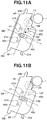
- FIG. 11A, 11B , 12 , and 13 the configuration of a developing cartridge 4 according to a second exemplary embodiment of the present invention is described.
- components different from those of the first exemplary embodiment are particularly described, and basically, components similar to those of the first exemplary embodiment are not described here.
- an end supporting member 48 (which corresponds to the end supporting member 38 in the first exemplary embodiment) is provided on one end side of a developing unit 39 in the axis direction of a developing roller 25, an end supporting member 48 (which corresponds to the end supporting member 38 in the first exemplary embodiment) is provided.
- a first hole 48a is provided, which is engaged with a boss 13a, which is provided in the developing unit 39.
- the first hole 48a is similar to the first hole 38a in the first exemplary embodiment and pivotably supports the boss 13a.
- a first engaged portion 48b and a second engaged portion 48c are provided in the end supporting member 48.
- the first engaged portion 48b and the second engaged portion 48c are engaged with a first main body engagement portion 99a and a second main body engagement portion 104e, respectively, which are provided in the apparatus main body 100 (see Fig. 13 ).
- a press lever 41 is used as a press member, and a tension spring 140 is used as a lever biasing member for biasing the press lever 41 toward the boss 13a.
- the end supporting member 48 includes the press lever 41.
- a lever supported portion 41b is formed as a press supported portion, and a spring fixing portion 41a is formed as a biasing member locking portion at a position opposed to the lever supported portion 41b.
- the end supporting member 48 includes a lever supporting boss 48e as a press supporting portion, and a spring fixing boss 48d as a biasing member locked portion.
- the lever supporting boss 48e is provided to be located in a direction opposite, with respect to the center of the first hole 48a, to the direction in which the press lever 41 moves the boss 13a.
- the lever supported portion 41b is pivotably supported by the lever supporting boss 48e.
- the press lever 41 is configured to bias the boss 13a between the lever supported portion 41b, which is a position supported by the end supporting member 48, and the spring fixing portion 41a, which is a position biased by the tension spring 140.
- the press lever 41 biases the boss 13a in a direction intersecting (desirably a direction orthogonal to) the axis of the developing roller 25.
- the distance from the lever supported portion 41b of the press lever 41 to the spring fixing portion 41a is longer than the distance from the lever supported portion 41b to the position where the press lever 41 biases the boss 13a.
- the boss 13a is biased in a direction opposite to the developing unit biasing direction A. That is, in a direction intersecting the axis direction of the developing roller 25, the boss 13a is biased in the first hole 48a in the direction in which the center of the boss 13a approaches the center of the photosensitive drum 1 (the direction in which the distance between the center of the boss 13a and the center of the photosensitive drum 1 shortens). In the present exemplary embodiment, this direction is the direction in which the center of the boss 13a coincides with the center of the second hole 37a.
- the center of the boss 13a approaches the center of the photosensitive drum 1 so that the distance from the center of the boss 13a to the center of the photosensitive drum 1 is the same as the distance from the center of the boss 12a to the center of the photosensitive drum 1. That is, the difference between the distance from the center of the boss 13a to the center of the photosensitive drum 1 and the distance from the center of the boss 12a to the center of the photosensitive drum 1 is smaller than the case where the press lever 41, which is a biasing portion, is not used.
- the axis of the developing roller 25 comes close to being parallel to the axis of the photosensitive drum 1.
- the angle between the axis of the developing roller 25 and the axis of the photosensitive drum 1 is smaller than the case where the press lever 41, which is a biasing portion, is not used. Thus, it is possible to stably cause the developing roller 25 to abut the photosensitive drum 1.
- the distance from the center of the boss 13a to the center of the photosensitive drum 1 be the same as the distance from the center of the boss 12a to the center of the photosensitive drum 1, these distances do not need to be exactly the same. Further, although it is desirable that the axis of the developing roller 25 be parallel to the axis of the photosensitive drum 1, these axes do not need to be exactly parallel.
- press lever 41 may bias the developing unit 39, it is desirable that the press lever 41 bias the boss 13a.
- the press lever 41 and the tension spring 140 are provided in the end supporting member 48. Then, the press lever 41 and the tension spring 140 are biasing members for, among the developing unit 39 and the end supporting member 48, biasing the developing unit 39 in a direction intersecting the axis direction of the developing roller 25.
- the developing frame member 31 is filled with toner, and the toner supply roller 34 and the developing roller 25 are assembled.
- the developing unit 39 is thus assembled (a first step).
- the end supporting member 48 is attached to the developing unit 39 subjected to the first step (a second step).
- the developing cartridge 4 is assembled.
- the other-end supporting member 37 may be attached to the developing unit 39 in another step.
- a developing cartridge 4 according to a third exemplary embodiment of the present invention is described.
- components different from those of the first and second exemplary embodiments are particularly described, and basically, components similar to those of the first and second exemplary embodiments are not described here.
- the developing unit 39 includes the boss 13a.
- the first holes 38a and 48a are included in the end supporting members 38 and 48, respectively.
- a first shaft (which is equivalent to the boss 13a) as a supporting shaft may be provided in either one of the developing unit and the end supporting member.
- a first hole to be engaged with the first shaft as a supporting shaft may be provided in the other of the developing unit and the end supporting member.
- the boss 12a may be provided in either one of the developing unit 39 and the other-end supporting member 37.
- the second hole 37a to be engaged with the boss 12a may be provided in the other of the developing unit 39 and the other-end supporting member 37.
- FIG. 20 is a schematic cross-sectional view illustrating the configuration of the developing cartridge 4 according to the present exemplary embodiment.
- Fig. 20 is a cross-sectional view of the developing cartridge 4 as viewed from a direction orthogonal to the axis of a developing roller 25.
- a boss 138a (which is equivalent to the boss 13a in the first and second exemplary embodiments) is provided as a supporting shaft (a first shaft).
- a first hole 139a (which is equivalent to the first hole 38a in the first and second exemplary embodiments) is provided as a supporting hole.
- the boss 12a is provided in either one of the developing unit 139 and the other-end supporting member 37.
- the second hole 37a to be engaged with the boss 12a is provided in the other of the developing unit 139 and the other-end supporting member 37.
- the first hole 139a and the boss 138a are engaged with each other, and the second hole 37a and the boss 12a are engaged with each other.
- the first hole 139a is allowed to move relative to the boss 138a in a direction intersecting the axis direction of the developing roller 25. Consequently, the developing unit 139 is pivotably supported by the end supporting member 138 and allowed to move in the direction intersecting the axis direction of the developing roller 25.
- the second hole 37a restrains the boss 12a from moving in the direction intersecting the axis direction of the developing roller 25.
- the developing unit 139 is pivotably supported by the other-end supporting member 37 and restrained from moving in the direction intersecting the axis direction of the developing roller 25.
- the developing unit 139 pivots about the bosses 12a and 138a such that a line connecting the bosses 12a and 138a is the pivotal center. Therefore, the developing roller 25 can abut the photosensitive drum 1 and separate from the photosensitive drum 1.
- Figs. 21A and 21B are diagrams illustrating the developing cartridge 4 according to the present exemplary embodiment as viewed from the axis direction of the developing roller 25.
- the end supporting member 138 and the other-end supporting member 37 are each pivotable independently of the developing unit 139. Further, in the state where the developing cartridge 4 is attached to the image forming apparatus, the end supporting member 138 and the other-end supporting member 37 are positioned relative to the image forming apparatus. Further, the photosensitive drum 1 is also positioned relative to the image forming apparatus through the drum cartridge 9.
- the biased portion 31e of the developing frame member 31 is biased in a developing unit biasing direction A1 by the unit biasing member 80 of the apparatus main body 100. Then, the developing unit 139 pivots in the direction of an arrow R1, and the developing roller 25 abuts the photosensitive drum 1. Similarly to the other exemplary embodiments, if the biased portion 31e is biased in a developing unit biasing direction A2, the developing roller 25 separates from the photosensitive drum 1.
- the developing unit 139 pivots, and the developing roller 25 is going to abut the photosensitive drum 1.
- the first hole 139a which is a long hole, moves in a direction away from the photosensitive drum 1.
- the boss 138a is provided in the end supporting member 138, the position of the boss 138a relative to the photosensitive drum 1 does not change.
- the boss 12a and the second hole 37a which is a circular hole, on the opposite side are restrained from moving in the direction intersecting the axis of the developing roller 25.
- the developing cartridge 4 is in the state where the axis of the developing roller 25 is oblique relative to the axis of the photosensitive drum 1, i.e., the state where a shift in alignment occurs in the developing unit 139.
- Figs. 22A and 22B are, similarly to Figs. 18A and 18B in the first exemplary embodiment, schematic diagrams illustrating the shift in alignment described above.
- Fig. 22A illustrates the state where the axis of the developing roller 25 is substantially parallel to the axis of the photosensitive drum 1.
- Fig. 22B illustrates the state where the axis of the developing roller 25 is not parallel to the axis of the photosensitive drum 1, i.e., the state where a shift in alignment occurs.
- the first hole 139a which is a long hole, moves in a direction away from the photosensitive drum 1 while being engaged with the boss 138a.
- the boss 12a and the second hole 37a which is a circular hole, are restrained from moving in a direction intersecting the axis of the developing roller 25.
- the developing cartridge 4 is in the state where the axis of the developing roller 25 is not parallel to the axis of the photosensitive drum 1. In this state where a shift in alignment occurs, the developing roller 25 may not be able to abut the photosensitive drum 1.
- the developing cartridge 4 includes a tension spring 240, which is an elastic member as a biasing portion, in the developing unit 139.
- the developing unit 139 includes a spring fixing boss 239d, which is an elastic member supporting portion for supporting the tension spring 240.
- One end of the tension spring 240 is supported by the spring fixing boss 239d, which is an elastic member supporting portion of the developing unit 139, and the other end is supported by the boss 138a of the end supporting member 138.
- the tension spring 240 biases the boss 138a in a direction intersecting (desirably a direction orthogonal to) the axis of the developing roller 25. That is, as illustrated in Fig. 23A , the boss 138a is biased by the tension spring 240 so that the first hole 139a moves in a direction opposite to the developing unit biasing direction A1.
- the tension spring 240 biases the boss 138a so that the center of the first hole 139a moves in a direction opposite to the developing unit biasing direction A1. Then, the center of the first hole 139a moves in the direction in which the center of the first hole 139a approaches the center of the photosensitive drum 1 (the direction in which the distance between the center of the first hole 139a and the center of the photosensitive drum 1 shortens). In the present exemplary embodiment, this direction is the direction in which the center of the first hole 139a coincides with the center of the second hole 37a or the boss 12a.
- the center of the first hole 139a approaches the center of the photosensitive drum 1 so that the distance from the center of the first hole 139a to the center of the photosensitive drum 1 is the same as the distance from the center of the second hole 37a or the boss 12a to the center of the photosensitive drum 1. That is, the difference between the distance from the center of the first hole 139a to the center of the photosensitive drum 1 and the distance from the center of the second hole 37a or the boss 12a to the center of the photosensitive drum 1 is smaller than the case where the tension spring 240, which is a biasing portion, is not used. Then, the axis of the developing roller 25 comes close to being parallel to the axis of the photosensitive drum 1.
- the angle between the axis of the developing roller 25 and the axis of the photosensitive drum 1 is smaller than the case where the tension spring 240, which is a biasing portion, is not used. Thus, it is possible to stably cause the developing roller 25 to abut the photosensitive drum 1.
- the distance from the center of the first hole 139a to the center of the photosensitive drum 1 be the same as the distance from the center of the second hole 37a or the boss 12a to the center of the photosensitive drum 1, these distances do not need to be exactly the same. Further, although it is desirable that the axis of the developing roller 25 be parallel to the axis of the photosensitive drum 1, these axes do not need to be exactly parallel.
- the tension spring 240 may bias the end supporting member 138, it is desirable that the tension spring 240 bias the boss 138a.
- the tension spring 240 is provided in the developing unit 139.
- the tension spring 240 is a biasing member for, among the developing unit 139 and the end supporting member 138, biasing the end supporting member 138 in a direction intersecting the axis direction of the developing roller 25.
- a press lever and a lever biasing member can also be used as biasing members as described in the second exemplary embodiment.
- a press lever 241 and a tension spring 340 which biases the press lever 241 toward the boss 138a, are used.
- the developing unit 139 includes the press lever 241.
- the press lever 241 includes a lever supported portion 241b as a press supported portion, and a spring fixing portion 241a as a biasing member locking portion at a position opposed to the lever supported portion 241b.
- the developing unit 139 includes a lever supporting boss 139e as a press supporting portion, and a spring fixing boss 139d as a biasing member locked portion.
- the lever supporting boss 139e is provided to be located in a direction opposite, with respect to the center of the boss 138a, to the direction in which the press lever 241 presses the boss 138a, and the developing unit 139 moves.
- the lever supported portion 241b is pivotably supported by the lever supporting boss 139e.
- the tension spring 340 is supported by the spring fixing portion 241a, and the other end is supported by the spring fixing boss 139d. Further, the press lever 241 is configured to bias the boss 138a between the lever supported portion 241b, which is in a position supported by the developing unit 139, and the spring fixing portion 241a, which is in a position biased by the tension spring 340.
- the press lever 241 biases the boss 138a in a direction intersecting (desirably a direction orthogonal to) the axis of the developing roller 25.
- the press lever 241 and the tension spring 340 bias the boss 138a so that the center of the first hole 139a moves in a direction opposite to the developing unit biasing direction A1.
- the center of the first hole 139a moves by the press lever 241 and the tension spring 340 in the direction in which the center of the first hole 139a approaches the center of the photosensitive drum 1 (the direction in which the distance between the center of the first hole 139a and the center of the photosensitive drum 1 shortens).
- this direction is the direction in which the center of the first hole 139a coincides with the center of the second hole 37a or the boss 12a.
- the center of the first hole 139a approaches the center of the photosensitive drum 1 so that the distance from the center of the first hole 139a to the center of the photosensitive drum 1 is the same as the distance from the center of the second hole 37a or the boss 12a to the center of the photosensitive drum 1. That is, the difference between the distance from the center of the first hole 139a to the center of the photosensitive drum 1 and the distance from the center of the second hole 37a or the boss 12a to the center of the photosensitive drum 1 is smaller than the case where the press lever 241, which is a biasing portion, is not used. Then, the axis of the developing roller 25 comes close to being parallel to the axis of the photosensitive drum 1.
- the angle between the axis of the developing roller 25 and the axis of the photosensitive drum 1 is smaller than the case where the press lever 241 is not used. Thus, it is possible to stably cause the developing roller 25 to abut the photosensitive drum 1.
- the distance from the center of the first hole 139a to the center of the photosensitive drum 1 be the same as the distance from the center of the second hole 37a or the boss 12a to the center of the photosensitive drum 1, these distances do not need to be exactly the same. Further, although it is desirable that the axis of the developing roller 25 be parallel to the axis of the photosensitive drum 1, these axes do not need to be exactly parallel.
- the press lever 241 may bias the end supporting member 138, it is desirable that the press lever 241 bias the boss 138a.
- the press lever 241 and the tension spring 340 are provided in the developing unit 139.
- the press lever 241 and the tension spring 340 are biasing members for, among the developing unit 139 and the end supporting member 138, biasing the end supporting member 138 in a direction intersecting the axis direction of the developing roller 25.
Landscapes
- Physics & Mathematics (AREA)
- General Physics & Mathematics (AREA)
- Engineering & Computer Science (AREA)
- Computer Vision & Pattern Recognition (AREA)
- Electrophotography Configuration And Component (AREA)
- Dry Development In Electrophotography (AREA)
Applications Claiming Priority (2)
| Application Number | Priority Date | Filing Date | Title |
|---|---|---|---|
| JP2016056987 | 2016-03-22 | ||
| JP2017031355A JP7076945B2 (ja) | 2016-03-22 | 2017-02-22 | 現像装置及び画像形成装置 |
Publications (3)
| Publication Number | Publication Date |
|---|---|
| EP3223082A2 true EP3223082A2 (de) | 2017-09-27 |
| EP3223082A3 EP3223082A3 (de) | 2017-12-27 |
| EP3223082B1 EP3223082B1 (de) | 2021-06-23 |
Family
ID=58401473
Family Applications (1)
| Application Number | Title | Priority Date | Filing Date |
|---|---|---|---|
| EP17162296.2A Active EP3223082B1 (de) | 2016-03-22 | 2017-03-22 | Entwicklungsvorrichtung und bilderzeugungseinrichtung |
Country Status (3)
| Country | Link |
|---|---|
| US (1) | US10241438B2 (de) |
| EP (1) | EP3223082B1 (de) |
| CN (1) | CN107219742B (de) |
Cited By (1)
| Publication number | Priority date | Publication date | Assignee | Title |
|---|---|---|---|---|
| EP3462243A1 (de) * | 2017-09-29 | 2019-04-03 | Canon Kabushiki Kaisha | Entwicklungsvorrichtung und bilderzeugungsvorrichtung |
Families Citing this family (3)
| Publication number | Priority date | Publication date | Assignee | Title |
|---|---|---|---|---|
| US10156825B2 (en) * | 2016-02-29 | 2018-12-18 | Canon Kabushiki Kaisha | Developing apparatus with independently rotatable members supporting a developing frame body, process cartridge, and image forming apparatus |
| JP2020101687A (ja) * | 2018-12-21 | 2020-07-02 | キヤノン株式会社 | 現像装置、プロセスカートリッジ及び画像形成装置 |
| JP7484219B2 (ja) * | 2020-02-28 | 2024-05-16 | 富士フイルムビジネスイノベーション株式会社 | 画像形成装置 |
Citations (1)
| Publication number | Priority date | Publication date | Assignee | Title |
|---|---|---|---|---|
| JP2013182036A (ja) | 2012-02-29 | 2013-09-12 | Brother Ind Ltd | 画像形成装置 |
Family Cites Families (17)
| Publication number | Priority date | Publication date | Assignee | Title |
|---|---|---|---|---|
| DE69207229T2 (de) * | 1991-03-01 | 1996-06-20 | Canon Kk | Bilderzeugungssystem und eine in diesem eingesetzte entfernbare Arbeitseinheit |
| JPH0772675A (ja) | 1993-06-28 | 1995-03-17 | Matsushita Graphic Commun Syst Inc | プロセスカートリッジ |
| JPH09230694A (ja) * | 1996-02-27 | 1997-09-05 | Canon Inc | 電子写真画像形成装置 |
| JP2001005285A (ja) | 1999-06-24 | 2001-01-12 | Canon Inc | 現像装置及びクリーニング装置及びプロセスカートリッジ及び画像形成装置 |
| JP4296497B2 (ja) | 2004-02-27 | 2009-07-15 | ブラザー工業株式会社 | 画像形成装置 |
| KR100605165B1 (ko) * | 2004-08-13 | 2006-07-28 | 삼성전자주식회사 | 화상형성장치 |
| JP2006058705A (ja) | 2004-08-20 | 2006-03-02 | Ricoh Co Ltd | プロセスカートリッジ及びそのプロセスカートリッジを有する画像形成装置 |
| JP4684732B2 (ja) * | 2005-04-27 | 2011-05-18 | キヤノン株式会社 | 電子写真画像形成装置およびプロセスカートリッジ |
| CN101371202B (zh) * | 2006-01-11 | 2011-07-20 | 佳能株式会社 | 处理盒和成像设备 |
| JP4458377B2 (ja) * | 2007-06-29 | 2010-04-28 | キヤノン株式会社 | プロセスカートリッジ及び電子写真画像形成装置 |
| JP4683670B2 (ja) * | 2009-04-17 | 2011-05-18 | キヤノン株式会社 | 電子写真画像形成装置、プロセスカートリッジ、及び、現像カートリッジ |
| US8995875B2 (en) * | 2012-03-16 | 2015-03-31 | Brother Kogyo Kabushiki Kaisha | Image forming apparatus provided with contacting-separating member capable of moving developing roller relative to photosensitive drum |
| JP5523503B2 (ja) * | 2012-05-24 | 2014-06-18 | キヤノン株式会社 | プロセスカートリッジ及び画像形成装置 |
| JP5362086B1 (ja) | 2012-09-11 | 2013-12-11 | キヤノン株式会社 | プロセスカートリッジおよび画像形成装置 |
| JP6091180B2 (ja) * | 2012-11-21 | 2017-03-08 | キヤノン株式会社 | 画像形成装置 |
| JP6184311B2 (ja) * | 2012-12-14 | 2017-08-23 | キヤノン株式会社 | プロセスカートリッジ及び画像形成装置 |
| JP6376782B2 (ja) * | 2014-03-10 | 2018-08-22 | キヤノン株式会社 | カートリッジ及び画像形成装置 |
-
2017
- 2017-03-20 US US15/463,357 patent/US10241438B2/en active Active
- 2017-03-21 CN CN201710167443.3A patent/CN107219742B/zh active Active
- 2017-03-22 EP EP17162296.2A patent/EP3223082B1/de active Active
Patent Citations (1)
| Publication number | Priority date | Publication date | Assignee | Title |
|---|---|---|---|---|
| JP2013182036A (ja) | 2012-02-29 | 2013-09-12 | Brother Ind Ltd | 画像形成装置 |
Cited By (3)
| Publication number | Priority date | Publication date | Assignee | Title |
|---|---|---|---|---|
| EP3462243A1 (de) * | 2017-09-29 | 2019-04-03 | Canon Kabushiki Kaisha | Entwicklungsvorrichtung und bilderzeugungsvorrichtung |
| CN109581838A (zh) * | 2017-09-29 | 2019-04-05 | 佳能株式会社 | 显影装置和成像装置 |
| US10670986B2 (en) | 2017-09-29 | 2020-06-02 | Canon Kabushiki Kaisha | Developing apparatus and image forming apparatus |
Also Published As
| Publication number | Publication date |
|---|---|
| US20170277071A1 (en) | 2017-09-28 |
| EP3223082A3 (de) | 2017-12-27 |
| US10241438B2 (en) | 2019-03-26 |
| CN107219742A (zh) | 2017-09-29 |
| CN107219742B (zh) | 2021-06-15 |
| EP3223082B1 (de) | 2021-06-23 |
Similar Documents
| Publication | Publication Date | Title |
|---|---|---|
| KR102333305B1 (ko) | 화상형성장치의 본체에 장착가능한 현상 카트리지 | |
| KR102251926B1 (ko) | 화상형성장치의 본체에 장착가능한 현상 카트리지 | |
| EP3211482A1 (de) | Entwicklungskartusche und bilderzeugungsvorrichtung | |
| CN107315334B (zh) | 显影设备和图像形成装置 | |
| EP3223082B1 (de) | Entwicklungsvorrichtung und bilderzeugungseinrichtung | |
| CN105929656B (zh) | 显影剂容器、显影装置、处理盒和成像设备 | |
| JP6137786B2 (ja) | 現像装置、プロセスカートリッジ、画像形成装置 | |
| KR102100541B1 (ko) | 현상 장치 및 화상 형성 장치 | |
| JP2016161714A (ja) | 現像装置、プロセスカートリッジ及び画像形成装置 | |
| JP6938166B2 (ja) | 画像形成装置 | |
| US9110395B2 (en) | Image forming apparatus and cartridge | |
| US10018961B2 (en) | Image forming apparatus having a rotatable development carrying member disposed in a particular relation to a developer supply roller | |
| JP7214419B2 (ja) | 画像形成装置、現像カートリッジ | |
| EP3462243B1 (de) | Entwicklungsvorrichtung und bilderzeugungsvorrichtung | |
| CN110941167B (zh) | 成像设备和显影盒 | |
| JP7297419B2 (ja) | 画像形成装置、現像カートリッジ | |
| KR102131649B1 (ko) | 현상장치 및 화상형성장치 | |
| JP2017156744A (ja) | 現像カートリッジ、画像形成装置 | |
| JP2019066615A (ja) | 現像装置及び画像形成装置 |
Legal Events
| Date | Code | Title | Description |
|---|---|---|---|
| PUAI | Public reference made under article 153(3) epc to a published international application that has entered the european phase |
Free format text: ORIGINAL CODE: 0009012 |
|
| STAA | Information on the status of an ep patent application or granted ep patent |
Free format text: STATUS: THE APPLICATION HAS BEEN PUBLISHED |
|
| AK | Designated contracting states |
Kind code of ref document: A2 Designated state(s): AL AT BE BG CH CY CZ DE DK EE ES FI FR GB GR HR HU IE IS IT LI LT LU LV MC MK MT NL NO PL PT RO RS SE SI SK SM TR |
|
| AX | Request for extension of the european patent |
Extension state: BA ME |
|
| PUAL | Search report despatched |
Free format text: ORIGINAL CODE: 0009013 |
|
| AK | Designated contracting states |
Kind code of ref document: A3 Designated state(s): AL AT BE BG CH CY CZ DE DK EE ES FI FR GB GR HR HU IE IS IT LI LT LU LV MC MK MT NL NO PL PT RO RS SE SI SK SM TR |
|
| AX | Request for extension of the european patent |
Extension state: BA ME |
|
| RIC1 | Information provided on ipc code assigned before grant |
Ipc: G03G 21/18 20060101AFI20171122BHEP Ipc: G03G 15/08 20060101ALI20171122BHEP |
|
| STAA | Information on the status of an ep patent application or granted ep patent |
Free format text: STATUS: REQUEST FOR EXAMINATION WAS MADE |
|
| 17P | Request for examination filed |
Effective date: 20180627 |
|
| RBV | Designated contracting states (corrected) |
Designated state(s): AL AT BE BG CH CY CZ DE DK EE ES FI FR GB GR HR HU IE IS IT LI LT LU LV MC MK MT NL NO PL PT RO RS SE SI SK SM TR |
|
| STAA | Information on the status of an ep patent application or granted ep patent |
Free format text: STATUS: EXAMINATION IS IN PROGRESS |
|
| 17Q | First examination report despatched |
Effective date: 20190509 |
|
| GRAP | Despatch of communication of intention to grant a patent |
Free format text: ORIGINAL CODE: EPIDOSNIGR1 |
|
| STAA | Information on the status of an ep patent application or granted ep patent |
Free format text: STATUS: GRANT OF PATENT IS INTENDED |
|
| INTG | Intention to grant announced |
Effective date: 20200805 |
|
| GRAJ | Information related to disapproval of communication of intention to grant by the applicant or resumption of examination proceedings by the epo deleted |
Free format text: ORIGINAL CODE: EPIDOSDIGR1 |
|
| STAA | Information on the status of an ep patent application or granted ep patent |
Free format text: STATUS: EXAMINATION IS IN PROGRESS |
|
| INTC | Intention to grant announced (deleted) | ||
| GRAP | Despatch of communication of intention to grant a patent |
Free format text: ORIGINAL CODE: EPIDOSNIGR1 |
|
| STAA | Information on the status of an ep patent application or granted ep patent |
Free format text: STATUS: GRANT OF PATENT IS INTENDED |
|
| INTG | Intention to grant announced |
Effective date: 20210114 |
|
| GRAS | Grant fee paid |
Free format text: ORIGINAL CODE: EPIDOSNIGR3 |
|
| GRAA | (expected) grant |
Free format text: ORIGINAL CODE: 0009210 |
|
| STAA | Information on the status of an ep patent application or granted ep patent |
Free format text: STATUS: THE PATENT HAS BEEN GRANTED |
|
| AK | Designated contracting states |
Kind code of ref document: B1 Designated state(s): AL AT BE BG CH CY CZ DE DK EE ES FI FR GB GR HR HU IE IS IT LI LT LU LV MC MK MT NL NO PL PT RO RS SE SI SK SM TR |
|
| REG | Reference to a national code |
Ref country code: GB Ref legal event code: FG4D |
|
| REG | Reference to a national code |
Ref country code: CH Ref legal event code: EP |
|
| REG | Reference to a national code |
Ref country code: DE Ref legal event code: R096 Ref document number: 602017040644 Country of ref document: DE Ref country code: AT Ref legal event code: REF Ref document number: 1404812 Country of ref document: AT Kind code of ref document: T Effective date: 20210715 |
|
| REG | Reference to a national code |
Ref country code: IE Ref legal event code: FG4D |
|
| REG | Reference to a national code |
Ref country code: LT Ref legal event code: MG9D |
|
| PG25 | Lapsed in a contracting state [announced via postgrant information from national office to epo] |
Ref country code: FI Free format text: LAPSE BECAUSE OF FAILURE TO SUBMIT A TRANSLATION OF THE DESCRIPTION OR TO PAY THE FEE WITHIN THE PRESCRIBED TIME-LIMIT Effective date: 20210623 Ref country code: LT Free format text: LAPSE BECAUSE OF FAILURE TO SUBMIT A TRANSLATION OF THE DESCRIPTION OR TO PAY THE FEE WITHIN THE PRESCRIBED TIME-LIMIT Effective date: 20210623 Ref country code: HR Free format text: LAPSE BECAUSE OF FAILURE TO SUBMIT A TRANSLATION OF THE DESCRIPTION OR TO PAY THE FEE WITHIN THE PRESCRIBED TIME-LIMIT Effective date: 20210623 Ref country code: BG Free format text: LAPSE BECAUSE OF FAILURE TO SUBMIT A TRANSLATION OF THE DESCRIPTION OR TO PAY THE FEE WITHIN THE PRESCRIBED TIME-LIMIT Effective date: 20210923 |
|
| REG | Reference to a national code |
Ref country code: AT Ref legal event code: MK05 Ref document number: 1404812 Country of ref document: AT Kind code of ref document: T Effective date: 20210623 |
|
| PG25 | Lapsed in a contracting state [announced via postgrant information from national office to epo] |
Ref country code: LV Free format text: LAPSE BECAUSE OF FAILURE TO SUBMIT A TRANSLATION OF THE DESCRIPTION OR TO PAY THE FEE WITHIN THE PRESCRIBED TIME-LIMIT Effective date: 20210623 Ref country code: GR Free format text: LAPSE BECAUSE OF FAILURE TO SUBMIT A TRANSLATION OF THE DESCRIPTION OR TO PAY THE FEE WITHIN THE PRESCRIBED TIME-LIMIT Effective date: 20210924 Ref country code: NO Free format text: LAPSE BECAUSE OF FAILURE TO SUBMIT A TRANSLATION OF THE DESCRIPTION OR TO PAY THE FEE WITHIN THE PRESCRIBED TIME-LIMIT Effective date: 20210923 Ref country code: SE Free format text: LAPSE BECAUSE OF FAILURE TO SUBMIT A TRANSLATION OF THE DESCRIPTION OR TO PAY THE FEE WITHIN THE PRESCRIBED TIME-LIMIT Effective date: 20210623 Ref country code: RS Free format text: LAPSE BECAUSE OF FAILURE TO SUBMIT A TRANSLATION OF THE DESCRIPTION OR TO PAY THE FEE WITHIN THE PRESCRIBED TIME-LIMIT Effective date: 20210623 |
|
| REG | Reference to a national code |
Ref country code: NL Ref legal event code: MP Effective date: 20210623 |
|
| PG25 | Lapsed in a contracting state [announced via postgrant information from national office to epo] |
Ref country code: SK Free format text: LAPSE BECAUSE OF FAILURE TO SUBMIT A TRANSLATION OF THE DESCRIPTION OR TO PAY THE FEE WITHIN THE PRESCRIBED TIME-LIMIT Effective date: 20210623 Ref country code: SM Free format text: LAPSE BECAUSE OF FAILURE TO SUBMIT A TRANSLATION OF THE DESCRIPTION OR TO PAY THE FEE WITHIN THE PRESCRIBED TIME-LIMIT Effective date: 20210623 Ref country code: CZ Free format text: LAPSE BECAUSE OF FAILURE TO SUBMIT A TRANSLATION OF THE DESCRIPTION OR TO PAY THE FEE WITHIN THE PRESCRIBED TIME-LIMIT Effective date: 20210623 Ref country code: EE Free format text: LAPSE BECAUSE OF FAILURE TO SUBMIT A TRANSLATION OF THE DESCRIPTION OR TO PAY THE FEE WITHIN THE PRESCRIBED TIME-LIMIT Effective date: 20210623 Ref country code: AT Free format text: LAPSE BECAUSE OF FAILURE TO SUBMIT A TRANSLATION OF THE DESCRIPTION OR TO PAY THE FEE WITHIN THE PRESCRIBED TIME-LIMIT Effective date: 20210623 Ref country code: NL Free format text: LAPSE BECAUSE OF FAILURE TO SUBMIT A TRANSLATION OF THE DESCRIPTION OR TO PAY THE FEE WITHIN THE PRESCRIBED TIME-LIMIT Effective date: 20210623 Ref country code: PT Free format text: LAPSE BECAUSE OF FAILURE TO SUBMIT A TRANSLATION OF THE DESCRIPTION OR TO PAY THE FEE WITHIN THE PRESCRIBED TIME-LIMIT Effective date: 20211025 Ref country code: RO Free format text: LAPSE BECAUSE OF FAILURE TO SUBMIT A TRANSLATION OF THE DESCRIPTION OR TO PAY THE FEE WITHIN THE PRESCRIBED TIME-LIMIT Effective date: 20210623 Ref country code: ES Free format text: LAPSE BECAUSE OF FAILURE TO SUBMIT A TRANSLATION OF THE DESCRIPTION OR TO PAY THE FEE WITHIN THE PRESCRIBED TIME-LIMIT Effective date: 20210623 |
|
| PG25 | Lapsed in a contracting state [announced via postgrant information from national office to epo] |
Ref country code: PL Free format text: LAPSE BECAUSE OF FAILURE TO SUBMIT A TRANSLATION OF THE DESCRIPTION OR TO PAY THE FEE WITHIN THE PRESCRIBED TIME-LIMIT Effective date: 20210623 |
|
| REG | Reference to a national code |
Ref country code: DE Ref legal event code: R097 Ref document number: 602017040644 Country of ref document: DE |
|
| PG25 | Lapsed in a contracting state [announced via postgrant information from national office to epo] |
Ref country code: DK Free format text: LAPSE BECAUSE OF FAILURE TO SUBMIT A TRANSLATION OF THE DESCRIPTION OR TO PAY THE FEE WITHIN THE PRESCRIBED TIME-LIMIT Effective date: 20210623 |
|
| PLBE | No opposition filed within time limit |
Free format text: ORIGINAL CODE: 0009261 |
|
| STAA | Information on the status of an ep patent application or granted ep patent |
Free format text: STATUS: NO OPPOSITION FILED WITHIN TIME LIMIT |
|
| 26N | No opposition filed |
Effective date: 20220324 |
|
| PG25 | Lapsed in a contracting state [announced via postgrant information from national office to epo] |
Ref country code: AL Free format text: LAPSE BECAUSE OF FAILURE TO SUBMIT A TRANSLATION OF THE DESCRIPTION OR TO PAY THE FEE WITHIN THE PRESCRIBED TIME-LIMIT Effective date: 20210623 |
|
| PG25 | Lapsed in a contracting state [announced via postgrant information from national office to epo] |
Ref country code: IT Free format text: LAPSE BECAUSE OF FAILURE TO SUBMIT A TRANSLATION OF THE DESCRIPTION OR TO PAY THE FEE WITHIN THE PRESCRIBED TIME-LIMIT Effective date: 20210623 |
|
| PG25 | Lapsed in a contracting state [announced via postgrant information from national office to epo] |
Ref country code: MC Free format text: LAPSE BECAUSE OF FAILURE TO SUBMIT A TRANSLATION OF THE DESCRIPTION OR TO PAY THE FEE WITHIN THE PRESCRIBED TIME-LIMIT Effective date: 20210623 |
|
| REG | Reference to a national code |
Ref country code: CH Ref legal event code: PL |
|
| REG | Reference to a national code |
Ref country code: BE Ref legal event code: MM Effective date: 20220331 |
|
| PG25 | Lapsed in a contracting state [announced via postgrant information from national office to epo] |
Ref country code: LU Free format text: LAPSE BECAUSE OF NON-PAYMENT OF DUE FEES Effective date: 20220322 Ref country code: LI Free format text: LAPSE BECAUSE OF NON-PAYMENT OF DUE FEES Effective date: 20220331 Ref country code: IE Free format text: LAPSE BECAUSE OF NON-PAYMENT OF DUE FEES Effective date: 20220322 Ref country code: CH Free format text: LAPSE BECAUSE OF NON-PAYMENT OF DUE FEES Effective date: 20220331 |
|
| PG25 | Lapsed in a contracting state [announced via postgrant information from national office to epo] |
Ref country code: BE Free format text: LAPSE BECAUSE OF NON-PAYMENT OF DUE FEES Effective date: 20220331 |
|
| PG25 | Lapsed in a contracting state [announced via postgrant information from national office to epo] |
Ref country code: HU Free format text: LAPSE BECAUSE OF FAILURE TO SUBMIT A TRANSLATION OF THE DESCRIPTION OR TO PAY THE FEE WITHIN THE PRESCRIBED TIME-LIMIT; INVALID AB INITIO Effective date: 20170322 |
|
| PG25 | Lapsed in a contracting state [announced via postgrant information from national office to epo] |
Ref country code: MK Free format text: LAPSE BECAUSE OF FAILURE TO SUBMIT A TRANSLATION OF THE DESCRIPTION OR TO PAY THE FEE WITHIN THE PRESCRIBED TIME-LIMIT Effective date: 20210623 Ref country code: CY Free format text: LAPSE BECAUSE OF FAILURE TO SUBMIT A TRANSLATION OF THE DESCRIPTION OR TO PAY THE FEE WITHIN THE PRESCRIBED TIME-LIMIT Effective date: 20210623 |
|
| PG25 | Lapsed in a contracting state [announced via postgrant information from national office to epo] |
Ref country code: MT Free format text: LAPSE BECAUSE OF FAILURE TO SUBMIT A TRANSLATION OF THE DESCRIPTION OR TO PAY THE FEE WITHIN THE PRESCRIBED TIME-LIMIT Effective date: 20210623 |
|
| PG25 | Lapsed in a contracting state [announced via postgrant information from national office to epo] |
Ref country code: TR Free format text: LAPSE BECAUSE OF FAILURE TO SUBMIT A TRANSLATION OF THE DESCRIPTION OR TO PAY THE FEE WITHIN THE PRESCRIBED TIME-LIMIT Effective date: 20210623 |
|
| PGFP | Annual fee paid to national office [announced via postgrant information from national office to epo] |
Ref country code: GB Payment date: 20260220 Year of fee payment: 10 |
|
| PGFP | Annual fee paid to national office [announced via postgrant information from national office to epo] |
Ref country code: DE Payment date: 20260219 Year of fee payment: 10 |
|
| PGFP | Annual fee paid to national office [announced via postgrant information from national office to epo] |
Ref country code: FR Payment date: 20260220 Year of fee payment: 10 |