EP3462243B1 - Entwicklungsvorrichtung und bilderzeugungsvorrichtung - Google Patents
Entwicklungsvorrichtung und bilderzeugungsvorrichtung Download PDFInfo
- Publication number
- EP3462243B1 EP3462243B1 EP18196533.6A EP18196533A EP3462243B1 EP 3462243 B1 EP3462243 B1 EP 3462243B1 EP 18196533 A EP18196533 A EP 18196533A EP 3462243 B1 EP3462243 B1 EP 3462243B1
- Authority
- EP
- European Patent Office
- Prior art keywords
- developing
- main body
- end portion
- apparatus main
- image forming
- Prior art date
- Legal status (The legal status is an assumption and is not a legal conclusion. Google has not performed a legal analysis and makes no representation as to the accuracy of the status listed.)
- Active
Links
Images






Classifications
-
- G—PHYSICS
- G03—PHOTOGRAPHY; CINEMATOGRAPHY; ANALOGOUS TECHNIQUES USING WAVES OTHER THAN OPTICAL WAVES; ELECTROGRAPHY; HOLOGRAPHY
- G03G—ELECTROGRAPHY; ELECTROPHOTOGRAPHY; MAGNETOGRAPHY
- G03G15/00—Apparatus for electrographic processes using a charge pattern
- G03G15/06—Apparatus for electrographic processes using a charge pattern for developing
- G03G15/08—Apparatus for electrographic processes using a charge pattern for developing using a solid developer, e.g. powder developer
- G03G15/0896—Arrangements or disposition of the complete developer unit or parts thereof not provided for by groups G03G15/08 - G03G15/0894
-
- G—PHYSICS
- G03—PHOTOGRAPHY; CINEMATOGRAPHY; ANALOGOUS TECHNIQUES USING WAVES OTHER THAN OPTICAL WAVES; ELECTROGRAPHY; HOLOGRAPHY
- G03G—ELECTROGRAPHY; ELECTROPHOTOGRAPHY; MAGNETOGRAPHY
- G03G15/00—Apparatus for electrographic processes using a charge pattern
- G03G15/06—Apparatus for electrographic processes using a charge pattern for developing
- G03G15/08—Apparatus for electrographic processes using a charge pattern for developing using a solid developer, e.g. powder developer
- G03G15/0806—Apparatus for electrographic processes using a charge pattern for developing using a solid developer, e.g. powder developer on a donor element, e.g. belt, roller
- G03G15/0808—Apparatus for electrographic processes using a charge pattern for developing using a solid developer, e.g. powder developer on a donor element, e.g. belt, roller characterised by the developer supplying means, e.g. structure of developer supply roller
-
- G—PHYSICS
- G03—PHOTOGRAPHY; CINEMATOGRAPHY; ANALOGOUS TECHNIQUES USING WAVES OTHER THAN OPTICAL WAVES; ELECTROGRAPHY; HOLOGRAPHY
- G03G—ELECTROGRAPHY; ELECTROPHOTOGRAPHY; MAGNETOGRAPHY
- G03G21/00—Arrangements not provided for by groups G03G13/00 - G03G19/00, e.g. cleaning, elimination of residual charge
- G03G21/16—Mechanical means for facilitating the maintenance of the apparatus, e.g. modular arrangements
- G03G21/18—Mechanical means for facilitating the maintenance of the apparatus, e.g. modular arrangements using a processing cartridge, whereby the process cartridge comprises at least two image processing means in a single unit
- G03G21/1803—Arrangements or disposition of the complete process cartridge or parts thereof
- G03G21/1817—Arrangements or disposition of the complete process cartridge or parts thereof having a submodular arrangement
- G03G21/1821—Arrangements or disposition of the complete process cartridge or parts thereof having a submodular arrangement means for connecting the different parts of the process cartridge, e.g. attachment, positioning of parts with each other, pressure/distance regulation
-
- G—PHYSICS
- G03—PHOTOGRAPHY; CINEMATOGRAPHY; ANALOGOUS TECHNIQUES USING WAVES OTHER THAN OPTICAL WAVES; ELECTROGRAPHY; HOLOGRAPHY
- G03G—ELECTROGRAPHY; ELECTROPHOTOGRAPHY; MAGNETOGRAPHY
- G03G15/00—Apparatus for electrographic processes using a charge pattern
- G03G15/06—Apparatus for electrographic processes using a charge pattern for developing
- G03G15/08—Apparatus for electrographic processes using a charge pattern for developing using a solid developer, e.g. powder developer
- G03G15/0806—Apparatus for electrographic processes using a charge pattern for developing using a solid developer, e.g. powder developer on a donor element, e.g. belt, roller
-
- G—PHYSICS
- G03—PHOTOGRAPHY; CINEMATOGRAPHY; ANALOGOUS TECHNIQUES USING WAVES OTHER THAN OPTICAL WAVES; ELECTROGRAPHY; HOLOGRAPHY
- G03G—ELECTROGRAPHY; ELECTROPHOTOGRAPHY; MAGNETOGRAPHY
- G03G15/00—Apparatus for electrographic processes using a charge pattern
- G03G15/06—Apparatus for electrographic processes using a charge pattern for developing
- G03G15/08—Apparatus for electrographic processes using a charge pattern for developing using a solid developer, e.g. powder developer
-
- G—PHYSICS
- G03—PHOTOGRAPHY; CINEMATOGRAPHY; ANALOGOUS TECHNIQUES USING WAVES OTHER THAN OPTICAL WAVES; ELECTROGRAPHY; HOLOGRAPHY
- G03G—ELECTROGRAPHY; ELECTROPHOTOGRAPHY; MAGNETOGRAPHY
- G03G15/00—Apparatus for electrographic processes using a charge pattern
- G03G15/06—Apparatus for electrographic processes using a charge pattern for developing
- G03G15/08—Apparatus for electrographic processes using a charge pattern for developing using a solid developer, e.g. powder developer
- G03G15/0822—Arrangements for preparing, mixing, supplying or dispensing developer
- G03G15/0865—Arrangements for supplying new developer
-
- G—PHYSICS
- G03—PHOTOGRAPHY; CINEMATOGRAPHY; ANALOGOUS TECHNIQUES USING WAVES OTHER THAN OPTICAL WAVES; ELECTROGRAPHY; HOLOGRAPHY
- G03G—ELECTROGRAPHY; ELECTROPHOTOGRAPHY; MAGNETOGRAPHY
- G03G21/00—Arrangements not provided for by groups G03G13/00 - G03G19/00, e.g. cleaning, elimination of residual charge
- G03G21/16—Mechanical means for facilitating the maintenance of the apparatus, e.g. modular arrangements
- G03G21/1661—Mechanical means for facilitating the maintenance of the apparatus, e.g. modular arrangements means for handling parts of the apparatus in the apparatus
- G03G21/1676—Mechanical means for facilitating the maintenance of the apparatus, e.g. modular arrangements means for handling parts of the apparatus in the apparatus for the developer unit
-
- G—PHYSICS
- G03—PHOTOGRAPHY; CINEMATOGRAPHY; ANALOGOUS TECHNIQUES USING WAVES OTHER THAN OPTICAL WAVES; ELECTROGRAPHY; HOLOGRAPHY
- G03G—ELECTROGRAPHY; ELECTROPHOTOGRAPHY; MAGNETOGRAPHY
- G03G21/00—Arrangements not provided for by groups G03G13/00 - G03G19/00, e.g. cleaning, elimination of residual charge
- G03G21/16—Mechanical means for facilitating the maintenance of the apparatus, e.g. modular arrangements
- G03G21/18—Mechanical means for facilitating the maintenance of the apparatus, e.g. modular arrangements using a processing cartridge, whereby the process cartridge comprises at least two image processing means in a single unit
-
- G—PHYSICS
- G03—PHOTOGRAPHY; CINEMATOGRAPHY; ANALOGOUS TECHNIQUES USING WAVES OTHER THAN OPTICAL WAVES; ELECTROGRAPHY; HOLOGRAPHY
- G03G—ELECTROGRAPHY; ELECTROPHOTOGRAPHY; MAGNETOGRAPHY
- G03G21/00—Arrangements not provided for by groups G03G13/00 - G03G19/00, e.g. cleaning, elimination of residual charge
- G03G21/16—Mechanical means for facilitating the maintenance of the apparatus, e.g. modular arrangements
- G03G21/18—Mechanical means for facilitating the maintenance of the apparatus, e.g. modular arrangements using a processing cartridge, whereby the process cartridge comprises at least two image processing means in a single unit
- G03G21/1839—Means for handling the process cartridge in the apparatus body
- G03G21/1842—Means for handling the process cartridge in the apparatus body for guiding and mounting the process cartridge, positioning, alignment, locks
- G03G21/185—Means for handling the process cartridge in the apparatus body for guiding and mounting the process cartridge, positioning, alignment, locks the process cartridge being mounted parallel to the axis of the photosensitive member
-
- G—PHYSICS
- G03—PHOTOGRAPHY; CINEMATOGRAPHY; ANALOGOUS TECHNIQUES USING WAVES OTHER THAN OPTICAL WAVES; ELECTROGRAPHY; HOLOGRAPHY
- G03G—ELECTROGRAPHY; ELECTROPHOTOGRAPHY; MAGNETOGRAPHY
- G03G2221/00—Processes not provided for by group G03G2215/00, e.g. cleaning or residual charge elimination
- G03G2221/16—Mechanical means for facilitating the maintenance of the apparatus, e.g. modular arrangements and complete machine concepts
- G03G2221/1651—Mechanical means for facilitating the maintenance of the apparatus, e.g. modular arrangements and complete machine concepts for connecting the different parts
- G03G2221/1654—Locks and means for positioning or alignment
Definitions
- the present invention relates to an electrophotographic image forming apparatus using a developing apparatus.
- an image forming apparatus such as printers, which use the electrophotographic image forming method (electrophotographic process), for the purpose of achieving easy maintenance of process means
- an image forming apparatus in which various kinds of process means are configured as a process cartridge that is removably mounted to the main body of the image forming apparatus has been put to practical use.
- the process cartridge may be dividable into some process cartridges such as a cleaning cartridge including a photosensitive drum (electrophotographic photosensitive member), a developing cartridge including developing means, and a toner cartridge configured to supply developer.
- Japanese Patent Application Laid-open No. 2013-182036 discloses an image forming apparatus in which the frame of a developing cartridge includes a first frame by which a developing roller is rotatably supported, and a second frame by which both the end portions of the first frame in the longitudinal direction of the developing roller are rotatably supported.
- the second frame is positioned with respect to the apparatus main body.
- the developing roller can be brought into contact with or separated from a photosensitive drum through pivotal movement of the first frame relative to the second frame.
- US 2009/290904 A1 discloses a developing apparatus having a photosensitive drum, a cleaning unit frame, and a developing unit frame.
- the cleaning unit frame has a front end wall as first end portion member and a rear end wall as second end portion member.
- EP 3 223 082 A2 discloses a developing apparatus with the features of the preamble of claim 1.
- the second frame has a portion configured to support one end portion of the first frame, a portion configured to support the other end portion thereof, and a portion configured to connect such portions to each other.
- the second frame extends from one end portion to the other end portion of the first frame and crosses the developing roller in the longitudinal direction. It is accordingly necessary to take a space for provision of the second frame into consideration in designing the dimensions of the developing cartridge, which is a developing apparatus. It is concerned that the space may become a factor that prevents a reduction in size of the apparatus.
- the developing apparatus can be reduced in size.
- an electrophotographic image forming apparatus is an apparatus configured to form an image on a recording material (recording medium) using the electrophotographic image forming process.
- the image forming apparatus include printers (laser beam printer, LED printer, and the like), a copying machine, a facsimile apparatus, a word processor, and a multifunction peripheral thereof (multifunction printer).
- the recording material include a recording sheet and a plastic sheet.
- a developing apparatus is an apparatus configured to develop, with developer, an electrostatic latent image formed on a drum-shaped electrophotographic photosensitive member (hereinafter referred to as "photosensitive drum”).
- the developing apparatus includes developing means, a developing unit configured to support the developing means, parts related to the developing means, and the like. Examples of the developing means include a developing roller, an applying roller, and a developing blade.
- the developing apparatus of the present embodiment is configured as a developing cartridge that is removably mounted to the apparatus main body of the image forming apparatus.
- a process cartridge includes the photosensitive drum and process means for acting on the photosensitive drum, which are entirely or partly integrated as a cartridge, and is removably mounted to the main body of the image forming apparatus.
- the process means include charging means for acting on the photosensitive drum, the developing means, and cleaning means.
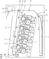
- FIG. 4 the whole configuration of an image forming apparatus 100 according to the embodiment of the present invention is described.
- four drum cartridges 9 (9Y, 9M, 9C, and 9K) and four developing apparatus (hereinafter referred to as "developing cartridges") 4 (4Y, 4M, 4C, and 4K) are removably mounted and supported inside the apparatus main body of the image forming apparatus 100 by mounting members (not shown).
- the upstream side and the downstream side in a mounting direction in which the drum cartridges 9 and the developing cartridges 4 are mounted to the image forming apparatus 100 are defined as a front-side-surface side and a back-side-surface side, respectively.
- the drum cartridge 9 and the developing cartridge 4 are provided to be adjacent to each other in a direction inclined from a horizontal surface (horizontal direction) on which the image forming apparatus 100 is installed.
- the drum cartridges 9 are obtained through integration of photosensitive drums 1 (1a, 1b, 1c, and 1d) and process means such as charging rollers 2 (2a, 2b, 2c, and 2d) and cleaning members 6 (6a, 6b, 6c, and 6d), which are arranged in the vicinity of the photosensitive drums 1. Further, the developing cartridges (4Y, 4M, 4C, and 4K) are obtained through integration of process means such as developing rollers 25 (25a, 25b, 25c, and 25d) and developing blades 35 (35a, 35b, 35c, and 35d).
- the charging roller 2 uniformly charges the surface of the photosensitive drum 1, and the developing roller 25 develops, with developer (hereinafter referred to as "toner"), a latent image formed on the photosensitive drum 1 to form a visible image.
- the cleaning member 6 removes toner remaining on the photosensitive drum 1 after the toner image formed on the photosensitive drum 1 is transferred onto a recording material S.
- a scanner unit 3 is provided below the drum cartridges 9 and the developing cartridges 4 inside the apparatus main body. The scanner unit 3 selectively exposes the photosensitive drums 1 on the basis of image information to form latent images on the photosensitive drums 1.
- a cassette 17 in which the recording materials S are stored is mounted in the lower portion of the image forming apparatus 100.
- recording medium transport means is provided so that the recording material S is conveyed to the upper part of the image forming apparatus 100 through a secondary transfer roller 69 and a fixing portion 74.
- a feed roller 54 configured to separately feed the recording materials S in the cassette 17 one by one
- a conveyance roller pair 76 configured to convey the fed recording material S
- a registration roller pair 55 configured to synchronize a latent image formed on the photosensitive drum 1 and the recording material S.
- An intermediate transfer unit 5 is provided above the drum cartridges 9 and the developing cartridges 4 inside the apparatus main body.
- the intermediate transfer unit 5 is intermediate transfer means for transferring toner images formed on the respective photosensitive drums 1 (1a, 1b, 1c, and 1d).
- the intermediate transfer unit 5 includes a driver roller 56, a driven roller 57, primary transfer rollers 58 (58a, 58b, 58c, and 58d) arranged at positions opposed to the photosensitive drums 1 of the respective colors, and a counter roller 59 arranged at a position opposed to the secondary transfer roller 69.
- a transfer belt 14 is looped around the intermediate transfer unit 5.
- the transfer belt 14 faces all the photosensitive drums 1 and circulates (rotates in the direction A) while being in contact with the photosensitive drums 1.
- a toner image is primarily transferred from the photosensitive drum 1 onto the transfer belt 14 through voltage application to the primary transfer rollers 58 (58a, 58b, 58c, and 58d). Then, the toner image on the transfer belt 14 is transferred onto the recording material S through voltage application to the counter roller 59, which is arranged on the inner side of the transfer belt 14, and the secondary transfer roller 69.
- each photosensitive drum 1 rotates, and the scanner unit 3 selectively exposes the photosensitive drums 1 uniformly charged by the charging rollers 2. With this, electrostatic latent images are formed on the photosensitive drums 1.
- the latent images are developed by the developing roller 25. In this way, toner images of the respective colors are formed on the respective photosensitive drums 1.
- the registration roller pair 55 conveys the recording material S to a secondary transfer position where the counter roller 59 and the secondary transfer roller 69 are in contact with each other through the transfer belt 14. Then, the toner images of the respective colors on the transfer belt 14 are secondarily transferred onto the recording material S through application of transfer bias voltage to the secondary transfer roller 69.
- the recording material S having the color image formed thereon are heated and pressurized by the fixing portion 74 so that the toner image is fixed. Thereafter, the recording material S is discharged to a discharging portion 75 by a discharging roller 72.
- the fixing portion 74 is arranged in the upper portion of the image forming apparatus 100.
- drum cartridges 9 in the present embodiment are described.
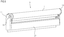
- FIG. 5 is an explanatory view of the configuration of the drum cartridges 9 (9Y, 9M, 9C, and 9K).
- the drum cartridges 9Y, 9M, 9C, and 9K have the same configuration except for toner colors (yellow (Y), magenta (M), cyan (C), and black (K)) that are used in the drum cartridges 9Y, 9M, 9C, and 9K.
- toner colors yellow (Y), magenta (M), cyan (C), and black (K)
- the upstream side and the downstream side of the insertion direction are defined as the front side and the back side, respectively.
- the photosensitive drum 1 is rotationally provided to a cleaning frame 27 of the drum cartridge 9 (9Y, 9M, 9C, or 9K) via a drum-front bearing 10 and a drum-back bearing 11.
- a drum coupling 16 and a flange are provided at one end of the photosensitive drum 1 in an axial direction thereof.
- FIG. 6 is a schematic sectional view of the drum cartridge 9.
- the charging roller 2 and the cleaning member 6 are provided in the vicinity of the photosensitive drum 1.
- the photosensitive drum 1 drives to rotate on the basis of image forming operation when the drum cartridge 9 receives driving force transmitted from an apparatus drive motor (not shown), which is a driving source.
- the charging roller 2 is rotationally attached to the drum cartridge 9 via a charging roller bearing 28.
- the charging roller 2 is pressurized toward the photosensitive drum 1 by a charging roller pressurizing member 33, which is a spring, for example, and rotates along rotation of the photosensitive drum 1.
- the cleaning member 6 includes an elastic member 7 made up of a rubber blade, and a cleaning supporting member 8.
- a leading-edge portion 7a of the elastic member 7 is arranged to be in contact with the photosensitive drum 1 while being directed to a direction opposite to the rotation direction (clockwise direction in FIG. 6 ) of the photosensitive drum 1. Residual toner removed from the surface of the photosensitive drum 1 by the cleaning member 6 is dropped off to a removed toner chamber 27a.
- a squeegee sheet 21 configured to prevent leakage of removed toner from the removed toner chamber 27a is in contact with the photosensitive drum 1.
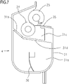
- FIG. 7 is a schematic main sectional view of the developing cartridge 4 (4Y, 4M, 4C, or 4K) in which toner is stored.
- the developing cartridges 4Y, 4M, 4C, and 4K have the same configuration except for the colors of stored toner. Specifically, the developing cartridge 4Y having yellow toner stored therein, the developing cartridge 4M having magenta toner stored therein, the developing cartridge 4C having cyan toner stored therein, and the developing cartridge 4K having black toner stored therein have the same configuration.
- the developing cartridge 4 includes the developing roller 25, a toner supplying roller 34, the developing blade 35, a toner conveying member 36, and a developing frame 31 configured to support these components.
- the developing roller 25 rotates in a direction of the arrow B while being in contact with the photosensitive drum 1.
- the toner supplying roller 34 rotates while being in contact with the developing roller 25.
- the developing blade 35 controls a toner layer on the developing roller 25.
- the space inside the developing frame 31 is partitioned by a partition wall 31d into a developing chamber 31c in which the developing roller 25 and the toner supplying roller 34 are arranged, and a toner storing chamber 31a provided below the developing chamber 31c.
- the partition wall 31d has an opening portion 31b through which toner passes when the toner is conveyed from the toner storing chamber 31a to the developing chamber 31c.
- the developing roller 25 and the toner supplying roller 34 are each rotationally supported by the developing frame 31 at both the ends thereof in the axial direction of the developing roller 25, via a developing-front bearing and a developing-back bearing provided to the developing frame 31.
- the toner conveying member 36 is provided to rotate in the toner storing chamber 31a in the developing frame 31.
- the toner conveying member 36 stirs toner stored in the toner storing chamber 31a and conveys toner to the developing chamber 31c through the opening portion 31b.
- the image forming apparatus 100 has, in the apparatus main body, opening portions 101 (101a, 101b, 101c, and 101d) into which the drum cartridges 9 (9Y, 9M, 9C, and 9K) and the developing cartridges 4 (4Y, 4M, 4C, and 4K) are inserted.
- the opening portions 101 are formed on the front side of the apparatus main body, and the drum cartridges 9 and the developing cartridges 4 are inserted into the apparatus main body from the front side to the back side in the horizontal direction (a direction of the arrow F in FIG.
- the axial direction of the photosensitive drum 1 is parallel to the horizontal direction (the direction of the arrow F in FIG. 8 ).
- the upstream side and the downstream side of the insertion direction of the drum cartridges 9 and the developing cartridges 4 are defined as the front side and the back side, respectively.
- upper guide portions 103 (103a, 103b, 103c, and 103d) for mounting to the main body are provided on the upper side
- lower guide portions 102 (102a, 102b, 102c, and 102d) for mounting to the main body are provided on the lower side.
- the upper guide portions 103 for mounting to the main body and the lower guide portions 102 for mounting to the main body each have a guide shape extended along the insertion direction F of the drum cartridges 9.
- the drum cartridge 9 When the drum cartridge 9 is inserted into the apparatus main body, the drum cartridge 9 is placed on the front side of the lower guide portion 102 for mounting to the main body in the mounting direction, and is then moved in the insertion direction F along the upper guide portion 103 for mounting to the main body and the lower guide portion 102 for mounting to the main body.
- the developing cartridges 4 are inserted similarly to the drum cartridges 9. Specifically, inside the apparatus main body, upper guide portions 108 (108a, 108b, 108c, and 108d) for mounting to the main body are provided on the upper side, and lower guide portions 107 (107a, 107b, 107c, and 107d) for mounting to the main body are provided on the lower side.
- the developing cartridge 4 is placed on the front side of the lower guide portion 107 for mounting to the main body in the mounting direction, and is then moved in the insertion direction F along the upper guide portion 108 for mounting to the main body and the lower guide portion 107 for mounting to the main body.
- FIG. 9A and FIG. 9B are schematic views of the developing cartridge 4 and part of the configuration of the apparatus main body when seen from the front side to the back side in the mounting direction.
- FIG. 9A illustrates a state where the developing cartridge 4 is being inserted into the apparatus main body and
- FIG. 9B illustrates a state where the insertion is complete.
- FIG. 9A illustrates a state where the developing cartridge 4 is being inserted and is positioned below the image forming position
- FIG. 9B illustrates a state where the developing cartridge 4 has been completely inserted and raised to the image forming position.
- the developing cartridge 4 When being inserted, the developing cartridge 4 is positioned below the image forming position to secure a gap for preventing the developing cartridge 4 from being brought into contact with the transfer belt 14 (see FIG. 4 ).
- a lifting member 80 provided to each of the front side and the back side of the lower guide portion 107 for mounting to the main body rises to raise the developing cartridge 4. In this way, the developing cartridge 4 is raised to the image forming position.
- FIG. 10 is a schematic exploded perspective view illustrating how a first end portion member 37 and a second end portion member 38 are supported with respect to a developing unit 39.
- the developing frame 31 of the developing cartridge 4 includes the developing unit 39 including the constituent members such as the developing roller 25, the first end portion member 37 provided at one end of the developing unit 39 in the axial direction of the developing roller 25, and the second end portion member 38 provided at the other end thereof.
- the developing unit 39 includes the constituent members such as the developing roller 25, and a frame configured to support the constituent members.
- the developing unit 39 has a first boss 20a serving as a first fulcrum for rotationally coupling the first end portion member 37, and a second boss 13a serving as a second fulcrum for rotationally coupling the second end portion member 38.
- the first end portion member 37 has a first pivot center (hole) 37a that is engaged with the first boss 20a provided to the developing unit 39.
- the second end portion member 38 has a second pivot center (hole) 38a that is engaged with the second boss 13a provided to the developing unit 39. With these engaging configurations, the first end portion member 37 and the second end portion member 38 can move (rotate) independently of each other relative to the developing unit 39 around the rotation axis of the developing roller 25.
- the first end portion member 37 has a first positioning portion 37c and a first rotation-stopping portion 37d for positioning the first end portion member 37 in the apparatus main body of the image forming apparatus 100.
- the second end portion member 38 has a second positioning portion 38c and a second rotation-stopping portion 38d for positioning the second end portion member 38 in the apparatus main body of the image forming apparatus 100.
- FIG. 11 is a perspective view illustrating a state where the developing cartridge 4 is positioned in the apparatus main body of the image forming apparatus 100.
- the developing cartridge 4 is raised to the image forming position so that the first positioning portion 37c and the first rotation-stopping portion 37d are respectively engaged with a first main body-side positioning portion 99a and a first main body-side rotation-stopping portion 99b provided to the apparatus main body.
- the first end portion member 37 is positioned in the apparatus main body of the image forming apparatus 100.
- the developing cartridge 4 is raised to the image forming position so that the second positioning portion 38c and the second rotation-stopping portion 38d are respectively engaged with a second main body-side positioning portion 98a and a second main body-side rotation-stopping portion 98b provided to the apparatus main body.
- the second end portion member 38 is positioned in the apparatus main body of the image forming apparatus 100.
- the developing unit 39 configured to support the developing roller 25 and other components is arranged to the first end portion member 37 and the second end portion member 38 positioned in the apparatus main body of the image forming apparatus 100 so that the developing unit 39 can move (rotate) relative to the first end portion member 37 and the second end portion member 38. Through movement relative to the first end portion member 37 and the second end portion member 38 positioned in the apparatus main body, the developing unit 39 can move in a direction toward or away from the photosensitive drum 1 positioned in the apparatus main body. Thus, the developing roller 25 supported by the developing unit 39 can be brought into contact with or separated from the photosensitive drum 1.
- the first end portion member 37 and the second end portion member 38 are configured as the individual members to serve as a frame configuration for rotationally supporting the developing unit 39 configured to support the developing roller 25 and other components.
- the first end portion member 37 and the second end portion member 38 can move independently of each other relative to the developing unit 39, and the developing unit 39 is positioned in the apparatus main body through positioning of the first end portion member 37 and the second end portion member 38 in the apparatus main body. Consequently, a member configured to couple the first end portion member 37 and the second end portion member 38, which is provided in related art, is unnecessary, and the developing cartridge 4 can therefore be reduced in size compared to a case where the first end portion member 37 and the second end portion member 38 are integrated. As a result, the entire image forming apparatus can be reduced in size.
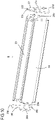
- FIG. 12 is an overall view of a state where the developing cartridge 4 is positioned in the apparatus main body of the image forming apparatus 100 when seen from a direction orthogonal to the axis of the developing roller 25.
- FIG. 1 is an enlarged view obtained by enlarging a side (left side) indicated by the arrows of the line A-A' of FIG. 12 , and illustrates the configuration in the vicinity of the first end portion member 37.
- FIG. 13 is an enlarged view obtained by enlarging the vicinity of a regulating portion 37f illustrated in FIG. 1 .
- the developing cartridge 4 is mounted to the apparatus main body of the image forming apparatus 100 in the direction of the arrow F to be positioned. As described above, when the developing cartridge 4 is mounted inside the apparatus main body to reach the back side in the mounting direction F, the developing cartridge 4 is raised to the image forming position, and the first positioning portion 37c and the first rotation-stopping portion 37d are engaged with the first main body-side positioning portion 99a and the first main body-side rotation-stopping portion 99b, respectively.
- a pressurizing portion 81 biasing member provided to the apparatus main body is brought into abutment against a force receiving portion 37e provided to the front-side side-surface of the first end portion member 37, thereby applying force to the force receiving portion 37e in the direction of the mounting direction F.
- the pressurizing portion 81 biases the force receiving portion 37e with biasing force from a spring (not shown), for example, so that the first end portion member 37 is fixed to the apparatus main body in the axial direction of the developing roller 25.
- the developing cartridge 4 is prevented from moving relative to the apparatus main body in the axial direction of the developing roller 25 when an image is formed or the developing cartridge 4 is conveyed while being mounted in the apparatus main body.
- the force receiving portion 37e is positioned on the lower side in the gravity direction of the first pivot center (hole) 37a with which the first boss 20a is engaged.
- the lower side corresponds to a first side (one side) in a direction (first direction) orthogonal to the rotation axis of the first end portion member 37.
- the regulating portion 37f which is a feature of the present embodiment, is provided on the upper side in the gravity direction of the first pivot center (hole) 37a with which the first boss 20a of the developing unit 39 is engaged.
- the upper side corresponds to a second side (another side) in a direction (first direction) orthogonal to the rotation axis of the first end portion member 37..
- the regulating portion 37f is provided on the back side of the first positioning portion 37c in the mounting direction F and is positioned on the back side in the mounting direction F (the outer side of the developing roller 25 in the axial direction) of a main body regulating surface 105 that is the side wall of the first main body-side positioning portion 99a on the back side in the mounting direction F, on the frame of the apparatus main body.
- the regulating portion 37f has a shape with a surface gradually inclined upward from the first positioning portion 37c in the mounting direction F, and faces the main body regulating surface 105 in a direction opposite to the mounting direction F.
- the regulating portion 37f has a portion that may be brought into abutment against the frame (first main body-side positioning portion 99a) of the apparatus main body at a position farther from the rotation axis of the first end portion member 37 than a position at which the first positioning portion 37c is brought into abutment against the frame.
- the regulating portion 37f may be brought into contact with the first main body-side positioning portion 99a before the first positioning portion 37c is brought into contact with the first main body-side positioning portion 99a.
- the first main body-side positioning portion 99a slides on the regulating portion 37f to be guided to the position at which the first main body-side positioning portion 99a is engaged with the first positioning portion 37c.
- the first end portion member 37 a portion on a side (one side) on which the force receiving portion 37e is provided and a portion on the opposite side (another side), which are defined with a boundary being the first pivot center (hole) 37a, try to move in a direction opposite to the direction (mounting direction F) in which the force receiving portion 37e receives force from the pressurizing portion 81.
- This movement is, however, regulated by the regulating portion 37f being brought into contact with the main body regulating surface 105, and the above-mentioned rotation of the first end portion member 37 is regulated.
- the first end portion member 37 can be prevented from being brought into contact with the developing unit 39, which means that the developing unit 39 can perform contact operation without the contact preventing the contact operation.
- the contact operation can be performed without being prevented, and hence the contact state between the developing roller 25 and the photosensitive drum 1 can be stabilized, that is, the image quality can be stabilized.
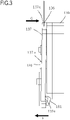
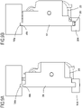
- FIG. 2 is a schematic enlarged view of the vicinity of a first end portion member 137 when seen from a direction orthogonal to the axis of a developing roller, under a state where a developing apparatus according to a comparative example is positioned in the apparatus main body of the image forming apparatus 100.
- the first end portion member 137 is attached to a developing unit 139 so that the first end portion member 137 and the developing unit 139 are movable relatively to each other.
- the first end portion member 137 and the developing unit 139 are supported as follows: a first pivot center (hole) 137a of the first end portion member 137 is supported with respect to a rotation boss 120 provided to the developing unit 139 in a relatively movable manner.
- a first positioning portion 137c provided to the first end portion member 137 is engaged with a first main body-side positioning portion 106 of the image forming apparatus to be positioned in the image forming apparatus.
- the first positioning portion 137c is arranged above the first pivot center 137a.
- the first end portion member 137 is fixed to the apparatus main body by being biased by a pressurizing portion 181 in the direction of the arrow F, which is the developing apparatus mounting direction.
- the pressurizing portion 181 of the apparatus main body biases a pressure receiving portion 137e of the first end portion member 137.
- the pressure receiving portion 137e is positioned below the first rotation center (hole) 137a with which the rotation boss 120 of the developing unit 139 is engaged.
- FIG. 3 is a schematic enlarged view illustrating a state where the first end portion member 137 rotates by being biased by the pressurizing portion 181 in the developing apparatus according to the comparative example.
- the first end portion member 137 rotates in the direction of the arrow G, with the fulcrum being the rotation boss 120. Consequently, the first end portion member 137 may be brought into contact with the developing unit 139. If the first end portion member 137 is brought into contact with the developing unit 139, the developing unit 139 is prevented from performing the contact operation of bringing the developing roller into contact with a photosensitive drum, and the developing roller supported by the developing unit 139 cannot be brought into contact with the photosensitive drum. As a result, image defects may occur.
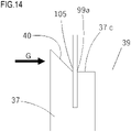
- the regulating portion 37f may be a first abutting portion 40 which is arranged toward the developing unit 39, and with which the main body regulating surface 105 is brought into contact when the developing cartridge 4 is raised to the image forming position.
- the regulating portion 37f of the present embodiment is not necessarily in contact with the main body regulating surface 105.
- the regulating portion 37f may face the main body regulating surface 105 with a slight gap therebetween and may be brought into contact with the main body regulating surface 105 only after the above-mentioned rotational moment is generated and the first end portion member 37 tries to change its posture.
- the first abutting portion 40 of Modified Example 1 is configured to be in contact with the main body regulating surface 105 in the first place, specifically, before the above-mentioned rotational moment is generated and the first end portion member 37 tries to change its posture. That is, in this configuration, the regulating portion functions as an abutting portion that is brought into abutment against the apparatus main body when the developing cartridge 4 is positioned in the image forming apparatus 100. With such a configuration, similarly to the effect that the present embodiment provides, the rotation of the first end portion member 37 can be prevented and the image quality can therefore be stabilized.
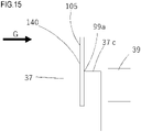
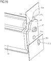
- the first abutting portion 40 illustrated in FIG. 14 which has an inclined shape, may be, according to another example not covered by the present invention, a first abutting portion 140 having a vertical surface as illustrated in FIG. 15 .
- the first abutting portion 140 is positioned above the first rotation center (hole) 37a with which the first boss 20a, which is the rotation fulcrum of the first end portion member 37, is engaged. Moreover, the first abutting portion 140 is provided to face the developing unit 39 and is in contact with the main body regulating surface 105. Further, the first positioning portion 37c arranged upward, which serves as a second abutting portion, is brought into contact with the first main body-side positioning portion 99a in the direction orthogonal to the axis of the developing roller 25 to fix the first end portion member 37 to the apparatus main body.
- the rotation of the first end portion member 37 is regulated because the first abutting portion 140 is brought into abutment against the main body regulating surface 105. Further, the first positioning portion 37c facing upward is brought into contact with the first main body-side positioning portion 99a in the direction orthogonal to the axis of the developing roller 25, and hence the first end portion member 37 is fixed to the apparatus main body in the direction orthogonal to the axis of the developing roller 25.
- the first end portion member 37 is prevented from rotating in the axial direction of the developing roller 25 by the first abutting portion 140, and is positioned in the direction orthogonal to the axis of the developing roller 25 by the first positioning portion 37c, which is the second abutting portion.
- the developing unit 39 is not prevented from performing the contact operation to the photosensitive drum 1 and the image quality can therefore be stabilized.
- the first abutting portion 40 and the first positioning portion 37c which is the second abutting portion, may be individually formed at separated positions. Also with such a configuration, the effect of preventing the rotation of the first end portion member 37 is obtained, and the image quality can be stabilized.
- the rotation regulating configuration for the end portion member described above may be applied to the second end portion member 38 in addition to the first end portion member 37.
- the developing cartridge 4 is exemplified as a cartridge to which the above-mentioned rotation regulating configuration is applied.
- the present invention is, however, not limited thereto, and the rotation regulating configuration may be applied to other cartridges as appropriate as long as they comprise the features of independent claim 1.
Landscapes
- Physics & Mathematics (AREA)
- General Physics & Mathematics (AREA)
- Engineering & Computer Science (AREA)
- Computer Vision & Pattern Recognition (AREA)
- Electrophotography Configuration And Component (AREA)
- Dry Development In Electrophotography (AREA)
Claims (7)
- Entwicklungsvorrichtung (4) mit:einem Rahmen (31), der so aufgebaut ist, dass er eine Entwicklungsrolle (25) drehbar stützt;einem ersten Endabschnittelement (37), das an einem Ende des Rahmens (31) in einer axialen Richtung der Entwicklungsrolle (25) so vorgesehen ist, dass es relativ zu dem Rahmen (31) um eine Drehachse drehbar ist, die parallel zu der axialen Richtung ist; undeinem zweiten Endabschnittelement (38), das an einem anderen Ende des Rahmens (31) in der axialen Richtung so vorgesehen ist, dass es relativ zu dem Rahmen (31) um die Drehachse drehbar ist, wobei das erste Endabschnittelement (37) und das zweite Endabschnittelement (38) unabhängig voneinander um die Drehachse drehen können,wobei die Entwicklungsvorrichtung (4) so aufgebaut ist, dass sie an einem Vorrichtungshauptkörper einer Bilderzeugungsvorrichtung (100) in der axialen Richtung entfernbar montierbar ist,wobei zumindest ein Endabschnittelement aus dem ersten Endabschnittelement (37) und dem zweiten Endabschnittelement (38) einen Kraftaufnahmeabschnitt (37e) und einen Regulierabschnitt (37f) hat, dadurch gekennzeichnet, dassder Kraftaufnahmeabschnitt (37e) an einer Seite des einen Endabschnittelementes in einer ersten Richtung vorgesehen ist, die senkrecht zu der Drehachse ist, und der Kraftaufnahmeabschnitt (37e) mit einer Kontaktfläche (37e) versehen ist, die sich in einer Richtung erstreckt, die eine Montagerichtung (F) der Entwicklungsvorrichtung kreuzt, und die so aufgebaut ist, dass sie eine Vorspannkraft von einem Vorspannelement (81) des Vorrichtungshauptkörpers empfängt durch einen Kontakt mit dem Vorspannelement (81) in der Montagerichtung (F), wenn die Entwicklungsvorrichtung (4) an dem Vorrichtungshauptkörper montiert wird,der Regulierabschnitt (37f) an der anderen Seite des einen Endabschnittelementes in der ersten Richtung vorgesehen ist und einen ersten Anlageabschnitt (40) hat, der eine geneigte Fläche ist, die zu sowohl der Drehachse als auch der ersten Richtung geneigt ist, und die so aufgebaut ist, dass sie an dem Vorrichtungshauptkörper in Anlage gebracht wird, um eine Bewegung der anderen Seite des einen Endabschnittelementes relativ zu dem Vorrichtungshauptkörper in einer Richtung (G) zu regulieren, die entgegengesetzt zu der Montagerichtung (F) ist, wobei ein Drehpunkt die Drehachse ist, undwenn die Entwicklungsvorrichtung (4) relativ zu dem Vorrichtungshauptkörper positioniert ist, der erste Anlageabschnitt (40) in Anlage an dem Vorrichtungshauptkörper in der Richtung (G) gebracht ist, während der Kraftaufnahmeabschnitt (37e) durch den Vorrichtungshauptkörper in der Montagerichtung (F) in Anlage ist.
- Entwicklungsvorrichtung (4) gemäß Anspruch 1, wobei der Regulierabschnitt (37f) so aufgebaut ist, dass er auch eine Bewegung des einen Endabschnittelementes relativ zu dem Vorrichtungshauptkörper in der Richtung reguliert, die senkrecht zu der Montagerichtung (F) ist.
- Entwicklungsvorrichtung gemäß einem der Ansprüche 1 oder 2,wobei die Entwicklungsvorrichtung des Weiteren einen zweiten Anlageabschnitt (37c) aufweist, der in Anlage an dem Vorrichtungshauptkörper in der Richtung gebracht wird, die senkrecht zu der Montagerichtung (F) ist, undwobei der Regulierabschnitt (37f) stromabwärtig des zweiten Anlageabschnittes (37c) in der Montagerichtung (F) vorgesehen ist.
- Entwicklungsvorrichtung (4) gemäß Anspruch 1, wobei der Regulierabschnitt (37f) an einer Position positioniert ist, die weiter von der Drehachse als eine Position entfernt ist, an der der zweite Anlageabschnitt (37c) positioniert ist.
- Entwicklungsvorrichtung (4) gemäß einem der Ansprüche 1 bis 4,wobei der Kraftaufnahmeabschnitt (37e) in einem unteren Teil in einer Schwerkraftrichtung in Bezug auf die Drehachse positioniert ist, undwobei der Regulierabschnitt (37f) in einem oberen Teil in Schwerkraftrichtung in Bezug auf die Drehachse positioniert ist.
- Bilderzeugungsvorrichtung (100) mit:der Entwicklungsvorrichtung (4) gemäß einem der Ansprüche 1 bis 5; undeinem Vorrichtungshauptkörper, an dem die Entwicklungsvorrichtung (4) entfernbar montiert ist.
- Bilderzeugungsvorrichtung (100) gemäß Anspruch 6,wobei der Vorrichtungshauptkörper ein Vorspannelement (81) und einen Positionierabschnitt (99a) aufweist,wobei das Vorspannelement (81) so aufgebaut ist, dass es eine Vorspannkraft auf den Kraftaufnahmeabschnitt der Entwicklungsvorrichtung in der Montagerichtung (F) aufbringt,wobei der Positionierabschnitt (99a) so aufgebaut ist, dass er mit dem einen Endabschnittelement an einer Seite in Kontakt gebracht wird, die zu dem Vorspannelement (81) in der ersten Richtung entgegengesetzt ist, wobei die Seite mit einer Grenze definiert ist, die die Drehachse ist, undwobei der Regulierabschnitt (37f) der Entwicklungsvorrichtung (4) so aufgebaut ist, dass er mit dem Positionierabschnitt (99a) in der Richtung in Kontakt gebracht wird, die zu der Montagerichtung (F) entgegengesetzt ist.
Applications Claiming Priority (1)
| Application Number | Priority Date | Filing Date | Title |
|---|---|---|---|
| JP2017190415A JP6921699B2 (ja) | 2017-09-29 | 2017-09-29 | 現像装置及び画像形成装置 |
Publications (2)
| Publication Number | Publication Date |
|---|---|
| EP3462243A1 EP3462243A1 (de) | 2019-04-03 |
| EP3462243B1 true EP3462243B1 (de) | 2022-04-27 |
Family
ID=63683734
Family Applications (1)
| Application Number | Title | Priority Date | Filing Date |
|---|---|---|---|
| EP18196533.6A Active EP3462243B1 (de) | 2017-09-29 | 2018-09-25 | Entwicklungsvorrichtung und bilderzeugungsvorrichtung |
Country Status (8)
| Country | Link |
|---|---|
| US (1) | US10670986B2 (de) |
| EP (1) | EP3462243B1 (de) |
| JP (1) | JP6921699B2 (de) |
| KR (1) | KR102312589B1 (de) |
| CN (1) | CN109581838B (de) |
| PH (1) | PH12018000287A1 (de) |
| RU (1) | RU2705749C1 (de) |
| SG (1) | SG10201808506XA (de) |
Family Cites Families (19)
| Publication number | Priority date | Publication date | Assignee | Title |
|---|---|---|---|---|
| JP2003228234A (ja) | 2002-02-01 | 2003-08-15 | Canon Inc | プロセスカートリッジ及び画像形成装置 |
| JP4006414B2 (ja) * | 2004-06-02 | 2007-11-14 | キヤノン株式会社 | 現像装置及びプロセスカートリッジ |
| JP4385295B2 (ja) | 2004-07-29 | 2009-12-16 | ブラザー工業株式会社 | 現像装置、プロセスカートリッジおよび画像形成装置 |
| JP4498407B2 (ja) * | 2006-12-22 | 2010-07-07 | キヤノン株式会社 | プロセスカートリッジ、電子写真画像形成装置、及び、電子写真感光体ドラムユニット |
| JP4968957B2 (ja) * | 2008-03-31 | 2012-07-04 | キヤノン株式会社 | 枠体ユニット、現像装置及びプロセスカートリッジ、並びに、枠体ユニット、現像装置及びプロセスカートリッジの製造方法 |
| JP5127565B2 (ja) * | 2008-05-23 | 2013-01-23 | キヤノン株式会社 | カートリッジ及び画像形成装置 |
| JP5004870B2 (ja) * | 2008-05-23 | 2012-08-22 | キヤノン株式会社 | プロセスカートリッジ、及び電子写真画像形成装置 |
| JP4701266B2 (ja) * | 2008-05-27 | 2011-06-15 | キヤノン株式会社 | プロセスカートリッジ及び電子写真画像形成装置 |
| JP5288900B2 (ja) * | 2008-06-20 | 2013-09-11 | キヤノン株式会社 | プロセスカートリッジ及び電子写真画像形成装置 |
| JP2011242757A (ja) | 2010-04-20 | 2011-12-01 | Canon Inc | 規制部材、クリーニング部材、現像装置、クリーニング装置、プロセスカートリッジ、及び画像形成装置 |
| JP2012118506A (ja) | 2010-11-10 | 2012-06-21 | Canon Inc | プロセスカートリッジ及び現像装置 |
| JP5935391B2 (ja) | 2012-02-29 | 2016-06-15 | ブラザー工業株式会社 | 画像形成装置 |
| JP6039247B2 (ja) * | 2012-06-04 | 2016-12-07 | キヤノン株式会社 | 現像装置、プロセスカートリッジ、画像形成装置 |
| JP6184311B2 (ja) * | 2012-12-14 | 2017-08-23 | キヤノン株式会社 | プロセスカートリッジ及び画像形成装置 |
| JP6402898B2 (ja) * | 2014-06-09 | 2018-10-10 | 株式会社リコー | ベルト装置、ベルト定着装置及び画像形成装置 |
| US10067461B2 (en) | 2016-02-29 | 2018-09-04 | Canon Kabushiki Kaisha | Developing cartridge with a restricted portion that contacts a restricting portion of an image forming apparatus |
| JP6465906B2 (ja) * | 2016-02-29 | 2019-02-06 | キヤノン株式会社 | 現像装置、プロセスカートリッジおよび画像形成装置 |
| JP7076945B2 (ja) * | 2016-03-22 | 2022-05-30 | キヤノン株式会社 | 現像装置及び画像形成装置 |
| US10241438B2 (en) | 2016-03-22 | 2019-03-26 | Canon Kabushiki Kaisha | Developing device having a developing unit that is pivotally supported about the axis of a shaft, and image forming apparatus |
-
2017
- 2017-09-29 JP JP2017190415A patent/JP6921699B2/ja active Active
-
2018
- 2018-09-21 KR KR1020180113501A patent/KR102312589B1/ko active Active
- 2018-09-24 RU RU2018133605A patent/RU2705749C1/ru active
- 2018-09-24 US US16/139,528 patent/US10670986B2/en active Active
- 2018-09-25 EP EP18196533.6A patent/EP3462243B1/de active Active
- 2018-09-27 SG SG10201808506XA patent/SG10201808506XA/en unknown
- 2018-09-28 CN CN201811134622.8A patent/CN109581838B/zh active Active
- 2018-09-28 PH PH12018000287A patent/PH12018000287A1/en unknown
Also Published As
| Publication number | Publication date |
|---|---|
| SG10201808506XA (en) | 2019-04-29 |
| JP6921699B2 (ja) | 2021-08-18 |
| PH12018000287A1 (en) | 2019-04-15 |
| US20190101846A1 (en) | 2019-04-04 |
| EP3462243A1 (de) | 2019-04-03 |
| RU2705749C1 (ru) | 2019-11-11 |
| KR102312589B1 (ko) | 2021-10-15 |
| CN109581838A (zh) | 2019-04-05 |
| JP2019066609A (ja) | 2019-04-25 |
| KR20190038360A (ko) | 2019-04-08 |
| CN109581838B (zh) | 2022-04-19 |
| US10670986B2 (en) | 2020-06-02 |
Similar Documents
| Publication | Publication Date | Title |
|---|---|---|
| US9354543B2 (en) | Developing device and image forming device having the same | |
| KR102197113B1 (ko) | 화상형성장치의 본체에 장착가능한 카트리지 | |
| US8903273B2 (en) | Image forming device having retaining member that can be pulled out therefrom | |
| EP3211482A1 (de) | Entwicklungskartusche und bilderzeugungsvorrichtung | |
| US10139774B2 (en) | Developing device and image forming apparatus | |
| KR20210053866A (ko) | 화상형성장치의 본체에 장착가능한 현상 카트리지 | |
| US11188021B2 (en) | Cartridge including an image bearing member and developer bearing member that can be easily separated | |
| US20150346679A1 (en) | Image forming apparatus | |
| US20160062308A1 (en) | Image forming device having retaining member that can be pulled out therefrom | |
| US7483648B2 (en) | Process cartridge and image forming apparatus using the same | |
| US10241438B2 (en) | Developing device having a developing unit that is pivotally supported about the axis of a shaft, and image forming apparatus | |
| JP6137786B2 (ja) | 現像装置、プロセスカートリッジ、画像形成装置 | |
| US20130121721A1 (en) | Developer conveyance apparatus developing apparatus and process cartridge | |
| EP3835872B1 (de) | Prozesskartusche, entwicklungsvorrichtung und bilderzeugungsvorrichtung | |
| JP6938166B2 (ja) | 画像形成装置 | |
| US20240345536A1 (en) | Cartridge including photosensitive drum and developing roller that can be easily separated | |
| EP3462243B1 (de) | Entwicklungsvorrichtung und bilderzeugungsvorrichtung | |
| JP6942011B2 (ja) | 帯電ローラ軸受保持機構 | |
| JP2017156744A (ja) | 現像カートリッジ、画像形成装置 | |
| JP6440011B2 (ja) | 現像装置、画像形成装置、及びプロセスカートリッジ |
Legal Events
| Date | Code | Title | Description |
|---|---|---|---|
| PUAI | Public reference made under article 153(3) epc to a published international application that has entered the european phase |
Free format text: ORIGINAL CODE: 0009012 |
|
| STAA | Information on the status of an ep patent application or granted ep patent |
Free format text: STATUS: THE APPLICATION HAS BEEN PUBLISHED |
|
| AK | Designated contracting states |
Kind code of ref document: A1 Designated state(s): AL AT BE BG CH CY CZ DE DK EE ES FI FR GB GR HR HU IE IS IT LI LT LU LV MC MK MT NL NO PL PT RO RS SE SI SK SM TR |
|
| AX | Request for extension of the european patent |
Extension state: BA ME |
|
| STAA | Information on the status of an ep patent application or granted ep patent |
Free format text: STATUS: REQUEST FOR EXAMINATION WAS MADE |
|
| 17P | Request for examination filed |
Effective date: 20191004 |
|
| RBV | Designated contracting states (corrected) |
Designated state(s): AL AT BE BG CH CY CZ DE DK EE ES FI FR GB GR HR HU IE IS IT LI LT LU LV MC MK MT NL NO PL PT RO RS SE SI SK SM TR |
|
| STAA | Information on the status of an ep patent application or granted ep patent |
Free format text: STATUS: EXAMINATION IS IN PROGRESS |
|
| 17Q | First examination report despatched |
Effective date: 20200331 |
|
| GRAP | Despatch of communication of intention to grant a patent |
Free format text: ORIGINAL CODE: EPIDOSNIGR1 |
|
| STAA | Information on the status of an ep patent application or granted ep patent |
Free format text: STATUS: GRANT OF PATENT IS INTENDED |
|
| RIC1 | Information provided on ipc code assigned before grant |
Ipc: G03G 21/18 20060101ALN20211028BHEP Ipc: G03G 21/16 20060101ALI20211028BHEP Ipc: G03G 15/08 20060101AFI20211028BHEP |
|
| INTG | Intention to grant announced |
Effective date: 20211122 |
|
| GRAS | Grant fee paid |
Free format text: ORIGINAL CODE: EPIDOSNIGR3 |
|
| GRAA | (expected) grant |
Free format text: ORIGINAL CODE: 0009210 |
|
| STAA | Information on the status of an ep patent application or granted ep patent |
Free format text: STATUS: THE PATENT HAS BEEN GRANTED |
|
| AK | Designated contracting states |
Kind code of ref document: B1 Designated state(s): AL AT BE BG CH CY CZ DE DK EE ES FI FR GB GR HR HU IE IS IT LI LT LU LV MC MK MT NL NO PL PT RO RS SE SI SK SM TR |
|
| REG | Reference to a national code |
Ref country code: GB Ref legal event code: FG4D |
|
| REG | Reference to a national code |
Ref country code: CH Ref legal event code: EP |
|
| REG | Reference to a national code |
Ref country code: DE Ref legal event code: R096 Ref document number: 602018034432 Country of ref document: DE |
|
| REG | Reference to a national code |
Ref country code: AT Ref legal event code: REF Ref document number: 1487408 Country of ref document: AT Kind code of ref document: T Effective date: 20220515 |
|
| REG | Reference to a national code |
Ref country code: IE Ref legal event code: FG4D |
|
| REG | Reference to a national code |
Ref country code: LT Ref legal event code: MG9D |
|
| REG | Reference to a national code |
Ref country code: NL Ref legal event code: MP Effective date: 20220427 |
|
| REG | Reference to a national code |
Ref country code: AT Ref legal event code: MK05 Ref document number: 1487408 Country of ref document: AT Kind code of ref document: T Effective date: 20220427 |
|
| PG25 | Lapsed in a contracting state [announced via postgrant information from national office to epo] |
Ref country code: NL Free format text: LAPSE BECAUSE OF FAILURE TO SUBMIT A TRANSLATION OF THE DESCRIPTION OR TO PAY THE FEE WITHIN THE PRESCRIBED TIME-LIMIT Effective date: 20220427 |
|
| PG25 | Lapsed in a contracting state [announced via postgrant information from national office to epo] |
Ref country code: SE Free format text: LAPSE BECAUSE OF FAILURE TO SUBMIT A TRANSLATION OF THE DESCRIPTION OR TO PAY THE FEE WITHIN THE PRESCRIBED TIME-LIMIT Effective date: 20220427 Ref country code: PT Free format text: LAPSE BECAUSE OF FAILURE TO SUBMIT A TRANSLATION OF THE DESCRIPTION OR TO PAY THE FEE WITHIN THE PRESCRIBED TIME-LIMIT Effective date: 20220829 Ref country code: NO Free format text: LAPSE BECAUSE OF FAILURE TO SUBMIT A TRANSLATION OF THE DESCRIPTION OR TO PAY THE FEE WITHIN THE PRESCRIBED TIME-LIMIT Effective date: 20220727 Ref country code: LT Free format text: LAPSE BECAUSE OF FAILURE TO SUBMIT A TRANSLATION OF THE DESCRIPTION OR TO PAY THE FEE WITHIN THE PRESCRIBED TIME-LIMIT Effective date: 20220427 Ref country code: HR Free format text: LAPSE BECAUSE OF FAILURE TO SUBMIT A TRANSLATION OF THE DESCRIPTION OR TO PAY THE FEE WITHIN THE PRESCRIBED TIME-LIMIT Effective date: 20220427 Ref country code: GR Free format text: LAPSE BECAUSE OF FAILURE TO SUBMIT A TRANSLATION OF THE DESCRIPTION OR TO PAY THE FEE WITHIN THE PRESCRIBED TIME-LIMIT Effective date: 20220728 Ref country code: FI Free format text: LAPSE BECAUSE OF FAILURE TO SUBMIT A TRANSLATION OF THE DESCRIPTION OR TO PAY THE FEE WITHIN THE PRESCRIBED TIME-LIMIT Effective date: 20220427 Ref country code: ES Free format text: LAPSE BECAUSE OF FAILURE TO SUBMIT A TRANSLATION OF THE DESCRIPTION OR TO PAY THE FEE WITHIN THE PRESCRIBED TIME-LIMIT Effective date: 20220427 Ref country code: BG Free format text: LAPSE BECAUSE OF FAILURE TO SUBMIT A TRANSLATION OF THE DESCRIPTION OR TO PAY THE FEE WITHIN THE PRESCRIBED TIME-LIMIT Effective date: 20220727 Ref country code: AT Free format text: LAPSE BECAUSE OF FAILURE TO SUBMIT A TRANSLATION OF THE DESCRIPTION OR TO PAY THE FEE WITHIN THE PRESCRIBED TIME-LIMIT Effective date: 20220427 |
|
| PG25 | Lapsed in a contracting state [announced via postgrant information from national office to epo] |
Ref country code: RS Free format text: LAPSE BECAUSE OF FAILURE TO SUBMIT A TRANSLATION OF THE DESCRIPTION OR TO PAY THE FEE WITHIN THE PRESCRIBED TIME-LIMIT Effective date: 20220427 Ref country code: PL Free format text: LAPSE BECAUSE OF FAILURE TO SUBMIT A TRANSLATION OF THE DESCRIPTION OR TO PAY THE FEE WITHIN THE PRESCRIBED TIME-LIMIT Effective date: 20220427 Ref country code: LV Free format text: LAPSE BECAUSE OF FAILURE TO SUBMIT A TRANSLATION OF THE DESCRIPTION OR TO PAY THE FEE WITHIN THE PRESCRIBED TIME-LIMIT Effective date: 20220427 Ref country code: IS Free format text: LAPSE BECAUSE OF FAILURE TO SUBMIT A TRANSLATION OF THE DESCRIPTION OR TO PAY THE FEE WITHIN THE PRESCRIBED TIME-LIMIT Effective date: 20220827 |
|
| REG | Reference to a national code |
Ref country code: DE Ref legal event code: R097 Ref document number: 602018034432 Country of ref document: DE |
|
| PG25 | Lapsed in a contracting state [announced via postgrant information from national office to epo] |
Ref country code: SM Free format text: LAPSE BECAUSE OF FAILURE TO SUBMIT A TRANSLATION OF THE DESCRIPTION OR TO PAY THE FEE WITHIN THE PRESCRIBED TIME-LIMIT Effective date: 20220427 Ref country code: SK Free format text: LAPSE BECAUSE OF FAILURE TO SUBMIT A TRANSLATION OF THE DESCRIPTION OR TO PAY THE FEE WITHIN THE PRESCRIBED TIME-LIMIT Effective date: 20220427 Ref country code: RO Free format text: LAPSE BECAUSE OF FAILURE TO SUBMIT A TRANSLATION OF THE DESCRIPTION OR TO PAY THE FEE WITHIN THE PRESCRIBED TIME-LIMIT Effective date: 20220427 Ref country code: EE Free format text: LAPSE BECAUSE OF FAILURE TO SUBMIT A TRANSLATION OF THE DESCRIPTION OR TO PAY THE FEE WITHIN THE PRESCRIBED TIME-LIMIT Effective date: 20220427 Ref country code: DK Free format text: LAPSE BECAUSE OF FAILURE TO SUBMIT A TRANSLATION OF THE DESCRIPTION OR TO PAY THE FEE WITHIN THE PRESCRIBED TIME-LIMIT Effective date: 20220427 Ref country code: CZ Free format text: LAPSE BECAUSE OF FAILURE TO SUBMIT A TRANSLATION OF THE DESCRIPTION OR TO PAY THE FEE WITHIN THE PRESCRIBED TIME-LIMIT Effective date: 20220427 |
|
| PLBE | No opposition filed within time limit |
Free format text: ORIGINAL CODE: 0009261 |
|
| STAA | Information on the status of an ep patent application or granted ep patent |
Free format text: STATUS: NO OPPOSITION FILED WITHIN TIME LIMIT |
|
| PG25 | Lapsed in a contracting state [announced via postgrant information from national office to epo] |
Ref country code: AL Free format text: LAPSE BECAUSE OF FAILURE TO SUBMIT A TRANSLATION OF THE DESCRIPTION OR TO PAY THE FEE WITHIN THE PRESCRIBED TIME-LIMIT Effective date: 20220427 |
|
| 26N | No opposition filed |
Effective date: 20230130 |
|
| PG25 | Lapsed in a contracting state [announced via postgrant information from national office to epo] |
Ref country code: MC Free format text: LAPSE BECAUSE OF FAILURE TO SUBMIT A TRANSLATION OF THE DESCRIPTION OR TO PAY THE FEE WITHIN THE PRESCRIBED TIME-LIMIT Effective date: 20220427 |
|
| REG | Reference to a national code |
Ref country code: CH Ref legal event code: PL |
|
| REG | Reference to a national code |
Ref country code: BE Ref legal event code: MM Effective date: 20220930 |
|
| PG25 | Lapsed in a contracting state [announced via postgrant information from national office to epo] |
Ref country code: SI Free format text: LAPSE BECAUSE OF FAILURE TO SUBMIT A TRANSLATION OF THE DESCRIPTION OR TO PAY THE FEE WITHIN THE PRESCRIBED TIME-LIMIT Effective date: 20220427 |
|
| PG25 | Lapsed in a contracting state [announced via postgrant information from national office to epo] |
Ref country code: LU Free format text: LAPSE BECAUSE OF NON-PAYMENT OF DUE FEES Effective date: 20220925 |
|
| PG25 | Lapsed in a contracting state [announced via postgrant information from national office to epo] |
Ref country code: LI Free format text: LAPSE BECAUSE OF NON-PAYMENT OF DUE FEES Effective date: 20220930 Ref country code: IE Free format text: LAPSE BECAUSE OF NON-PAYMENT OF DUE FEES Effective date: 20220925 Ref country code: CH Free format text: LAPSE BECAUSE OF NON-PAYMENT OF DUE FEES Effective date: 20220930 |
|
| PG25 | Lapsed in a contracting state [announced via postgrant information from national office to epo] |
Ref country code: BE Free format text: LAPSE BECAUSE OF NON-PAYMENT OF DUE FEES Effective date: 20220930 |
|
| PG25 | Lapsed in a contracting state [announced via postgrant information from national office to epo] |
Ref country code: IT Free format text: LAPSE BECAUSE OF FAILURE TO SUBMIT A TRANSLATION OF THE DESCRIPTION OR TO PAY THE FEE WITHIN THE PRESCRIBED TIME-LIMIT Effective date: 20220427 |
|
| PG25 | Lapsed in a contracting state [announced via postgrant information from national office to epo] |
Ref country code: HU Free format text: LAPSE BECAUSE OF FAILURE TO SUBMIT A TRANSLATION OF THE DESCRIPTION OR TO PAY THE FEE WITHIN THE PRESCRIBED TIME-LIMIT; INVALID AB INITIO Effective date: 20180925 |
|
| PG25 | Lapsed in a contracting state [announced via postgrant information from national office to epo] |
Ref country code: CY Free format text: LAPSE BECAUSE OF FAILURE TO SUBMIT A TRANSLATION OF THE DESCRIPTION OR TO PAY THE FEE WITHIN THE PRESCRIBED TIME-LIMIT Effective date: 20220427 |
|
| PG25 | Lapsed in a contracting state [announced via postgrant information from national office to epo] |
Ref country code: MK Free format text: LAPSE BECAUSE OF FAILURE TO SUBMIT A TRANSLATION OF THE DESCRIPTION OR TO PAY THE FEE WITHIN THE PRESCRIBED TIME-LIMIT Effective date: 20220427 |
|
| PG25 | Lapsed in a contracting state [announced via postgrant information from national office to epo] |
Ref country code: MT Free format text: LAPSE BECAUSE OF FAILURE TO SUBMIT A TRANSLATION OF THE DESCRIPTION OR TO PAY THE FEE WITHIN THE PRESCRIBED TIME-LIMIT Effective date: 20220427 |
|
| PG25 | Lapsed in a contracting state [announced via postgrant information from national office to epo] |
Ref country code: BG Free format text: LAPSE BECAUSE OF FAILURE TO SUBMIT A TRANSLATION OF THE DESCRIPTION OR TO PAY THE FEE WITHIN THE PRESCRIBED TIME-LIMIT Effective date: 20220427 |
|
| PG25 | Lapsed in a contracting state [announced via postgrant information from national office to epo] |
Ref country code: BG Free format text: LAPSE BECAUSE OF FAILURE TO SUBMIT A TRANSLATION OF THE DESCRIPTION OR TO PAY THE FEE WITHIN THE PRESCRIBED TIME-LIMIT Effective date: 20220427 |
|
| PGFP | Annual fee paid to national office [announced via postgrant information from national office to epo] |
Ref country code: DE Payment date: 20250820 Year of fee payment: 8 |
|
| PGFP | Annual fee paid to national office [announced via postgrant information from national office to epo] |
Ref country code: GB Payment date: 20250822 Year of fee payment: 8 |
|
| PGFP | Annual fee paid to national office [announced via postgrant information from national office to epo] |
Ref country code: FR Payment date: 20250820 Year of fee payment: 8 |
|
| PG25 | Lapsed in a contracting state [announced via postgrant information from national office to epo] |
Ref country code: TR Free format text: LAPSE BECAUSE OF FAILURE TO SUBMIT A TRANSLATION OF THE DESCRIPTION OR TO PAY THE FEE WITHIN THE PRESCRIBED TIME-LIMIT Effective date: 20220427 |