EP3222317B1 - Vascular occlusion balloon catheter - Google Patents
Vascular occlusion balloon catheter Download PDFInfo
- Publication number
- EP3222317B1 EP3222317B1 EP17162665.8A EP17162665A EP3222317B1 EP 3222317 B1 EP3222317 B1 EP 3222317B1 EP 17162665 A EP17162665 A EP 17162665A EP 3222317 B1 EP3222317 B1 EP 3222317B1
- Authority
- EP
- European Patent Office
- Prior art keywords
- distal end
- balloon catheter
- balloon
- air discharge
- discharge passage
- Prior art date
- Legal status (The legal status is an assumption and is not a legal conclusion. Google has not performed a legal analysis and makes no representation as to the accuracy of the status listed.)
- Active
Links
Images


Classifications
-
- A—HUMAN NECESSITIES
- A61—MEDICAL OR VETERINARY SCIENCE; HYGIENE
- A61M—DEVICES FOR INTRODUCING MEDIA INTO, OR ONTO, THE BODY; DEVICES FOR TRANSDUCING BODY MEDIA OR FOR TAKING MEDIA FROM THE BODY; DEVICES FOR PRODUCING OR ENDING SLEEP OR STUPOR
- A61M25/00—Catheters; Hollow probes
- A61M25/10—Balloon catheters
- A61M25/104—Balloon catheters used for angioplasty
-
- A—HUMAN NECESSITIES
- A61—MEDICAL OR VETERINARY SCIENCE; HYGIENE
- A61B—DIAGNOSIS; SURGERY; IDENTIFICATION
- A61B17/00—Surgical instruments, devices or methods
- A61B17/12—Surgical instruments, devices or methods for ligaturing or otherwise compressing tubular parts of the body, e.g. blood vessels or umbilical cord
- A61B17/12022—Occluding by internal devices, e.g. balloons or releasable wires
- A61B17/12027—Type of occlusion
- A61B17/1204—Type of occlusion temporary occlusion
-
- A—HUMAN NECESSITIES
- A61—MEDICAL OR VETERINARY SCIENCE; HYGIENE
- A61B—DIAGNOSIS; SURGERY; IDENTIFICATION
- A61B17/00—Surgical instruments, devices or methods
- A61B17/12—Surgical instruments, devices or methods for ligaturing or otherwise compressing tubular parts of the body, e.g. blood vessels or umbilical cord
- A61B17/12022—Occluding by internal devices, e.g. balloons or releasable wires
- A61B17/12099—Occluding by internal devices, e.g. balloons or releasable wires characterised by the location of the occluder
- A61B17/12109—Occluding by internal devices, e.g. balloons or releasable wires characterised by the location of the occluder in a blood vessel
-
- A—HUMAN NECESSITIES
- A61—MEDICAL OR VETERINARY SCIENCE; HYGIENE
- A61B—DIAGNOSIS; SURGERY; IDENTIFICATION
- A61B17/00—Surgical instruments, devices or methods
- A61B17/12—Surgical instruments, devices or methods for ligaturing or otherwise compressing tubular parts of the body, e.g. blood vessels or umbilical cord
- A61B17/12022—Occluding by internal devices, e.g. balloons or releasable wires
- A61B17/12131—Occluding by internal devices, e.g. balloons or releasable wires characterised by the type of occluding device
- A61B17/12136—Balloons
-
- A—HUMAN NECESSITIES
- A61—MEDICAL OR VETERINARY SCIENCE; HYGIENE
- A61M—DEVICES FOR INTRODUCING MEDIA INTO, OR ONTO, THE BODY; DEVICES FOR TRANSDUCING BODY MEDIA OR FOR TAKING MEDIA FROM THE BODY; DEVICES FOR PRODUCING OR ENDING SLEEP OR STUPOR
- A61M25/00—Catheters; Hollow probes
- A61M25/01—Introducing, guiding, advancing, emplacing or holding catheters
- A61M25/0102—Insertion or introduction using an inner stiffening member, e.g. stylet or push-rod
-
- A—HUMAN NECESSITIES
- A61—MEDICAL OR VETERINARY SCIENCE; HYGIENE
- A61M—DEVICES FOR INTRODUCING MEDIA INTO, OR ONTO, THE BODY; DEVICES FOR TRANSDUCING BODY MEDIA OR FOR TAKING MEDIA FROM THE BODY; DEVICES FOR PRODUCING OR ENDING SLEEP OR STUPOR
- A61M5/00—Devices for bringing media into the body in a subcutaneous, intra-vascular or intramuscular way; Accessories therefor, e.g. filling or cleaning devices, arm-rests
- A61M5/36—Devices for bringing media into the body in a subcutaneous, intra-vascular or intramuscular way; Accessories therefor, e.g. filling or cleaning devices, arm-rests with means for eliminating or preventing injection or infusion of air into body
-
- A—HUMAN NECESSITIES
- A61—MEDICAL OR VETERINARY SCIENCE; HYGIENE
- A61M—DEVICES FOR INTRODUCING MEDIA INTO, OR ONTO, THE BODY; DEVICES FOR TRANSDUCING BODY MEDIA OR FOR TAKING MEDIA FROM THE BODY; DEVICES FOR PRODUCING OR ENDING SLEEP OR STUPOR
- A61M25/00—Catheters; Hollow probes
- A61M25/10—Balloon catheters
- A61M2025/1043—Balloon catheters with special features or adapted for special applications
- A61M2025/1052—Balloon catheters with special features or adapted for special applications for temporarily occluding a vessel for isolating a sector
-
- A—HUMAN NECESSITIES
- A61—MEDICAL OR VETERINARY SCIENCE; HYGIENE
- A61M—DEVICES FOR INTRODUCING MEDIA INTO, OR ONTO, THE BODY; DEVICES FOR TRANSDUCING BODY MEDIA OR FOR TAKING MEDIA FROM THE BODY; DEVICES FOR PRODUCING OR ENDING SLEEP OR STUPOR
- A61M25/00—Catheters; Hollow probes
- A61M25/10—Balloon catheters
- A61M2025/1043—Balloon catheters with special features or adapted for special applications
- A61M2025/1077—Balloon catheters with special features or adapted for special applications having a system for expelling the air out of the balloon before inflation and use
-
- A—HUMAN NECESSITIES
- A61—MEDICAL OR VETERINARY SCIENCE; HYGIENE
- A61M—DEVICES FOR INTRODUCING MEDIA INTO, OR ONTO, THE BODY; DEVICES FOR TRANSDUCING BODY MEDIA OR FOR TAKING MEDIA FROM THE BODY; DEVICES FOR PRODUCING OR ENDING SLEEP OR STUPOR
- A61M25/00—Catheters; Hollow probes
- A61M25/10—Balloon catheters
- A61M2025/1043—Balloon catheters with special features or adapted for special applications
- A61M2025/1079—Balloon catheters with special features or adapted for special applications having radio-opaque markers in the region of the balloon
-
- A—HUMAN NECESSITIES
- A61—MEDICAL OR VETERINARY SCIENCE; HYGIENE
- A61M—DEVICES FOR INTRODUCING MEDIA INTO, OR ONTO, THE BODY; DEVICES FOR TRANSDUCING BODY MEDIA OR FOR TAKING MEDIA FROM THE BODY; DEVICES FOR PRODUCING OR ENDING SLEEP OR STUPOR
- A61M25/00—Catheters; Hollow probes
- A61M25/10—Balloon catheters
- A61M2025/1043—Balloon catheters with special features or adapted for special applications
- A61M2025/1081—Balloon catheters with special features or adapted for special applications having sheaths or the like for covering the balloon but not forming a permanent part of the balloon, e.g. retractable, dissolvable or tearable sheaths
-
- A—HUMAN NECESSITIES
- A61—MEDICAL OR VETERINARY SCIENCE; HYGIENE
- A61M—DEVICES FOR INTRODUCING MEDIA INTO, OR ONTO, THE BODY; DEVICES FOR TRANSDUCING BODY MEDIA OR FOR TAKING MEDIA FROM THE BODY; DEVICES FOR PRODUCING OR ENDING SLEEP OR STUPOR
- A61M25/00—Catheters; Hollow probes
- A61M25/0043—Catheters; Hollow probes characterised by structural features
- A61M25/005—Catheters; Hollow probes characterised by structural features with embedded materials for reinforcement, e.g. wires, coils, braids
-
- A—HUMAN NECESSITIES
- A61—MEDICAL OR VETERINARY SCIENCE; HYGIENE
- A61M—DEVICES FOR INTRODUCING MEDIA INTO, OR ONTO, THE BODY; DEVICES FOR TRANSDUCING BODY MEDIA OR FOR TAKING MEDIA FROM THE BODY; DEVICES FOR PRODUCING OR ENDING SLEEP OR STUPOR
- A61M25/00—Catheters; Hollow probes
- A61M25/10—Balloon catheters
- A61M25/1006—Balloons formed between concentric tubes
Definitions
- the present invention relates to a vascular occlusion balloon catheter to be inserted into a blood vessel.
- the vascular occlusion balloon catheter is used to perform angiography, inject a liquid medicine such as a chemotherapeutic agent into a blood vessel, and perform vascular embolization.
- the balloon catheter disclosed in U.S.P. 4638805 [Japanese Examined Patent Application Publication No. 03(1991)-56067 ] (Patent document 1) has the apparatus for discharging air from the inside of the balloon and restraining the liquid from escaping from the balloon.
- the apparatus for discharging the air from the inside of the balloon and restraining the liquid from escaping from the balloon there is disclosed the very small passage 21 extended from the inside of the balloon to the periphery of the distal end of the balloon catheter 11.
- the wire used to form the small passage has the diameter not more than 0.001 inches (0.0254mm), for example, 0.0005 inches (0.0127mm).
- the wire having the diameter of 0.001 inches (0.0254mm) has the sectional area of about 506 ⁇ m 2 .
- the wire having the diameter of 0.0005 inches (0.0127mm) has the sectional area of about 126 ⁇ m 2 .
- the present applicant proposed the balloon catheter as disclosed in Japanese Patent Application Laid-Open Publication No. 2005-103120 (Patent document 2).
- the balloon catheter of the patent document 2 is used after the priming operation (air inside balloon and balloon lumen is replaced with liquid) is performed by using the liquid containing the imaging agent for the balloon and the balloon lumen.
- the balloon catheter 1 of the patent document 2 has the double tube-structured catheter body 3 having the inner tube 9 and the outer tube 21.
- the balloon 7 is mounted on the catheter body at its distal end portion.
- the injection liquid passage 23 formed between the inner tube and the outer tube communicates with the inside of the balloon through the distal end opening 22 of the outer tube.
- the purging hole 24 formed on the outer tube is closed with the purging hole cover 33. In purging air inside the balloon and the lumen, the purging hole cover is elastically displaced outward in the radial direction of the catheter to discharge the air and prevents the air from flowing in the opposite direction.
- each of the balloon catheters of the patent documents 1 and 2 has the purging hole as described above, the priming operation can be accomplished. But in each of the balloon catheters of the patent documents 1 and 2, it takes time to perform the priming operation. In addition, although the priming operation may be easily performed, the liquid injected into the balloon flows out during the use of the balloon catheters, which leads to defective maintenance of the embolized state of a blood vessel.
- a vascular occlusion balloon catheter having a balloon which can be expanded by a liquid injected thereinto and an air discharge passage which communicates with an inside of the balloon and has is open at a distal end portion of the balloon catheter intended to allow a priming operation of replacing air inside the balloon with a liquid to be reliably and satisfactorily performed, allow a liquid injected into the balloon to flow out in a small amount from the balloon when the balloon catheter is used, and allow the balloon to keep a blood vessel-occluded state for a predetermined period of time.
- a vascular occlusion balloon catheter comprising a vascular occlusion balloon and a shaft part having a main lumen and a balloon expanding lumen
- said vascular occlusion balloon catheter has an air discharge passage
- said air discharge passage has a distal end opening located at a position distal from said vascular occlusion balloon and a proximal end communicating with an inner portion of said vascular occlusion balloon
- said distal end opening of said air discharge passage is positioned inside a portion disposed proximally from a distal end of said vascular occlusion balloon catheter
- said air discharge passage communicates with said main lumen at said distal end opening of said air discharge passage
- an area of a cross section of said air discharge passage orthogonal to an axial direction of said vascular occlusion balloon catheter is set to 200 ⁇ m 2 to 450 ⁇ m 2
- a length of said air discharge passage is set to 1.0 to 3.0mm.
- vascular occlusion balloon catheter of the present invention is described below by using embodiments shown in the drawings.
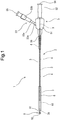
- a vascular occlusion balloon catheter (hereinafter referred to as balloon catheter) 2 of the present invention has a vascular occlusion balloon (hereinafter referred to as balloon) 10 elastically deformable and a shaft part having a main lumen 21 and a balloon expanding lumen 22.
- the vascular occlusion balloon catheter 2 has an air discharge passage 7.
- the air discharge passage 7 has a distal end (distal end opening 71) located at a position distal from the balloon 10 of the balloon catheter 2 and a proximal end communicates with an inner portion of the balloon 10.
- the distal end opening 71 of the air discharge passage 7 is positioned inside a portion disposed proximally from the distal end of the balloon catheter 2.
- the air discharge passage 7 communicates with the main lumen 21 at its distal end opening 71.
- the area of a cross section of the air discharge passage 7 orthogonal to an axial direction of the balloon catheter 2 is set to 200 ⁇ m 2 to 450 ⁇ m 2 .
- the length of the air discharge passage 7 is set to 1.0 to 3.0mm.
- the area of the cross section of the air discharge passage orthogonal to the axial direction of the balloon catheter is set to 200 ⁇ m 2 to 450 ⁇ m 2 .
- the length of the air discharge passage is set to 1.0 to 3.0mm.
- the air discharge passage having the above-described form allows the priming operation of replacing the air inside the balloon with the liquid to be reliably and satisfactorily performed and the liquid injected into the balloon to flow out in a small amount after the priming operation finishes.
- the distal end opening of the air discharge passage is positioned inside the portion disposed proximally from the distal end of the balloon catheter.
- the liquid inside the balloon flows out in a small mount because a medical liquid such as an imaging agent, a medical agent, and the like injected into the main lumen when the balloon catheter is used is obstructive to the flow-out of the liquid from the balloon. Therefore, the balloon is capable of keeping the blood vessel-occluded state for a predetermined period of time.
- a medical liquid such as an imaging agent, a medical agent, and the like injected into the main lumen when the balloon catheter is used is obstructive to the flow-out of the liquid from the balloon. Therefore, the balloon is capable of keeping the blood vessel-occluded state for a predetermined period of time.
- balloon catheter assembly vascular occlusion balloon catheter assembly
- a balloon catheter assembly 1 of this embodiment has the balloon catheter 2, a sleeve 8 covering the balloon 10 and restraining the balloon 10 from expanding, and a mandrel 9 entering the balloon catheter 2 from the distal end opening thereof, passing a position of the distal end opening 71 of the air discharge passage 7, and entering into the main lumen 21.
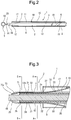
- the balloon catheter 2 has the shaft part and the balloon 10.
- the shaft part has an inner tube 3, an outer tube 4, and a hub 5.
- the balloon catheter 2 of this embodiment has the inner tube 3 having the main lumen 21, the outer tube 4 coaxial with the inner tube 3, having its distal end at a position rearward at a predetermined length from a distal end of the inner tube 3, and forming the balloon expanding lumen 22 between an outer surface of the inner tube 3 and the outer tube 4, and the expandable balloon 10 which has a distal side tubular part 12 fixed to the inner tube 3 and a proximal side tubular part 13 fixed to the outer tube 4, the inside of which communicates with the balloon expanding lumen 22.
- the inner tube 3 has an inner layer 32, an outer layer 33, a rigidity imparting body 35, and an imaging marker 34.
- the rigidity imparting body 35 is wound around the inner layer 32 and covered with the outer layer 33.
- the rigidity imparting body 35 is positioned inside a wall of the inner tube 3 and at a lower portion of the outer layer 33. Resin forming the outer layer 33 is present between filamentous forming the rigidity imparting body 35 embedded in the lower portion of the outer layer 33.
- the inner tube 3 is a tubular body open at its distal end and having the main lumen 21.
- the main lumen 21 is used to insert a guide wire thereinto and inject a liquid medicine thereinto.
- the main lumen 21 of the inner tube 3 communicates with a first open portion 54 formed on the branch hub 5.
- the inner tube 3 is inserted into the outer tube 4 with a distal end portion of the inner tube projecting beyond the outer tube 4.
- the second lumen (balloon expanding lumen) 22 is formed between an outer surface of the inner tube 3 and an inner surface of the outer tube 4 and has a sufficiently large volume.
- a ring-shaped imaging marker 34 is fixed to a small-diameter distal end portion 37 of the inner tube 3. It is preferable to form the imaging marker of a radiopaque material (for example, gold, platinum, tungsten or alloys of these metals or a silver-palladium alloy, a platinum-iridium alloy, and the like). Thereby it is possible to check the distal end portion of the balloon catheter 2 under X-ray fluoroscopy.
- a radiopaque material for example, gold, platinum, tungsten or alloys of these metals or a silver-palladium alloy, a platinum-iridium alloy, and the like.
- the balloon 10 to be used in this embodiment is elastically deformable.
- the balloon 10 has a bulged part 11 formed by plastic deformation, a distal side tubular part 12 which is formed at a distal side of the bulged part 11 and smaller than the bulged part 11 in its diameter and thicker than the bulged part 11, and a proximal side tubular part 13 which is formed at a proximal side of the bulged part 11 and smaller than the bulged part 11 in its diameter and thicker than the bulged part 11.
- the bulged part 11 can be extended owing to elastic deformation caused by an internal pressure applied thereto and is shaped into a diameter-decreased form having wrinkles extending axially.
- the balloon 10 is expandable and clings around the outer periphery of the inner tube 3.
- the bulged part 11 of the balloon 10 is expanded by a liquid injected thereinto and is capable of closely contacting an inner wall of a blood vessel. More specifically, the bulged part 11 is elastically restored to an originally shaped form from a configured diameter-decreased form by the liquid injected thereinto and thereafter extendable (expandable). Thereby the bulged part 11 securely closely contacts the inner wall of the blood vessel without damaging the inner wall thereof.
- the bulged part 11 is formed by stretching a material therefor at temperatures not less than its glass transition point and less than its softening point. The bulged part 11 expands without resistance until its plastic deformation shaped form (until original shaped form).
- the bulged part 11 is elastically expanded (extended) according to the degree of a pressure of the balloon expanding liquid injected thereinto. Thereafter, with a decrease in the degree of the pressure of the liquid injected thereinto, the bulged part 11 is elastically restored to a form before the bulged part is expanded.
- the bulged part 11 is thinner than that of the distal side tubular part 12 and that of the proximal side tubular part 13.
- the distal side tubular part 12 and the proximal side tubular part 13 are not substantially stretched in the radial direction thereof.
- An end portion 17 of the distal side tubular part 12 of the bulged part 11 and an end portion 16 of the proximal side tubular part 13 of the bulged part 11 are formed as thickness change portions which become gradually thinner toward the bulged part 11.
- the distal side tubular part 12 is a short tubular portion extending in almost an equal outer diameter and having a larger thickness than the bulged part 11.
- the proximal side tubular part 13 extends in almost an equal outer diameter and is longer than the distal side tubular part 12 in the axial direction thereof.
- the proximal side tubular part 13 is thicker than the bulged part 11.
- the distal side tubular part 12 has a smaller outer diameter than the proximal side tubular part 13 and is fixed to the distal end portion of the inner tube 3. It is preferable to fix the distal side tubular part 12 to the inner tube 3 by means of heat sealing.
- the proximal side tubular part 13 is not substantially expanded by the liquid injected into the balloon 10.
- the proximal side tubular part 13 forms a part of the balloon expanding lumen 22 between an inner surface thereof and an inner surface of the inner tube 3.
- elastic thermoplastic synthetic resins are used as materials to be used to form the balloon 10.
- synthetic resin such as urethane-based elastomer (for example, polyurethane elastomer), olefin-based elastomer (for example, polyethylene elastomer, polypropylene elastomer), polyester (for example, polyethylene terephthalate), soft polyvinyl chloride, amide-based elastomer (for example, polyamide elastomer), fluororesin elastomer and ethylene-vinyl acetate copolymer are favorable.
- urethane-based elastomer for example, polyurethane elastomer
- olefin-based elastomer for example, polyethylene elastomer, polypropylene elastomer
- polyester for example, polyethylene terephthalate
- soft polyvinyl chloride for example, polyamide-based elastomer (for example, polyamide elasto
- thermoplastic polyurethane elastomer for example, aromatic thermoplastic polyurethane elastomer, and aliphatic thermoplastic polyurethane elastomer
- thermoplastic polyurethane elastomer examples include aromatic and aliphatic thermoplastic elastomer polyurethanes.
- materials having a glass transition point not more than 0 degrees C are favorable and those having the glass transition point not more than -10 degrees C are more favorable.
- Materials having a softening point (Vicat softening point) not less than 70 degrees C are also favorable and those having the softening point in a range from 80 degrees C to 130 degrees C are more favorable.
- the balloon 10 has higher flexibility and pliability than the outer tube 4. It is preferable that the balloon 10 has higher flexibility and pliability than the inner tube 3 and the outer tube 4.
- the proximal side tubular part 13 is set longer than the distal side tubular part 12 in the axial direction thereof and extended toward the distal end portion of the balloon 10.
- the balloon 10 is allowed to have a long length and thus it is possible to form a long low profiling portion at a portion of the distal side of the balloon catheter.
- the proximal side tubular part 13 of the balloon 10 of this embodiment has a tubular portion extended at a predetermined length toward the distal end portion of the balloon 10.
- the proximal side tubular part 13 has an inclined proximal end surface 15 oblique to the central axis of the tubular portion.
- the proximal side tubular part 13 of the balloon 10 and a distal end portion of the outer tube 4 incline with respect to the central axis of the outer tube 4 and are fixed to a belt-shaped inclined annular fixing portion 6 formed airtightly.
- the outer diameter (outer diameter when the bulged part is restored to shaped form) of the bulged part 11 is set to favorably 0.90 to 2.10mm and more favorably 0.93 to 1.00mm.
- the outer diameter (expandable outer diameter) of the bulged part 11 is set to favorably 3.0 to 15.0mm and more favorably 4.0 to 8.0mm when the bulged part expands.
- the length of the bulged part 11 is set to favorably 3.5 to 14.5mm and more favorably 4.0 to 5.5mm.
- the radial stretch degree of the bulged part 11 is set to preferably 300 to 900%.
- the axial stretch degree of the bulged part 11 is set to preferably 200 to 350%.
- the outer diameter of the distal side tubular part 12 is set to favorably 0.70 to 1.85mm and more favorably 0.80 to 0.90mm.
- the axial length of the distal side tubular part 12 is set to favorably 2.0 to 7.0mm and more favorably 3.0 to 6.0mm.
- the outer diameter of the proximal side tubular part 13 is set to favorably 0.90 to 2.10mm and more favorably 0.93 to 1.00mm.
- the axial length of the proximal side tubular part 13 is set to favorably 10 to 60mm and more favorably 15 to 30mm.
- the bulged part 11 of the balloon 10 is thinner than the distal side tubular part 12 and the proximal side tubular part 13. It is favorable to set the thickness of the bulged part 11 smaller than that of the proximal side tubular part 13 and that of the distal side tubular part 12 by 0.03 to 0.18mm and more favorable to set the thickness thereof smaller than that of the proximal side tubular part and that the distal side tubular part by 0.04 to 0.11mm. It is favorable to set the thickness of the proximal side tubular part 13 and that of the distal side tubular part 12 to 0.07 to 0.20mm and more favorable to set the thickness thereof to 0.08 to 0.15mm.
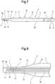
- the balloon 10 is fixed to the shaft part with the balloon 10 being axially stretched. Therefore, as shown in Figs. 2 and 7 , the balloon 10 is a little stretched axially. Thus, there is a further decrease in the diameter of the bulged part 11 shaped into a diameter-decreased form.
- the balloon catheter 2 has the air discharge passage 7 whose distal end opening 71 is positioned distally from the balloon 10 and whose proximal end 72 communicates with the inside of the distal end portion of the balloon 10.
- the distal end opening 71 is positioned inside a portion disposed proximally from the distal end of the balloon catheter 2.
- the air discharge passage 7 communicates with the main lumen 21 at the distal end opening 71.
- the distal end opening 71 of the air discharge passage 7 is positioned inside the portion disposed proximally from the distal end of the balloon catheter 2.
- the distal end opening 71 is not exposed to the outside.
- the distal end opening 71 of the air discharge passage 7 is positioned at the distal end of the inner tube 3.
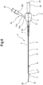
- the balloon catheter 2 of this embodiment has a distal end portion 20 as shown in Fig. 3 .
- the distal end portion 20 of the balloon catheter of this embodiment decreases toward its distal end in its outer and inner diameters.
- An inner surface of the distal end portion of the balloon catheter 2 is formed as an annular bulged portion bulged toward a center portion of the main lumen 21. Therefore, the distal end portion 20 has a thickness to some extent as whole and thus sufficiently high configuration retainability.
- the distal end portion 20 is thin in the vicinity of the distal end opening 71 of the air discharge passage 7. Therefore, the distal end portion 20 displays a high degree of flexibility and is thus obstructive to the discharge of air from the distal end opening 71. As shown in Fig.
- an inner surface of the distal end portion 20 is positioned forward from the distal end opening 71 of the air discharge passage 7. Therefore, air and the balloon expanding liquid which have flowed out from the distal end opening 71 of the air discharge passage 7 are brought into contact with the inner surface of the distal end portion 20.
- the inner surface of the distal end portion 20 is proximate to the distal end opening 71 of the air discharge passage 7.
- the inner surface of the distal end portion 20 constitutes an obstacle to the flow-out of the air and the balloon expanding liquid.
- an air discharge guide groove 73 which is continuous with the distal end opening 71 of the air discharge passage 7 and extended to the distal end of the balloon catheter 2 is formed on the inner surface of the distal end portion 20.
- a distal end 73a of the air discharge guide groove 73 is positioned at the distal end of the balloon catheter 2.
- the air discharge guide groove 73 allows air to be preferably discharged and prevents the air from being stored inside the distal end portion of the balloon catheter 2 when the inner surface of the distal end portion 20 contacts an outer surface of the shaft part 91 of the mandrel 9. As shown in Fig.
- a distal end 20 of a distal side tubular portion 12a of the balloon 10 is projected from the distal end of the inner tube 3.
- the distal end portion 20 of the balloon catheter 2 is formed.
- the air discharge passage 7 has the area of 200 ⁇ m 2 to 450 ⁇ m 2 in the cross section thereof orthogonal to the axial direction of the balloon catheter 2 and has a length of 1.0 to 3.0mm.
- the area of the balloon catheter 2 in the cross section thereof orthogonal to the axial direction thereof is 250 ⁇ m 2 to 350 ⁇ m 2 and the length of the air discharge passage to 1.0 to 2.0mm.
- the air discharge passage 7 has a form whose configuration in a cross section orthogonal to the axial direction of the balloon catheter 2 is elongated in a circumferential direction of the balloon catheter 2.
- a length W of the air discharge passage 7 in the circumferential direction of the balloon catheter 2 is set to 1 to 1.5 times as large as a width H of the air discharge passage. It is more preferable to set the length W two to four times as large as the width H.
- the air discharge passage 7 may have an elliptic sectional configuration having a major axis in the circumferential direction of the balloon catheter 2 and a minor axis in the radial direction thereof.
- the sectional configuration of the air discharge passage 7 may be a perfect circle, may be extended in a predetermined length and in the same height in the circumferential direction of the balloon catheter 2 or may be bulged at both sides of the air discharge passage 7 like a gourd.
- the air discharge passage 7 may be so constructed as to allow the discharge of air and make it difficult for the balloon expanding liquid to enter thereinto.
- the entire air discharge passage 7 has the form in which the configuration of the air discharge passage 7 in the cross section thereof orthogonal to the axial direction of the balloon catheter 2 is elongated in the circumferential direction of the balloon catheter 2, as described above.
- the cross section of the air discharge passage 7 in the central axis direction of the balloon catheter 2 it is possible to decrease the width (length of minor axis) of an air discharge port and thereby reduce an increase of the outer diameter of the balloon catheter as much as possible. Because the air discharge port 7 is elongated in the circumferential direction of the balloon catheter 2, the air discharge port displays a sufficiently high discharge function.
- the air discharge passage 7 is formed between the inner surface of the balloon 10 and the inner tube 3. More specifically, the air discharge passage 7 is positioned between the outer surface of the imaging marker 34 and a distal end thin portion 12a of the balloon 10 at the distal end portion thereof and positioned between the outer surface of the inner tube 3 and the distal end portion of the balloon 10 at the proximal end portion thereof.
- the shaft part has the ring-shaped imaging marker 34 provided at the distal end portion of the inner tube 3 and a marker covering portion (distal side thin portion 12a) covering the ring-shaped imaging marker 34.
- a part of the air discharge passage 7 is extended between the ring-shaped imaging marker and the marker covering portion (distal side thin portion 12a).
- the bulged part 11, of the balloon 10 which is shaped by plastic deformation and can be expanded by elastic deformation.
- the bulged part 11 can be extended (expanded) by the elastic deformation by applying an internal pressure to the balloon 10 and is restored to a configuration before it is elastically deformed by releasing the applied internal pressure.
- the distal side tubular part 12 and the proximal side tubular part 13 are smaller than the bulged part 11 in the diameters thereof and thicker than the bulged part and cannot be substantially expanded.
- the bulged part 11 of the balloon 10 is elastically restored to the originally shaped form by the balloon-expanding liquid injected into the balloon and thereafter extendable (expandable). Thereby the bulged part 11 securely closely contacts the inner wall of the blood vessel without damaging the inner wall thereof.
- the bulged part 11 can be formed by stretching the material used therefor at temperatures not less than its glass transition point and less than its softening point.
- the bulged part 11 expands without resistance until its plastic deformation shaped form (until originally shaped form). Thereafter, the bulged part 11 is elastically expanded (extended) according to the degree of the pressure of the balloon expanding liquid injected thereinto. Thereafter, with a decrease in the degree of the pressure of the liquid injected thereinto, the bulged part 11 is elastically restored to the form before the bulged part is expanded.
- An air discharge liquid is capable of entering when the air discharge liquid is injected into the balloon 10 having the above-described form to such an extent that the bulged part 11 expands beyond the form shaped by the plastic deformation.
- the outer tube 4 is a tubular body into which the inner tube 3 is inserted. A distal end of the outer tube 4 is positioned at a portion rearward or proximal from the distal end of the inner tube 3 at a predetermined length.
- the distal end of the balloon expanding lumen 22 communicates with the distal end portion of the balloon 10. As described later, the proximal end of the balloon expanding lumen 22 communicates with a second open portion 55 of an injection port 53, provided on a branch hub 5, into which the balloon expanding fluid (for example, balloon expanding liquid, specifically angiographic agent) is injected.
- the balloon expanding fluid for example, balloon expanding liquid, specifically angiographic agent
- materials to be used to form the outer tube 4 and the inner tube 3 materials having hardness and flexibility to some extent are preferable.
- polyolefin such as polyethylene and polypropylene; polyamide; polyester such as an polyethylene terephthalate; fluorine-based polymer such as PTFE and ETFE; PEEK (polyether ether ketone); polyimide; synthetic resin elastomer such as olefinic elastomer (for example, polyethylene elastomer and polypropylene elastomer), polyamide elastomer, styrenic elastomer (for example, a styrene-butadiene-styrene copolymer, a styrene-isoprene-styrene copolymer, a styrene-ethylene butylene-styrene copolymer); polyurethane, urethane-based elastomer, and fluorine
- the outer tube 4 and the inner tube 3 may be provided with a rigidity imparting body 35.
- a material for the rigidity imparting body 35 a braid formed of a metal wire or a synthetic resin wire is preferable.
- a braid formed of a metal wire or a synthetic resin wire is preferable.
- an inclined annular fixing portion (in other words, inclined annular joining portion) for joining the proximal side tubular part 13 of the balloon 10 of the balloon catheter of this embodiment and the distal end portion of the outer tube 4 with each other.
- the outer tube 4 has an inclined distal end surface 41 oblique to the central axis of the outer tube 4 disposed at the distal end portion thereof.
- the balloon 10 has an inclined proximal end surface 15 oblique to the central axis of the proximal side tubular part 13 disposed at the proximal side tubular part 13 thereof.
- the distal end portion of the outer tube 4 and the proximal side tubular part 13 of the balloon 10 overlap each other at a portion in the axial direction of the balloon catheter.
- the balloon catheter 2 has a belt-shaped inclined annular fixing portion 6 provided at a portion where the distal end portion of the outer tube 4 and the proximal side tubular part 13 of the balloon 10 overlap each other.
- the inclined annular fixing portion 6 inclines with respect to the central axis of the outer tube 4 and is formed airtightly.
- the inclined annular fixing portion 6 allows a gradual change of the property of the fixing portion for fixing the proximal end portion of the balloon of the balloon catheter and the distal end portion of the outer tube 4 to each other. Thus, it does not occur that a portion where the property of the outer tube 4 changes rapidly is formed in the vicinity of the distal end of the outer tube 4 and in the vicinity of the proximal end of the balloon 10.
- the outer tube 4 and the balloon 10 hardly kink. Thus, it is possible to favorably perform an operation of inserting the balloon catheter into the blood vessel.
- the branch hub 5 has an inner tube hub 52 which has a first open portion 54 communicating with the main lumen 21 and is fixed to the proximal end portion of the inner tube 3, an outer tube hub 51 which has a second open portion 55 communicating with the balloon expanding lumen 22 and provided at an end of an injection port 53 and which is fixed to the proximal end portion of the outer tube 4.
- the outer tube hub 51 and the inner tube hub 52 are fixed to each other.
- the distal end of the inner tube 3 is inserted into a proximal end of the outer tube hub 51 mounted on the proximal portion of the outer tube 4.
- the branch hub 5 is provided with a bending prevention tube 56 covering the proximal portion of the outer tube 4 and a distal end portion of the branch hub 5.
- the injection port 53 is formed of a branch port 53a extended from a side wall of the outer tube hub 51, an injection port hub 53b, and a connection tube 53c connecting the branch port 53a and the injection port hub 53b to each other.
- thermoplastic resin such as polycarbonate, polyamide, polysulfone, polyarylate, and methacrylate-butylene-styrene copolymer.
- connection tube a synthetic resin tube flexible or soft is used.
- the construction of the balloon catheter is not limited to the above-described ones, but the balloon catheter may have a guide wire insertion opening communicating with a guide wire lumen at an intermediate portion (rearward from the inclined annular fixing portion 6) thereof.
- the balloon catheter assembly 1 of the present invention has the sleeve 8 covering the balloon 10 of the balloon catheter 2 and restraining the balloon 10 from expanding.
- the sleeve 8 is removable from the distal end of the balloon catheter 2.
- a tubular member is used as the sleeve 8.
- a transparent tubular member allowing the balloon to be visually recognizable is suitably used.
- the sleeve 8 may be so dimensioned and configured as to cover the entire balloon 10. As shown in Fig. 3 , it is preferable that the sleeve 8 can be mounted on the balloon when the balloon is not in an expanded state but in a state in which the balloon is extended a little in its axial direction and is positioned on the balloon so long as the sleeve is not operated. It is also preferable that the sleeve 8 is flexible to some extent.
- the balloon catheter assembly 1 of the present invention has the mandrel 9 which enters the balloon catheter 2 from the distal end opening thereof and the distal end of which reaches into the main lumen 21 after the mandrel 9 passes the distal end opening 71 of the air discharge passage 7.
- the mandrel 9 can be removed from the balloon catheter 2 from its distal end.
- the mandrel 9 of this embodiment has a shaft part 91 and a gripping part 92 fixed to the proximal end of the shaft part 91.
- a linear body rigid to some extent is preferable.
- a metal wire can be preferably used.
- the shaft part 91 used in this embodiment has an outer diameter a little smaller than the inner diameter of the distal end portion 20 of the balloon catheter 2 and the inner diameter of the inner tube (inner diameter of the main lumen).
- the shaft part 91 used in this embodiment has a length so dimensioned that its distal end is capable of reaching into at least the inner tube (into the main lumen).
- the shaft part 91 To prevent the shaft part 91 from kinking at the distal end of the sleeve 8 during a priming operation, it is preferable for the shaft part 91 to have a length so dimensioned that its distal end is disposed proximally from the distal end of the sleeve 8 and more preferable for the shaft part 91 to have a length so dimensioned that its distal end is disposed proximally from the proximal end of the bulged part 11.
- the shaft part 91 may be so formed that its distal end has a reduced diameter. Thereby the shaft part 91 can be easily inserted into the distal end opening of the balloon catheter 2.
- the priming operation of replacing air inside the balloon expanding lumen 22 with a liquid is performed with the sleeve 8 and the mandrel 9 being mounted on the balloon catheter 2.
- a syringe in which a priming liquid has been filled is mounted on the open portion 55 of the injection port 53 provided on the outer tube hub 51 of the branch hub 5.
- the distal side of the balloon catheter assembly 1 (more specifically, part in the range from the distal end of the assembly to a position rearward from the proximal end of the sleeve 8) is immersed in the liquid.
- the syringe is operated to inject the priming liquid to the balloon expanding lumen 22.
- air inside the balloon expanding lumen 22 and the balloon 10 is pressed by the priming liquid injected into the balloon expanding lumen 22 and consequently transferred inside the balloon.
- the air inside the balloon is flowed out from the distal end opening of the air discharge passage 7 by continuous injection of the priming liquid into the balloon expanding lumen 22.
- the air flowed out from the distal end opening of the air discharge passage 7 passes through the air discharge guide groove 73 or the gap between the shaft 91 of the mandrel 9 and the distal end portion 20 of the balloon catheter and is discharged from the distal end of the balloon catheter 2.
- the balloon 10 is covered with the sleeve 8 and thus the balloon is restrained from expanding. Therefore, a small amount of the priming liquid flows into the balloon 10. Further, because the mandrel 9 is mounted on the balloon catheter assembly, the distal end portion of the balloon catheter 2 is restrained from deforming. Thereby the priming operation can be easily accomplished. Furthermore, the mandrel 9 mounted on the balloon catheter assembly restrains the air which has flowed out from the distal end opening 71 of the air discharge passage 7 open inside the balloon catheter 2 from flowing into the main lumen 21. Thereby the air can be satisfactorily transferred to the distal end of the balloon catheter 2.
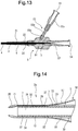
- the balloon catheter may have the form of a distal end portion of a balloon catheter 2a shown in Fig. 14 .
- the inner tube body 30 has the small-diameter distal end portion 37 to which the ring-shaped imaging marker 34 is fixed.
- the distal end opening 71 of the air discharge passage 7 is positioned at the distal end of the imaging marker 34 and the distal end of the inner tube 3.
- the outer diameter of the ring-shaped imaging marker 34 is set equally to that of the inner tube body 30.
- the length of the small-diameter distal end portion 37 of the inner tube body 30 is set to favorably 1.0 to 4.0mm and more favorably 1.0 to 3.0mm.
- the outer diameter of the small-diameter distal end portion 37 is set smaller favorably by 0.01 to 0.3mm and more favorably by 0.02 to 0.2mm than that of the inner tube except for the small diameter portion thereof.
- the small-diameter portion 37 is formed of a miss portion of the outer surface layer 33 of the inner tube body 30. More specifically, the small-diameter portion 37 is formed by partially removing the outer surface layer of the outer layer 33. The outer surface layer is partially removed by scraping the outer surface layer or dissolving it with a solvent capable of dissolving it.
- the rigidity imparting body 35 is formed extendedly to the distal end portion of the small-diameter portion 37 and not provided at the portion where the imaging marker 34 is disposed.
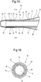
- the balloon catheter may have the form of a distal end portion of a balloon catheter 2b shown in Figs. 15 and 16 .
- the balloon catheter 2b of this embodiment has a plurality of air discharge passages 7a.
- the distal end opening 71 of each air discharge passage 7a is located at a position distal from the balloon of the balloon catheter and inside the balloon catheter.
- the other end 72 of each air discharge passage 7a communicates with the distal end portion of the inner space of the balloon 10.
- the air discharge passage 7a of this embodiment has the distal end opening 71 which is open inside the balloon catheter 2b and at the distal end of the inner tube 3 and is extended toward the proximal end of the balloon catheter 2b in its axial direction.
- the other end 72 of the air discharge passage 7a communicates with the distal end of the space inside the balloon 10
- the distal end portion 20 is formed at the distal end of the inner tube 3.
- the outer surface of the imaging marker 34 is covered with the distal side thin portion 12a of the balloon 10. Thus, the outer surface of the imaging marker 34 is not exposed to the outside.
- the air discharge passage 7a is formed between the inner surface of the balloon 10 and the inner tube 3. More specifically, the distal end portion of the air discharge passage 7a is positioned between the outer surface of the imaging marker 34 and the distal side thin portion 12a of the balloon 10. The proximal end portion of the air discharge passage 7a is positioned between the outer surface of the inner tube 3 and the distal end portion of the balloon 10.
- the shaft part has the ring-shaped imaging marker 34 provided at the distal end portion of the inner tube 3 and the marker covering portion (distal side thin portion 12a) covering the ring-shaped imaging marker 34.
- a part of the air discharge passage 7a is extended between the ring-shaped imaging marker 34 and the marker covering portion (distal side thin portion 12a).
- the air discharge passage 7a of this embodiment has one end (distal end opening) 71 which is open at the distal end surface of the balloon catheter 2b and is extended toward the proximal end of the balloon catheter 2b in its axial direction.
- the other end 72 of the air discharge passage 7a communicates with the distal end of the inner space disposed inside the balloon 10.
- the balloon catheter 2b has a plurality of the air discharge passages 7a.
- the air discharge passages 7a are extended almost parallel with the central axis of the inner tube 3.
- the total of the areas of the cross sections of the air discharge passages 7 orthogonal to the axial direction of the balloon catheter 2b is set to 200 ⁇ m 2 to 450 ⁇ m 2 . It is favorable to set the total of the areas of the cross sections of the air discharge passages 7 orthogonal to the axial direction of the balloon catheter 2b to 250 ⁇ m 2 to 350 ⁇ m 2 .
- each of the air discharge passages 7a orthogonal to the axial direction of the balloon catheter 2b is favorable to set the length of each of the air discharge passages 7a to 1.0 to 2.0mm.
- the sectional configuration of the air discharge passage 7a may be elongated in the axial direction of the balloon catheter or elongated to some extent in the axial direction of the balloon catheter.
- the vascular occlusion balloon catheter of the present invention has the following form:.
Landscapes
- Health & Medical Sciences (AREA)
- Life Sciences & Earth Sciences (AREA)
- Heart & Thoracic Surgery (AREA)
- Animal Behavior & Ethology (AREA)
- Veterinary Medicine (AREA)
- Public Health (AREA)
- Engineering & Computer Science (AREA)
- Biomedical Technology (AREA)
- General Health & Medical Sciences (AREA)
- Surgery (AREA)
- Vascular Medicine (AREA)
- Anesthesiology (AREA)
- Hematology (AREA)
- Pulmonology (AREA)
- Biophysics (AREA)
- Molecular Biology (AREA)
- Medical Informatics (AREA)
- Nuclear Medicine, Radiotherapy & Molecular Imaging (AREA)
- Reproductive Health (AREA)
- Child & Adolescent Psychology (AREA)
- Emergency Medicine (AREA)
- Media Introduction/Drainage Providing Device (AREA)
Applications Claiming Priority (1)
| Application Number | Priority Date | Filing Date | Title |
|---|---|---|---|
| JP2016062215A JP6682726B2 (ja) | 2016-03-25 | 2016-03-25 | 血管閉塞用バルーンカテーテル |
Publications (2)
| Publication Number | Publication Date |
|---|---|
| EP3222317A1 EP3222317A1 (en) | 2017-09-27 |
| EP3222317B1 true EP3222317B1 (en) | 2018-11-21 |
Family
ID=58410214
Family Applications (1)
| Application Number | Title | Priority Date | Filing Date |
|---|---|---|---|
| EP17162665.8A Active EP3222317B1 (en) | 2016-03-25 | 2017-03-23 | Vascular occlusion balloon catheter |
Country Status (4)
| Country | Link |
|---|---|
| US (1) | US10905860B2 (enExample) |
| EP (1) | EP3222317B1 (enExample) |
| JP (1) | JP6682726B2 (enExample) |
| ES (1) | ES2711224T3 (enExample) |
Cited By (2)
| Publication number | Priority date | Publication date | Assignee | Title |
|---|---|---|---|---|
| EP4054693A1 (en) * | 2019-11-07 | 2022-09-14 | Stryker Corporation | Balloon catheter assembly for insertion and positioning therapeutic devices within a vascular system |
| US12310843B2 (en) | 2020-08-24 | 2025-05-27 | Edwards Lifesciences Corporation | Balloon cover for a delivery apparatus for an expandable prosthetic heart valve |
Families Citing this family (4)
| Publication number | Priority date | Publication date | Assignee | Title |
|---|---|---|---|---|
| US11096781B2 (en) | 2016-08-01 | 2021-08-24 | Edwards Lifesciences Corporation | Prosthetic heart valve |
| US11957855B2 (en) * | 2019-05-09 | 2024-04-16 | Neuravi Limited | Balloon guide catheter with positive venting of residual air |
| JP2023515212A (ja) * | 2020-02-25 | 2023-04-12 | バイオフロー インク | 隔離ドレナージカテーテル |
| CN115634360B (zh) * | 2022-10-24 | 2025-04-18 | 上海悦灵医疗科技有限公司 | 头端排气的三叉神经压迫球囊装置 |
Family Cites Families (15)
| Publication number | Priority date | Publication date | Assignee | Title |
|---|---|---|---|---|
| CA1257170A (en) * | 1984-10-31 | 1989-07-11 | Suha V. Ari | Rapidly inflatable balloon catheter and method |
| US5449343A (en) | 1985-07-30 | 1995-09-12 | Advanced Cardiovascular Systems, Inc. | Steerable dilatation catheter |
| US4638805A (en) | 1985-07-30 | 1987-01-27 | Advanced Cardiovascular Systems, Inc. | Self-venting balloon dilatation catheter and method |
| US4921483A (en) * | 1985-12-19 | 1990-05-01 | Leocor, Inc. | Angioplasty catheter |
| US4938220A (en) * | 1986-08-01 | 1990-07-03 | Advanced Cardiovascular Systems, Inc. | Catheter with split tip marker and method of manufacture |
| US4821722A (en) | 1987-01-06 | 1989-04-18 | Advanced Cardiovascular Systems, Inc. | Self-venting balloon dilatation catheter and method |
| US5256143A (en) * | 1987-01-06 | 1993-10-26 | Advanced Cardiovascular Systems, Inc. | Self-venting balloon dilatation catheter |
| US4793350A (en) * | 1987-01-06 | 1988-12-27 | Advanced Cardiovascular Systems, Inc. | Liquid filled low profile dilatation catheter |
| US5049130A (en) * | 1988-12-23 | 1991-09-17 | Cardiovascular Imaging Systems, Inc. | System and method for pressure filling of catheters |
| US5135486A (en) * | 1990-08-31 | 1992-08-04 | Endosonics Corporation | Self-venting balloon dilitation catheter |
| JP4264886B2 (ja) | 2003-10-01 | 2009-05-20 | テルモ・クリニカルサプライ株式会社 | バルーンカテーテル |
| US8419685B2 (en) * | 2006-01-30 | 2013-04-16 | The Regents Of The University Of California | Endovascular catheter air block |
| JP5334781B2 (ja) * | 2009-09-29 | 2013-11-06 | 株式会社カネカ | バルーンカテーテル |
| JP6205550B2 (ja) * | 2013-02-07 | 2017-10-04 | テルモ・クリニカルサプライ株式会社 | バルーンカテーテル |
| US10220161B2 (en) * | 2014-02-14 | 2019-03-05 | Ailnh, Llc | Gas removal systems and methods |
-
2016
- 2016-03-25 JP JP2016062215A patent/JP6682726B2/ja active Active
-
2017
- 2017-03-23 ES ES17162665T patent/ES2711224T3/es active Active
- 2017-03-23 EP EP17162665.8A patent/EP3222317B1/en active Active
- 2017-03-24 US US15/468,592 patent/US10905860B2/en active Active
Non-Patent Citations (1)
| Title |
|---|
| None * |
Cited By (3)
| Publication number | Priority date | Publication date | Assignee | Title |
|---|---|---|---|---|
| EP4054693A1 (en) * | 2019-11-07 | 2022-09-14 | Stryker Corporation | Balloon catheter assembly for insertion and positioning therapeutic devices within a vascular system |
| US12226601B2 (en) | 2019-11-07 | 2025-02-18 | Stryker Corporation | Balloon catheter assembly for insertion and positioning therapeutic devices within a vascular system |
| US12310843B2 (en) | 2020-08-24 | 2025-05-27 | Edwards Lifesciences Corporation | Balloon cover for a delivery apparatus for an expandable prosthetic heart valve |
Also Published As
| Publication number | Publication date |
|---|---|
| EP3222317A1 (en) | 2017-09-27 |
| JP6682726B2 (ja) | 2020-04-15 |
| US10905860B2 (en) | 2021-02-02 |
| ES2711224T3 (es) | 2019-04-30 |
| JP2017170005A (ja) | 2017-09-28 |
| US20170274188A1 (en) | 2017-09-28 |
Similar Documents
| Publication | Publication Date | Title |
|---|---|---|
| EP3222317B1 (en) | Vascular occlusion balloon catheter | |
| CN104981266B (zh) | 球囊导管 | |
| JP6875374B2 (ja) | 医療用長尺体 | |
| CN114288528B (zh) | 一种球囊微导管及其制备方法 | |
| JP2017170005A5 (enExample) | ||
| WO2013146306A1 (ja) | 血管閉塞用バルーンカテーテル | |
| CN113546287A (zh) | 一种球囊扩张导管 | |
| US5403339A (en) | Blood vessel dilator | |
| JP2002355313A (ja) | カテーテルチューブおよびバルーンカテーテル | |
| JP6201123B2 (ja) | バルーンカテーテル | |
| CN112827057B (zh) | 球囊导管 | |
| JP2015181673A (ja) | 塞栓治療デバイス | |
| US20230129088A1 (en) | Catheter | |
| JP6205549B2 (ja) | バルーンカテーテル | |
| US20250010031A1 (en) | Catheter | |
| JP2002360698A (ja) | カテーテル | |
| JP2025170867A (ja) | 医療デバイス | |
| JP2025051095A (ja) | カテーテル | |
| JP2025051096A (ja) | カテーテル | |
| WO2017159039A1 (ja) | ステント | |
| JP2024141499A (ja) | コアワイヤ、及びバルーンカテーテル | |
| CN120112232A (zh) | 十二指肠乳头部插入用冷冻消融导管及冷冻消融导管系统 | |
| WO2025069714A1 (ja) | カテーテル | |
| JP2019216944A (ja) | カテーテル | |
| WO2024202775A1 (ja) | バルーンカテーテル |
Legal Events
| Date | Code | Title | Description |
|---|---|---|---|
| PUAI | Public reference made under article 153(3) epc to a published international application that has entered the european phase |
Free format text: ORIGINAL CODE: 0009012 |
|
| STAA | Information on the status of an ep patent application or granted ep patent |
Free format text: STATUS: THE APPLICATION HAS BEEN PUBLISHED |
|
| AK | Designated contracting states |
Kind code of ref document: A1 Designated state(s): AL AT BE BG CH CY CZ DE DK EE ES FI FR GB GR HR HU IE IS IT LI LT LU LV MC MK MT NL NO PL PT RO RS SE SI SK SM TR |
|
| AX | Request for extension of the european patent |
Extension state: BA ME |
|
| STAA | Information on the status of an ep patent application or granted ep patent |
Free format text: STATUS: REQUEST FOR EXAMINATION WAS MADE |
|
| REG | Reference to a national code |
Ref country code: DE Ref legal event code: R079 Ref document number: 602017000953 Country of ref document: DE Free format text: PREVIOUS MAIN CLASS: A61M0025100000 Ipc: A61B0017120000 |
|
| 17P | Request for examination filed |
Effective date: 20180320 |
|
| RBV | Designated contracting states (corrected) |
Designated state(s): AL AT BE BG CH CY CZ DE DK EE ES FI FR GB GR HR HU IE IS IT LI LT LU LV MC MK MT NL NO PL PT RO RS SE SI SK SM TR |
|
| GRAP | Despatch of communication of intention to grant a patent |
Free format text: ORIGINAL CODE: EPIDOSNIGR1 |
|
| STAA | Information on the status of an ep patent application or granted ep patent |
Free format text: STATUS: GRANT OF PATENT IS INTENDED |
|
| RIC1 | Information provided on ipc code assigned before grant |
Ipc: A61B 17/12 20060101AFI20180424BHEP Ipc: A61M 25/01 20060101ALI20180424BHEP Ipc: A61M 25/10 20130101ALI20180424BHEP |
|
| INTG | Intention to grant announced |
Effective date: 20180529 |
|
| GRAS | Grant fee paid |
Free format text: ORIGINAL CODE: EPIDOSNIGR3 |
|
| GRAA | (expected) grant |
Free format text: ORIGINAL CODE: 0009210 |
|
| STAA | Information on the status of an ep patent application or granted ep patent |
Free format text: STATUS: THE PATENT HAS BEEN GRANTED |
|
| AK | Designated contracting states |
Kind code of ref document: B1 Designated state(s): AL AT BE BG CH CY CZ DE DK EE ES FI FR GB GR HR HU IE IS IT LI LT LU LV MC MK MT NL NO PL PT RO RS SE SI SK SM TR |
|
| REG | Reference to a national code |
Ref country code: CH Ref legal event code: EP |
|
| REG | Reference to a national code |
Ref country code: IE Ref legal event code: FG4D |
|
| REG | Reference to a national code |
Ref country code: AT Ref legal event code: REF Ref document number: 1066600 Country of ref document: AT Kind code of ref document: T Effective date: 20181215 |
|
| REG | Reference to a national code |
Ref country code: DE Ref legal event code: R096 Ref document number: 602017000953 Country of ref document: DE |
|
| REG | Reference to a national code |
Ref country code: NL Ref legal event code: MP Effective date: 20181121 |
|
| REG | Reference to a national code |
Ref country code: AT Ref legal event code: MK05 Ref document number: 1066600 Country of ref document: AT Kind code of ref document: T Effective date: 20181121 |
|
| PG25 | Lapsed in a contracting state [announced via postgrant information from national office to epo] |
Ref country code: HR Free format text: LAPSE BECAUSE OF FAILURE TO SUBMIT A TRANSLATION OF THE DESCRIPTION OR TO PAY THE FEE WITHIN THE PRESCRIBED TIME-LIMIT Effective date: 20181121 Ref country code: AT Free format text: LAPSE BECAUSE OF FAILURE TO SUBMIT A TRANSLATION OF THE DESCRIPTION OR TO PAY THE FEE WITHIN THE PRESCRIBED TIME-LIMIT Effective date: 20181121 Ref country code: LT Free format text: LAPSE BECAUSE OF FAILURE TO SUBMIT A TRANSLATION OF THE DESCRIPTION OR TO PAY THE FEE WITHIN THE PRESCRIBED TIME-LIMIT Effective date: 20181121 Ref country code: BG Free format text: LAPSE BECAUSE OF FAILURE TO SUBMIT A TRANSLATION OF THE DESCRIPTION OR TO PAY THE FEE WITHIN THE PRESCRIBED TIME-LIMIT Effective date: 20190221 Ref country code: FI Free format text: LAPSE BECAUSE OF FAILURE TO SUBMIT A TRANSLATION OF THE DESCRIPTION OR TO PAY THE FEE WITHIN THE PRESCRIBED TIME-LIMIT Effective date: 20181121 Ref country code: LV Free format text: LAPSE BECAUSE OF FAILURE TO SUBMIT A TRANSLATION OF THE DESCRIPTION OR TO PAY THE FEE WITHIN THE PRESCRIBED TIME-LIMIT Effective date: 20181121 Ref country code: IS Free format text: LAPSE BECAUSE OF FAILURE TO SUBMIT A TRANSLATION OF THE DESCRIPTION OR TO PAY THE FEE WITHIN THE PRESCRIBED TIME-LIMIT Effective date: 20190321 Ref country code: NO Free format text: LAPSE BECAUSE OF FAILURE TO SUBMIT A TRANSLATION OF THE DESCRIPTION OR TO PAY THE FEE WITHIN THE PRESCRIBED TIME-LIMIT Effective date: 20190221 |
|
| REG | Reference to a national code |
Ref country code: ES Ref legal event code: FG2A Ref document number: 2711224 Country of ref document: ES Kind code of ref document: T3 Effective date: 20190430 |
|
| PG25 | Lapsed in a contracting state [announced via postgrant information from national office to epo] |
Ref country code: RS Free format text: LAPSE BECAUSE OF FAILURE TO SUBMIT A TRANSLATION OF THE DESCRIPTION OR TO PAY THE FEE WITHIN THE PRESCRIBED TIME-LIMIT Effective date: 20181121 Ref country code: NL Free format text: LAPSE BECAUSE OF FAILURE TO SUBMIT A TRANSLATION OF THE DESCRIPTION OR TO PAY THE FEE WITHIN THE PRESCRIBED TIME-LIMIT Effective date: 20181121 Ref country code: GR Free format text: LAPSE BECAUSE OF FAILURE TO SUBMIT A TRANSLATION OF THE DESCRIPTION OR TO PAY THE FEE WITHIN THE PRESCRIBED TIME-LIMIT Effective date: 20190222 Ref country code: PT Free format text: LAPSE BECAUSE OF FAILURE TO SUBMIT A TRANSLATION OF THE DESCRIPTION OR TO PAY THE FEE WITHIN THE PRESCRIBED TIME-LIMIT Effective date: 20190321 Ref country code: AL Free format text: LAPSE BECAUSE OF FAILURE TO SUBMIT A TRANSLATION OF THE DESCRIPTION OR TO PAY THE FEE WITHIN THE PRESCRIBED TIME-LIMIT Effective date: 20181121 Ref country code: SE Free format text: LAPSE BECAUSE OF FAILURE TO SUBMIT A TRANSLATION OF THE DESCRIPTION OR TO PAY THE FEE WITHIN THE PRESCRIBED TIME-LIMIT Effective date: 20181121 |
|
| PG25 | Lapsed in a contracting state [announced via postgrant information from national office to epo] |
Ref country code: PL Free format text: LAPSE BECAUSE OF FAILURE TO SUBMIT A TRANSLATION OF THE DESCRIPTION OR TO PAY THE FEE WITHIN THE PRESCRIBED TIME-LIMIT Effective date: 20181121 Ref country code: DK Free format text: LAPSE BECAUSE OF FAILURE TO SUBMIT A TRANSLATION OF THE DESCRIPTION OR TO PAY THE FEE WITHIN THE PRESCRIBED TIME-LIMIT Effective date: 20181121 Ref country code: CZ Free format text: LAPSE BECAUSE OF FAILURE TO SUBMIT A TRANSLATION OF THE DESCRIPTION OR TO PAY THE FEE WITHIN THE PRESCRIBED TIME-LIMIT Effective date: 20181121 |
|
| REG | Reference to a national code |
Ref country code: DE Ref legal event code: R097 Ref document number: 602017000953 Country of ref document: DE |
|
| PG25 | Lapsed in a contracting state [announced via postgrant information from national office to epo] |
Ref country code: SK Free format text: LAPSE BECAUSE OF FAILURE TO SUBMIT A TRANSLATION OF THE DESCRIPTION OR TO PAY THE FEE WITHIN THE PRESCRIBED TIME-LIMIT Effective date: 20181121 Ref country code: EE Free format text: LAPSE BECAUSE OF FAILURE TO SUBMIT A TRANSLATION OF THE DESCRIPTION OR TO PAY THE FEE WITHIN THE PRESCRIBED TIME-LIMIT Effective date: 20181121 Ref country code: SM Free format text: LAPSE BECAUSE OF FAILURE TO SUBMIT A TRANSLATION OF THE DESCRIPTION OR TO PAY THE FEE WITHIN THE PRESCRIBED TIME-LIMIT Effective date: 20181121 Ref country code: RO Free format text: LAPSE BECAUSE OF FAILURE TO SUBMIT A TRANSLATION OF THE DESCRIPTION OR TO PAY THE FEE WITHIN THE PRESCRIBED TIME-LIMIT Effective date: 20181121 |
|
| PLBE | No opposition filed within time limit |
Free format text: ORIGINAL CODE: 0009261 |
|
| STAA | Information on the status of an ep patent application or granted ep patent |
Free format text: STATUS: NO OPPOSITION FILED WITHIN TIME LIMIT |
|
| 26N | No opposition filed |
Effective date: 20190822 |
|
| PG25 | Lapsed in a contracting state [announced via postgrant information from national office to epo] |
Ref country code: MC Free format text: LAPSE BECAUSE OF FAILURE TO SUBMIT A TRANSLATION OF THE DESCRIPTION OR TO PAY THE FEE WITHIN THE PRESCRIBED TIME-LIMIT Effective date: 20181121 Ref country code: SI Free format text: LAPSE BECAUSE OF FAILURE TO SUBMIT A TRANSLATION OF THE DESCRIPTION OR TO PAY THE FEE WITHIN THE PRESCRIBED TIME-LIMIT Effective date: 20181121 |
|
| PG25 | Lapsed in a contracting state [announced via postgrant information from national office to epo] |
Ref country code: LU Free format text: LAPSE BECAUSE OF NON-PAYMENT OF DUE FEES Effective date: 20190323 |
|
| REG | Reference to a national code |
Ref country code: BE Ref legal event code: MM Effective date: 20190331 |
|
| PG25 | Lapsed in a contracting state [announced via postgrant information from national office to epo] |
Ref country code: IE Free format text: LAPSE BECAUSE OF NON-PAYMENT OF DUE FEES Effective date: 20190323 |
|
| PG25 | Lapsed in a contracting state [announced via postgrant information from national office to epo] |
Ref country code: BE Free format text: LAPSE BECAUSE OF NON-PAYMENT OF DUE FEES Effective date: 20190331 |
|
| PG25 | Lapsed in a contracting state [announced via postgrant information from national office to epo] |
Ref country code: TR Free format text: LAPSE BECAUSE OF FAILURE TO SUBMIT A TRANSLATION OF THE DESCRIPTION OR TO PAY THE FEE WITHIN THE PRESCRIBED TIME-LIMIT Effective date: 20181121 |
|
| PG25 | Lapsed in a contracting state [announced via postgrant information from national office to epo] |
Ref country code: MT Free format text: LAPSE BECAUSE OF NON-PAYMENT OF DUE FEES Effective date: 20190323 |
|
| REG | Reference to a national code |
Ref country code: CH Ref legal event code: PL |
|
| PG25 | Lapsed in a contracting state [announced via postgrant information from national office to epo] |
Ref country code: CH Free format text: LAPSE BECAUSE OF NON-PAYMENT OF DUE FEES Effective date: 20200331 Ref country code: LI Free format text: LAPSE BECAUSE OF NON-PAYMENT OF DUE FEES Effective date: 20200331 |
|
| PG25 | Lapsed in a contracting state [announced via postgrant information from national office to epo] |
Ref country code: CY Free format text: LAPSE BECAUSE OF FAILURE TO SUBMIT A TRANSLATION OF THE DESCRIPTION OR TO PAY THE FEE WITHIN THE PRESCRIBED TIME-LIMIT Effective date: 20181121 |
|
| PG25 | Lapsed in a contracting state [announced via postgrant information from national office to epo] |
Ref country code: HU Free format text: LAPSE BECAUSE OF FAILURE TO SUBMIT A TRANSLATION OF THE DESCRIPTION OR TO PAY THE FEE WITHIN THE PRESCRIBED TIME-LIMIT; INVALID AB INITIO Effective date: 20170323 |
|
| PG25 | Lapsed in a contracting state [announced via postgrant information from national office to epo] |
Ref country code: MK Free format text: LAPSE BECAUSE OF FAILURE TO SUBMIT A TRANSLATION OF THE DESCRIPTION OR TO PAY THE FEE WITHIN THE PRESCRIBED TIME-LIMIT Effective date: 20181121 |
|
| PGFP | Annual fee paid to national office [announced via postgrant information from national office to epo] |
Ref country code: DE Payment date: 20250128 Year of fee payment: 9 |
|
| PGFP | Annual fee paid to national office [announced via postgrant information from national office to epo] |
Ref country code: FR Payment date: 20250210 Year of fee payment: 9 |
|
| PGFP | Annual fee paid to national office [announced via postgrant information from national office to epo] |
Ref country code: IT Payment date: 20250211 Year of fee payment: 9 Ref country code: GB Payment date: 20250130 Year of fee payment: 9 |
|
| PGFP | Annual fee paid to national office [announced via postgrant information from national office to epo] |
Ref country code: ES Payment date: 20250403 Year of fee payment: 9 |