EP3222128A1 - Grubberelement für ein gerät zur konservierenden bodenbearbeitung und landwirtschaftliches gerät damit - Google Patents
Grubberelement für ein gerät zur konservierenden bodenbearbeitung und landwirtschaftliches gerät damit Download PDFInfo
- Publication number
- EP3222128A1 EP3222128A1 EP17000159.8A EP17000159A EP3222128A1 EP 3222128 A1 EP3222128 A1 EP 3222128A1 EP 17000159 A EP17000159 A EP 17000159A EP 3222128 A1 EP3222128 A1 EP 3222128A1
- Authority
- EP
- European Patent Office
- Prior art keywords
- discs
- adapter
- plate
- element according
- rotation
- Prior art date
- Legal status (The legal status is an assumption and is not a legal conclusion. Google has not performed a legal analysis and makes no representation as to the accuracy of the status listed.)
- Granted
Links
Images


Classifications
-
- A—HUMAN NECESSITIES
- A01—AGRICULTURE; FORESTRY; ANIMAL HUSBANDRY; HUNTING; TRAPPING; FISHING
- A01B—SOIL WORKING IN AGRICULTURE OR FORESTRY; PARTS, DETAILS, OR ACCESSORIES OF AGRICULTURAL MACHINES OR IMPLEMENTS, IN GENERAL
- A01B23/00—Elements, tools, or details of harrows
- A01B23/02—Teeth; Fixing the teeth
-
- A—HUMAN NECESSITIES
- A01—AGRICULTURE; FORESTRY; ANIMAL HUSBANDRY; HUNTING; TRAPPING; FISHING
- A01B—SOIL WORKING IN AGRICULTURE OR FORESTRY; PARTS, DETAILS, OR ACCESSORIES OF AGRICULTURAL MACHINES OR IMPLEMENTS, IN GENERAL
- A01B35/00—Other machines for working soil
- A01B35/18—Other machines for working soil with both rotating and non-rotating tools
-
- A—HUMAN NECESSITIES
- A01—AGRICULTURE; FORESTRY; ANIMAL HUSBANDRY; HUNTING; TRAPPING; FISHING
- A01B—SOIL WORKING IN AGRICULTURE OR FORESTRY; PARTS, DETAILS, OR ACCESSORIES OF AGRICULTURAL MACHINES OR IMPLEMENTS, IN GENERAL
- A01B13/00—Ploughs or like machines for special purposes
- A01B13/08—Ploughs or like machines for special purposes for working subsoil
-
- A—HUMAN NECESSITIES
- A01—AGRICULTURE; FORESTRY; ANIMAL HUSBANDRY; HUNTING; TRAPPING; FISHING
- A01B—SOIL WORKING IN AGRICULTURE OR FORESTRY; PARTS, DETAILS, OR ACCESSORIES OF AGRICULTURAL MACHINES OR IMPLEMENTS, IN GENERAL
- A01B15/00—Elements, tools, or details of ploughs
- A01B15/02—Plough blades; Fixing the blades
- A01B15/04—Shares
- A01B15/06—Interchangeable or adjustable shares
-
- A—HUMAN NECESSITIES
- A01—AGRICULTURE; FORESTRY; ANIMAL HUSBANDRY; HUNTING; TRAPPING; FISHING
- A01B—SOIL WORKING IN AGRICULTURE OR FORESTRY; PARTS, DETAILS, OR ACCESSORIES OF AGRICULTURAL MACHINES OR IMPLEMENTS, IN GENERAL
- A01B35/00—Other machines for working soil
- A01B35/20—Tools; Details
- A01B35/22—Non-rotating tools; Resilient or flexible mounting of rigid tools
- A01B35/225—Non-rotating tools; Resilient or flexible mounting of rigid tools the tools being adapted to allow the chisel point to be easily fitted or removed from the shank
-
- A—HUMAN NECESSITIES
- A01—AGRICULTURE; FORESTRY; ANIMAL HUSBANDRY; HUNTING; TRAPPING; FISHING
- A01B—SOIL WORKING IN AGRICULTURE OR FORESTRY; PARTS, DETAILS, OR ACCESSORIES OF AGRICULTURAL MACHINES OR IMPLEMENTS, IN GENERAL
- A01B35/00—Other machines for working soil
- A01B35/20—Tools; Details
- A01B35/22—Non-rotating tools; Resilient or flexible mounting of rigid tools
- A01B35/26—Rigid tools
-
- A—HUMAN NECESSITIES
- A01—AGRICULTURE; FORESTRY; ANIMAL HUSBANDRY; HUNTING; TRAPPING; FISHING
- A01B—SOIL WORKING IN AGRICULTURE OR FORESTRY; PARTS, DETAILS, OR ACCESSORIES OF AGRICULTURAL MACHINES OR IMPLEMENTS, IN GENERAL
- A01B35/00—Other machines for working soil
- A01B35/20—Tools; Details
- A01B35/28—Rotating tools; Mounting rotating tools
-
- A—HUMAN NECESSITIES
- A01—AGRICULTURE; FORESTRY; ANIMAL HUSBANDRY; HUNTING; TRAPPING; FISHING
- A01B—SOIL WORKING IN AGRICULTURE OR FORESTRY; PARTS, DETAILS, OR ACCESSORIES OF AGRICULTURAL MACHINES OR IMPLEMENTS, IN GENERAL
- A01B39/00—Machines specially adapted for working soil on which crops are growing
- A01B39/20—Tools; Details
-
- A—HUMAN NECESSITIES
- A01—AGRICULTURE; FORESTRY; ANIMAL HUSBANDRY; HUNTING; TRAPPING; FISHING
- A01B—SOIL WORKING IN AGRICULTURE OR FORESTRY; PARTS, DETAILS, OR ACCESSORIES OF AGRICULTURAL MACHINES OR IMPLEMENTS, IN GENERAL
- A01B49/00—Combined machines
- A01B49/02—Combined machines with two or more soil-working tools of different kind
Definitions
- the invention relates to a cultivator for a device for conservation tillage, consisting essentially of a cultivator tine, a Schmalver and a Scharverbreiterung which has on both sides of the Schmalschar each rotatably mounted in an adapter disc.
- a generic cultivator element which has as a blade broadening two transversely significantly spaced conical discs with radially projecting teeth.
- the discs are, as far as recognizable, rotatable and can be set in the movement of the device through the soil in rotation when they are only (or predominantly) on the side facing away from the tine of its contour with the ground in touch. But that is not recognizable.
- One of the driving speed of the device corresponding peripheral speed
- the discs is so difficult to achieve, especially as this can even be counteracted by root remains. Also in this device, the same negative consequences occur as in the known from practice device.
- the slices should be rotated freely and with the least possible slip from the soil in rotation, not clog or even be self-cleaning, and achieve a good mixing of soil and plant remains.
- the required traction should be minimal, which benefits the device carrying farm tractors, the fuel consumption and reduced pollutant emissions and the environment benefits.
- the plate of the adapter is just so wide that it encloses the receptacles for the axes of rotation and covers the part of the discs, which moves in the opposite direction of travel of the device.
- the arrow-like front edges of the adapter deflect the field soil with low traction requirement from the side. Because the distance between the axes of rotation is smaller than the diameter of the disks, the areas of the disks located within the axes of rotation overlap, so that there is no bottom friction acting counter to the direction of rotation of the disks. Thus, the discs with minimal slippage and maximum torque are offset in opposite directions.
- the discs are offset in the axial direction by their thickness against each other. As a result, they act together on the downstream side. They clean each other and cut up leftover root remains. They are thus self-cleaning, which is an increase the traction requirement in case of contamination or obstruction of the discs prevented.
- the inclined to the horizontal slices are higher than the top of the Schmalschar arranged. Due to the deeper furrow drawn by the narrow share, the soil friction forces which act counter to the direction of rotation of the disks are further reduced and the mixing of earth, humus and plant residues promoted by the inclined disks is further improved.
- the adapter is screwed to the tine, wherein the tine or the adapter has a number of transverse bores for selectively positioning the adapter in different positions with respect to inclination and working depths. So the cultivator elements of the respective soil conditions or other requirements are customizable. With appropriate design of the adapter, a rigid widening of the prior art can be replaced by the invention. This can therefore be retrofitted.
- the discs may be formed in various shapes with different contours and diameters. As plane-parallel circular disks, they are simple and inexpensive to produce. Preferably, they have a sharp-edged contour. This lowers soil resistance and cuts up entrained root parts.
- the contour of the discs has indentations.
- the drive is further improved by the soil friction, the self-cleaning effect, and the mixing.
- the Schmalschar is attached to the front side of the prong and upwards includes a baffle to them.
- the invention also relates to a whole agricultural device for conservation tillage, which is equipped with the cultivator tines according to the invention.
- Fig. 1 the frame of an agricultural tillage machine by a cross member 1 and a longitudinal member 2 is indicated.
- the frame is connected to a tractor in the usual way and can accommodate other tillage tools (eg disc ploughshare).
- a number of cultivator elements 3 is fixed at certain intervals.
- the attachment can be configured as desired, by welding, but preferably by means of a displaceable and lockable on the cross member 1 connecting piece.
- the cultivator element 3 consists of a C-shaped cultivated tine 4 with the top of the connector 9, from a mounted on the front side of the cultivator tine 5 and a summarily denoted by 6 Scharverbreiterung, which is connected by means of an adapter 7 with the cultivator tine 4. At the Schmalschar 5 can still connect a baffle 8 upwards.
- Fig. 2 shows the cultivator element 3 according to the invention in use, wherein the driving and machining direction is indicated by the arrow 10.
- the flow of the field soil takes place in the direction opposite to the arrow 10.
- the Schmalschar 5 dives into the soil soil 11, its tip 12 determines the processing depth.
- the blade widening 6 acts by means of two substantially circular discs 13,14 outside of the narrow share 5 on the soil.
- the discs 13,14 are rotatably mounted in the adapter 7 and are inclined with respect to the horizontal by an acute angle of attack 17. Their lowest point is at a distance 16 above the tip 12 of the Schmalschar 5.
- Distance 16 and angle 17 can be adjusted according to the circumstances.
- a number of holes 18,19 provided for bolts, not shown, which allow the connection in different positions.
- the discs leave a loosened and mixed soil soil 20, which is indicated by the curve 21.
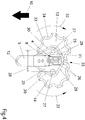
- Fig. 3 and Fig. 4 show the Schreitverumblerung 6 in detail.
- the adapter consists of with the prong 4 screwed fastening tabs 26 and a normal plate to 25. They could also be slightly inclined on both sides.
- the plate is substantially flat, but with an offset 31 corresponding to the axial offset of the discs 13,14, and forms swept on its upstream side and beveled edges for cutting edge 30 and on the downstream side similar trailing edges 29.
- Within the end edges 30 and trailing edges 29 on both sides each provided a receptacle for axes of rotation 27 of the discs 13,14.
- the axes of rotation 27 have a horizontal distance 28 from each other, which is smaller than the diameter of the discs 13,14.
- the direction of rotation of the discs 13,14 is indicated by the arrows 32, and the direction of travel - opposite to the direction of flow of the field soil - by the arrow 10th
- the discs 13,14 are substantially circular and offset in the direction of their axes so far apart that they can overlap each other, corresponding to the smaller distance 28 of their axes 27.
- the contour and surface of the discs 13,14 can be designed very different. In the embodiment shown here, they have razor-sharp edges 33 and recesses 34 distributed over the circumference. Thus, they form a cutting zone 35 when they meet on the outflow side.
- the mode of operation is as follows: The soil soil 11 "flows" against the direction of travel 10 to the Schmalschar 5 and is divided by this into two partial streams. The sub-streams are further deflected by the swept end edges 30 and flow over the outer portion of the top of the discs 13,14. By friction, the discs are rotated.
- the indentations 34 of the two disks 13, 14 improve the thorough mixing of the field soil and, when they meet in the outflow region, form a cutting zone 35, in which carried plant parts are comminuted. From the cutting zone 35, the two disks 13, 14 cooperate in their overlapping area and clean each other.
- the trailing edges 29 of the plate 25 contribute to self-cleaning.
- the overlapping area is not visible in the figures, because covered by the plate 25.
- the self-cleaning of the discs 13,14 prevents an increase in the traction requirement due to constipation and jammed plant parts.
Landscapes
- Life Sciences & Earth Sciences (AREA)
- Engineering & Computer Science (AREA)
- Mechanical Engineering (AREA)
- Soil Sciences (AREA)
- Environmental Sciences (AREA)
- Soil Working Implements (AREA)
Abstract
Description
- Die Erfindung betrifft ein Grubberelement für ein Gerät zur konservierenden Bodenbearbeitung, im Wesentlichen bestehend aus einer Grubberzinke, einer Schmalschar und einer Scharverbreiterung, welche beiderseits der Schmalschar je eine in einem Adapter drehbar gelagerte Scheibe aufweist.
- Es ist aus der Praxis bekannt, Grubberelemente zur besseren Aufbereitung des Ackerbodens mit Flügelscharen auszustatten. Das sind nahe dem unteren Ende des Zinkens seitlich abstehende starre Flügel. Deren Reibungswiderstand ist erheblich, was den Zugkraftbedarf und damit den Treibstoffverbrauch des Zugfahrzeuges erhöht. An den "Anströmkanten" der Flügel bleiben Wurzelreste hängen, was den Zugkraftbedarf weiter erhöht und die Durchmischung der Erde mit Humus und Pflanzenrückständen behindert.
- Aus der Patentschrift
RU 2028740 C1 - Es ist daher Aufgabe der Erfindung, ein gattungsgemäßes Gerät so zu verbessern, dass die genannten negativen Folgen nicht auftreten. Die Scheiben sollen ungehindert und mit möglichst geringem Schlupf vom Ackerboden in Drehung versetzt werden, nicht verstopfen beziehungsweise sogar selbstreinigend sein, und eine gute Durchmischung von Erde und Pflanzenresten erreichen. Dabei soll die erforderliche Zugkraft minimal sein, was dem das Gerät tragenden Ackerschlepper, dessen Treibstoffverbrauch und über verringerte Schadstoffemissionen auch der Umwelt zugutekommt.
- Erfindungsgemäß wird das mit den Merkmalen des 1. Anspruchs erreicht.
- Die Platte des Adapters ist gerade so breit, dass sie die Aufnahmen für die Drehachsen umschließt und den Teil der Scheiben Abdeckt, der sich entgegen der Fahrtrichtung des Gerätes bewegt. Die pfeilartigen Stirnkanten des Adapters lenken die Ackererde mit geringem Zugkraftbedarf seitlich ab. Dadurch, dass der Abstand der Drehachsen kleiner als der Durchmesser der Scheiben ist, überdecken sich die innerhalb der Drehachsen liegenden Bereiche der Scheiben, sodass dort keine entgegen der Drehrichtung der Scheiben wirkende Bodenreibung auftritt. So werden die Scheiben mit minimalem Schlupf und maximalem Drehmoment in gegensinnige Drehung versetzt.
- Um einander teilweise überdecken zu können, sind die Scheiben in Achsrichtung um ihre Dicke gegeneinander versetzt. Dadurch wirken sie auf der Abströmseite zusammen. Sie reinigen einander gegenseitig und zerschneiden an ihnen hängengebliebene Wurzelreste. Sie sind somit selbstreinigend, was ein Ansteigen des Zugkraftbedarfes bei Verunreinigung oder Verstopfung der Scheiben verhindert.
- In einer vorteilhaften Weiterbildung sind die zur Horizontalen geneigten Scheiben höher als die Spitze der Schmalschar angeordnet. Durch die von der Schmalschar gezogene tiefere Furche werden die entgegen der Drehrichtung der Scheiben wirkenden Bodenreibungskräfte weiter vermindert und die durch die geneigten Scheiben geförderte Durchmischung von Erde, Humus und Pflanzenresten weiter verbessert.
- In einer vorteilhaften Ausführungsform ist der Adapter mit der Zinke verschraubt, wobei die Zinke oder der Adapter eine Anzahl Querbohrungen zur wahlweisen Positionierung des Adapters in verschiedenen Stellungen hinsichtlich Neigung und Arbeitstiefen hat. So sind die Grubberelemente der jeweiligen Bodenbeschaffenheit oder sonstigen Anforderungen anpassbar. Bei entsprechender Gestaltung des Adapters kann eine starre Scharverbreiterung nach dem Stand der Technik durch die erfindungsgemäße ersetzt werden. Diese ist somit nachrüstbar.
- Die Scheiben können in verschiedener Form mit verschiedenen Konturen und Durchmessern ausgebildet sein. Als planparallele Kreisscheiben sind sie einfach und billig herzustellen. Vorzugsweise haben sie eine scharfkantige Kontur. Das senkt den Bodenwiderstand und zerschneidet mitgerissene Wurzelteile.
- In Weiterbildung weist die Kontur der Scheiben Einbuchtungen auf. Dadurch wird der Antrieb durch die Bodenreibung, die selbstreinigende Wirkung, und die Durchmischung weiter verbessert.
- Gemäß einem weiteren Aspekt ist die Schmalschar an der Stirnseite der Zinke angebracht und nach oben schließt ein Leitblech an sie an.
- Die Erfindung betrifft auch ein ganzes landwirtschaftliches Gerät zur konservierenden Bodenbearbeitung, das mit den erfindungsgemäßen Grubberzinken ausgestattet ist.
- Im Folgenden wird die Erfindung anhand eines Ausführungsbeispiels des erfindungsgemäßen Grubberelementes beschrieben und erläutert. Es stellen dar:
- Fig.1:
- ein erfindungsgemäßes Grubberelement in axono-metrischer Darstellung, von schräg vorne gesehen,
- Fig.2:
- Detail A in
Fig. 1 vergrößert, von der Seite gesehen und in Arbeitsstellung, - Fig.3:
- Ansicht von vorne gemäß Pfeil III in
Fig. 2 , - Fig.4:
- Schnitt nach IV-IV in
Fig. 3 , vergrößert. - In
Fig. 1 ist der Rahmen einer landwirtschaftlichen Bodenbearbeitungsmaschine durch einen Querträger 1 und einen Längsträger 2 angedeutet. Der Rahmen ist in der üblichen Weise mit einem Traktor verbunden und kann noch andere Bodenbearbeitungswerkzeuge (z.B. Scheibenpflugscharen) aufnehmen. An dem Querträger 1 ist eine Anzahl Grubberelemente 3 in bestimmten Abständen befestigt. Die Befestigung kann beliebig ausgebildet sein, durch Schweißen, vorzugsweise aber mittels eines am Querträger 1 verschiebbaren und feststellbaren Verbindungsstücks 9. - Das Grubberelement 3 besteht aus einer C-förmig gebogenen Grubberzinke 4 mit oben dem Verbindungsstück 9, aus einer an der Stirnseite de Grubberzinke angebrachten Schmalschar 5 und aus einer summarisch mit 6 bezeichneten Scharverbreiterung, die mittels eines Adapters 7 mit der Grubberzinke 4 verbunden ist. An die Schmalschar 5 kann nach oben noch ein Leitblech 8 anschließen.
-
Fig. 2 zeigt das erfindungsgemäße Grubberelement 3 im Einsatz, wobei die Fahrt- und Bearbeitungsrichtung durch den Pfeil 10 angedeutet ist. Die Anströmung der Ackererde erfolgt in der dem Pfeil 10 entgegengesetzten Richtung. Die Schmalschar 5 taucht in den Ackerboden 11 ein, ihre Spitze 12 bestimmt die Bearbeitungstiefe. Die Scharverbreiterung 6 wirkt mittels zweier im Wesentlichen kreisförmiger Scheiben 13,14 außerhalb der Schmalschar 5 auf den Ackerboden ein. Die Scheiben 13,14 sind drehbar im Adapter 7 gelagert und sind bezüglich der Horizontalen um einen spitzen Anstellwinkel 17 geneigt. Ihr tiefster Punkt liegt in einem Abstand 16 über der Spitze 12 der Schmalschar 5. Abstand 16 und Winkel 17 können den Gegebenheiten entsprechend eingestellt werden. Dazu sind beispielsweise im Adapter 7 und in der Zinke 4 eine Anzahl Bohrungen 18,19 für nicht dargestellte Schraubbolzen vorgesehen, die die Verbindung in verschiedenen Stellungen ermöglichen. Die Scheiben hinterlassen einen gelockerten und durchmischten Ackerboden 20, was durch die Kurve 21 angedeutet ist. -
Fig. 3 undFig. 4 zeigen die Scharverbreiterung 6 im Detail. Der Adapter besteht aus mit der Zinke 4 verschraubten Befestigungslaschen 26 und einer dazu normalen Platte 25. Sie könnte auch beiderseits leicht geneigt sein. Die Platte ist im Wesentlichen eben, aber mit einem Versatz 31 entsprechend dem axialen Versatz der Scheiben 13,14, und bildet auf ihrer Anströmseite gepfeilte und zu Schneiden abgeschrägte Stirnkanten 30 und auf der Abströmseite ähnliche Hinterkanten 29. Innerhalb der Stirnkanten 30 und Hinterkanten 29 ist beiderseits je eine Aufnahme für Drehachsen 27 der Scheiben 13,14 vorgesehen. Die Drehachsen 27 haben voneinander einen horizontalen Abstand 28, der kleiner als der Durchmesser der Scheiben 13,14 ist. Der Drehsinn der Scheiben 13,14 ist durch die Bogenpfeile 32 angedeutet, und die Fahrtrichtung - entgegengesetzt der Fließrichtung des Ackerbodens - durch den Pfeil 10. - Die Scheiben 13,14 sind im Wesentlichen kreisförmig und in Richtung ihrer Achsen soweit gegeneinander versetzt, dass sie einander überlappen können, entsprechend dem geringeren Abstand 28 ihrer Achsen 27. Die Kontur und Oberfläche der Scheiben 13,14 kann sehr verschieden gestaltet sein. In der hier gezeigten Ausführungsform haben sie messerscharfe Kanten 33 und über den Umfang verteilte Einbuchtungen 34. So bilden sie bei ihrem Zusammentreffen auf der Abströmseite eine Schneidzone 35.
- Die Arbeitsweise ist wie folgt: Der Ackerboden 11 "fließt" entgegen der Fahrtrichtung 10 auf die Schmalschar 5 zu und wird von dieser in zwei Teilströme geteilt. Die Teilströme werden von den gepfeilten Stirnkanten 30 weiter abgelenkt und fließen über den äußeren Teil der Oberseite der Scheiben 13,14. Durch Reibung werden die Scheiben in Drehung versetzt.
- Wesentlich ist, dass nur die Teile der Scheiben 13,14 außerhalb ihrer Drehachsen 27 mit den Teilströmen in Berührung kommen. Nur dort stimmt die Fließrichtung mit dem Drehsinn 32 überein. Berührung innerhalb der Drehachsen 27 würde dem Drehsinn 32 entgegen wirken. Das wird vor allem durch die Schmalschar 5 und die gepfeilten Kanten 30 verhindert, aber auch durch den Höhenabstand 16 und den Neigungswinkel 17. So werden die Scheiben 13,14 mit einem Minimum an Schlupf und Zugkraftbedarf in Drehung versetzt.
- Die Einbuchtungen 34 der beiden Scheiben 13,14 verbessern die Durchmischung des Ackerbodens und bilden bei ihrem Zusammentreffen im Abströmbereich eine Schneidzone 35, in der mitgeführte Pflanzenteile zerkleinert werden. Ab der Schneidzone 35 wirken die beiden Scheiben 13,14 in ihrem Überlappungsbereich zusammen und reinigen einander gegenseitig. Die Hinterkanten 29 der Platte 25 tragen zur Selbstreinigung bei. Der Überlappungsbereich ist in den Figuren nicht sichtbar, weil von der Platte 25 abgedeckt. Die Selbstreinigung der Scheiben 13,14 verhindert ein Ansteigen des Zugkraftbedarfes durch Verstopfung und verklemmte Pflanzenteile.
- Von der beschriebenen Ausführungsform kann im Umfang der Patentansprüche abgewichen werden. Insgesamt wird die gestellte Aufgabe so vollständig gelöst.
Claims (9)
- Grubberelement für ein Gerät zur konservierenden Bodenbearbeitung, im Wesentlichen bestehend aus einer Grubberzinke(4), einer Schmalschar (5)und einer Scharverbreiterung (6), welche beiderseits der Schmalschar (5)je eine in einem Adapter (7) drehbar gelagerte Scheibe(13,14)aufweist, dadurch gekennzeichnet, dassa) der Adapter (7) eine Platte (25) mit pfeilartig geneigten Stirnkanten (30) bildet, welche Platte Aufnahmen für zu ihr normale Drehachsen (27) für die Scheiben (13,14) aufweist, deren Abstand (28) kleiner als der Durchmesser der einzelnen Scheiben (13,14) ist, und dassb) die Scheiben (13,14) in Richtung ihrer Drehachsen (27) um ihre Dicke gegeneinander versetzt sind, sodass sie einander in dem von der Platte (25) überdeckten Bereich überschneiden.
- Grubberelement nach Anspruch 1, dadurch gekennzeichnet, dass die Platte (25) und die zur Horizontalen geneigten Scheiben (13,14) höher als die Spitze (12) der Schmalschar (5) angeordnet sind.
- Grubberelement nach Anspruch 1, dadurch gekennzeichnet, dass der Adapter (7) mindestens eine zur Platte normale Befestigungslasche (26) zur Verbindung mit der Zinke (4) mittels Schraubbolzen (n.d.) aufweist, und die Zinke (4) und/oder der Adapter (7) eine Anzahl Querbohrungen (18,19) zur wahlweisen Positionierung des Adapters (7) in verschiedenen Stellungen hat.
- Grubberelement nach Anspruch 1 oder 2, dadurch gekennzeichnet, dass die Scheiben (13,14) planparallele Kreisscheiben sind.
- Grubberelement nach Anspruch 1 oder 2, dadurch gekennzeichnet, dass die Scheiben (13,14) eine Scharfkantige Kontur (33) aufweisen.
- Grubberelement nach Anspruch 1, dadurch gekennzeichnet, dass die Scheiben (13,14) eine gewölbte und/oder gerillte Oberfläche aufweisen.
- Grubberelement nach Anspruch 1, dadurch gekennzeichnet, dass die Kontur (33) der Scheiben Einbuchtungen (34) aufweist.
- Grubberelement nach Anspruch 1 oder 2, dadurch gekennzeichnet, dass die Schmalschar (5) an der Stirnseite der Zinke (4) angebracht ist und nach oben ein Leitblech (8) an die Schmalschar (5) anschließt.
- Landwirtschaftliches Gerät zur konservierenden Bodenbearbeitung, versehen mit Grubberzinken nach einem der Ansprüche 1 bis 8.
Priority Applications (1)
| Application Number | Priority Date | Filing Date | Title |
|---|---|---|---|
| PL17000159T PL3222128T3 (pl) | 2016-02-15 | 2017-02-01 | Element kultywatora dla urządzenia do konserwującej uprawy roli oraz zawierające go urządzenie rolnicze |
Applications Claiming Priority (1)
| Application Number | Priority Date | Filing Date | Title |
|---|---|---|---|
| ATA75/2016A AT517586B1 (de) | 2016-02-15 | 2016-02-15 | Grubberelement für ein Gerät zur konservierenden Bodenbearbeitung und landwirtschaftliches Gerät |
Publications (2)
| Publication Number | Publication Date |
|---|---|
| EP3222128A1 true EP3222128A1 (de) | 2017-09-27 |
| EP3222128B1 EP3222128B1 (de) | 2018-10-24 |
Family
ID=57960224
Family Applications (1)
| Application Number | Title | Priority Date | Filing Date |
|---|---|---|---|
| EP17000159.8A Active EP3222128B1 (de) | 2016-02-15 | 2017-02-01 | Grubberelement für ein gerät zur konservierenden bodenbearbeitung und landwirtschaftliches gerät damit |
Country Status (5)
| Country | Link |
|---|---|
| EP (1) | EP3222128B1 (de) |
| AT (1) | AT517586B1 (de) |
| ES (1) | ES2706526T3 (de) |
| HU (1) | HUE041813T2 (de) |
| PL (1) | PL3222128T3 (de) |
Cited By (5)
| Publication number | Priority date | Publication date | Assignee | Title |
|---|---|---|---|---|
| EP3659412A1 (de) * | 2018-11-27 | 2020-06-03 | Thyregod A/S | Grubber und verfahren zum verbinden eines bodenwerkzeugs mit einer werkzeugtragestruktur |
| CN111386808A (zh) * | 2020-04-22 | 2020-07-10 | 西北农林科技大学 | 一种干湿土分层开沟覆土免耕播种装置 |
| CN114568050A (zh) * | 2022-03-02 | 2022-06-03 | 北京晟纪信息科技有限公司 | 农业数字耕地一体化应用装置 |
| RU212656U1 (ru) * | 2022-03-15 | 2022-08-02 | Федеральное государственное бюджетное образовательное учреждение высшего образования "Брянский государственный аграрный университет" | Плоскорежущий рабочий орган |
| WO2022260641A1 (en) * | 2021-06-11 | 2022-12-15 | Eden Gizem | Soil working machine in chisel form equipped with circular elements |
Families Citing this family (2)
| Publication number | Priority date | Publication date | Assignee | Title |
|---|---|---|---|---|
| FR3149468B1 (fr) * | 2023-06-09 | 2025-08-15 | Carbure Tech Sas | Dispositif de fissuration à aileron tracte |
| AT528025B1 (de) * | 2024-07-05 | 2025-09-15 | Boehlerit Gmbh & Co Kg | Leichtgewichtige Gänsefußschar |
Citations (4)
| Publication number | Priority date | Publication date | Assignee | Title |
|---|---|---|---|---|
| NL103987C (de) * | 1900-01-01 | |||
| US2396132A (en) * | 1942-10-08 | 1946-03-05 | Larkin R Shaffer | Cultivator tool |
| FR2382166A1 (fr) * | 1977-03-04 | 1978-09-29 | Ransomes Sims & Jefferies Ltd | Outil de dechaumage |
| RU2028740C1 (ru) * | 1990-09-27 | 1995-02-20 | Александр Анатольевич Шишов | Почвообрабатывающее орудие |
Family Cites Families (5)
| Publication number | Priority date | Publication date | Assignee | Title |
|---|---|---|---|---|
| SU451417A1 (ru) * | 1973-03-02 | 1974-11-30 | Целинный Научно-Исследовательский Институт Механизации И Электрификации Сельского Хозяйства | Рабочий орган почвообрабатывающего оруди |
| SU1178338A2 (ru) * | 1984-03-05 | 1985-09-15 | Uchaev Yurij F | Плоскорежущий рабочий орган |
| FR2623049B1 (fr) * | 1987-11-13 | 1991-05-17 | Maysonnave Roger | Dispositif de preparation du sol a lames rotatives non entrainees mecaniquement |
| SU1595360A1 (ru) * | 1988-11-21 | 1990-09-30 | Днепропетровский сельскохозяйственный институт | Рабочий орган почвообрабатывающего оруди |
| DE4124358C2 (de) * | 1991-07-23 | 1994-03-10 | Hans Hofmann | Ein- oder mehrreihige Bodenbearbeitungsmaschine |
-
2016
- 2016-02-15 AT ATA75/2016A patent/AT517586B1/de active
-
2017
- 2017-02-01 HU HUE17000159A patent/HUE041813T2/hu unknown
- 2017-02-01 PL PL17000159T patent/PL3222128T3/pl unknown
- 2017-02-01 ES ES17000159T patent/ES2706526T3/es active Active
- 2017-02-01 EP EP17000159.8A patent/EP3222128B1/de active Active
Patent Citations (4)
| Publication number | Priority date | Publication date | Assignee | Title |
|---|---|---|---|---|
| NL103987C (de) * | 1900-01-01 | |||
| US2396132A (en) * | 1942-10-08 | 1946-03-05 | Larkin R Shaffer | Cultivator tool |
| FR2382166A1 (fr) * | 1977-03-04 | 1978-09-29 | Ransomes Sims & Jefferies Ltd | Outil de dechaumage |
| RU2028740C1 (ru) * | 1990-09-27 | 1995-02-20 | Александр Анатольевич Шишов | Почвообрабатывающее орудие |
Cited By (6)
| Publication number | Priority date | Publication date | Assignee | Title |
|---|---|---|---|---|
| EP3659412A1 (de) * | 2018-11-27 | 2020-06-03 | Thyregod A/S | Grubber und verfahren zum verbinden eines bodenwerkzeugs mit einer werkzeugtragestruktur |
| CN111386808A (zh) * | 2020-04-22 | 2020-07-10 | 西北农林科技大学 | 一种干湿土分层开沟覆土免耕播种装置 |
| WO2022260641A1 (en) * | 2021-06-11 | 2022-12-15 | Eden Gizem | Soil working machine in chisel form equipped with circular elements |
| CN114568050A (zh) * | 2022-03-02 | 2022-06-03 | 北京晟纪信息科技有限公司 | 农业数字耕地一体化应用装置 |
| RU212656U1 (ru) * | 2022-03-15 | 2022-08-02 | Федеральное государственное бюджетное образовательное учреждение высшего образования "Брянский государственный аграрный университет" | Плоскорежущий рабочий орган |
| RU219672U1 (ru) * | 2022-12-29 | 2023-07-31 | Федеральное государственное бюджетное образовательное учреждение высшего образования "Брянский государственный аграрный университет" | Рабочий орган культиватора для междурядной обработки гребней |
Also Published As
| Publication number | Publication date |
|---|---|
| HUE041813T2 (hu) | 2019-05-28 |
| AT517586B1 (de) | 2017-03-15 |
| AT517586A4 (de) | 2017-03-15 |
| PL3222128T3 (pl) | 2019-03-29 |
| ES2706526T3 (es) | 2019-03-29 |
| EP3222128B1 (de) | 2018-10-24 |
Similar Documents
| Publication | Publication Date | Title |
|---|---|---|
| EP3222128B1 (de) | Grubberelement für ein gerät zur konservierenden bodenbearbeitung und landwirtschaftliches gerät damit | |
| DE2657002B2 (de) | Fräswerkzeuge für Sämaschinen | |
| DE1279993B (de) | Bodenbearbeitungsmaschine | |
| DE2030448A1 (de) | Bodenbearbeitungsmaschine | |
| DE2932695A1 (de) | Bodenbearbeitungsmaschine | |
| DE3541490A1 (de) | Bodenbearbeitungsmaschine | |
| AT393430B (de) | Umkehrbar bzw. gegenlaeufig rotierende bodenbearbeitungsvorrichtung | |
| DE3587357T2 (de) | Bodenbearbeitungsmaschine. | |
| DE2510011A1 (de) | Bodenbearbeitungsmaschine | |
| DE3038046C2 (de) | Vorrichtung zum Bodenbearbeiten, insbesondere für Garten- und Parkanlagen | |
| DE3446312C2 (de) | ||
| DE2508481A1 (de) | Bodenbearbeitungsmaschine | |
| CH630225A5 (de) | Kreiselegge. | |
| EP0260643A2 (de) | Vertikutiermesser für ein Vertikutiergerät | |
| DE3334727A1 (de) | Kombinierte bodenbearbeitungsmaschine | |
| DE2504859A1 (de) | Zinken fuer eine bodenbearbeitungsmaschine | |
| DE3334662C2 (de) | Schlepperbetriebene Bodenbearbeitungsmaschine | |
| DE202017101979U1 (de) | Landwirtschaftliches Bodenbearbeitungsgerät | |
| DE2508211A1 (de) | Bodenbearbeitungsmaschine | |
| DE3626456A1 (de) | Strohhaecksler | |
| EP0472129B1 (de) | Bodenbearbeitungsmaschine | |
| DE2849868C3 (de) | Bodenbearbeitungsmaschine | |
| DE3525167C2 (de) | ||
| AT227014B (de) | Mähmaschine | |
| EP0224708B1 (de) | Zinken für eine Bodenbearbeitungsmaschine |
Legal Events
| Date | Code | Title | Description |
|---|---|---|---|
| PUAI | Public reference made under article 153(3) epc to a published international application that has entered the european phase |
Free format text: ORIGINAL CODE: 0009012 |
|
| STAA | Information on the status of an ep patent application or granted ep patent |
Free format text: STATUS: THE APPLICATION HAS BEEN PUBLISHED |
|
| AK | Designated contracting states |
Kind code of ref document: A1 Designated state(s): AL AT BE BG CH CY CZ DE DK EE ES FI FR GB GR HR HU IE IS IT LI LT LU LV MC MK MT NL NO PL PT RO RS SE SI SK SM TR |
|
| AX | Request for extension of the european patent |
Extension state: BA ME |
|
| STAA | Information on the status of an ep patent application or granted ep patent |
Free format text: STATUS: REQUEST FOR EXAMINATION WAS MADE |
|
| 17P | Request for examination filed |
Effective date: 20180125 |
|
| GRAP | Despatch of communication of intention to grant a patent |
Free format text: ORIGINAL CODE: EPIDOSNIGR1 |
|
| STAA | Information on the status of an ep patent application or granted ep patent |
Free format text: STATUS: GRANT OF PATENT IS INTENDED |
|
| INTG | Intention to grant announced |
Effective date: 20180405 |
|
| GRAS | Grant fee paid |
Free format text: ORIGINAL CODE: EPIDOSNIGR3 |
|
| GRAA | (expected) grant |
Free format text: ORIGINAL CODE: 0009210 |
|
| STAA | Information on the status of an ep patent application or granted ep patent |
Free format text: STATUS: THE PATENT HAS BEEN GRANTED |
|
| AK | Designated contracting states |
Kind code of ref document: B1 Designated state(s): AL AT BE BG CH CY CZ DE DK EE ES FI FR GB GR HR HU IE IS IT LI LT LU LV MC MK MT NL NO PL PT RO RS SE SI SK SM TR |
|
| REG | Reference to a national code |
Ref country code: CH Ref legal event code: EP |
|
| REG | Reference to a national code |
Ref country code: IE Ref legal event code: FG4D Free format text: LANGUAGE OF EP DOCUMENT: GERMAN |
|
| REG | Reference to a national code |
Ref country code: AT Ref legal event code: REF Ref document number: 1055562 Country of ref document: AT Kind code of ref document: T Effective date: 20181115 |
|
| REG | Reference to a national code |
Ref country code: DE Ref legal event code: R096 Ref document number: 502017000269 Country of ref document: DE |
|
| REG | Reference to a national code |
Ref country code: CH Ref legal event code: NV Representative=s name: DENNEMEYER AG, CH |
|
| REG | Reference to a national code |
Ref country code: RO Ref legal event code: EPE |
|
| REG | Reference to a national code |
Ref country code: NL Ref legal event code: FP |
|
| REG | Reference to a national code |
Ref country code: LT Ref legal event code: MG4D |
|
| REG | Reference to a national code |
Ref country code: NO Ref legal event code: T2 Effective date: 20181024 |
|
| REG | Reference to a national code |
Ref country code: ES Ref legal event code: FG2A Ref document number: 2706526 Country of ref document: ES Kind code of ref document: T3 Effective date: 20190329 |
|
| PG25 | Lapsed in a contracting state [announced via postgrant information from national office to epo] |
Ref country code: HR Free format text: LAPSE BECAUSE OF FAILURE TO SUBMIT A TRANSLATION OF THE DESCRIPTION OR TO PAY THE FEE WITHIN THE PRESCRIBED TIME-LIMIT Effective date: 20181024 Ref country code: LT Free format text: LAPSE BECAUSE OF FAILURE TO SUBMIT A TRANSLATION OF THE DESCRIPTION OR TO PAY THE FEE WITHIN THE PRESCRIBED TIME-LIMIT Effective date: 20181024 Ref country code: LV Free format text: LAPSE BECAUSE OF FAILURE TO SUBMIT A TRANSLATION OF THE DESCRIPTION OR TO PAY THE FEE WITHIN THE PRESCRIBED TIME-LIMIT Effective date: 20181024 Ref country code: IS Free format text: LAPSE BECAUSE OF FAILURE TO SUBMIT A TRANSLATION OF THE DESCRIPTION OR TO PAY THE FEE WITHIN THE PRESCRIBED TIME-LIMIT Effective date: 20190224 Ref country code: BG Free format text: LAPSE BECAUSE OF FAILURE TO SUBMIT A TRANSLATION OF THE DESCRIPTION OR TO PAY THE FEE WITHIN THE PRESCRIBED TIME-LIMIT Effective date: 20190124 |
|
| REG | Reference to a national code |
Ref country code: HU Ref legal event code: AG4A Ref document number: E041813 Country of ref document: HU |
|
| PG25 | Lapsed in a contracting state [announced via postgrant information from national office to epo] |
Ref country code: GR Free format text: LAPSE BECAUSE OF FAILURE TO SUBMIT A TRANSLATION OF THE DESCRIPTION OR TO PAY THE FEE WITHIN THE PRESCRIBED TIME-LIMIT Effective date: 20190125 Ref country code: RS Free format text: LAPSE BECAUSE OF FAILURE TO SUBMIT A TRANSLATION OF THE DESCRIPTION OR TO PAY THE FEE WITHIN THE PRESCRIBED TIME-LIMIT Effective date: 20181024 Ref country code: SE Free format text: LAPSE BECAUSE OF FAILURE TO SUBMIT A TRANSLATION OF THE DESCRIPTION OR TO PAY THE FEE WITHIN THE PRESCRIBED TIME-LIMIT Effective date: 20181024 Ref country code: PT Free format text: LAPSE BECAUSE OF FAILURE TO SUBMIT A TRANSLATION OF THE DESCRIPTION OR TO PAY THE FEE WITHIN THE PRESCRIBED TIME-LIMIT Effective date: 20190224 Ref country code: AL Free format text: LAPSE BECAUSE OF FAILURE TO SUBMIT A TRANSLATION OF THE DESCRIPTION OR TO PAY THE FEE WITHIN THE PRESCRIBED TIME-LIMIT Effective date: 20181024 |
|
| REG | Reference to a national code |
Ref country code: SK Ref legal event code: T3 Ref document number: E 29886 Country of ref document: SK |
|
| REG | Reference to a national code |
Ref country code: DE Ref legal event code: R097 Ref document number: 502017000269 Country of ref document: DE |
|
| PG25 | Lapsed in a contracting state [announced via postgrant information from national office to epo] |
Ref country code: DK Free format text: LAPSE BECAUSE OF FAILURE TO SUBMIT A TRANSLATION OF THE DESCRIPTION OR TO PAY THE FEE WITHIN THE PRESCRIBED TIME-LIMIT Effective date: 20181024 |
|
| PG25 | Lapsed in a contracting state [announced via postgrant information from national office to epo] |
Ref country code: SM Free format text: LAPSE BECAUSE OF FAILURE TO SUBMIT A TRANSLATION OF THE DESCRIPTION OR TO PAY THE FEE WITHIN THE PRESCRIBED TIME-LIMIT Effective date: 20181024 Ref country code: EE Free format text: LAPSE BECAUSE OF FAILURE TO SUBMIT A TRANSLATION OF THE DESCRIPTION OR TO PAY THE FEE WITHIN THE PRESCRIBED TIME-LIMIT Effective date: 20181024 |
|
| PLBE | No opposition filed within time limit |
Free format text: ORIGINAL CODE: 0009261 |
|
| STAA | Information on the status of an ep patent application or granted ep patent |
Free format text: STATUS: NO OPPOSITION FILED WITHIN TIME LIMIT |
|
| 26N | No opposition filed |
Effective date: 20190725 |
|
| PG25 | Lapsed in a contracting state [announced via postgrant information from national office to epo] |
Ref country code: MC Free format text: LAPSE BECAUSE OF FAILURE TO SUBMIT A TRANSLATION OF THE DESCRIPTION OR TO PAY THE FEE WITHIN THE PRESCRIBED TIME-LIMIT Effective date: 20181024 Ref country code: SI Free format text: LAPSE BECAUSE OF FAILURE TO SUBMIT A TRANSLATION OF THE DESCRIPTION OR TO PAY THE FEE WITHIN THE PRESCRIBED TIME-LIMIT Effective date: 20181024 Ref country code: LU Free format text: LAPSE BECAUSE OF NON-PAYMENT OF DUE FEES Effective date: 20190201 |
|
| REG | Reference to a national code |
Ref country code: IE Ref legal event code: MM4A |
|
| PG25 | Lapsed in a contracting state [announced via postgrant information from national office to epo] |
Ref country code: IE Free format text: LAPSE BECAUSE OF NON-PAYMENT OF DUE FEES Effective date: 20190201 |
|
| PG25 | Lapsed in a contracting state [announced via postgrant information from national office to epo] |
Ref country code: TR Free format text: LAPSE BECAUSE OF FAILURE TO SUBMIT A TRANSLATION OF THE DESCRIPTION OR TO PAY THE FEE WITHIN THE PRESCRIBED TIME-LIMIT Effective date: 20181024 |
|
| PG25 | Lapsed in a contracting state [announced via postgrant information from national office to epo] |
Ref country code: MT Free format text: LAPSE BECAUSE OF FAILURE TO SUBMIT A TRANSLATION OF THE DESCRIPTION OR TO PAY THE FEE WITHIN THE PRESCRIBED TIME-LIMIT Effective date: 20181024 |
|
| PG25 | Lapsed in a contracting state [announced via postgrant information from national office to epo] |
Ref country code: CY Free format text: LAPSE BECAUSE OF FAILURE TO SUBMIT A TRANSLATION OF THE DESCRIPTION OR TO PAY THE FEE WITHIN THE PRESCRIBED TIME-LIMIT Effective date: 20181024 |
|
| PG25 | Lapsed in a contracting state [announced via postgrant information from national office to epo] |
Ref country code: MK Free format text: LAPSE BECAUSE OF FAILURE TO SUBMIT A TRANSLATION OF THE DESCRIPTION OR TO PAY THE FEE WITHIN THE PRESCRIBED TIME-LIMIT Effective date: 20181024 |
|
| REG | Reference to a national code |
Ref country code: AT Ref legal event code: MM01 Ref document number: 1055562 Country of ref document: AT Kind code of ref document: T Effective date: 20220201 |
|
| PG25 | Lapsed in a contracting state [announced via postgrant information from national office to epo] |
Ref country code: AT Free format text: LAPSE BECAUSE OF NON-PAYMENT OF DUE FEES Effective date: 20220201 |
|
| PGFP | Annual fee paid to national office [announced via postgrant information from national office to epo] |
Ref country code: NL Payment date: 20240220 Year of fee payment: 8 |
|
| PGFP | Annual fee paid to national office [announced via postgrant information from national office to epo] |
Ref country code: RO Payment date: 20240220 Year of fee payment: 8 Ref country code: FI Payment date: 20240219 Year of fee payment: 8 Ref country code: GB Payment date: 20240222 Year of fee payment: 8 |
|
| PGFP | Annual fee paid to national office [announced via postgrant information from national office to epo] |
Ref country code: NO Payment date: 20240220 Year of fee payment: 8 Ref country code: IT Payment date: 20240229 Year of fee payment: 8 Ref country code: BE Payment date: 20240219 Year of fee payment: 8 |
|
| PGFP | Annual fee paid to national office [announced via postgrant information from national office to epo] |
Ref country code: HU Payment date: 20250224 Year of fee payment: 9 |
|
| PGFP | Annual fee paid to national office [announced via postgrant information from national office to epo] |
Ref country code: ES Payment date: 20250318 Year of fee payment: 9 |
|
| REG | Reference to a national code |
Ref country code: NL Ref legal event code: MM Effective date: 20250301 |
|
| PG25 | Lapsed in a contracting state [announced via postgrant information from national office to epo] |
Ref country code: FI Free format text: LAPSE BECAUSE OF NON-PAYMENT OF DUE FEES Effective date: 20250201 |
|
| PG25 | Lapsed in a contracting state [announced via postgrant information from national office to epo] |
Ref country code: NO Free format text: LAPSE BECAUSE OF NON-PAYMENT OF DUE FEES Effective date: 20250228 |
|
| PG25 | Lapsed in a contracting state [announced via postgrant information from national office to epo] |
Ref country code: RO Free format text: LAPSE BECAUSE OF NON-PAYMENT OF DUE FEES Effective date: 20250201 |
|
| GBPC | Gb: european patent ceased through non-payment of renewal fee |
Effective date: 20250201 |
|
| PG25 | Lapsed in a contracting state [announced via postgrant information from national office to epo] |
Ref country code: NL Free format text: LAPSE BECAUSE OF NON-PAYMENT OF DUE FEES Effective date: 20250301 |
|
| REG | Reference to a national code |
Ref country code: BE Ref legal event code: MM Effective date: 20250228 |
|
| PG25 | Lapsed in a contracting state [announced via postgrant information from national office to epo] |
Ref country code: GB Free format text: LAPSE BECAUSE OF NON-PAYMENT OF DUE FEES Effective date: 20250201 |
|
| PG25 | Lapsed in a contracting state [announced via postgrant information from national office to epo] |
Ref country code: IT Free format text: LAPSE BECAUSE OF NON-PAYMENT OF DUE FEES Effective date: 20250201 |
|
| PG25 | Lapsed in a contracting state [announced via postgrant information from national office to epo] |
Ref country code: BE Free format text: LAPSE BECAUSE OF NON-PAYMENT OF DUE FEES Effective date: 20250228 |
|
| REG | Reference to a national code |
Ref country code: CH Ref legal event code: U11 Free format text: ST27 STATUS EVENT CODE: U-0-0-U10-U11 (AS PROVIDED BY THE NATIONAL OFFICE) Effective date: 20260301 |
|
| PGFP | Annual fee paid to national office [announced via postgrant information from national office to epo] |
Ref country code: DE Payment date: 20260217 Year of fee payment: 10 |
|
| PGFP | Annual fee paid to national office [announced via postgrant information from national office to epo] |
Ref country code: FR Payment date: 20260223 Year of fee payment: 10 |
|
| PGFP | Annual fee paid to national office [announced via postgrant information from national office to epo] |
Ref country code: CH Payment date: 20260301 Year of fee payment: 10 Ref country code: CZ Payment date: 20260127 Year of fee payment: 10 |
|
| PGFP | Annual fee paid to national office [announced via postgrant information from national office to epo] |
Ref country code: PL Payment date: 20260126 Year of fee payment: 10 |
|
| PGFP | Annual fee paid to national office [announced via postgrant information from national office to epo] |
Ref country code: SK Payment date: 20260127 Year of fee payment: 10 |