EP3219895A1 - Schiebetüranordnung und schiebeflügel einer schiebetüranordnung - Google Patents
Schiebetüranordnung und schiebeflügel einer schiebetüranordnung Download PDFInfo
- Publication number
- EP3219895A1 EP3219895A1 EP17161656.8A EP17161656A EP3219895A1 EP 3219895 A1 EP3219895 A1 EP 3219895A1 EP 17161656 A EP17161656 A EP 17161656A EP 3219895 A1 EP3219895 A1 EP 3219895A1
- Authority
- EP
- European Patent Office
- Prior art keywords
- support
- sliding
- surface element
- sliding wing
- edge profile
- Prior art date
- Legal status (The legal status is an assumption and is not a legal conclusion. Google has not performed a legal analysis and makes no representation as to the accuracy of the status listed.)
- Granted
Links
Images



Classifications
-
- E—FIXED CONSTRUCTIONS
- E06—DOORS, WINDOWS, SHUTTERS, OR ROLLER BLINDS IN GENERAL; LADDERS
- E06B—FIXED OR MOVABLE CLOSURES FOR OPENINGS IN BUILDINGS, VEHICLES, FENCES OR LIKE ENCLOSURES IN GENERAL, e.g. DOORS, WINDOWS, BLINDS, GATES
- E06B3/00—Window sashes, door leaves, or like elements for closing wall or like openings; Layout of fixed or moving closures, e.g. windows in wall or like openings; Features of rigidly-mounted outer frames relating to the mounting of wing frames
- E06B3/54—Fixing of glass panes or like plates
- E06B3/5454—Fixing of glass panes or like plates inside U-shaped section members
-
- E—FIXED CONSTRUCTIONS
- E06—DOORS, WINDOWS, SHUTTERS, OR ROLLER BLINDS IN GENERAL; LADDERS
- E06B—FIXED OR MOVABLE CLOSURES FOR OPENINGS IN BUILDINGS, VEHICLES, FENCES OR LIKE ENCLOSURES IN GENERAL, e.g. DOORS, WINDOWS, BLINDS, GATES
- E06B3/00—Window sashes, door leaves, or like elements for closing wall or like openings; Layout of fixed or moving closures, e.g. windows in wall or like openings; Features of rigidly-mounted outer frames relating to the mounting of wing frames
- E06B3/04—Wing frames not characterised by the manner of movement
- E06B3/263—Frames with special provision for insulation
- E06B3/26347—Frames with special provision for insulation specially adapted for sliding doors or windows
-
- E—FIXED CONSTRUCTIONS
- E06—DOORS, WINDOWS, SHUTTERS, OR ROLLER BLINDS IN GENERAL; LADDERS
- E06B—FIXED OR MOVABLE CLOSURES FOR OPENINGS IN BUILDINGS, VEHICLES, FENCES OR LIKE ENCLOSURES IN GENERAL, e.g. DOORS, WINDOWS, BLINDS, GATES
- E06B3/00—Window sashes, door leaves, or like elements for closing wall or like openings; Layout of fixed or moving closures, e.g. windows in wall or like openings; Features of rigidly-mounted outer frames relating to the mounting of wing frames
- E06B3/54—Fixing of glass panes or like plates
- E06B3/5409—Means for locally spacing the pane from the surrounding frame
-
- E—FIXED CONSTRUCTIONS
- E06—DOORS, WINDOWS, SHUTTERS, OR ROLLER BLINDS IN GENERAL; LADDERS
- E06B—FIXED OR MOVABLE CLOSURES FOR OPENINGS IN BUILDINGS, VEHICLES, FENCES OR LIKE ENCLOSURES IN GENERAL, e.g. DOORS, WINDOWS, BLINDS, GATES
- E06B3/00—Window sashes, door leaves, or like elements for closing wall or like openings; Layout of fixed or moving closures, e.g. windows in wall or like openings; Features of rigidly-mounted outer frames relating to the mounting of wing frames
- E06B3/04—Wing frames not characterised by the manner of movement
- E06B3/263—Frames with special provision for insulation
- E06B3/2632—Frames with special provision for insulation with arrangements reducing the heat transmission, other than an interruption in a metal section
- E06B2003/26332—Arrangements reducing the heat transfer in the glazing rabbet or the space between the wing and the casing frame
-
- E—FIXED CONSTRUCTIONS
- E06—DOORS, WINDOWS, SHUTTERS, OR ROLLER BLINDS IN GENERAL; LADDERS
- E06B—FIXED OR MOVABLE CLOSURES FOR OPENINGS IN BUILDINGS, VEHICLES, FENCES OR LIKE ENCLOSURES IN GENERAL, e.g. DOORS, WINDOWS, BLINDS, GATES
- E06B3/00—Window sashes, door leaves, or like elements for closing wall or like openings; Layout of fixed or moving closures, e.g. windows in wall or like openings; Features of rigidly-mounted outer frames relating to the mounting of wing frames
- E06B3/32—Arrangements of wings characterised by the manner of movement; Arrangements of movable wings in openings; Features of wings or frames relating solely to the manner of movement of the wing
- E06B3/34—Arrangements of wings characterised by the manner of movement; Arrangements of movable wings in openings; Features of wings or frames relating solely to the manner of movement of the wing with only one kind of movement
- E06B3/42—Sliding wings; Details of frames with respect to guiding
- E06B3/46—Horizontally-sliding wings
- E06B3/4609—Horizontally-sliding wings for windows
Definitions
- the invention relates to a sliding sash of a sliding door arrangement, in which support rollers for the sliding sash are stationary.
- the sliding leaf has a surface element in which an edge profile is placed on at least one end face facing the support rollers.
- the invention further relates to a sliding door assembly with a bottom profile with fixed support rollers and at least one sliding sash.
- the aforementioned sliding door assembly allows for a given size of a building opening, the use of a larger area element, such as a larger insulating glass pane.
- a visually elegant appearance of the sliding sash is made possible, since this has only a very narrow edge profile compared to a supporting frame.
- the support rollers are preferably mounted in a floor profile, which is sunk in a floor of a building and thus mounted flush with the floor.
- Such a sliding door arrangement is for example from the document WO 2010/024703 A1 known.
- a U-shaped edge profile is placed on an insulating glass as a surface element, wherein the edge profile has on its side facing away from the surface element raceways, with which it rests on the support rollers.
- the surface elements are usually supported only at a few selected points by so-called glass blocks in the frame.
- the edge profiles are not alone capable of distributing the weight forces of the surface element which are selectively acting on the support rollers laterally along the end face of the surface element.
- the surface element itself is used for receiving and distributing the punctual forces.
- the surface element is located directly on edge profile and is optionally glued to this.
- a uniform force transmission between the edge profile and the surface element is to be achieved with good tolerance compensation.
- An inventive sliding leaf of the type mentioned above is characterized in that between the end face of the surface element and the edge profile extending in the longitudinal direction of the edge profile support strip is inserted from plastic.
- the edge profile is preferably a metal profile or a plastic profile of a hard plastic such as PVC (polyvinyl chloride), possibly with glass fiber reinforcement.
- the support bar is softer and preferably has a Shor A hardness of 60 to 80. It can be easily pressed in and thus produce a thickness compensation. At the same time, it has a uniform thickness, which leads to a good and uniform fit of the edge profile on the surface element.
- the support strip extends in one or more parts substantially over the entire length of the end face of the surface element.
- the support supports the front page of the surface element thereby also over its entire width.
- the weight of the entire surface element can be transmitted as evenly as possible to the edge profile.
- the support does not support the end face of the surface element over the entire surface but rather in a plurality of support points distributed as uniformly as possible. Due to the not full-surface design of the pressure on the support at the support points is increased. Even when using a relatively hard plastic for the support this leads to a sufficient deformability at the support points, so that a thickness compensation is guaranteed to compensate for unevenness of the surface element on the front page.
- the support may comprise, for example, at least one web extending in the form of a wave, wherein the web may, for example, have a rectangular cross-section.
- the support may be ladder-shaped with at least one longitudinal web extending in the longitudinal direction and a plurality of transverse webs.
- the support can be varied by swaging or pulling it in the longitudinal direction in its width. This may, for example, be well implemented on an overlay comprising a rippled web.
- the support can be adapted in its width to different thickness surface elements and does not need to be made separately and kept in all required widths. In contrast to the width, the length can be adjusted easily.
- the support has a structured surface on its upper and / or lower side.
- the structured surface may preferably be provided with a serrated structure.
- the deformability of the support can be additionally controlled.
- the point pointed or less acute triangular structures or deep or less deep structures
- Deformability of the support can be adjusted for a given plastic material.
- a sliding door assembly according to the invention has at least one bottom profile, are arranged stationary in the support rollers, and at least one slidably guided on the support rollers such sliding sash. This results in the advantages mentioned in connection with the sliding leaf.
- Fig. 1 shows a schematic partially sectioned side view of a sliding door assembly in which a sliding panel according to the application is used.
- a bottom profile 20 is embedded in a recess 2, in which at regular intervals support rollers 24 are rotatably mounted stationary.
- two sliding sash 10 are placed, each having a surface element 11, in particular an insulating glass pane having.
- a surface element 11 in particular an insulating glass pane having.
- the sliding sash 10 is shown offset upwards.
- the surface elements 11 are bordered at their lower, the support rollers 24 facing end side of each edge profile 12. At the respective three other end faces more edge profiles 13 are arranged. With regard to its cross section, the further edge profiles 13 may be the same or similar to the edge profile 12 arranged below.
- An edge profile 12 and three further edge profiles 13 comprise each surface element 11 as a frame, which is not self-supporting and only in conjunction with the surface element 11 has the necessary stability.
- the sliding leaf 10 are placed with its lower edge profile 12 on the support rollers 24.
- guides are provided which prevent tilting of the sliding sash 10 from its vertical position.
- the sliding sash 10 can run directly on the support rollers 24 with the lower edge profile 12. Alternatively, a separate running profile, which provides the actual tread, be attached to the edge profile 12.
- An according to the application sliding door assembly may have one or more such sliding sash 10. If several mutually displaceable sliding panels 10 are provided, these are arranged in different levels one behind the other, so that they can be moved past each other. Accordingly, support rollers 24 are also arranged in different, adjacent in the ground plane lines one behind the other.
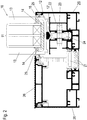
- Fig. 2 shows a section through a bottom profile 20 and a section of a mounted sliding leaf 10 in a further embodiment of a sliding door assembly.
- movable sliding leaf 10 is provided, at least in the area of the illustrated sectional plane.
- two adjacent identical and mirror-inverted floor profiles 20 are still embedded in the ground, not shown here.
- the two floor profiles 20 are coupled together via insulating webs 21. They are mounted by not visible in this figure anchors in a depression of the soil.
- Fig. 2 arranged on the right side bottom profile 20 has an inserted support roller profile 22, in which the support rollers 24 are rotatably supported by bolts 23 at regular intervals.
- the support rollers 24 are rotatably supported by bolts 23 at regular intervals.
- the upper area of the Floor profile 20 and the upper of the insulating webs 21 are longitudinally extending brushes 25 used in groove-shaped recordings, which run along the inserted sliding panel 10 along and reduce the ingress of dust in the lower region of the sliding leaf 10.
- the sliding leaf 10 comprises a surface element 11, which in the present case is designed as a triple insulating glass pane.
- the surface element 11 is bordered at its lower end side by the edge profile 12 and at its other three end faces by further edge profiles 13.
- the further edge profiles 13 are optionally held on the surface element 11 with a conventional adhesive or a sealant.
- the edge profile 12 is substantially U-shaped, wherein the surface element 11 rests with its lower end face on a support 15 which is inserted into the U-shaped edge profile 12. Details on the design of the support 15 will be described in more detail in connection with the following figures.
- the support rollers 24 do not roll off directly on the edge profile 12, but on a running profile 12 ', which is arranged centrally under the edge profile 12 and screwed thereto.
- This arrangement offers the advantage of being able to produce the running profile 12 'from a different material than the edge profile 12.
- a different hardness for the running profile 12' can be selected than for the edge profile 12, whereby rolling properties and also rolling noise can be influenced.
- the support rollers 24 are provided with a V-shaped notched tread and the tread 12 'has a corresponding downwardly facing V-shaped running profile. In this way, a side guide for the sliding leaf 10 is achieved with only one row of support rollers 24.
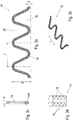
- FIG. 3a-3d is in four different representations, a first embodiment of a support 15 for use with a sliding sash, for example, the sliding sash 10 according to Fig. 2 represented.
- a portion of the overlay 15 is in Fig. 3a in a supervision and in Fig. 3b reproduced in an isometric view.
- Fig. 3c shows a sectional view through the support 15 in a direction transverse to the longitudinal extent of the support 15th Fig. 3d gives the circled area of the Fig. 3c increases again.
- the support 15 consists of a band-shaped material having a web width b 'and a thickness d.
- This strip-shaped material runs undulating along a longitudinal direction l, which is also the direction of the longitudinal extension of the end face of the surface element 11 and the longitudinal direction in which the edge profile 12 extends.
- the wave structure has a repeat length l '. Due to the wave structure, the support 15 assumes a total width b, which is many times greater than the web width b 'of the material of the support 15.
- the support 15 can be made of plastic in an extrusion process in the manner of a continuous material and a subsequent punching process or in an injection molding process as a rod material. With sufficient length of the rods, the support 15 can extend in one piece and continuously over the substantially entire length of the edge profile 12. Alternatively, two or more pads 15 can be inserted one behind the other in an edge profile 12, if the edge profile 12 is longer than the individual support 15.
- a plastic material for example, polyethylene (PE), polyamide (PA) or polypropylene (PP) are suitable.
- the width b is chosen so that the edge profile 12 is also substantially filled in its width.
- the wave structure allows by upsetting or pulling apart in the longitudinal direction, a variation of the width b, whereby the illustrated support 15 can also be used for different widths of the edge profile.
- the support 15 can be inserted into the edge profile 12, wherein in addition an adhesive can be used for fixing. Also, an adhesive or a sealant can be used to fill remaining areas 30, which does not occupy the support 15, and thus to establish a secure connection between the edge profile 12 and the surface element 11.
- Adhesive is applied to the support 15 inserted into the edge profile 12, if necessary additionally the regions 30 being filled with adhesive or sealing compound. A thus prepared edge profile 12 is then placed on the edge of the surface element 11 and glued to the surface element eleventh
- the support 15 provides in the edge profile 12 a uniform support for the surface element 11 at a plurality of support points.
- the support is not over the entire surface, which increases the pressure on the support 15 at the support points. Even when using a relatively hard plastic for the surface element 11, this leads to a sufficient deformability at the support points, so that a thickness compensation to compensate for unevenness of the surface element 11 on the front side, for example, protruding glass is guaranteed.
- the number of contact points per unit length can be influenced by varying the repetition length l 'of the wave structure.
- the size of the support surface in a support point can be influenced by the web width b '.
- the deformability of the support 15 is controlled by the fact that a structured surface 16 is provided at the top and bottom of the support 15.
- the structured surface 16 is particularly good in the enlargement of the cross section in the Fig. 3d to recognize.
- a serrated structure is introduced.
- FIGS. 4a-4d is the same as in the Figures 3a-3d a further embodiment of a support 15 shown for use in a sliding sash.
- the support 15 is constructed of two corrugated webs extending in opposite phase or mirror image to each other.
- the load-bearing capacity and the flexibility of the support 15 can also be adjusted here by varying the repeat length l' of the wave structure. To a lesser extent, but not as pronounced as in the embodiment of Figures 3a-3d , is possible by stretching and compressing in the longitudinal direction l a variation of the repeat length l 'and the width b.
- the support 15 is formed in a ladder-like structure and has two longitudinally extending side webs 17 and a plurality of transverse webs 18.
- the load bearing capacity can be varied by varying the repetition length l 'of the structure, which here corresponds to the distance between two adjacent transverse webs 18.
- the top and bottom of the support 15 are provided with a structured, in turn serrated surface 16. With regard to the materials and the possible different configurations of the structured surface 16 applies to the examples of FIGS. 4a-4d and 5a-5d that in connection with the embodiment of the Figures 3a-3d said.
Landscapes
- Engineering & Computer Science (AREA)
- Civil Engineering (AREA)
- Structural Engineering (AREA)
- Specific Sealing Or Ventilating Devices For Doors And Windows (AREA)
Abstract
Description
- Die Erfindung betrifft einen Schiebeflügel einer Schiebetüranordnung, bei der Tragerollen für den Schiebeflügel ortsfest sind. Der Schiebeflügel weist ein Flächenelement auf, bei dem auf zumindest einer den Tragerollen zugewandten Stirnseite ein Randprofil aufgesetzt ist. Die Erfindung betrifft weiter eine Schiebetüranordnung mit einem Bodenprofil mit ortsfesten Tragrollen und mindestens einem Schiebeflügel.
- Gegenüber Schiebetüranordnungen, bei dem der Schiebeflügel einen tragenden Rahmen aufweist, in dem Laufrollen angeordnet sind, erlaubt die eingangs genannte Schiebetüranordnung bei gegebener Größe einer Gebäudeöffnung die Verwendung eines größeren Flächenelements, beispielsweise einer größeren Isolierglasscheibe. Zudem wird eine optisch elegantere Erscheinung des Schiebeflügels ermöglicht, da diese verglichen mit einem tragenden Rahmen nur ein sehr schmales Randprofil aufweist. Die Tragerollen sind bevorzugt in einem Bodenprofil gelagert, das in einem Boden eines Gebäudes versenkt und damit bodenbündig montiert ist.
- Eine derartige Schiebetüranordnung ist beispielsweise aus der Druckschrift
WO 2010/024703 A1 bekannt. Bei dieser Anordnung wird ein u-förmiges Randprofil auf eine Isolierglasscheibe als Flächenelement aufgesetzt, wobei das Randprofil an seiner dem Flächenelement abweisenden Seite Laufbahnen aufweist, mit denen es auf den Tragerollen aufliegt. - Bei selbsttragenden Rahmen sind die Flächenelemente üblicherweise nur an wenigen ausgewählten Punkten durch sogenannte Glasklötze im Rahmen unterstützt. Bei den vorliegenden Schiebeflügeln sind die Randprofile jedoch nicht alleine in der Lage, die punktuell an den Tragerollen wirkenden Gewichtskräfte des Flächenelements seitlich entlang der Stirnseite des Flächenelements zu verteilen. Stattdessen wird das Flächenelement selbst zur Aufnahme und Verteilung der punktuellen Kräfte eingesetzt. Zu diesem Zweck liegt das Flächenelement unmittelbar an Randprofil auf und ist gegebenenfalls mit diesem verklebt.
- Bei großen Isolierglasscheiben und insbesondere bei großen Dreifach-Isolierglasscheiben ist - wenn überhaupt - nur mit großem Aufwand möglich, eine Seitenkante bereitzustellen, bei der die Schnittkanten aller Glasscheiben der Isolierglasscheibe weitestgehend in einer Ebene liegen. Eine abschnittsweise oder über die gesamte Länge der Stirnseite hervorstehende Glasscheibe führt jedoch zu einer ungleichen Kräfteverteilung auf die Glasscheiben, was zu Absplitterungen oder zu einem Glasbruch führen kann. Ein Höhenausgleich der einzelnen Scheiben durch eine eingebrachte Kleberschicht ist dabei nur bei kleineren Höhenabweichungen möglich. Grund hierfür ist, dass die Gleichmä-ßigkeit einer dickeren Kleberlage zwischen Isolierglasscheibe und Randprofil nur schlecht kontrollierbar ist, sodass eine durchgängige und gleichmäßige Unterstützung über die gesamte Länge der Stirnseite des Flächenelements kaum gewährleistet ist.
- Es ist daher eine Aufgabe der vorliegenden Erfindung, einen Schiebeflügel sowie eine Schiebetüranordnung der eingangs genannten Art zu schaffen, bei denen auch große Flächenelemente, insbesondere Dreifach-Isolierglasscheiben, in einer Schiebetüranordnung mit ortsfesten Tragerollen verwendet werden können. Insbesondere soll eine gleichmäßige Kräfteübertragung zwischen dem Randprofil und dem Flächenelement bei gutem Toleranzausgleich erzielt werden.
- Diese Aufgabe wird durch einen Schiebeflügel einer Schiebetüranordnung sowie eine Schiebetüranordnung mit den Merkmalen des jeweiligen unabhängigen Anspruchs gelöst. Vorteilhafte Ausgestaltungen und Weiterbildungen sind Gegenstand der abhängigen Ansprüche.
- Ein erfindungsgemäßer Schiebeflügel der eingangs genannten Art zeichnet sich dadurch aus, dass zwischen der Stirnseite des Flächenelements und dem Randprofil eine sich in Längsrichtung des Randprofils erstreckende Auflageleiste aus Kunststoff eingesetzt ist.
- Das Randprofil ist bevorzugt ein Metallprofil oder ein Kunststoffprofil aus einem harten Kunststoff wie PVC (Polyvinylchlorid), ggf. mit Glasfaserverstärkung. Demgegenüber ist die Auflageleiste weicher und weist bevorzugt eine Shor-Härte A von 60 bis 80 auf. Sie kann leicht eingedrückt werden und somit einen Dickenausgleich herstellen. Gleichzeitig weist sie eine gleichmäßige Dicke auf, die zu einem guten und gleichmäßigen Sitz des Randprofils auf dem Flächenelement führt.
- In einer bevorzugten Ausgestaltung des Schiebeflügels erstreckt sich die Auflageleiste ein- oder mehrteilig im Wesentlichen über die gesamte Länge der Stirnseite des Flächenelements. Bevorzugt unterstützt die Auflage die Stirnseite des Flächenelements dabei zudem über seine gesamte Breite. So kann die Gewichtskraft des gesamten Flächenelements bestmöglich gleichmäßig auf das Randprofil übertragen werden.
- In einer weiteren bevorzugten Ausgestaltung des Schiebeflügels unterstützt die Auflage die Stirnseite des Flächenelements jedoch nicht vollflächig, sondern in einer Mehrzahl von möglichst gleichmäßig verteilten Auflagepunkten. Durch die nicht vollflächige Ausgestaltung wird der Druck auf die Auflage an den Auflagepunkten erhöht. Auch bei Verwendung eines relativ harten Kunststoffs für die Auflage führt dieses zu einer ausreichenden Verformbarkeit an den Auflagestellen, sodass ein Dickenausgleich zum Ausgleich von Unebenheiten des Flächenelements an der Stirnseite gewährleistet ist.
- Dazu kann der die Auflage beispielsweise mindestens einen in Wellenform verlaufenden Steg umfassen, wobei der Steg beispielsweise einen rechteckigen Querschnitt aufweisen kann. Alternativ kann die Auflage leiterförmig ausgebildet sein mit mindestens einem in Längsrichtung verlaufenden Längssteg und einer Mehrzahl von Querstegen. Durch die genannten Strukturen verbleiben Freiräume, in denen das Flächenelement nicht unterstützt wird. In diesen Freiräumen kann ein Klebstoff oder eine Dichtmasse eingebracht werden, durch den bzw. die eine sichere Verbindung des Flächenelements mit dem Randprofil gewährleistet wird.
- In einer weiteren bevorzugten Ausgestaltung des Schiebeflügels ist die Auflage durch Stauchen oder Auseinanderziehen in Längsrichtung in ihrer Breite variierbar. Dieses kann beispielsweise gut bei einer Auflage umgesetzt sein, die einen in Wellenform verlaufenden Steg umfasst. Die Auflage kann so in ihrer Breite an verschieden dicke Flächenelemente angepasst werden und braucht nicht in allen benötigten Breiten separat gefertigt und vorgehalten werden. In Unterschied zur Breite kann die Länge leicht angepasst werden.
- In einer weiteren bevorzugten Ausgestaltung des Schiebeflügels weist die Auflage an ihrer Ober- und/oder Unterseite eine strukturierte Oberfläche auf. Die strukturierte Oberfläche kann bevorzugt mit einer Zackenstruktur versehen sein. Durch die Strukturierung der Oberfläche lässt sich die Verformbarkeit der Auflage zusätzlich kontrollieren. Durch unterschiedliche Formgebung beispielsweise der Zacke (spitze bzw. weniger spitze Dreiecksstrukturen bzw. tiefe oder weniger tiefe Strukturen) kann im Herstellungsprozess gezielt eine gewünschte Verformbarkeit der Auflage bei gegebenem Kunststoffmaterial eingestellt werden.
- Eine erfindungsgemäße Schiebetüranordnung weist mindestens ein Bodenprofil auf, in dem Tragerollen ortsfest angeordnet sind, und mindestens einen auf den Tragerollen verschiebbar geführten derartigen Schiebeflügel. Es ergeben sich die im Zusammenhang mit dem Schiebeflügel genannten Vorteile.
- Die Erfindung wird nachfolgend anhand von Ausführungsbeispielen mithilfe von Figuren näher erläutert. Die Figuren zeigen:
- Figur 1
- eine schematische teilgeschnittene Seitenansicht einer Schiebetüranordnung;
- Figur 2
- eine schematische Zeichnung eines Teils einer Schiebetüranordnung;
- Figuren 3a-d
- ein erstes Ausführungsbeispiel einer Auflage für ein Flächenelement in einem Schiebeflügel in verschiedenen Ansichten;
- Figuren 4a-d
- ein zweites Ausführungsbeispiel einer Auflage für ein Flächenelement in einem Schiebeflügel in verschiedenen Ansichten;
- Figuren 5a-d
- ein drittes Ausführungsbeispiel einer Auflage für ein Flächenelement in einem Schiebeflügel in verschiedenen Ansichten.
-
Fig. 1 zeigt in einer schematischen teilgeschnittenen Seitenansicht eine Schiebetüranordnung, in der ein anmeldungsgemäßer Schiebeflügel verwendet ist. - In einem Boden 1 ist in einer Vertiefung 2 ein Bodenprofil 20 eingelassen, in dem in regelmäßigen Abständen Tragerollen 24 ortsfest drehbar gelagert sind.
- Auf die Tragrollen 24 sind zwei Schiebeflügel 10 aufgesetzt, die jeweils ein Flächenelement 11, insbesondere eine Isolierglasscheibe, aufweisen. Der Übersichtlichkeit halber sind in der
Fig. 1 die Schiebeflügel 10 nach oben versetzt dargestellt. - Die Flächenelemente 11 sind an ihrer unteren, den Tragrollen 24 zugewandten Stirnseite von jeweils einem Randprofil 12 eingefasst. An den jeweiligen drei weiteren Stirnseiten sind weitere Randprofile 13 angeordnet. Bezüglich ihres Querschnitts können die weiteren Randprofile 13 gleich oder ähnlich dem unten angeordneten Randprofil 12 ausgebildet sein. Ein Randprofil 12 und jeweils drei weitere Randprofile 13 umfassen jedes Flächenelement 11 wie ein Rahmen, der jedoch nicht selbsttragend ist und nur in Verbindung mit dem Flächenelement 11 die notwendige Stabilität aufweist.
- Die Schiebeflügel 10 sind mit ihrem unteren Randprofil 12 auf die Tragrollen 24 aufgesetzt. Im oberen Bereich der Schiebeflügel 10 sind Führungen vorgesehen, die ein Verkippen der Schiebeflügel 10 aus ihrer senkrechten Lage verhindern. Die Schiebeflügel 10 können unmittelbar mit dem unteren Randprofil 12 auf den Tragrollen 24 laufen. Alternativ kann ein separates Laufprofil, das die eigentliche Lauffläche bereitstellt, an dem Randprofil 12 befestigt sein.
- Eine anmeldungsgemäße Schiebetüranordnung kann einen oder mehrere derartige Schiebeflügel 10 aufweisen. Wenn mehrere gegeneinander verschiebbare Schiebeflügel 10 vorgesehen sind, sind diese in verschiedenen Ebenen hintereinander angeordnet, sodass sie einander vorbeibewegt werden können. Entsprechend sind Tragrollen 24 ebenfalls in verschiedenen, in der Bodenebene nebeneinander liegenden Linien hintereinander angeordnet.
-
Fig. 2 zeigt einen Schnitt durch ein Bodenprofil 20 sowie einen Ausschnitt eines aufgesetzten Schiebeflügels 10 in einem weiteren Ausführungsbeispiel einer Schiebetüranordnung. - Im Unterschied zum Beispiel der
Fig. 1 ist vorliegend zumindest im Bereich der dargestellten Schnittebene nur ein bewegbarer Schiebeflügel 10 vorgesehen. Zur Aufnahme eines weiteren Schiebeflügels in einem anderen Abschnitt der Schiebetüranordnung oder eines fest stehenden Flügels sind dennoch zwei nebeneinander liegende identische und spiegelbildlich angeordnete Bodenprofile 20 in den hier nicht dargestellten Boden eingelassen. - Die beiden Bodenprofile 20 sind über Isolierstege 21 miteinander gekoppelt. Sie sind durch in dieser Figur ebenfalls nicht sichtbare Verankerungen in einer Vertiefung des Bodens montiert.
- Das in der
Fig. 2 auf der rechten Seite angeordnete Bodenprofil 20 weist ein eingesetztes Tragrollenprofil 22 auf, in dem in regelmäßigen Abständen die Tragrollen 24 mittels Bolzen 23 drehbar gelagert sind. Im oberen Bereich des Bodenprofils 20 bzw. des oberen der Isolierstege 21 sind längsverlaufende Bürsten 25 in nutenförmige Aufnahmen eingesetzt, die an dem eingesetzten Schiebeflügel 10 entlang streichen und ein Eindringen von Staub in den unteren Bereich des Schiebeflügels 10 verringern. - Das in der
Fig. 2 links dargestellte Bodenprofil 20 ist ohne das Tragrollenprofil 22 ausgestattet. Stattdessen ist eine zum Boden ebene Abdeckung 26 in Halter eingesetzt, die ihrerseits in den Nuten für die Bürsten 25 in das Bodenprofil 20 bzw. den Isoliersteg 21 eingesetzt sind. - Der Schiebeflügel 10 umfasst ein Flächenelement 11, das vorliegend als dreifach-Isolierglasscheibe ausgebildet ist. Das Flächenelement 11 ist an seiner unteren Stirnseite von dem Randprofil 12 und an seinen anderen drei Stirnseiten von weiteren Randprofilen 13 eingefasst. Die weiteren Randprofile 13 werden wahlweise mit einem üblichen Kleber oder einer Dichtmasse an dem Flächenelement 11 gehalten.
- Das Randprofil 12 ist im Wesentlichen u-förmig ausgebildet, wobei das Flächenelement 11 mit seiner unteren Stirnseite auf einer Auflage 15 aufliegt, die in das u-förmige Randprofil 12 eingelegt ist. Details zur Ausgestaltung der Auflage 15 werden im Zusammenhang mit den nachfolgenden Figuren näher beschrieben.
- Zwischen den seitlich nach oben ragenden Schenkel des u-förmigen Randprofils 12 und dem Flächenelement 11 ist zu jeder Seite eine Dichtung 15 eingesetzt.
- Bei dem dargestellten Ausführungsbeispiel rollen die Tragrollen 24 nicht unmittelbar auf den Randprofil 12 ab, sondern auf einem Laufprofil 12', das zentral unter dem Randprofil 12 angeordnet und mit diesem verschraubt ist. Diese Anordnung bietet den Vorteil, das Laufprofil 12' aus einem anderen Material fertigen zu können als das Randprofil 12. Beispielsweise kann eine andere Härte für das Laufprofil 12' gewählt werden als für das Randprofil 12, wodurch sich Abrolleigenschaften und auch Abrollgeräusche beeinflussen lassen. Im dargestellten Ausführungsbeispiel sind die Tragrollen 24 mit einer v-förmig eingekerbten Lauffläche versehen und das Laufprofil 12' weist entsprechend ein nach unten weisendes v-förmiges Laufprofil auf. Auf diese Weise wird mit nur einer Reihe von Tragrollen 24 eine Seitenführung für den Schiebeflügel 10 erzielt.
- In den
Figuren 3a-3d ist in vier verschiedenen Darstellungen ein erstes Ausführungsbeispiel einer Auflage 15 zur Verwendung mit einem Schiebeflügel, beispielsweise dem Schiebeflügel 10 gemäßFig. 2 , dargestellt. Ein Abschnitt der Auflage 15 ist inFig. 3a in einer Aufsicht und inFig. 3b in einer isometrischen Darstellung wiedergegeben.Fig. 3c zeigt eine Schnittansicht durch die Auflage 15 in einer Richtung quer zur Längserstreckung der Auflage 15.Fig. 3d gibt den eingekreisten Bereich derFig. 3c vergrößert wieder. - Im dargestellten Ausführungsbeispiel besteht die Auflage 15 aus einem bandförmigen Material, das eine Stegbreite b' und eine Dicke d aufweist. Dieses bandförmige Material verläuft wellenförmig entlang einer Längsrichtung l, die auch die Richtung der Längserstreckung der Stirnseite des Flächenelements 11 ist bzw. die Längsrichtung, in die sich das Randprofil 12 erstreckt, darstellt. Die Wellenstruktur weist eine Wiederhollänge l' auf. Durch die Wellenstruktur nimmt die Auflage 15 eine Gesamtbreite b ein, die um ein Vielfaches größer als die Stegbreite b' des Materials der Auflage 15 beträgt.
- Die Auflage 15 kann aus Kunststoff in einem Extrodierprozess in Art eines Endlosmaterials und einem nachfolgenden Stanzprozess oder in einem Spritzgussprozess als Stangenmaterial hergestellt werden. Bei ausreichender Länge der Stangen kann die Auflage 15 einstückig und durchgängig über die im Wesentlichen gesamte Länge des Randprofils 12 verlaufen. Alternativ können auch zwei oder mehr Auflagen 15 hintereinander in eine Randprofil 12 eingelegt werden, falls das Randprofil 12 länger als die einzelne Auflage 15 ist. Als Kunststoffmaterial sind beispielsweise Polyethylen (PE), Polyamid (PA) oder Polypropylen (PP) geeignet.
- Die Breite b ist so gewählt, dass das Randprofil 12 auch in seiner Breite im Wesentlichen ausgefüllt ist. Die Wellenstruktur ermöglicht dabei durch ein Stauchen oder Auseinanderziehen in Längsrichtung eine Variation der Breite b, wodurch die dargestellte Auflage 15 auch für verschiedene Breiten des Randprofils eingesetzt werden kann.
- Die Auflage 15 kann in das Randprofil 12 eingelegt werden, wobei zusätzlich ein Klebstoff zum Fixieren verwendet werden kann. Auch kann eine Klebstoff oder eine Dichtmasse eingesetzt werden, um verbleibenden Bereiche 30, die die Auflage 15 nicht einnimmt, auszufüllen und so eine sichere Verbindung zwischen dem Randprofil 12 und dem Flächenelement 11 herzustellen.
- Auf die in das Randprofil 12 eingelegte Auflage 15 wird Klebstoff aufgetragen, wobei ggf. zusätzlich die Bereiche 30 mit Klebstoff oder Dichtmasse ausgefüllt sind. Ein so vorbereitetes Randprofil 12 wird anschließend auf den Rand des Flächenelements 11 aufgesetzt und verklebt mit dem Flächenelement 11.
- Die Auflage 15 bietet im Randprofil 12 eine gleichmäßige Unterstützung für das Flächenelement 11 an einer Vielzahl von Auflagestellen. Die Unterstützung ist jedoch nicht vollflächig, was den Druck auf die Auflage 15 an den Auflagepunkten erhöht. Auch bei Verwendung eines relativ harten Kunststoffs für das Flächenelement 11 führt dieses zu einer ausreichenden Verformbarkeit an den Auflagestellen, sodass ein Dickenausgleich zum Ausgleich von Unebenheiten des Flächenelements 11 an der Stirnseite, beispielsweise hervorstehenden Glasscheiben, gewährleistet ist.
- Die Anzahl der Auflagepunkte pro Längeneinheit kann durch Variation der Wiederhollänge l' der Wellenstruktur beeinflusst werden. Die Größe der Auflagefläche in einem Auflagepunkt ist durch die Stegbreite b' beeinflussbar.
- Zusätzlich ist die Verformbarkeit der Auflage 15 dadurch kontrolliert, dass eine strukturierte Oberfläche 16 an Ober- und Unterseite der Auflage 15 vorgesehen ist. Die strukturierte Oberfläche 16 ist insbesondere gut in der Vergrößerung des Querschnitts in der
Fig. 3d zu erkennen. Vorliegend ist eine Zackenstruktur eingebracht. Durch unterschiedliche Formgebung der Zacken (spitze bzw. weniger spitze Dreiecksstrukturen bzw. tiefe oder weniger tiefe Strukturen) kann im Herstellungsprozess gezielt eine gewünschte Verformbarkeit der Auflage 15 bei gegebenem Kunststoffmaterial eingestellt werden. - In den
Figuren 4a-4d ist in gleicher Weise wie in denFiguren 3a-3d eine weitere Ausgestaltung einer Auflage 15 zur Verwendung in einem Schiebeflügel dargestellt. Bei diesem Ausführungsbeispiel ist die Auflage 15 aus zwei wellenförmig verlaufenden Stegen aufgebaut, die gegenphasig bzw. spiegelbildlich zueinander verlaufen. - Wie beim ersten Ausführungsbeispiel der
Figuren 3a-3d sind wieder die Ober- und die Unterseite der Auflage 15 mit einer strukturierten (hier gezackten) Oberfläche 16 versehen. Neben der Breite b' und der Dicke d der einzelnen wellenförmig verlaufenden Stege kann die Tragfähigkeit und die Nachgiebigkeit der Auflage 15 auch hier durch Variation der Wiederhollänge l' der Wellenstruktur eingestellt werden. In geringen Maße, allerdings nicht so ausgeprägt wie beim Ausführungsbeispiel derFiguren 3a-3d , ist durch Strecken und Stauchen in Längsrichtung l eine Variation der Wiederhollänge l' und der Breite b möglich. - Die
Figuren 5a-5d zeigen schließlich ein weiteres Ausführungsbeispiel einer für Schiebeflügel 10 geeigneten Auflage 15. Bei diesem Ausführungsbeispiel ist die Auflage 15 in einer leiterartigen Struktur ausgebildet und weist zwei in Längsrichtung verlaufende Seitenstege 17 und eine Vielzahl von Querstegen 18 auf. Auch bei dieser Ausgestaltung kann die Tragfähigkeit durch Variation der Wiederhollänge l' der Struktur, die hier dem Abstand zweier benachbarter Querstege 18 entspricht, variiert werden. Wie bei den zuvor dargestellten Beispielen sind Ober- und Unterseite der Auflage 15 mit einer strukturierten, wiederum gezackten Oberfläche 16 versehen. Bezüglich der Materialien und der möglichen unterschiedlichen Ausgestaltungen der strukturierten Oberfläche 16 gilt für die Beispiele derFiguren 4a-4d und5a-5d das im Zusammenhang mit dem Ausführungsbeispiel derFiguren 3a-3d gesagte. -
- 1
- Boden
- 2
- Vertiefung
- 10
- Schiebeflügel
- 11
- Flächenelement
- 12
- Randprofil
- 13
- weiteres Randprofil
- 14
- Dichtung
- 15
- Auflage
- 16
- strukturierte (gezackte) Oberfläche
- 17
- Seitensteg
- 18
- Quersteg
- 20
- Bodenprofil
- 21
- Isoliersteg
- 22
- Tragrollenprofil
- 23
- Bolzen
- 24
- Tragrolle
- 25
- Bürste
- 26
- Abdeckung
- 30
- Bereich für Klebstoff und/oder Dichtmasse
Claims (15)
- Schiebeflügel (10) einer Schiebetüranordnung, bei der Tragerollen (24) für den Schiebeflügel (10) ortsfest sind, aufweisend ein Flächenelement (11), auf das auf zumindest eine den Tragerollen (24) zugewandte Stirnseite ein Randprofil (12) aufgesetzt ist, dadurch gekennzeichnet, dass zwischen der Stirnseite des Flächenelements (11) und dem Randprofil (12) eine sich in Längsrichtung des Randprofils (12) erstreckende Auflageleiste (15) aus Kunststoff eingesetzt ist.
- Schiebeflügel (10) nach Anspruch 1, bei dem sich die Auflageleiste (15) ein- oder mehrteilig im Wesentlichen über die gesamte Länge der Stirnseite des Flächenelements (11) erstreckt.
- Schiebeflügel (10) nach Anspruch 1 oder 2, bei dem die Auflage (15) die Stirnseite des Flächenelements (11) über seine gesamte Breite unterstützt.
- Schiebeflügel (10) nach einem der Ansprüche 1 bis 3, bei dem die Auflage (15) die Stirnseite des Flächenelements (11) nicht vollflächig unterstützt.
- Schiebeflügel (10) nach Anspruch 4, bei dem in Bereichen (30), in denen die Auflage (15) die Stirnseite des Flächenelements (11) nicht vollflächig unterstützt, ein Klebstoff und/oder eine Dichtmasse angeordnet ist.
- Schiebeflügel (10) nach einem der Ansprüche 1 bis 5, bei dem die Auflage (15) mindestens einen in Wellenform verlaufenden Steg umfasst.
- Schiebeflügel (10) nach Anspruch 6, bei dem der Steg einen rechteckigen Querschnitt aufweist.
- Schiebeflügel (10) nach einem der Ansprüche 1 bis 7, bei dem die Auflage (15) durch Stauchen oder Auseinanderziehen in Längsrichtung in ihrer Breite variierbar ist.
- Schiebeflügel (10) nach einem der Ansprüche 1 bis 8, bei dem die Auflage (15) leiterförmig ausgebildet ist mit mindestens einem in Längsrichtung verlaufenden Längssteg (17) und einer Mehrzahl von Querstegen (18) umfasst.
- Schiebeflügel (10) nach einem der Ansprüche 1 bis 9, bei dem die Auflage (15) an ihrer Ober- und/oder Unterseite eine strukturierte Oberfläche (16) aufweist.
- Schiebeflügel (10) nach Anspruch 10, bei dem die strukturierte Oberfläche (16) mit einer Zackenstruktur versehen ist.
- Schiebeflügel (10) nach einem der Ansprüche 1 bis 11, bei dem die Auflage (15) aus Polyethylen, Polyamid oder Polypropylen gefertigt ist.
- Schiebeflügel (10) nach einem der Ansprüche 1 bis 12, bei dem die Auflage (15) eine Shore-Härte A von 60 bis 80 aufweist.
- Schiebeflügel (10) nach einem der Ansprüche 1 bis 13, bei dem das Randprofil (12) und/oder weitere Randprofile (13), die an anderen Stirnseiten des Flächenelements (11) als das Randprofil (12) angeordnet sind, durch einen Klebstoff und/oder eine Dichtmasse mit dem Flächenelement (11) verbunden sind.
- Schiebetüranordnung mit mindestens einem Bodenprofil (20), in dem Tragerollen (24) ortsfest angeordnet sind, und mindestens einem auf den Tragerollen (24) verschiebbar geführten Schiebeflügel (10) gemäß einem der Ansprüche 1 bis 14.
Applications Claiming Priority (1)
| Application Number | Priority Date | Filing Date | Title |
|---|---|---|---|
| DE102016105124.1A DE102016105124A1 (de) | 2016-03-18 | 2016-03-18 | Schiebeflügel für eine Schiebetüranordnung |
Publications (2)
| Publication Number | Publication Date |
|---|---|
| EP3219895A1 true EP3219895A1 (de) | 2017-09-20 |
| EP3219895B1 EP3219895B1 (de) | 2024-01-10 |
Family
ID=58360917
Family Applications (1)
| Application Number | Title | Priority Date | Filing Date |
|---|---|---|---|
| EP17161656.8A Active EP3219895B1 (de) | 2016-03-18 | 2017-03-17 | Schiebetüranordnung und schiebeflügel einer schiebetüranordnung |
Country Status (5)
| Country | Link |
|---|---|
| EP (1) | EP3219895B1 (de) |
| DE (1) | DE102016105124A1 (de) |
| DK (1) | DK3219895T3 (de) |
| ES (1) | ES2974038T3 (de) |
| PL (1) | PL3219895T3 (de) |
Cited By (2)
| Publication number | Priority date | Publication date | Assignee | Title |
|---|---|---|---|---|
| EP3859117A1 (de) * | 2020-01-29 | 2021-08-04 | Christian Michels | Schiebefenstervorrichtung |
| WO2022268412A1 (en) * | 2021-09-02 | 2022-12-29 | Exlabesa Building Systems S.A.U. | Bearing system for a slide |
Citations (8)
| Publication number | Priority date | Publication date | Assignee | Title |
|---|---|---|---|---|
| DE9217883U1 (de) * | 1992-12-31 | 1994-05-05 | Niemann, Hans Dieter, 50169 Kerpen | Klotzteil zum Festsetzen von Glasscheiben o.dgl. in Nuten von Tür- oder Fensterrahmen |
| WO1998041724A1 (en) * | 1997-03-20 | 1998-09-24 | Lars Eriksson | Spacer having friction means |
| DE19939868A1 (de) * | 1999-08-23 | 2001-03-29 | Hans Dieter Niemann | Klotzteil und Werkzeug zu dessen Herstellung |
| EP1318264A2 (de) * | 2001-12-06 | 2003-06-11 | Hans Dieter Niemann | Abstützteil einer Verglasung |
| WO2010024703A1 (en) | 2008-08-29 | 2010-03-04 | Unlimited Perspective Sa | Frame for sliding doors or windows |
| EP2251519A1 (de) * | 2009-05-11 | 2010-11-17 | Hawa Ag | Verbindungsvorrichtung für ein Trennelement |
| EP2463470A1 (de) * | 2010-12-08 | 2012-06-13 | Orchidées Constructions S.A. | Rahmen für Wände |
| CN103850588A (zh) * | 2012-12-03 | 2014-06-11 | 北新集团建材股份有限公司 | 一种推拉门窗及其制作方法 |
Family Cites Families (2)
| Publication number | Priority date | Publication date | Assignee | Title |
|---|---|---|---|---|
| FR2492879A1 (fr) * | 1980-02-01 | 1982-04-30 | Superseal Corp | Chassis vitre isolant a double vitrage etanche, a monter mobile ou fixe dans une huisserie de fenetre ou de porte |
| JP5658813B1 (ja) * | 2013-11-25 | 2015-01-28 | 株式会社デバイス | ダブルガラススキン用のインナーガラススキン構造 |
-
2016
- 2016-03-18 DE DE102016105124.1A patent/DE102016105124A1/de not_active Withdrawn
-
2017
- 2017-03-17 PL PL17161656.8T patent/PL3219895T3/pl unknown
- 2017-03-17 ES ES17161656T patent/ES2974038T3/es active Active
- 2017-03-17 EP EP17161656.8A patent/EP3219895B1/de active Active
- 2017-03-17 DK DK17161656.8T patent/DK3219895T3/da active
Patent Citations (8)
| Publication number | Priority date | Publication date | Assignee | Title |
|---|---|---|---|---|
| DE9217883U1 (de) * | 1992-12-31 | 1994-05-05 | Niemann, Hans Dieter, 50169 Kerpen | Klotzteil zum Festsetzen von Glasscheiben o.dgl. in Nuten von Tür- oder Fensterrahmen |
| WO1998041724A1 (en) * | 1997-03-20 | 1998-09-24 | Lars Eriksson | Spacer having friction means |
| DE19939868A1 (de) * | 1999-08-23 | 2001-03-29 | Hans Dieter Niemann | Klotzteil und Werkzeug zu dessen Herstellung |
| EP1318264A2 (de) * | 2001-12-06 | 2003-06-11 | Hans Dieter Niemann | Abstützteil einer Verglasung |
| WO2010024703A1 (en) | 2008-08-29 | 2010-03-04 | Unlimited Perspective Sa | Frame for sliding doors or windows |
| EP2251519A1 (de) * | 2009-05-11 | 2010-11-17 | Hawa Ag | Verbindungsvorrichtung für ein Trennelement |
| EP2463470A1 (de) * | 2010-12-08 | 2012-06-13 | Orchidées Constructions S.A. | Rahmen für Wände |
| CN103850588A (zh) * | 2012-12-03 | 2014-06-11 | 北新集团建材股份有限公司 | 一种推拉门窗及其制作方法 |
Cited By (3)
| Publication number | Priority date | Publication date | Assignee | Title |
|---|---|---|---|---|
| EP3859117A1 (de) * | 2020-01-29 | 2021-08-04 | Christian Michels | Schiebefenstervorrichtung |
| WO2022268412A1 (en) * | 2021-09-02 | 2022-12-29 | Exlabesa Building Systems S.A.U. | Bearing system for a slide |
| US12146355B2 (en) | 2021-09-02 | 2024-11-19 | Exlabesa Building Systems S.A.U. | Bearing system for a slide |
Also Published As
| Publication number | Publication date |
|---|---|
| PL3219895T3 (pl) | 2024-05-06 |
| EP3219895B1 (de) | 2024-01-10 |
| DE102016105124A1 (de) | 2017-09-21 |
| ES2974038T3 (es) | 2024-06-25 |
| DK3219895T3 (da) | 2024-03-18 |
Similar Documents
| Publication | Publication Date | Title |
|---|---|---|
| AT401856B (de) | Schublade | |
| EP3380692B1 (de) | Schiebewandanordnung mit abdeckelement | |
| EP2813783A1 (de) | Ständer zum Abstützen von Solarpaneelen auf einem Flachdach | |
| DE202010008921U1 (de) | Mitteldichtung für hoch wärmegedämmte Fenster oder Türen | |
| DE202015106963U1 (de) | Glasgeländer-Halteanordnung und Keil-Profilteil zur Verwendung in einer solchen Anordnung | |
| DE102005004547A1 (de) | Verbundprofil mit einem Tragkörper aus Leichtmetallwerkstoff sowie einem Profilband und Verfahren zum Herstellen des Verbundprofils | |
| DE202012104033U1 (de) | Haltevorrichtung für eine Brüstungs- oder Geländerplatte sowie Geländer oder Brüstung mit Scheibe | |
| EP2317054A2 (de) | Schiebetür | |
| EP2546448B1 (de) | Vorrichtung zum Verschieben eines Schiebeelements | |
| EP1452657A2 (de) | Fassade mit Dämmblock | |
| DE102014103950A1 (de) | Isolierelement für Fassaden- oder Lichtdachkonstruktionen | |
| EP3219895B1 (de) | Schiebetüranordnung und schiebeflügel einer schiebetüranordnung | |
| EP2754842A1 (de) | Dichtungsprofil für ein Rahmenprofil und Rahmenprofil | |
| EP1290307B1 (de) | Bauelement und verwendung eines bauelements sowie verfahren zur herstellung eines bauelements | |
| AT391736B (de) | Anordnung zum abdichten einer verglasung im fluegel eines fensters, einer tuere oder dgl. aus holz | |
| DE19613044A1 (de) | Pfosten-Sprossen-Konstruktion | |
| EP3748115B1 (de) | Bodenschwelle für eine schiebetür | |
| DE102011113456A1 (de) | Wärmegedämmtes Verbundprofil | |
| DE8617287U1 (de) | Verglasungsklotz | |
| DE3049841C2 (de) | ||
| EP4012147B1 (de) | Glasfalzeinlage für ein fensterrahmenprofil und system und verfahren zur verglasung eines fensterrahmens | |
| EP3176340B1 (de) | Dichtung, sowie pfosten-riegel-anordnung | |
| DE29820399U1 (de) | Abstützelement einer Glasscheibe | |
| EP3045601B1 (de) | Pfosten-riegel-konstruktion | |
| EP2163720B1 (de) | Elastische Strangdichtung für Holzfenster, Holztüren oder dgl. |
Legal Events
| Date | Code | Title | Description |
|---|---|---|---|
| PUAI | Public reference made under article 153(3) epc to a published international application that has entered the european phase |
Free format text: ORIGINAL CODE: 0009012 |
|
| STAA | Information on the status of an ep patent application or granted ep patent |
Free format text: STATUS: THE APPLICATION HAS BEEN PUBLISHED |
|
| AK | Designated contracting states |
Kind code of ref document: A1 Designated state(s): AL AT BE BG CH CY CZ DE DK EE ES FI FR GB GR HR HU IE IS IT LI LT LU LV MC MK MT NL NO PL PT RO RS SE SI SK SM TR |
|
| AX | Request for extension of the european patent |
Extension state: BA ME |
|
| STAA | Information on the status of an ep patent application or granted ep patent |
Free format text: STATUS: REQUEST FOR EXAMINATION WAS MADE |
|
| 17P | Request for examination filed |
Effective date: 20180320 |
|
| RBV | Designated contracting states (corrected) |
Designated state(s): AL AT BE BG CH CY CZ DE DK EE ES FI FR GB GR HR HU IE IS IT LI LT LU LV MC MK MT NL NO PL PT RO RS SE SI SK SM TR |
|
| STAA | Information on the status of an ep patent application or granted ep patent |
Free format text: STATUS: EXAMINATION IS IN PROGRESS |
|
| 17Q | First examination report despatched |
Effective date: 20200722 |
|
| GRAP | Despatch of communication of intention to grant a patent |
Free format text: ORIGINAL CODE: EPIDOSNIGR1 |
|
| STAA | Information on the status of an ep patent application or granted ep patent |
Free format text: STATUS: GRANT OF PATENT IS INTENDED |
|
| INTG | Intention to grant announced |
Effective date: 20230823 |
|
| GRAS | Grant fee paid |
Free format text: ORIGINAL CODE: EPIDOSNIGR3 |
|
| P01 | Opt-out of the competence of the unified patent court (upc) registered |
Effective date: 20231031 |
|
| GRAA | (expected) grant |
Free format text: ORIGINAL CODE: 0009210 |
|
| STAA | Information on the status of an ep patent application or granted ep patent |
Free format text: STATUS: THE PATENT HAS BEEN GRANTED |
|
| AK | Designated contracting states |
Kind code of ref document: B1 Designated state(s): AL AT BE BG CH CY CZ DE DK EE ES FI FR GB GR HR HU IE IS IT LI LT LU LV MC MK MT NL NO PL PT RO RS SE SI SK SM TR |
|
| REG | Reference to a national code |
Ref country code: GB Ref legal event code: FG4D Free format text: NOT ENGLISH |
|
| REG | Reference to a national code |
Ref country code: CH Ref legal event code: EP |
|
| REG | Reference to a national code |
Ref country code: DE Ref legal event code: R096 Ref document number: 502017015742 Country of ref document: DE |
|
| REG | Reference to a national code |
Ref country code: IE Ref legal event code: FG4D Free format text: LANGUAGE OF EP DOCUMENT: GERMAN |
|
| REG | Reference to a national code |
Ref country code: DK Ref legal event code: T3 Effective date: 20240315 |
|
| REG | Reference to a national code |
Ref country code: SE Ref legal event code: TRGR |
|
| REG | Reference to a national code |
Ref country code: NL Ref legal event code: FP |
|
| REG | Reference to a national code |
Ref country code: LT Ref legal event code: MG9D |
|
| REG | Reference to a national code |
Ref country code: ES Ref legal event code: FG2A Ref document number: 2974038 Country of ref document: ES Kind code of ref document: T3 Effective date: 20240625 |
|
| PG25 | Lapsed in a contracting state [announced via postgrant information from national office to epo] |
Ref country code: IS Free format text: LAPSE BECAUSE OF FAILURE TO SUBMIT A TRANSLATION OF THE DESCRIPTION OR TO PAY THE FEE WITHIN THE PRESCRIBED TIME-LIMIT Effective date: 20240510 |
|
| PG25 | Lapsed in a contracting state [announced via postgrant information from national office to epo] |
Ref country code: LT Free format text: LAPSE BECAUSE OF FAILURE TO SUBMIT A TRANSLATION OF THE DESCRIPTION OR TO PAY THE FEE WITHIN THE PRESCRIBED TIME-LIMIT Effective date: 20240110 |
|
| PG25 | Lapsed in a contracting state [announced via postgrant information from national office to epo] |
Ref country code: GR Free format text: LAPSE BECAUSE OF FAILURE TO SUBMIT A TRANSLATION OF THE DESCRIPTION OR TO PAY THE FEE WITHIN THE PRESCRIBED TIME-LIMIT Effective date: 20240411 |
|
| PG25 | Lapsed in a contracting state [announced via postgrant information from national office to epo] |
Ref country code: HR Free format text: LAPSE BECAUSE OF FAILURE TO SUBMIT A TRANSLATION OF THE DESCRIPTION OR TO PAY THE FEE WITHIN THE PRESCRIBED TIME-LIMIT Effective date: 20240110 Ref country code: RS Free format text: LAPSE BECAUSE OF FAILURE TO SUBMIT A TRANSLATION OF THE DESCRIPTION OR TO PAY THE FEE WITHIN THE PRESCRIBED TIME-LIMIT Effective date: 20240410 |
|
| PG25 | Lapsed in a contracting state [announced via postgrant information from national office to epo] |
Ref country code: RS Free format text: LAPSE BECAUSE OF FAILURE TO SUBMIT A TRANSLATION OF THE DESCRIPTION OR TO PAY THE FEE WITHIN THE PRESCRIBED TIME-LIMIT Effective date: 20240410 Ref country code: LT Free format text: LAPSE BECAUSE OF FAILURE TO SUBMIT A TRANSLATION OF THE DESCRIPTION OR TO PAY THE FEE WITHIN THE PRESCRIBED TIME-LIMIT Effective date: 20240110 Ref country code: IS Free format text: LAPSE BECAUSE OF FAILURE TO SUBMIT A TRANSLATION OF THE DESCRIPTION OR TO PAY THE FEE WITHIN THE PRESCRIBED TIME-LIMIT Effective date: 20240510 Ref country code: HR Free format text: LAPSE BECAUSE OF FAILURE TO SUBMIT A TRANSLATION OF THE DESCRIPTION OR TO PAY THE FEE WITHIN THE PRESCRIBED TIME-LIMIT Effective date: 20240110 Ref country code: GR Free format text: LAPSE BECAUSE OF FAILURE TO SUBMIT A TRANSLATION OF THE DESCRIPTION OR TO PAY THE FEE WITHIN THE PRESCRIBED TIME-LIMIT Effective date: 20240411 Ref country code: BG Free format text: LAPSE BECAUSE OF FAILURE TO SUBMIT A TRANSLATION OF THE DESCRIPTION OR TO PAY THE FEE WITHIN THE PRESCRIBED TIME-LIMIT Effective date: 20240110 |
|
| PG25 | Lapsed in a contracting state [announced via postgrant information from national office to epo] |
Ref country code: PT Free format text: LAPSE BECAUSE OF FAILURE TO SUBMIT A TRANSLATION OF THE DESCRIPTION OR TO PAY THE FEE WITHIN THE PRESCRIBED TIME-LIMIT Effective date: 20240510 |
|
| PG25 | Lapsed in a contracting state [announced via postgrant information from national office to epo] |
Ref country code: PT Free format text: LAPSE BECAUSE OF FAILURE TO SUBMIT A TRANSLATION OF THE DESCRIPTION OR TO PAY THE FEE WITHIN THE PRESCRIBED TIME-LIMIT Effective date: 20240510 Ref country code: LV Free format text: LAPSE BECAUSE OF FAILURE TO SUBMIT A TRANSLATION OF THE DESCRIPTION OR TO PAY THE FEE WITHIN THE PRESCRIBED TIME-LIMIT Effective date: 20240110 |
|
| REG | Reference to a national code |
Ref country code: DE Ref legal event code: R097 Ref document number: 502017015742 Country of ref document: DE |
|
| PG25 | Lapsed in a contracting state [announced via postgrant information from national office to epo] |
Ref country code: SM Free format text: LAPSE BECAUSE OF FAILURE TO SUBMIT A TRANSLATION OF THE DESCRIPTION OR TO PAY THE FEE WITHIN THE PRESCRIBED TIME-LIMIT Effective date: 20240110 |
|
| PG25 | Lapsed in a contracting state [announced via postgrant information from national office to epo] |
Ref country code: CZ Free format text: LAPSE BECAUSE OF FAILURE TO SUBMIT A TRANSLATION OF THE DESCRIPTION OR TO PAY THE FEE WITHIN THE PRESCRIBED TIME-LIMIT Effective date: 20240110 Ref country code: EE Free format text: LAPSE BECAUSE OF FAILURE TO SUBMIT A TRANSLATION OF THE DESCRIPTION OR TO PAY THE FEE WITHIN THE PRESCRIBED TIME-LIMIT Effective date: 20240110 |
|
| PG25 | Lapsed in a contracting state [announced via postgrant information from national office to epo] |
Ref country code: SK Free format text: LAPSE BECAUSE OF FAILURE TO SUBMIT A TRANSLATION OF THE DESCRIPTION OR TO PAY THE FEE WITHIN THE PRESCRIBED TIME-LIMIT Effective date: 20240110 |
|
| PG25 | Lapsed in a contracting state [announced via postgrant information from national office to epo] |
Ref country code: SM Free format text: LAPSE BECAUSE OF FAILURE TO SUBMIT A TRANSLATION OF THE DESCRIPTION OR TO PAY THE FEE WITHIN THE PRESCRIBED TIME-LIMIT Effective date: 20240110 Ref country code: SK Free format text: LAPSE BECAUSE OF FAILURE TO SUBMIT A TRANSLATION OF THE DESCRIPTION OR TO PAY THE FEE WITHIN THE PRESCRIBED TIME-LIMIT Effective date: 20240110 Ref country code: RO Free format text: LAPSE BECAUSE OF FAILURE TO SUBMIT A TRANSLATION OF THE DESCRIPTION OR TO PAY THE FEE WITHIN THE PRESCRIBED TIME-LIMIT Effective date: 20240110 Ref country code: EE Free format text: LAPSE BECAUSE OF FAILURE TO SUBMIT A TRANSLATION OF THE DESCRIPTION OR TO PAY THE FEE WITHIN THE PRESCRIBED TIME-LIMIT Effective date: 20240110 Ref country code: CZ Free format text: LAPSE BECAUSE OF FAILURE TO SUBMIT A TRANSLATION OF THE DESCRIPTION OR TO PAY THE FEE WITHIN THE PRESCRIBED TIME-LIMIT Effective date: 20240110 |
|
| PLBE | No opposition filed within time limit |
Free format text: ORIGINAL CODE: 0009261 |
|
| STAA | Information on the status of an ep patent application or granted ep patent |
Free format text: STATUS: NO OPPOSITION FILED WITHIN TIME LIMIT |
|
| PG25 | Lapsed in a contracting state [announced via postgrant information from national office to epo] |
Ref country code: LU Free format text: LAPSE BECAUSE OF NON-PAYMENT OF DUE FEES Effective date: 20240317 |
|
| PG25 | Lapsed in a contracting state [announced via postgrant information from national office to epo] |
Ref country code: MC Free format text: LAPSE BECAUSE OF FAILURE TO SUBMIT A TRANSLATION OF THE DESCRIPTION OR TO PAY THE FEE WITHIN THE PRESCRIBED TIME-LIMIT Effective date: 20240110 |
|
| PG25 | Lapsed in a contracting state [announced via postgrant information from national office to epo] |
Ref country code: MC Free format text: LAPSE BECAUSE OF FAILURE TO SUBMIT A TRANSLATION OF THE DESCRIPTION OR TO PAY THE FEE WITHIN THE PRESCRIBED TIME-LIMIT Effective date: 20240110 Ref country code: LU Free format text: LAPSE BECAUSE OF NON-PAYMENT OF DUE FEES Effective date: 20240317 |
|
| 26N | No opposition filed |
Effective date: 20241011 |
|
| PG25 | Lapsed in a contracting state [announced via postgrant information from national office to epo] |
Ref country code: IE Free format text: LAPSE BECAUSE OF NON-PAYMENT OF DUE FEES Effective date: 20240317 |
|
| PG25 | Lapsed in a contracting state [announced via postgrant information from national office to epo] |
Ref country code: IE Free format text: LAPSE BECAUSE OF NON-PAYMENT OF DUE FEES Effective date: 20240317 |
|
| PG25 | Lapsed in a contracting state [announced via postgrant information from national office to epo] |
Ref country code: SI Free format text: LAPSE BECAUSE OF FAILURE TO SUBMIT A TRANSLATION OF THE DESCRIPTION OR TO PAY THE FEE WITHIN THE PRESCRIBED TIME-LIMIT Effective date: 20240110 |
|
| PGFP | Annual fee paid to national office [announced via postgrant information from national office to epo] |
Ref country code: ES Payment date: 20250416 Year of fee payment: 9 |
|
| PGFP | Annual fee paid to national office [announced via postgrant information from national office to epo] |
Ref country code: IT Payment date: 20250331 Year of fee payment: 9 |
|
| PGFP | Annual fee paid to national office [announced via postgrant information from national office to epo] |
Ref country code: CH Payment date: 20250401 Year of fee payment: 9 |
|
| PG25 | Lapsed in a contracting state [announced via postgrant information from national office to epo] |
Ref country code: CY Free format text: LAPSE BECAUSE OF FAILURE TO SUBMIT A TRANSLATION OF THE DESCRIPTION OR TO PAY THE FEE WITHIN THE PRESCRIBED TIME-LIMIT; INVALID AB INITIO Effective date: 20170317 |
|
| PG25 | Lapsed in a contracting state [announced via postgrant information from national office to epo] |
Ref country code: HU Free format text: LAPSE BECAUSE OF FAILURE TO SUBMIT A TRANSLATION OF THE DESCRIPTION OR TO PAY THE FEE WITHIN THE PRESCRIBED TIME-LIMIT; INVALID AB INITIO Effective date: 20170317 |
|
| PG25 | Lapsed in a contracting state [announced via postgrant information from national office to epo] |
Ref country code: FI Free format text: LAPSE BECAUSE OF FAILURE TO SUBMIT A TRANSLATION OF THE DESCRIPTION OR TO PAY THE FEE WITHIN THE PRESCRIBED TIME-LIMIT Effective date: 20240110 |
|
| PG25 | Lapsed in a contracting state [announced via postgrant information from national office to epo] |
Ref country code: TR Free format text: LAPSE BECAUSE OF FAILURE TO SUBMIT A TRANSLATION OF THE DESCRIPTION OR TO PAY THE FEE WITHIN THE PRESCRIBED TIME-LIMIT Effective date: 20240110 |
|
| REG | Reference to a national code |
Ref country code: CH Ref legal event code: U11 Free format text: ST27 STATUS EVENT CODE: U-0-0-U10-U11 (AS PROVIDED BY THE NATIONAL OFFICE) Effective date: 20260401 |
|
| PGFP | Annual fee paid to national office [announced via postgrant information from national office to epo] |
Ref country code: SE Payment date: 20260309 Year of fee payment: 10 |
|
| PGFP | Annual fee paid to national office [announced via postgrant information from national office to epo] |
Ref country code: GB Payment date: 20260305 Year of fee payment: 10 |
|
| PGFP | Annual fee paid to national office [announced via postgrant information from national office to epo] |
Ref country code: NO Payment date: 20260309 Year of fee payment: 10 Ref country code: DK Payment date: 20260311 Year of fee payment: 10 Ref country code: DE Payment date: 20260305 Year of fee payment: 10 |
|
| PGFP | Annual fee paid to national office [announced via postgrant information from national office to epo] |
Ref country code: AT Payment date: 20260306 Year of fee payment: 10 |
|
| PGFP | Annual fee paid to national office [announced via postgrant information from national office to epo] |
Ref country code: BE Payment date: 20260306 Year of fee payment: 10 |
|
| PGFP | Annual fee paid to national office [announced via postgrant information from national office to epo] |
Ref country code: NL Payment date: 20260306 Year of fee payment: 10 |
|
| PGFP | Annual fee paid to national office [announced via postgrant information from national office to epo] |
Ref country code: FR Payment date: 20260305 Year of fee payment: 10 |
|
| PGFP | Annual fee paid to national office [announced via postgrant information from national office to epo] |
Ref country code: PL Payment date: 20260306 Year of fee payment: 10 |