EP3208400B1 - Leichtbauplatte enthaltend wellenförmige elemente - Google Patents
Leichtbauplatte enthaltend wellenförmige elemente Download PDFInfo
- Publication number
- EP3208400B1 EP3208400B1 EP16000427.1A EP16000427A EP3208400B1 EP 3208400 B1 EP3208400 B1 EP 3208400B1 EP 16000427 A EP16000427 A EP 16000427A EP 3208400 B1 EP3208400 B1 EP 3208400B1
- Authority
- EP
- European Patent Office
- Prior art keywords
- wave
- cover layer
- plane
- multilayer composite
- lightweight panel
- Prior art date
- Legal status (The legal status is an assumption and is not a legal conclusion. Google has not performed a legal analysis and makes no representation as to the accuracy of the status listed.)
- Active
Links
Images

Classifications
-
- E—FIXED CONSTRUCTIONS
- E04—BUILDING
- E04C—STRUCTURAL ELEMENTS; BUILDING MATERIALS
- E04C2/00—Building elements of relatively thin form for the construction of parts of buildings, e.g. sheet materials, slabs, or panels
- E04C2/02—Building elements of relatively thin form for the construction of parts of buildings, e.g. sheet materials, slabs, or panels characterised by specified materials
- E04C2/10—Building elements of relatively thin form for the construction of parts of buildings, e.g. sheet materials, slabs, or panels characterised by specified materials of wood, fibres, chips, vegetable stems, or the like; of plastics; of foamed products
- E04C2/16—Building elements of relatively thin form for the construction of parts of buildings, e.g. sheet materials, slabs, or panels characterised by specified materials of wood, fibres, chips, vegetable stems, or the like; of plastics; of foamed products of fibres, chips, vegetable stems, or the like
-
- B—PERFORMING OPERATIONS; TRANSPORTING
- B27—WORKING OR PRESERVING WOOD OR SIMILAR MATERIAL; NAILING OR STAPLING MACHINES IN GENERAL
- B27N—MANUFACTURE BY DRY PROCESSES OF ARTICLES, WITH OR WITHOUT ORGANIC BINDING AGENTS, MADE FROM PARTICLES OR FIBRES CONSISTING OF WOOD OR OTHER LIGNOCELLULOSIC OR LIKE ORGANIC MATERIAL
- B27N5/00—Manufacture of non-flat articles
-
- B—PERFORMING OPERATIONS; TRANSPORTING
- B32—LAYERED PRODUCTS
- B32B—LAYERED PRODUCTS, i.e. PRODUCTS BUILT-UP OF STRATA OF FLAT OR NON-FLAT, e.g. CELLULAR OR HONEYCOMB, FORM
- B32B13/00—Layered products comprising a a layer of water-setting substance, e.g. concrete, plaster, asbestos cement, or like builders' material
- B32B13/04—Layered products comprising a a layer of water-setting substance, e.g. concrete, plaster, asbestos cement, or like builders' material comprising such water setting substance as the main or only constituent of a layer, which is next to another layer of the same or of a different material
- B32B13/10—Layered products comprising a a layer of water-setting substance, e.g. concrete, plaster, asbestos cement, or like builders' material comprising such water setting substance as the main or only constituent of a layer, which is next to another layer of the same or of a different material of wood; of wood particle board
-
- B—PERFORMING OPERATIONS; TRANSPORTING
- B32—LAYERED PRODUCTS
- B32B—LAYERED PRODUCTS, i.e. PRODUCTS BUILT-UP OF STRATA OF FLAT OR NON-FLAT, e.g. CELLULAR OR HONEYCOMB, FORM
- B32B15/00—Layered products comprising a layer of metal
- B32B15/04—Layered products comprising a layer of metal comprising metal as the main or only constituent of a layer, which is next to another layer of the same or of a different material
- B32B15/10—Layered products comprising a layer of metal comprising metal as the main or only constituent of a layer, which is next to another layer of the same or of a different material of wood
-
- B—PERFORMING OPERATIONS; TRANSPORTING
- B32—LAYERED PRODUCTS
- B32B—LAYERED PRODUCTS, i.e. PRODUCTS BUILT-UP OF STRATA OF FLAT OR NON-FLAT, e.g. CELLULAR OR HONEYCOMB, FORM
- B32B21/00—Layered products comprising a layer of wood, e.g. wood board, veneer, wood particle board
- B32B21/02—Layered products comprising a layer of wood, e.g. wood board, veneer, wood particle board the layer being formed of fibres, chips, or particles, e.g. MDF, HDF, OSB, chipboard, particle board, hardboard
-
- B—PERFORMING OPERATIONS; TRANSPORTING
- B32—LAYERED PRODUCTS
- B32B—LAYERED PRODUCTS, i.e. PRODUCTS BUILT-UP OF STRATA OF FLAT OR NON-FLAT, e.g. CELLULAR OR HONEYCOMB, FORM
- B32B21/00—Layered products comprising a layer of wood, e.g. wood board, veneer, wood particle board
- B32B21/04—Layered products comprising a layer of wood, e.g. wood board, veneer, wood particle board comprising wood as the main or only constituent of a layer, which is next to another layer of the same or of a different material
- B32B21/042—Layered products comprising a layer of wood, e.g. wood board, veneer, wood particle board comprising wood as the main or only constituent of a layer, which is next to another layer of the same or of a different material of wood
-
- B—PERFORMING OPERATIONS; TRANSPORTING
- B32—LAYERED PRODUCTS
- B32B—LAYERED PRODUCTS, i.e. PRODUCTS BUILT-UP OF STRATA OF FLAT OR NON-FLAT, e.g. CELLULAR OR HONEYCOMB, FORM
- B32B21/00—Layered products comprising a layer of wood, e.g. wood board, veneer, wood particle board
- B32B21/04—Layered products comprising a layer of wood, e.g. wood board, veneer, wood particle board comprising wood as the main or only constituent of a layer, which is next to another layer of the same or of a different material
- B32B21/08—Layered products comprising a layer of wood, e.g. wood board, veneer, wood particle board comprising wood as the main or only constituent of a layer, which is next to another layer of the same or of a different material of synthetic resin
-
- B—PERFORMING OPERATIONS; TRANSPORTING
- B32—LAYERED PRODUCTS
- B32B—LAYERED PRODUCTS, i.e. PRODUCTS BUILT-UP OF STRATA OF FLAT OR NON-FLAT, e.g. CELLULAR OR HONEYCOMB, FORM
- B32B21/00—Layered products comprising a layer of wood, e.g. wood board, veneer, wood particle board
- B32B21/14—Layered products comprising a layer of wood, e.g. wood board, veneer, wood particle board comprising wood board or veneer
-
- B—PERFORMING OPERATIONS; TRANSPORTING
- B32—LAYERED PRODUCTS
- B32B—LAYERED PRODUCTS, i.e. PRODUCTS BUILT-UP OF STRATA OF FLAT OR NON-FLAT, e.g. CELLULAR OR HONEYCOMB, FORM
- B32B3/00—Layered products comprising a layer with external or internal discontinuities or unevennesses, or a layer of non-planar shape; Layered products comprising a layer having particular features of form
- B32B3/26—Layered products comprising a layer with external or internal discontinuities or unevennesses, or a layer of non-planar shape; Layered products comprising a layer having particular features of form characterised by a particular shape of the outline of the cross-section of a continuous layer; characterised by a layer with cavities or internal voids ; characterised by an apertured layer
- B32B3/28—Layered products comprising a layer with external or internal discontinuities or unevennesses, or a layer of non-planar shape; Layered products comprising a layer having particular features of form characterised by a particular shape of the outline of the cross-section of a continuous layer; characterised by a layer with cavities or internal voids ; characterised by an apertured layer characterised by a layer comprising a deformed thin sheet, i.e. the layer having its entire thickness deformed out of the plane, e.g. corrugated, crumpled
-
- B—PERFORMING OPERATIONS; TRANSPORTING
- B32—LAYERED PRODUCTS
- B32B—LAYERED PRODUCTS, i.e. PRODUCTS BUILT-UP OF STRATA OF FLAT OR NON-FLAT, e.g. CELLULAR OR HONEYCOMB, FORM
- B32B7/00—Layered products characterised by the relation between layers; Layered products characterised by the relative orientation of features between layers, or by the relative values of a measurable parameter between layers, i.e. products comprising layers having different physical, chemical or physicochemical properties; Layered products characterised by the interconnection of layers
- B32B7/04—Interconnection of layers
- B32B7/12—Interconnection of layers using interposed adhesives or interposed materials with bonding properties
-
- E—FIXED CONSTRUCTIONS
- E04—BUILDING
- E04C—STRUCTURAL ELEMENTS; BUILDING MATERIALS
- E04C2/00—Building elements of relatively thin form for the construction of parts of buildings, e.g. sheet materials, slabs, or panels
- E04C2/30—Building elements of relatively thin form for the construction of parts of buildings, e.g. sheet materials, slabs, or panels characterised by the shape or structure
- E04C2/32—Building elements of relatively thin form for the construction of parts of buildings, e.g. sheet materials, slabs, or panels characterised by the shape or structure formed of corrugated or otherwise indented sheet-like material; composed of such layers with or without layers of flat sheet-like material
- E04C2/322—Building elements of relatively thin form for the construction of parts of buildings, e.g. sheet materials, slabs, or panels characterised by the shape or structure formed of corrugated or otherwise indented sheet-like material; composed of such layers with or without layers of flat sheet-like material with parallel corrugations
-
- B—PERFORMING OPERATIONS; TRANSPORTING
- B32—LAYERED PRODUCTS
- B32B—LAYERED PRODUCTS, i.e. PRODUCTS BUILT-UP OF STRATA OF FLAT OR NON-FLAT, e.g. CELLULAR OR HONEYCOMB, FORM
- B32B2250/00—Layers arrangement
- B32B2250/40—Symmetrical or sandwich layers, e.g. ABA, ABCBA, ABCCBA
-
- B—PERFORMING OPERATIONS; TRANSPORTING
- B32—LAYERED PRODUCTS
- B32B—LAYERED PRODUCTS, i.e. PRODUCTS BUILT-UP OF STRATA OF FLAT OR NON-FLAT, e.g. CELLULAR OR HONEYCOMB, FORM
- B32B2262/00—Composition or structural features of fibres which form a fibrous or filamentary layer or are present as additives
- B32B2262/02—Synthetic macromolecular fibres
-
- B—PERFORMING OPERATIONS; TRANSPORTING
- B32—LAYERED PRODUCTS
- B32B—LAYERED PRODUCTS, i.e. PRODUCTS BUILT-UP OF STRATA OF FLAT OR NON-FLAT, e.g. CELLULAR OR HONEYCOMB, FORM
- B32B2262/00—Composition or structural features of fibres which form a fibrous or filamentary layer or are present as additives
- B32B2262/06—Vegetal fibres
-
- B—PERFORMING OPERATIONS; TRANSPORTING
- B32—LAYERED PRODUCTS
- B32B—LAYERED PRODUCTS, i.e. PRODUCTS BUILT-UP OF STRATA OF FLAT OR NON-FLAT, e.g. CELLULAR OR HONEYCOMB, FORM
- B32B2262/00—Composition or structural features of fibres which form a fibrous or filamentary layer or are present as additives
- B32B2262/06—Vegetal fibres
- B32B2262/062—Cellulose fibres, e.g. cotton
- B32B2262/067—Wood fibres
-
- B—PERFORMING OPERATIONS; TRANSPORTING
- B32—LAYERED PRODUCTS
- B32B—LAYERED PRODUCTS, i.e. PRODUCTS BUILT-UP OF STRATA OF FLAT OR NON-FLAT, e.g. CELLULAR OR HONEYCOMB, FORM
- B32B2262/00—Composition or structural features of fibres which form a fibrous or filamentary layer or are present as additives
- B32B2262/08—Animal fibres, e.g. hair, wool, silk
-
- B—PERFORMING OPERATIONS; TRANSPORTING
- B32—LAYERED PRODUCTS
- B32B—LAYERED PRODUCTS, i.e. PRODUCTS BUILT-UP OF STRATA OF FLAT OR NON-FLAT, e.g. CELLULAR OR HONEYCOMB, FORM
- B32B2264/00—Composition or properties of particles which form a particulate layer or are present as additives
- B32B2264/06—Vegetal particles
- B32B2264/062—Cellulose particles, e.g. cotton
- B32B2264/067—Wood particles
-
- B—PERFORMING OPERATIONS; TRANSPORTING
- B32—LAYERED PRODUCTS
- B32B—LAYERED PRODUCTS, i.e. PRODUCTS BUILT-UP OF STRATA OF FLAT OR NON-FLAT, e.g. CELLULAR OR HONEYCOMB, FORM
- B32B2307/00—Properties of the layers or laminate
- B32B2307/10—Properties of the layers or laminate having particular acoustical properties
- B32B2307/102—Insulating
-
- B—PERFORMING OPERATIONS; TRANSPORTING
- B32—LAYERED PRODUCTS
- B32B—LAYERED PRODUCTS, i.e. PRODUCTS BUILT-UP OF STRATA OF FLAT OR NON-FLAT, e.g. CELLULAR OR HONEYCOMB, FORM
- B32B2307/00—Properties of the layers or laminate
- B32B2307/30—Properties of the layers or laminate having particular thermal properties
- B32B2307/304—Insulating
-
- B—PERFORMING OPERATIONS; TRANSPORTING
- B32—LAYERED PRODUCTS
- B32B—LAYERED PRODUCTS, i.e. PRODUCTS BUILT-UP OF STRATA OF FLAT OR NON-FLAT, e.g. CELLULAR OR HONEYCOMB, FORM
- B32B2307/00—Properties of the layers or laminate
- B32B2307/70—Other properties
- B32B2307/718—Weight, e.g. weight per square meter
-
- B—PERFORMING OPERATIONS; TRANSPORTING
- B32—LAYERED PRODUCTS
- B32B—LAYERED PRODUCTS, i.e. PRODUCTS BUILT-UP OF STRATA OF FLAT OR NON-FLAT, e.g. CELLULAR OR HONEYCOMB, FORM
- B32B2451/00—Decorative or ornamental articles
-
- B—PERFORMING OPERATIONS; TRANSPORTING
- B32—LAYERED PRODUCTS
- B32B—LAYERED PRODUCTS, i.e. PRODUCTS BUILT-UP OF STRATA OF FLAT OR NON-FLAT, e.g. CELLULAR OR HONEYCOMB, FORM
- B32B2479/00—Furniture
-
- B—PERFORMING OPERATIONS; TRANSPORTING
- B32—LAYERED PRODUCTS
- B32B—LAYERED PRODUCTS, i.e. PRODUCTS BUILT-UP OF STRATA OF FLAT OR NON-FLAT, e.g. CELLULAR OR HONEYCOMB, FORM
- B32B2553/00—Packaging equipment or accessories not otherwise provided for
-
- B—PERFORMING OPERATIONS; TRANSPORTING
- B32—LAYERED PRODUCTS
- B32B—LAYERED PRODUCTS, i.e. PRODUCTS BUILT-UP OF STRATA OF FLAT OR NON-FLAT, e.g. CELLULAR OR HONEYCOMB, FORM
- B32B2605/00—Vehicles
- B32B2605/003—Interior finishings
-
- B—PERFORMING OPERATIONS; TRANSPORTING
- B32—LAYERED PRODUCTS
- B32B—LAYERED PRODUCTS, i.e. PRODUCTS BUILT-UP OF STRATA OF FLAT OR NON-FLAT, e.g. CELLULAR OR HONEYCOMB, FORM
- B32B2605/00—Vehicles
- B32B2605/08—Cars
-
- B—PERFORMING OPERATIONS; TRANSPORTING
- B32—LAYERED PRODUCTS
- B32B—LAYERED PRODUCTS, i.e. PRODUCTS BUILT-UP OF STRATA OF FLAT OR NON-FLAT, e.g. CELLULAR OR HONEYCOMB, FORM
- B32B2605/00—Vehicles
- B32B2605/18—Aircraft
-
- E—FIXED CONSTRUCTIONS
- E04—BUILDING
- E04C—STRUCTURAL ELEMENTS; BUILDING MATERIALS
- E04C2/00—Building elements of relatively thin form for the construction of parts of buildings, e.g. sheet materials, slabs, or panels
- E04C2/30—Building elements of relatively thin form for the construction of parts of buildings, e.g. sheet materials, slabs, or panels characterised by the shape or structure
- E04C2/34—Building elements of relatively thin form for the construction of parts of buildings, e.g. sheet materials, slabs, or panels characterised by the shape or structure composed of two or more spaced sheet-like parts
- E04C2/3405—Building elements of relatively thin form for the construction of parts of buildings, e.g. sheet materials, slabs, or panels characterised by the shape or structure composed of two or more spaced sheet-like parts spaced apart by profiled spacer sheets
- E04C2002/3444—Corrugated sheets
- E04C2002/3466—Corrugated sheets with sinusoidal corrugations
Definitions
- the present invention relates to a multilayer composite comprising a corrugated lightweight panel element which consists of interconnected wood fibers.
- the invention further relates to the use of the multilayer composite.
- CH 254025 relates to a multilayer composite having two cover panels and a core layer therebetween, wherein the core layer has at least one layer of folded veneer.
- DE 42 01 201 refers to semi-finished or finished products made of wood, which are made from plate-shaped surface elements.
- the plate-shaped elements can be zigzag-shaped.
- DE 10 2008 022 806 relates to a lightweight panel with a wave-shaped wood veneer layer.
- the waves can be zigzag-shaped.
- BE 547 811 refers to a core layer consisting of two zigzag-shaped wooden elements which are arranged between two cover layers.
- DE 10 2008 022805 A1 relates to a corrugated veneer panel and lightweight panels constructed from it.
- the wave structure of the wooden elements used can be zigzag-shaped, sinusoidal and trapezoidal.
- EP 1 923 209 relates to a lightweight composite panel with outer layers and a middle layer, wherein the middle layer is arranged at an angle to the plane of the lightweight composite panel.
- the core layer has a loose structure.
- force is applied perpendicular to the surface of the multilayer composite, it has a dampening effect because the core layer can be at least partially compressed.
- a disadvantage of loosened core layers may be that they may have a low homogeneity, which is caused by relatively large voids in the core layer.
- EP 2 488 337 B1 ( WO 2011/079920 ) relates to a method for producing a particle-based element, namely a chipboard or fiberboard, wherein the element can be wavy in a longitudinal direction or wavy in a longitudinal direction and a width direction respectively.
- EP 1 758 733 B1 ( WO 2005/113230 A1 ) relates to a sandwich element comprising at least two cover layers and at least one middle layer arranged between the cover layers in the form of a periodically recurving doubly curved shell structure with opposing main curvatures, a method for its production and use.
- EP 2 873 522 discloses a method for producing a composite panel and a composite panel.
- EP 1 272 715 ( WO 00/58581 A1 ) discloses a composite component having a non-planar composite sheet.
- EP 3 126 110 ( WO 2015/149942 ) discloses a method for producing a wave-shaped wooden element.
- JPH10-278014 reveals a wavy plate made of plant pieces.
- the object of the present invention is to provide corresponding products, in particular products which have the highest possible strength and load-bearing capacity with the lowest possible weight.
- these lightweight panels should be able to be manufactured cost-effectively, in particular by integrating the manufacturing technology into existing production facilities.
- An element which can be used to produce a multilayer composite according to the invention is such that it extends along a - in particular flat - surface, wherein the element has a first undulating course of a first wave running along the surface with an elongation which changes along a first direction of propagation, in which wave crests of the upper side and wave troughs of the lower side of the element are arranged parallel to one another along a second direction, wherein this second direction lies at an angle ⁇ with 0° ⁇ ⁇ ⁇ 90°, preferably approximately 90°, to the first direction and along this surface, wherein the element consists of interconnected wood fibers.
- both the top and bottom of the element are part of a wave.
- the wave crests are on the top and the corresponding wave troughs are on the bottom.
- the wave crests can also be referred to as wave crests.
- element means a part or a component of the multilayer composite according to the invention in the form of a lightweight panel. In the following, this element is also referred to as a lightweight panel element.
- wave in the element is illustrated in the physical sense by a spatially expanding oscillation.
- wave or “wave structure” or “wave-like” or “wave-like” describe at least one wave crest and one wave trough in the wave.
- the wave has at least one positive and negative half-wave.
- the terms used also include repeating wave-like structural units in the element.
- the wave can be characterized by the elongation of the oscillation, by the amplitude of the oscillation and by the oscillation plane of the positive or negative half-wave, i.e. the wave crest and the wave trough. Characterization via the wavelength, i.e. the length of a wave crest and the wave trough that follows it, is also possible.
- the transition between a wave crest and a wave trough can - depending on the shape of the wave - be characterized by a turning point in the wave-like course or by a straight section.
- the wave can be varied in terms of its amplitude or wavelength or amplitude and wavelength. This can influence the thickness of the core layer in the lightweight panel as well as its rigidity. On the other hand, it is also possible to influence the rigidity of the lightweight panel using panel parameters such as the thickness of the wave, i.e. the thickness of the wave-shaped or wave-like element in the lightweight panel, the chip and fiber geometry in the element, the compaction of the elements in the panel as well as the degree of gluing of the elements to each other and to the cover layers of the panel.
- panel parameters such as the thickness of the wave, i.e. the thickness of the wave-shaped or wave-like element in the lightweight panel, the chip and fiber geometry in the element, the compaction of the elements in the panel as well as the degree of gluing of the elements to each other and to the cover layers of the panel.
- the wave can be either a transverse (straight line) or a radially propagating or extending wave.
- the shape of the wave can take on any imaginable structure.
- the wave is in the form of a sine function or a function that is similar to a sine function, ie it is in the form of a sine function and/or is sinusoidal.
- sinusoidal or “sinusoidal” are used synonymously.
- the wave is designed in the form of a triangular oscillation.
- triangular oscillation also includes the term “triangle-like oscillation”.
- the wave is designed in the form of a sawtooth oscillation.
- Such an oscillation can also be referred to as a tilting oscillation.
- the wave is designed in the form of a rectangular oscillation.
- the wave has different waveforms, i.e. at least two, or three or four waveforms selected from: triangular oscillation, sinusoidal oscillation, sawtooth oscillation or square wave.
- these waves can be arranged in any order in the wave-shaped element along a common propagation direction.
- two or more of the above-mentioned types of vibration can overlap in a common propagation direction and form a correspondingly new waveform.
- a trapezoidal oscillation can be created by suitable superposition.
- the wave shape in the wave-shaped element can also be described as the wave-shaped element in the form of a lightweight panel element having platelet-shaped regions, wherein a platelet-shaped region in the wave-shaped element forms a common edge between itself and an adjacent platelet-shaped region in the wave-shaped element, such that the element is wave-shaped.
- the platelet-shaped regions including the edge form a wave.
- platelet-shaped regions includes regions that are designed in the form of surfaces.
- the surfaces can be flat, ie planar, or uneven, ie not planar, preferably curved, preferably convex or concave, or wavy.
- edge includes terms such as "transition region between two adjacent plate-shaped regions” .
- This transition region can be an edge that is sharply defined.
- the term also includes an edge that which is designed like a curved surface or like a flat (level) surface.
- edge includes a sharp edge in the form of a line as well as a wavy or corrugated edge in the form of a curved plane or a curved area between two plate-shaped areas.
- the plate-shaped areas in the wave-shaped element form a wave-shaped structure, ie a wave trough is followed by a wave crest and vice versa.
- edges formed by adjacent plate-shaped regions in the wave-shaped element are aligned parallel to each other.
- curved surface means a convex surface or a concave surface or a surface that has both a convex and a concave portion.
- curved also means “continuously curved”.
- the wave comprises at least one or two or three or four or five or six of the waveforms (a) to (f).
- the good compressive and shear strength and stiffness of the elements (a) to (f) or of a core layer containing these elements or a multilayer composite containing the core layer can be significantly improved if the core layer in particular contains elements (d') or consists of these elements.
- the at least one positive and negative half-wave i.e. the wave crest and the wave trough, are superimposed by a second wave.
- the shape of the second wave can be chosen independently of the shape of the first wave from among the shapes described above with respect to the first wave.
- the oscillation plane of the first wave is perpendicular to the oscillation plane of the second wave, with the second wave propagating in the y-direction and the plane of oscillation lying in or parallel to the y,z-plane.
- the oscillation plane of the first wave is perpendicular to the oscillation plane of the second wave, wherein the second wave propagates in the y-direction and the oscillation plane lies in or parallel to the x,y-plane.
- the second wave and thus the lightweight panel element are further deformed and shaped to form the third wave.
- the second wave and thus also the first wave are overlaid by a third wave.
- the shape of the third wave can be chosen independently of the shape of the first wave and the second wave from among the shapes described above with respect to the first and second waves.
- the oscillation plane of the third wave runs parallel to the oscillation plane of the first wave.
- the oscillation plane of the first shaft and the oscillation plane of the second shaft run perpendicular to each other, wherein the oscillation plane of the third shaft runs parallel to the oscillation plane of the first shaft.
- the oscillation plane of the first wave is perpendicular to the oscillation plane of the second Wave, with the second wave propagating in the y-direction and the plane of oscillation lying in or parallel to the x,y-plane, and the plane of oscillation of the third wave lying in or parallel to the y,z-plane, with the third wave propagating in the y-direction.
- the stability of the elements and thus the stability of the lightweight panel can be further improved.
- Such an element has a comparatively increased rigidity, since a type of "stiffening ribs" is created in the element.
- the triple corrugation further reduces the probability of wave crests or troughs of adjacent elements lying on top of each other sliding into each other during the manufacture of the lightweight panel if these elements have the same or a similar basic orientation.
- the wave-shaped element consists of interconnected wood fibers.
- fiber means a structure that is thin and flexible in relation to its length.
- the ratio of length to diameter can be at least between 3:1 and 10:1.
- the lightweight panel element has an adhesive.
- the adhesive is used to bond the fibers together to increase strength.
- the invention further discloses a lightweight panel element which extends along a - in particular flat - surface, wherein the lightweight panel element has a first wave-shaped course of a first wave running along the surface with an elongation which changes along a first direction of propagation, in which wave crests of the top and bottom of the lightweight panel element are arranged parallel to one another along a second direction, wherein this second direction lies at an angle ⁇ with 0° ⁇ ⁇ ⁇ 90°, preferably approximately 90°, to the first direction and along this surface, and wherein a second wave-shaped course of a second wave of the lightweight panel element is superimposed on this first wave-shaped course, so that the wave crests of the first wave-shaped course have a further corrugation along at least this second direction, and wherein the lightweight panel element consists of interconnected wood fibers.
- the element obtained in steps (B) or (C) may comprise the first wave, the first wave superimposed on the second wave, or the first wave superimposed on the second wave, the second wave in turn being superimposed on the third wave.
- step (A) it is possible to arrange the fibers in step (A) such that the fibers touch each other and to press them flat or evenly and then to feed the pressed material to step (B).
- the wood fibres used in stage (A) in the production of the lightweight construction element arise, for example, in the wood processing industry.
- the pressing tool of stage (B) has elevations and depressions which at least partially contact the fibers during pressing.
- the first wave and the second and optionally the third wave of the lightweight panel element can be designed according to the invention, preferably embossed.
- Suitable pressing devices and methods for the design of elements comprising a shaft are known, for example, from EP 2 488 337 B1 known. Suitable Pressing devices for producing the lightweight panel element can be designed accordingly.
- the pressing tool in stage (B) has no elevations and depressions. In this case, no wave structure is imprinted on the fibers or chips. They can then be guided through a suitable profiling tool in stage (C), which then forms the wave structure.
- the profiling tool of stage (C) has one or more profiling rollers.
- the corrugations of the lightweight panel element can be designed according to the invention.
- the pressures used during pressing can be adapted to requirements.
- the pressure is in the range of 5 to 15 MPa.
- the use of higher or lower pressures is possible in other embodiments.
- stage (A) the fibers are at least partially contacted with an adhesive. This can further increase the stability of the elements.
- the element produced using the process is not limited in terms of its dimensions. Round or rounded lightweight panel elements as well as polygonal lightweight panel elements can be produced.
- rectangular lightweight panel elements are produced which are defined by a length and width.
- pressed fibers are used in step (B) or (C) which are dimensioned such that the ratio of length to width of the lightweight panel element produced is in the range from 2:1 to 50:1, more preferably in the range from 2:1 to 40:1.
- the product of length x width in the lightweight panel element is in the range from 10 mm x 5 mm to 3000 mm x 1000 mm.
- relatively small lightweight panel elements as well as web-shaped lightweight panel elements can be produced.
- relatively large lightweight panel elements which are preferably designed in web form, can be crushing step if relatively small lightweight panel elements are to be produced from these web-shaped elements.
- Relatively small lightweight panel elements preferably have a product of length x width in the range from 10 x 5 mm to 200 x 100 mm, more preferably 10 x 5 mm to 100 x 50 mm, more preferably 10 x 5 mm to 50 x 25 mm.
- length means the shortest distance between the start and end of the wave-shaped element in the longitudinal direction of the element.
- width means the distance between the side edges transverse to the longitudinal direction of the element.
- step (A) fibers are used in the process which are dimensioned such that the element obtained by the process according to steps (B) or (C) has a thickness in the range of 0.1 to 5 mm, preferably 0.2 mm to 3.5 mm, more preferably 0.2 mm to 2 mm.
- thickness means the smallest distance between two opposing surfaces of a wave-shaped element. These surfaces are spaced apart by the thickness of the plate-shaped regions or the edge.
- the thickness of the corrugation does not necessarily have to be the same at all points along the corrugation. It is possible that the corrugation peaks and troughs or straight sections between corrugation peaks and troughs have different thicknesses. It is also possible that areas of different thicknesses occur in the corrugation due to the pressing technique used.
- the method is carried out such that the depressions and elevations of the pressing tool of step (B) or the profile of the profiled tool of step (C) are selected such that the wave height of the lightweight panel element is in the range of 1 to 20 mm, preferably 2 to 12 mm, more preferably 2 to 8 mm.
- wave height means the smallest distance between two imaginary, parallel planes between which the wave-shaped element can be arranged, such that the waves lie between these planes.
- the thickness of the wave-shaped element is in the range of 0.2 to 5 mm and the wave height is in the range of 2 to 15 mm.
- the thickness of the wave-shaped element is in the range of 0.2 to 2 mm and the wave height is in the range of 2 to 8 mm.
- the lightweight panel elements produced by the process preferably have a bulk density in the range of 150 to 430 kg/m 3 .
- the manufactured corrugated elements have an excellent load-bearing capacity, so that they can be used as or for a loosened core layer or in multi-layer composites with a loosened core layer, which in turn allow a high load-bearing capacity at a relatively low density.
- Core layers as disclosed herein comprise lightweight panel elements as defined above, or comprise lightweight panel elements manufactured by a process as defined above.
- core layer means a layer which, in addition to the lightweight panel elements, also has cavities, i.e. has a loosened structure.
- the lightweight panel elements in the core layer are arranged in at least a first and a second layer and are at least partially glued together.
- the at least one first and second layer each contain a plurality of lightweight panel elements.
- the lightweight panel elements in the at least one first layer and the second layer are at least partially randomly This embodiment is particularly advantageous when the lightweight panel elements have relatively small dimensions.
- the at least one first and second layer of the core layer each contain only one lightweight panel element.
- web-shaped lightweight panel elements are preferably used.
- the angle between the first direction of the first wave in the first layer and the first direction of the first wave in the second layer may be 90°.
- angle of 90° also allows deviations of ⁇ 10°.
- step (D) the at least one lightweight panel element is arranged on a suitable support.
- the support is preferably a material with a flat surface on which the element(s) can be arranged.
- the method may further comprise at least the stage (E1): (E1) Arranging at least one further lightweight panel element as defined above, or produced by a method as defined above, on the second layer of step (E), wherein the lightweight panel element arranged on the second layer at least partially forms a third layer, such that the second and the third layer at least partially form two layers lying one above the other.
- the firm connection of the step (F) can be facilitated by applying pressure. This is preferably in the range of 0.02 MPa to 4.0 MPa, more preferably in the range of 0.01 to 3.0 MPa.
- the invention discloses a multilayer composite, at least comprising a first cover layer or a first and a second cover layer and a core layer, wherein the core layer is a core layer as defined above, or a core layer is produced as described above, wherein the core layer is bonded to the first cover layer or the first cover layer and the second cover layer, wherein the core layer is located between the first and the second cover layer when the multilayer composite has the second cover layer.
- first cover layer or the first and second cover layers are bonded to the core layer.
- the first or second or the first and second cover layer each has two sides spaced apart from each other by a thickness, and the side which is bonded to the at least one element is profiled.
- the profile can be in a wave structure.
- the profile can be inserted into the top layer using suitable tools.
- the first cover layer or the second cover layer or the first cover layer and the second cover layer independently of one another comprise a material selected from: veneer, wood panel such as wood-based panel or solid wood panel, chipboard, fiberboard, plywood panel, plastic panel, plasterboard, sheet metal, fiber cement panel, and two or more thereof.
- At least one cover layer is flat, i.e. has a level surface.
- the cover layers are not limited in terms of their shape.
- At least one cover layer has a square or rectangular shape.
- the dimensions of the top layer are not limited.
- the width and length are each in the range of 0.50 m to 5 m, more preferably in the range of 1 to 3 m.
- the multilayer composite has a core layer which has or consists of only one wave-shaped lightweight construction element, as defined in claim 1.
- the invention also relates to a multilayer composite, comprising at least a first cover layer or a first and a second cover layer, a core layer and cavities between the core layer and the cover layer or the cover layers, wherein the core layer has only one lightweight panel element or consists thereof, as defined above, or a lightweight panel element produced by a method as defined above, wherein the core layer is glued to the first cover layer or the first cover layer and the second cover layer, wherein the core layer is located between the first and the second cover layer when the multilayer composite has the second cover layer.
- the core layer of the multilayer composite has only one lightweight element or consists of this one lightweight element
- a process can be used to produce the lightweight composite that only involves the arrangement and Bonding of one lightweight element to the first cover layer, whereby the second cover layer can optionally be bonded to the core layer.
- the core layer as defined above or produced by the method as defined above can be subjected to a compression molding step, whereby three-dimensional objects can be produced.
- the core layer can be deformed in a suitable pressing tool. This deformation can take place during the production of the core layer as well as afterwards.
- only the edges of the core layer are deformed, preferably by compression. This makes it possible to seal the cavities at the edges of the core layer.
- This compression deformation can be carried out during the assembly of the core layer, but also after the assembly of the core layer in a subsequent stage, for example by thermally softening the adhesive at the edges.
- This embodiment has the advantage that a bar structure can be introduced into the core layer or the edges of the core layer.
- edge part of the core layer When compressed, it is possible to give the edge part of the core layer a spherical profile, i.e. a rounded profile. This is often desirable for high-quality furniture components, for example.
- edge region not only the edge region but also other regions of the core layer can be pressure-formed in addition to or separately from the edge region.
- a process for producing three-dimensional wooden objects by compression molding is described in DD 271870 and the DE 101 24 912
- the process conditions mentioned therein can also be applied to the core layer according to the invention.
- a deformed core layer comprising lightweight panel elements as defined above, or comprising lightweight panel elements produced by a method as defined above defined, wherein the lightweight panel elements are at least partially deformed, producible by a process at least comprising the step (U): (U) compression molding the core layer as defined above or the core layer produced by a process as defined above.
- the multilayer composite according to the invention as defined above or produced by the method as defined above can also be subjected to a compression molding step, whereby three-dimensional objects can be produced.
- This compression molding can be carried out in a manner as defined above.
- the invention thus discloses a deformed multilayer composite comprising at least a first cover layer or a first and a second cover layer, wherein the core layer is a core layer as described above defined, or a core layer is produced by a process as defined above, wherein the core layer is bonded to the first cover layer or to the first and second cover layers, wherein the core layer is located between the first and second cover layers when the multilayer composite has the second cover layer, wherein the core layer and the first cover layer or the core layer, the first and second cover layers are at least partially deformed, at least comprising step (V): (V) compression molding of the multilayer composite as defined above or of the multilayer composite produced by a process as described above.
- the invention relates to the use of a multilayer composite as defined above in shell construction, building construction, prefabricated construction, finishing, interior fittings, for sound and heat insulation, for interior fittings, furniture, doors and door panels, decorations, in vehicle construction, caravan construction, ship interior fittings, aircraft interior fittings and in packaging technology.
- cover layers 5 mm thick and flat on one side and with a corrugated profile on the opposite side, were pressed from a mixture of chipboard cover layer chips and chipboard glue using a suitably profiled, heated press plate at a pressing temperature of 180 °C and a pressing time of 4 minutes.
- the corrugation height was 3.5 mm with a wavelength of 6 mm.
- a lightweight panel with a density of 250 kg/m 3 and a closed surface that can be coated with veneer or foil was obtained.
Landscapes
- Engineering & Computer Science (AREA)
- Life Sciences & Earth Sciences (AREA)
- Wood Science & Technology (AREA)
- Architecture (AREA)
- Structural Engineering (AREA)
- Civil Engineering (AREA)
- Manufacturing & Machinery (AREA)
- Forests & Forestry (AREA)
- Laminated Bodies (AREA)
- Panels For Use In Building Construction (AREA)
- Dry Formation Of Fiberboard And The Like (AREA)
Description
- Die vorliegende Erfindung betrifft einen Mehrschichtverbund aufweisend ein wellenförmiges Leichtbauplattenelement, welches aus miteinander verbundenen Holzfasern besteht. Die Erfindung betrifft ferner die Verwendung des Mehrschichtverbunds.
- Es ist bekannt, Verbundmaterialien zur Herstellung von Mehrschichtverbunden zu verwenden, die im Vergleich zu ihrem Gewicht eine relativ hohe mechanische Stabilität aufweisen.
-
CH 254025 -
DE 42 01 201 betrifft Halbzeug oder Fertigprodukt aus Holz, welche aus plättchenförmigen Flächenelementen hergestellt sind. Die plättchenförmigen Elemente können zick-zack-förmig ausgebildet sein. -
DE 10 2008 022 806 betrifft eine Leichtbauplatte mit einer wellenförmigen Holzfurnierschicht. Die Wellen können zick-zack-förmig ausgebildet sein. -
BE 547 811 -
DE 10 2008 022805 A1 betrifft eine Wellfurnierplatte und daraus aufgebaute Leichtbauplatten. Die Wellenstruktur der verwendeten Holzelemente kann zick-zack-förmig, Sinus-förmig und Trapez-förmig sein. -
EP 1 923 209 betrifft eine Leichtbau-Verbundplatte mit Außenlagen und einer Mittellage, wobei die Mittellage in einem Winkel zur Ebene der Leichtbau-Verbundplatte angeordnet ist. - Diesen Mehrschichtverbunden aus dem Stand der Technik ist gemeinsam, dass die Kernschicht eine aufgelockerte Struktur aufweist. Bei Krafteinwirkung senkrecht zur Oberfläche des Mehrschichtverbunds weist dieser eine dämpfende Wirkung auf, da sich die Kernschicht zumindest teilweise komprimieren lässt.
- Ein Nachteil aufgelockerter Kernschichten kann darin liegen, dass sie eine geringe Homogenität aufweisen können, die durch relativ große Hohlräume in der Kernschicht hervorgerufen wird.
- Leichtbauplatten mit verbesserter Stabilität sind beschrieben in
EP 2 660 408 A1 undWO 2015/067362 . Diese Patentanmeldungen betreffen eine Kernschicht, welche für einen Mehrschichtverbund geeignet ist, der mindestens eine Deckschicht und eine Kernschicht aufweist, wobei die Deckschicht so angeordnet ist, dass sie die Kernschicht zumindest teilweise bedeckt und mit dieser in fester Verbindung steht, wobei die Kernschicht Elemente aus Holz aufweist, welche plättchenförmige Bereiche aufweisen, die zick-zack-förmig angeordnet sind, wobei ein plättchenförmiger zick-Bereich eines Elements mit einem angrenzenden plättchenförmigen zack-Bereich des Elements eine gemeinsame Kante zwischen sich ausbilden, derart, dass das zick-zack-förmig ausgebildete Holzelement gebildet wird, wobei zick-zack-förmig ausgebildete Elemente in der Kernschicht so angeordnet sind, dass zwei derartige Kanten zweier verschiedener Elemente sich in einem Winkel überkreuzen, der verschieden von Null ist und wobei die zwei Elemente an der Überkreuzungsstelle fest miteinander verbunden sind. -
EP 2 488 337 B1 (WO 2011/079920 ) betrifft ein Verfahren zur Herstellung eines partikelbasierten Elements, nämlich einer Spanplatte oder Faserplatte, wobei das Element in einer Längsrichtung wellenförmig oder in einer Längsrichtung und einer Breitenrichtung jeweils wellenförmig sein kann. -
EP 1 758 733 B1 (WO 2005/113230 A1 ) betrifft ein Sandwichelement umfassend mindestens zwei Deckschichten und mindestens eine zwischen den Deckschichten angeordnete Mittellage in Form eines periodisch wiederkehrenden zweifach gekrümmten Schalentragwerks mit gegensinnigen Hauptkrümmungen, ein Verfahren zu dessen Herstellung und Verwendung. -
EP 2 873 522 offenbart ein Verfahren zum Herstellen einer Verbundplatte und eine Verbundplatte. -
EP 1 272 715 (WO 00/58581 A1 -
EP 3 126 110 (WO 2015/149942 ) offenbart ein Verfahren zur Herstellung eines wellenförmigen Holzelements. -
JPH10-278014 - Aufgrund des ständig steigenden Bedarfs nach Leichtbauplatten mit hoher Stabilität unter Belastung besteht die Aufgabe der vorliegenden Erfindung darin, entsprechende Produkte zur Verfügung zu stellen, insbesondere Produkte, welche bei möglichst niedrigem Gewicht eine möglichst hohe Festigkeit und Belastbarkeit besitzen. Zudem sollen sich diese Leichtbauplatten kostengünstig herstellen lassen, insbesondere durch die Integration der Herstelltechnologie in bestehende Produktionsanlagen.
- Diese Aufgabe wird erfindungsgemäß gelöst mit einem Mehrschichtverbund wie in Anspruch 1 definiert. Bevorzugte Ausführungsformen sind in den von Anspruch 1 direkt abhängigen Ansprüchen definiert. Die Verwendung ist in dem von Anspruch 1 indirekt abhängigen Anspruch definiert.
- Die nachfolgend verwendeten Begriffe in Anführungs- und Schlusszeichen sind im Sinne der Erfindung definiert.
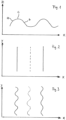
- In den Figuren zeigt
- Fig. 1
- eine schematische Seitenansicht eines wellenförmigen Elements aufweisend zumindest eine Welle, hier eine sinusoide Welle;
- Fig. 2
- eine Draufsicht auf das wellenförmige Element der
Fig. 1 , wobei die durchgezogenen Linien Wellenberge (positive Halbwelle) und die gestrichelten Linien Wellentäler (negative Halbwelle) symbolisieren; - Fig. 3
- zeigt eine Draufsicht auf ein Leichtbauelement der
Fig. 2 , wenn die Wellenberge und Wellentäler ihrerseits wellenförmig verformt sind; - Fig. 4
- eine Seitenansicht des Elements der
Fig. 3 , wenn die zweite Welle durch eine dritte Welle überlagert ist. - Fig. 5
- zeigt eine schematische perspektivische Darstellung der Anordnung der
Fig. 3 . - Ein Element, welches zur Herstellung eines erfindungsgemäßen Mehrschichtverbunds verwendbar ist, liegt so vor, dass es sich entlang einer - insbesondere ebenen - Fläche erstreckt, wobei das Element einen entlang der Fläche verlaufenden ersten wellenförmigen Verlauf einer ersten Welle mit sich entlang einer ersten Ausbreitungsrichtung veränderlichen Elongation aufweist, bei dem Wellenberge der Oberseite und Wellentäler der Unterseite des Elements entlang einer zweiten Richtung parallel zueinander angeordnet sind, wobei diese zweite Richtung in einem Winkel α mit 0°< α ≤ 90° , vorzugsweise ca. 90°, zur ersten Richtung und entlang dieser Fläche liegt, wobei das Element aus miteinander verbundenen Holzfasern besteht.
- Somit sind sowohl die Oberseite wie auch die Unterseite des Elements Bestandteil einer Welle. Auf der Oberseite befinden sich die Wellenberge und auf der Unterseite zugehörige Wellentäler. Die Wellenberge können auch als Wellenkämme bezeichnet werden.
- Der Begriff "Element" bedeutet ein Bauteil oder eine Komponente des erfindungsgemäßen Mehrschichtverbunds in Form einer Leichtbauplatte. Im Folgenden wird dieses Element auch als Leichtbauplattenelement bezeichnet.
- Der Begriff "Welle" im Element wird im physikalischen Sinn durch eine sich räumlich ausdehnende Schwingung veranschaulicht. In ihrer breitesten Bedeutung beschreiben die Begriffe "Welle" oder "Wellenstruktur"' oder "wellenförmig" oder "wellenartig" mindestens einen Wellenberg und ein Wellental in der Welle. Somit weist die Welle im mathematischen Sinn mindestens eine positive und negative Halbwelle auf.
- Die verwendeten Begriffe schließen auch sich wiederholende wellenförmige Struktureinheiten im Element ein.
- Die Welle kann im mathematischen Sinn durch die Elongation der Schwingung, durch die Amplitude der Schwingung wie auch durch die Schwingungsebene der positiven oder negativen Halbwelle, d.h. des Wellenbergs und des Wellentals, charakterisiert werden. Eine Charakterisierung über die Wellenlänge, also über die Länge eines Wellenbergs und des sich daran anschließenden Wellentals ist gleichfalls möglich. Der Übergang zwischen einem Wellenberg und einem Wellental kann - in Abhängigkeit von der Form der Welle - durch einen Wendepunkt im wellenförmigen Verlauf wie auch durch einen geraden Abschnitt charakterisiert werden.
- Die Welle kann bezüglich ihrer Amplitude oder Wellenlänge oder Amplitude und Wellenlänge variiert werden. Dadurch kann die Dicke der Kernschicht in der Leichtbauplatte ebenso beeinflusst werden wie ihre Steifigkeit. Andererseits ist es auch möglich, die Steifigkeit der Leichtbauplatte über Plattenparameter wie Dicke der Welle, d.h. die Dicke des wellenförmigen oder wellenartigen Elements in der Leichtbauplatte, der Span- und Fasergeometrie im Element, der Verdichtung der Elemente in der Platte wie auch des Verleimungsgrads der Elemente untereinander und mit den Deckschichten der Platte beeinflusst werden.
- Bei der Welle kann es sich sowohl um eine sich transversal (geradlinig) wie auch um eine sich radial ausbreitende oder verlaufende Welle handeln.
- Die Form der Welle kann dabei jegliche erdenkliche Struktur annehmen.
- In einer Ausführungsform ist die Welle in Form einer Sinus-Funktion oder einer Funktion ausgebildet, welche ähnlich einer Sinus-Funktion ist, d.h. sie liegt in Form einer Sinus-Funktion dar und/oder ist sinusoid. Im Folgenden werden die Begriffe "sinusförmig" oder "sinusoid" synonym verwendet.
- In einer weiteren Ausführungsform ist die Welle in Form einer Dreieckschwingung ausgebildet. Der Begriff "Dreieckschwingung" umfasst auch den Begriff "dreieckähnliche Schwingung".
- In einer weiteren Ausführungsform ist die Welle in Form einer Sägezahnschwingung ausgebildet. Eine derartige Schwingung kann auch als Kippschwingung bezeichnet werden.
- In einer weiteren Ausführungsform ist die Welle in Form einer Rechteckschwingung ausgebildet.
- Die genannten Wellenformen sind in der Physik bekannt und können auch mathematisch beschrieben werden.
- In einer weiteren Ausführungsform weist die Welle unterschiedliche Wellenformen auf, d.h. mindestens zwei, oder drei oder vier Wellenformen ausgewählt aus: Dreieckschwingung, sinusoide Schwingung, Sägezahnschwingung oder Rechteckschwingung.
- In einer Ausführungsform können diese Wellen in beliebiger Reihenfolge im wellenförmigen Element entlang einer gemeinsamen Ausbreitungsrichtung angeordnet sein.
- In einer weiteren Ausführungsform können sich auch zwei oder mehr der vorstehend genannten Schwingungsarten in einer gemeinsamen Ausbreitungsrichtung überlagern und eine entsprechend neue Wellenform ausbilden.
- Durch geeignete Überlagerung kann beispielweise eine trapezförmige Schwingung entstehen.
- Die Wellenform im wellenförmigen Element kann auch damit beschrieben werden, dass das wellenförmige Element in Form eines Leichtbauplattenelements plättchenförmige Bereiche aufweist, wobei ein plättchenförmiger Bereich im wellenförmigen Element mit einem angrenzenden plättchenförmigen Bereich im wellenförmigen Element eine gemeinsame Kante zwischen sich ausbildet, derart, dass das Element wellenförmig ausgebildet ist. Somit bilden die plättchenförmigen Bereiche einschließlich der Kante eine Welle aus.
- Der Begriff "plättchenförmige Bereiche" schließt Bereiche ein, die in Form von Flächen ausgebildet sind. Die Flächen können eben, d.h. plan, oder auch uneben sein, d.h. nicht plan, vorzugsweise dann gekrümmt, vorzugsweise konvex oder konkav, oder gewellt.
- Der Begriff "Kante" schließt Begriffe wie "Übergangsbereich zwischen zwei benachbarten plättchenförmigen Bereichen" ein. Dieser Übergangsbereich kann eine Kante sein, welche scharf ausgeprägt ist. Der Begriff schließt auch eine Kante ein, welche wie eine gekrümmte Fläche oder wie eine plane (ebene) Fläche ausgestaltet ist. Somit schließt der Begriff "Kante" eine scharfe Kante in Form einer Linie wie auch eine wellige oder gewellte Kante in der Form einer kurvenförmigen Ebene oder einen gekrümmten Bereich zwischen zwei plättchenförmigen Bereichen ein. Somit bilden die plättchenförmigen Bereiche im wellenförmigen Element eine wellenförmige Struktur aus, d.h. einem Wellental folgt ein Wellenberg und umgekehrt.
- Vorzugsweise sind Kanten, welche von benachbarten plättchenförmigen Bereichen im wellenförmigen Element gebildet werden, parallel zueinander ausgerichtet.
- Der Begriff "gekrümmt ausgebildete Fläche" bedeutet eine konvex ausgebildete Fläche oder eine konkav ausgebildete Fläche oder eine Fläche, die sowohl einen konvexen wie auch konkaven Anteil aufweist. Insbesondere bedeutet der Begriff "gekrümmt" auch "kontinuierlich gekrümmt".
- Somit wird auch ein wellenförmiges Element offenbart, welches plättchenförmige Bereiche aufweist, wobei ein plättchenförmiger Bereich im wellenförmigen Element mit einem angrenzenden plättchenförmigen Bereich im wellenförmigen Element eine gemeinsame Kante zwischen sich ausbildet, derart, dass das Element wellenförmig ausgebildet ist, wobei
- (a) die plättchenförmigen Bereiche plane Flächen sind und die zwischen den planen Flächen ausgebildete Kante eine Linie ist. Eine derartige Welle kann als zick-zack-Welle beschrieben werden; oder
- (b) die plättchenförmigen Bereiche plane Flächen sind und die zwischen den planen Flächen ausgebildete Kante eine gekrümmte Fläche ist; oder
- (c) die plättchenförmigen Bereiche plane Flächen sind und die zwischen den planen Flächen ausgebildete Kante ein plane Fläche ist; oder
- (d) die plättchenförmigen Bereiche gekrümmt ausgebildete Flächen sind und die zwischen den gekrümmten Flächen ausgebildete Kante eine gekrümmt ausgebildete Fläche ist, vorzugsweise eine konvex ausgebildete Fläche; oder
- (e) die plättchenförmigen Bereiche gekrümmt ausgebildete Flächen sind und die zwischen den gekrümmten Flächen ausgebildete Kante geradenförmig ist; oder
- (f) die plättchenförmigen Bereiche gekrümmt ausgebildete Flächen sind und die zwischen den gekrümmten Flächen ausgebildete Kante eine plan ausgebildete Fläche ist.
- In einer Ausführungsform weist die Welle mindestens eine oder zwei oder drei oder vier oder fünf oder sechs der Wellenformen (a) bis (f) auf.
- In einer Ausführungsform wird das Element gebildet aus
- (c') einem Element (c), derart, dass die Welle im Längsschnitt gesehen sich wiederholende Einheiten in Form eines Trapezes aufweist; oder
- (d') Elementen (d), derart, dass die Welle im Längsschnitt gesehen sich wiederholende Einheiten in Form einer Sinus-Funktion oder einer sinusoiden Funktion aufweist.
- Die gute Druck- und Schubfestigkeit und -steifigkeit der Elemente (a) bis (f) bzw. einer Kernschicht enthaltend diese Elemente oder ein Mehrschichtverbund enthaltend die Kernschicht lässt sich noch deutlich verbessern, wenn die Kernschicht insbesondere Elemente (d') enthält oder aus diesen Elementen besteht.
- Derartige Wellenformen sind bekannt und sind in der
EP 2 660 408 A1 und derWO 2015/067362 beschrieben. Zur weiteren Erläuterung wird deshalb ausdrücklich auf diese Dokumente hingewiesen. - In einer erfindungsgemäßen Ausführungsform werden die mindestens eine positive und negative Halbwelle, d.h. der Wellenberg und das Wellental, von einer zweiten Welle überlagert.
- Dies bedeutet auch, dass die erste Welle und damit das Leichtbauplattenelement unter Bildung der zweiten Welle deformiert oder verformt sind.
- Die Form der zweiten Welle kann unabhängig von der Form der ersten Welle unter den Formen gewählt werden, welche in Bezug auf die erste Welle weiter oben beschrieben sind.
- In einer Ausführungsform verläuft, wenn sich die erste Welle in einem kartesischen Koordinatensystem mit den Raumachsen x, y und z in x-Richtung ausbreitet und die Schwingungsebene in oder parallel zur x,z-Ebene liegt, die Schwingungsebene der ersten Welle senkrecht zur Schwingungsebene der zweiten Welle, wobei die zweite Welle sich in y-Richtung ausbreitet und die Schwingungsebene in oder parallel zur y,z-Ebene liegt.
- In einer bevorzugten Ausführungsform verläuft, wenn sich die erste Welle in einem kartesischen Koordinatensystem mit den Raumachsen x, y und z in x-Richtung ausbreitet und die Schwingungsebene in oder parallel zur x,z-Ebene liegt, die Schwingungsebene der ersten Welle senkrecht zur Schwingungsebene der zweiten Welle, wobei die zweite Welle sich in y-Richtung ausbreitet und die Schwingungsebene in oder parallel zur x,y-Ebene liegt.
- In einer weiteren bevorzugten Ausführungsform wird die zweite Welle und damit das Leichtbauplattenelement unter Bildung der dritten Welle weiter deformiert und verformt.
- Somit werden die zweite Welle und damit auch die erste Welle von einer dritten Welle überlagert.
- Selbstverständlich ist es auch denkbar, die dritte Welle und damit auch die erste und die zweite Welle mit einer vierten Welle zu überlagern, oder die vierte Welle und damit auch die erste, die zweite und die dritte Welle ihrerseits mit einer fünften Welle zu überlagern, usw.
- Die Form der dritten Welle kann unabhängig von der Form der ersten Welle und der zweiten Welle unter den Formen gewählt werden, welche in Bezug auf die erste und die zweite Welle weiter oben beschrieben sind.
- Vorzugsweise verläuft die Schwingungsebene der dritten Welle parallel zur Schwingungsebene der ersten Welle.
- In einer weiteren Ausführungsform verlaufen die Schwingungsebene der ersten Welle und die Schwingungsebene der zweiten Welle senkrecht zueinander, wobei die Schwingungsebene der dritten Welle parallel zur Schwingungsebene der ersten Welle verläuft.
- In einer bevorzugten Ausführungsform verläuft, wenn sich die erste Welle in einem kartesischen Koordinatensystem mit den Raumachsen x, y und z in x-Richtung ausbreitet und die Schwingungsebene in oder parallel zur x,z-Ebene liegt, die Schwingungsebene der ersten Welle senkrecht zur Schwingungsebene der zweiten Welle, wobei die zweite Welle sich in y-Richtung ausbreitet und die Schwingungsebene in oder parallel zur x,y-Ebene liegt, und die Schwingungsebene der dritten Welle in oder parallel zur y,z-Ebene liegt, wobei sich die dritte Welle in y-Richtung ausbreitet.
- Mit einer derartigen Ausführungsform kann die Stabilität der Elemente und damit die Stabilität der Leichtbauplatte weiter verbessert werden. Ein solches Element weist eine vergleichsweise erhöhte Steifigkeit auf, da im Element eine Art von "Aussteifungsrippen" erzeugt wird. Zusätzlich vermindert die Dreifachwellung weiter die Wahrscheinlichkeit des Ineinandergleitens von Wellenbergen bzw. Wellentälern benachbarter übereinanderliegender Elemente bei der Herstellung der Leichtbauplatte, wenn diese Elemente eine gleiche oder ähnliche Grundausrichtung aufweisen.
- Das wellenförmige Element besteht aus miteinander verbundenen Holzfasern .
- Der Begriff "Faser" bedeutet ein im Verhältnis zu seiner Länge dünnes und flexibles Gebilde. Vorzugsweise kann das Verhältnis von Länge zu Durchmesser mindestens zwischen 3:1 und 10:1 liegen.
- Das Leichtbauplattenelement weist einen Kleber auf. Mit Hilfe des Klebers werden die Fasern zur Erhöhung der Festigkeit miteinander verbunden.
- Die Erfindung offenbart des Weiteren ein Leichtbauplattenelement, das sich entlang einer - insbesondere ebenen - Fläche erstreckt, wobei das Leichtbauplattenelement einen entlang der Fläche verlaufenden ersten wellenförmigen Verlauf einer ersten Welle mit sich entlang einer ersten Ausbreitungsrichtung veränderlichen Elongation aufweist, bei dem Wellenberge der Oberseite und Unterseite des Leichtbauplattenelements entlang einer zweiten Richtung parallel zueinander angeordnet sind, wobei diese zweite Richtung in einem Winkel α mit 0°< α ≤ 90°, vorzugsweise ca. 90°, zur ersten Richtung und entlang dieser Fläche liegt, und wobei diesem ersten wellenförmigen Verlauf ein zweiter wellenförmiger Verlauf einer zweiten Welle des Leichtbauplattenelements überlagert ist, so dass die Wellenberge des ersten wellenförmigen Verlaufs eine weitere Wellung entlang mindestens dieser zweiten Richtung aufweisen,
und wobei das Leichtbauplattenelement aus miteinander verbundenen Holzfasern besteht. - Für die Erfindung brauchbare Leichtbauplattenelemente wie vorstehend definiert können allgemein nach einem Verfahren hergestellt werden, aufweisend mindestens die Stufen (A) und (B) oder (A) und (C):
- (A) Anordnen von Fasern, derart, dass sich die Fasern berühren;
- (B) Verpressen der sich berührenden Fasern der Stufe (A) in einem Presswerkzeug, wobei das Presswerkzeug so ausgestaltet ist, dass das nach dem Verpressen erhaltene wellenförmige Element die erste Welle oder die zweite Welle oder die dritte Welle aufweist; oder
- (C) Verpressen der sich berührenden Fasern der Stufe (A) in einem Presswerkzeug und Führen der verpressten Fasern und/oder Späne durch ein Profilierwerkzeug, wobei das Profilierwerkzeug so ausgestaltet ist, dass das nach dem Durchführen erhaltene Leichtbauplattenelement die erste Welle oder die zweite Welle oder die dritte Welle aufweist.
- Somit kann das in den Stufen (B) oder (C) erhaltene Element die erste Welle, die von der zweiten Welle überlagerte erste Welle oder die von der zweiten Welle überlagerte erste Welle aufweisen, wobei die zweite Welle ihrerseits von der dritten Welle überlagert ist.
- In einer Ausführungsform ist es möglich, in Stufe (A) die Fasern im Presswerkzeug anzuordnen. Damit weist die Stufe (A) die Stufe (A1) und die Stufe (B) die Stufe (B1) auf:
- (A1) Anordnen von Fasern, derart, dass sich die Fasern berühren, wobei die Fasern in einem Presswerkzeug angeordnet werden;
- (B1) Verpressen der sich berührenden Fasern der Stufe (A1) im Presswerkzeug, wobei das Presswerkzeug so ausgestaltet ist, dass das nach dem Verpressen erhaltene wellenförmige Element die erste Welle oder die zweite Welle oder die dritte Welle aufweist.
- In einer weiteren Ausführungsform ist es möglich, in Stufe (A) die Fasern anzuordnen, derart, dass sich die Fasern berühren, und diese flach oder eben zu verpressen und dann das verpresste Material der Stufe (B) zuzuführen.
- Demzufolge weist dann die Stufe (A) die Stufe (A2) und die Stufe (B) die Stufe (B2) auf:
- (A2) Anordnen von Fasern, derart, dass sich die Fasern berühren, wobei die Fasern so verpresst werden, dass eine flache Anordnung entsteht;
- (B2) Verpressen der verpressten Fasern der Stufe (A2) in einem Presswerkzeug, wobei das Presswerkzeug so ausgestaltet ist, dass das nach dem Verpressen erhaltene wellenförmige Element die erste Welle oder die zweite Welle oder die dritte Welle aufweist.
- Das Leichtbauplattenelement kann nach einem Verfahren hergestellt werden, aufweisend mindestens die Stufen (A) und (B) oder (A) und (C):
- (A) Anordnen von Holzfasern, derart, dass sich die Fasern;
- (B) Verpressen der sich berührenden Fasern der Stufe (A) in einem Presswerkzeug, wobei das Presswerkzeug so ausgestaltet ist, dass das nach dem Verpressen erhaltene Leichtbauplattenelement die erste Welle oder die zweite Welle oder die dritte Welle aufweist; oder
- (C) Verpressen der sich berührenden Fasern der Stufe (A) in einem Presswerkzeug und Führen der verpressten Fasern durch ein Profilierwerkzeug, wobei das Profilierwerkzeug so ausgestaltet ist, dass das nach dem Durchführen erhaltene Leichtbauplattenelement die erste Welle oder die zweite oder die dritte Welle aufweist.
- Die in Stufe (A) verwendeten Holzfasern bei der Herstellung des Leichtbauelements fallen beispielsweise in der holzverarbeitenden Industrie an.
- In einer Ausführungsform weist das Presswerkzeug der Stufe (B) Erhebungen und Vertiefungen auf, die beim Verpressen die Fasern zumindest teilweise kontaktieren. Mit Hilfe geeigneter Erhebungen und Vertiefungen können die erste Welle und die zweite und gegebenenfalls die dritte Welle des Leichtbauplattenelements erfindungsgemäß ausgestaltet werden, vorzugsweise geprägt werden.
- Geeignete Pressvorrichtungen und Verfahren zur Ausgestaltung von Elementen aufweisend eine Welle sind beispielsweise aus der
EP 2 488 337 B1 bekannt. Geeignete Pressvorrichtungen zur Herstellung des Leichtbauplattenelements können entsprechend ausgestaltet werden. - In einer Ausführungsform weist das Presswerkzeug der Stufe (B) keine Erhebungen und Vertiefungen auf. Dann wird in die Fasern oder Späne keine Wellenstruktur eingeprägt. Sie können dann in Stufe (C) durch ein geeignetes Profilierwerkzeug geleitet werden, welches dann die Wellenstruktur ausformt.
- In einer Ausführungsform weist das Profilierwerkzeug der Stufe (C) ein oder mehrere Profilierwalzen auf. Mit Hilfe geeigneter Profilierwalzen können die Wellen des Leichtbauplattenelements erfindungsgemäß ausgestaltet werden.
- Die beim Verpressen verwendeten Drucke können den Erfordernissen angepasst werden. In einer Ausführungsform liegt der Druck im Bereich von 5 bis 15 MPa. Die Verwendung höherer oder niedrigerer Drucke ist in anderen Ausführungsformen möglich.
- In Stufe (A) werden die Fasern zumindest teilweise mit einem Klebstoff kontaktiert. Damit kann die Stabilität der Elemente weiter erhöht werden.
- Das nach dem Verfahren hergestellte Element ist bezüglich seiner Abmessungen nicht begrenzt. Es können runde oder rundliche Leichtbauplattenelemente wie auch polygonale Leichtbauplattenelemente hergestellt werden.
- Vorzugsweise werden rechteckige Leichtbauplattenelemente hergestellt, die über eine Länge und Breite definiert sind.
- In einer Ausführungsform werden in Stufe (B) oder (C) verpresste Fasern eingesetzt, die so dimensioniert sind, dass das Verhältnis von Länge zur Breite des hergestellten Leichtbauplattenelements im Bereich von 2 : 1 bis 50 : 1 liegt, weiter bevorzugt im Bereich von 2 : 1 bis 40 : 1.
- In einer Ausführungsform liegt im Leichtbauplattenelement das Produkt aus Länge x Breite im Bereich von 10 mm x 5 mm bis 3000 mm x 1000 mm.
- Somit können in einer Ausführungsform relative kleine Leichtbauplattenelemente wie auch bahnförmige Leichtbauplattenelemente hergestellt werden.
- In einer weiteren Ausführungsform können relativ große Leichtbauplattenelemente, die vorzugsweise bahnförmig ausgestaltet sind, einem Zerkleinerungsschritt unterzogen werden, falls aus diesen bahnförmigen Elementen relativ kleine Leichtbauplattenelemente hergestellt werden sollen.
- Relativ kleine Leichtbauplattenelemente weisen vorzugsweise ein Produkt aus Länge x Breite im Bereich von 10 x 5 mm bis 200 x 100 mm auf, weiter bevorzugt 10 x 5 mm bis 100 x 50 mm, weiter bevorzugt 10 x 5 mm bis 50 x25 mm. Der Begriff "Länge" bedeutet den kürzesten Abstand zwischen Anfang und Ende des wellenförmigen Elements in Längsrichtung des Elements. Der Begriff "Breite" bedeutet den Abstand zwischen den Seitenrändern quer zur Längsrichtung des Elements.
- Vorzugsweise werden in Stufe (A) Fasern in das Verfahren eingesetzt, die so dimensioniert ist, dass das nach dem Verfahren erhaltene Element gemäß der Stufen (B) oder (C) eine Dicke im Bereich von 0,1 bis 5 mm aufweist, vorzugsweise 0,2 mm bis 3,5 mm, weiter bevorzugt 0,2 mm bis 2 mm.
- Der Begriff "Dicke" bedeutet den kleinsten Abstand zwischen zwei einander gegenüber liegenden Oberflächen eines wellenförmigen Elements. Diese Oberflächen sind durch die Dicke der plättchenförmigen Bereiche oder der Kante voneinander beabstandet.
- Die Dicke der Wellenbahn muss nicht notwendigerweise an allen Stellen der Welle gleich sein. Es ist möglich, dass die Wellenberge und Wellentäler bzw. gerade Abschnitte zwischen Wellenbergen und Wellentälern unterschiedliche Dicken aufweisen. Auch ist es durch die verwendete Presstechnik möglich, dass in der Welle Bereiche unterschiedlicher Dicke auftreten.
- Vorzugsweise wird das Verfahren so durchgeführt, dass die Vertiefungen und Erhebungen des Presswerkzeugs der Stufe (B) bzw. das Profil des profilierten Werkzeugs der Stufe (C) so gewählt werden, dass die Wellenhöhe des Leichtbauplattenelements im Bereich von 1 bis 20 mm liegt, vorzugsweise 2 bis 12 mm, mehr bevorzugt 2 bis 8 mm.
- Der Begriffe "Wellenhöhe" bedeutet dabei den kleinsten Abstand zwischen zwei imaginären, zueinander parallelen Ebenen, zwischen die das wellenförmige Element angeordnet werden kann, derart, dass die Wellen zwischen diesen Ebenen liegen.
- In einer besonders bevorzugten Ausführungsform liegt die Dicke des wellenförmigen Elements im Bereich von 0,2 bis 5 mm und die Wellenhöhe liegt im Bereich von 2 bis 15 mm.
- In einer weiteren besonders bevorzugten Ausführungsform liegt die Dicke des wellenförmigen Elements im Bereich von 0,2 bis 2 mm und die Wellenhöhe liegt im Bereich von 2 bis 8 mm.
- Die nach dem Verfahren hergestellten Leichtbauplattenelemente weisen vorzugsweise eine Rohdichte im Bereich von 150 bis 430 kg/m3 auf.
- Die hergestellten wellenförmigen Elemente besitzen eine ausgezeichnete Tragfähigkeit, so dass sie als oder für eine aufgelockerte Kernschicht bzw. in Mehrschichtverbunden mit aufgelockerter Kernschicht verwendet werden können, die ihrerseits bei relativ geringer Dichte eine hohe Tragfähigkeit erlauben.
- Kernschichten wie hierin offenbart weisen Leichtbauplattenelemente auf wie vorstehend definiert, oder weisen Leichtbauplattenelemente auf hergestellt nach einem Verfahren wie vorstehend definiert.
- Der Begriff "Kernschicht" bedeutet eine Schicht, welche neben den Leichtbauplattenelementen zusätzlich Hohlräume aufweist, also eine aufgelockerte Struktur aufweist.
- Der Begriff "Schicht" wird synonym zum Begriff "Lage" verwendet.
- In einer Ausführungsform sind die Leichtbauplattenelemente in der Kernschicht in mindestens einer ersten und einer zweiten Schicht angeordnet und zumindest teilweise miteinander verklebt.
- In einer weiteren Ausführungsform enthalten die mindestens eine erste und die zweite Schicht jeweils eine Vielzahl von Leichtbauplattenelementen.
- In einer Ausführungsform sind die Leichtbauplattenelemente in der mindestens einen ersten Schicht und der zweiten Schicht zumindest teilweise jeweils regellos angeordnet. Diese Ausführungsform ist insbesondere dann von Vorteil, wenn die Leichtbauplattenelemente relativ kleine Abmessungen aufweisen.
- In einer weiteren bevorzugten Ausführungsform enthalten die mindestens eine erste und die zweite Schicht der Kernschicht jeweils nur ein Leichtbauplattenelement. Vorzugsweise werden in dieser Ausführungsform dann bahnförmige Leichtbauplattenelemente eingesetzt.
- In dieser Ausführungsform kann der Winkel zwischen der ersten Richtung der ersten Welle in der ersten Schicht und der ersten Richtung der ersten Welle in der zweiten Schicht 90° betragen. Der Begriff "Winkel von 90°" lässt auch Abweichungen von ± 10° zu.
- Vorliegend wird ein Verfahren zur Herstellung einer Kernschicht wie vorstehend definiert offenbart, aufweisend mindestens die Stufen (D) bis (F):
- (D) Anordnen mindestens eines Leichtbauplattenelements wie vorstehend definiert, oder hergestellt nach einem Verfahren wie vorstehend definiert, wobei das mindestens eine wellenförmige Element eine erste Schicht ausbildet;
- (E) Anordnen mindestens eines zweiten Leichtbauplattenelements wie vorstehend definiert, oder hergestellt nach einem Verfahren wie vorstehend definiert, auf der ersten Schicht, wobei das auf der ersten Schicht angeordnete mindestens eine Leichtbauplattenelement eine zweite Schicht ausbildet, derart, dass die erste und die zweite Schicht zumindest teilweise zwei übereinander liegende Schichten ausbilden;
- (F) zumindest teilweises Verkleben der Leichtbauplattenelemente untereinander.
- Das mindestens eine Leichtbauplattenelement wird in Stufe (D) auf einem geeigneten Träger angeordnet. Der Träger ist vorzugsweise ein Material mit einer ebenen Fläche, auf der das oder die Elemente angeordnet werden können.
- Das Verfahren kann weiter mindestens die Stufe (E1) aufweisen:
(E1) Anordnen mindestens eines weiteren Leichtbauplattenelements wie vorstehend definiert, oder hergestellt nach einem Verfahren wie vorstehend definiert auf der zweiten Schicht der Stufe (E), wobei das auf der zweiten Schicht angeordnete Leichtbauplattenelement zumindest teilweise eine dritte Schicht ausbildet, derart, dass die zweite und die dritte Schicht zumindest teilweise zwei übereinander liegende Schichten ausbilden. - Das feste Verbinden der Stufe (F) kann durch Anlegen von Druck erleichtert werden. Dieser liegt vorzugsweise im Bereich von 0,02 MPa bis 4,0 MPa, mehr bevorzugt im Bereich von 0,01 bis 3,0 MPa.
- Die Erfindung offenbart einen Mehrschichtverbund, mindestens aufweisend eine erste Deckschicht oder eine erste und eine zweite Deckschicht und eine Kernschicht, wobei die Kernschicht eine Kernschicht ist wie vorstehend definiert, oder eine Kernschicht ist wie vorstehend beschriebenhergestellt, wobei die Kernschicht mit der ersten Deckschicht oder der ersten Deckschicht und der zweiten Deckschicht verklebt ist, wobei sich die Kernschicht zwischen der ersten und der zweiten Deckschicht befindet, wenn der Mehrschichtverbund die zweite Deckschicht aufweist.
- Damit sind die erste Deckschicht oder die erste und die zweite Deckschicht mit der Kernschicht flächig verklebt.
- In einer Ausführungsform weist/weisen die erste oder die zweite oder die erste und die zweite Deckschicht jeweils zwei durch eine Dicke voneinander beabstandete Seiten auf, und die Seite, welche mit dem mindestens einen Element verklebt ist, ist profiliert.
- Das Profil kann in einer Wellenstruktur vorliegen. Das Profil kann über geeignete Werkzeuge in die Deckschicht eingebracht werden.
- Dies hat den Vorteil, dass zur Gewichtsersparnis weitere Hohlräume in den Mehrschichtverbund eingebracht werden können, ohne die Stabilität des Verbunds zu stark nachteilig zu beeinflussen.
- Vorzugsweise weist/weisen die erste Deckschicht oder die zweite Deckschicht oder die erste Deckschicht und die zweite Deckschicht unabhängig voneinander ein Material auf ausgewählt aus: Furnier, Holzplatte wie Holzwerkstoffplatte oder Massivholzplatte, Spanplatte, Faserplatte, Sperrholzplatte, Kunststoffplatte, Gipskarton, Blech, Faserzementplatte, und aus zwei oder mehr davon.
- Vorzugsweise ist mindestens eine Deckschicht eben, d.h. ebenflächig.
- Die Deckschichten sind hinsichtlich ihrer Form nicht limitiert.
- Vorzugsweise weist mindestens eine Deckschicht eine quadratische oder eine rechteckige Form auf.
- Die Abmessungen der Deckschicht sind nicht limitiert.
- Vorzugsweise liegen bei rechteckigen Formen die Breite und die Länge jeweils im Bereich von 0,50 m bis 5 m, weiter bevorzugt im Bereich von 1 bis 3 m.
- In einer erfindungsgemäßen Ausführungsform weist der Mehrschichtverbund eine Kernschicht auf, die lediglich ein wellenförmiges Leichtbauelement aufweist oder aus diesem besteht, wie in Anspruch 1 definiert.
- Demzufolge betrifft die Erfindung auch einen Mehrschichtverbund, mindestens aufweisend eine erste Deckschicht oder eine erste und eine zweite Deckschicht, eine Kernschicht und Hohlräume zwischen der Kernschicht und der Deckschicht oder den Deckschichten, wobei die Kernschicht lediglich ein Leichtbauplattenelement aufweist oder aus diesem besteht, wie vorstehend definiert, oder ein Leichtbauplattenelement hergestellt nach einem Verfahren wie vorstehend definiert, wobei die Kernschicht mit der ersten Deckschicht oder der ersten Deckschicht und der zweiten Deckschicht verklebt ist, wobei sich die Kernschicht zwischen der ersten und der zweiten Deckschicht befindet, wenn der Mehrschichtverbund die zweite Deckschicht aufweist.
- Weist die Kernschicht des Mehrschichtverbunds lediglich ein Leichtbauelement auf oder besteht aus diesem einen Leichtbauelement, kann zur Herstellung des Leichtbauverbundes ein Verfahren eingesetzt werden, das lediglich das Anordnen und Verkleben des einen Leichtbauelements auf der ersten Deckschicht vorsieht, wobei optional die zweite Deckschicht mit der Kernschicht verklebt werden kann.
- In einer Ausführungsform kann die Kernschicht wie vorstehend definiert oder hergestellt nach dem Verfahren wie vorstehend definiert einem Schritt der Druckverformung unterworfen werden, wobei dreidimensionale Objekte hergestellt werden können. Dazu kann die Kernschicht in einem geeigneten Presswerkzeug verformt werden. Diese Verformung kann während der Herstellung der Kernschicht wie auch im Anschluss daran erfolgen.
- In einer Ausführungsform werden lediglich die Kanten der Kernschicht verformt, vorzugsweise durch Komprimieren. Damit ist es möglich, die Hohlräume an den Kanten der Kernschicht abzudichten. Dieses Druckverformen kann durchgeführt werden während des Zusammenfügens der Kernschicht, jedoch auch im Anschluss an das Zusammenfügen der Kernschicht in einer nachgeschalteten Stufe, beispielsweise durch thermisches Erweichen des Klebers an den Kanten. Diese Ausführungsform hat den Vorteil, dass eine Riegelstruktur in die Kernschicht bzw. den Kanten der Kernschicht eingebracht werden kann.
- Beim Komprimieren ergibt sich die Möglichkeit, den Randteil der Kernschicht mit einem balligen Profil, also einem gerundeten Profil, zu versehen. Dies ist z.B. bei hochwertigen Möbelbauteilen häufig wünschenswert.
- In einer weiteren Ausführungsform können nicht nur der Kantenbereich sondern zusätzlich oder getrennt vom Kantenbereich auch weitere Bereiche der Kernschicht druckverformt werden.
- Ein Verfahren zur Herstellung dreidimensionaler Holzgegenstände durch Druckverformung wird in der
DD 271870 DE 101 24 912 beschrieben. Die dain genannten Verfahrensbedingungen können auch auf die erfindungsgemäße Kernschicht angewendet werden. - Somit wird eine verformte Kernschicht offenbart, aufweisend Leichtbauplattenelemente wie vorstehend definiert, oder aufweisend Leichtbauplattenelemente hergestellt nach einem Verfahren wie vorstehend definiert, wobei die Leichtbauplattenelemente zumindest teilweise verformt sind, herstellbar durch ein Verfahren mindestens aufweisend die Stufe (U):
(U) Druckverformen der Kernschicht wie vorstehendd definiert oder der Kernschicht hergestellt nach einem Verfahren wie vorstehend definiert. - In einer Ausführungsform kann auch der erfindungsgemäße Mehrschichtverbund wie vorstehend definiert oder hergestellt nach dem Verfahren wie vorstehend definiert einem Schritt der Druckverformung unterworfen werden, wobei dreidimensionale Objekte hergestellt werden können. Diese Druckverformung kann in einer Weise durchgeführt werden vorstehend definiert.
- Demzufolge offenbart die Erfindung somit einen verformten Mehrschichtverbund, mindestens aufweisend eine erste Deckschicht oder eine erste und eine zweite Deckschicht, wobei die Kernschicht eine Kernschicht ist wie vorstehend
definiert, oder eine Kernschicht ist hergestellt nach einem Verfahren wie vorstehend definiert, wobei die Kernschicht mit der ersten Deckschicht oder mit der ersten und der zweiten Deckschicht verklebt ist, wobei sich die Kernschicht zwischen der ersten und der zweiten Deckschicht befindet, wenn der Mehrschichtverbund die zweite Deckschicht aufweist, wobei die Kernschicht und die erste Deckschicht oder die Kernschicht, die erste und die zweite Deckschicht zumindest teilweise verformt sind, mindestens aufweisend die Stufe (V):
(V) Druckverformen des Mehrschichtverbunds wie vorstehend definiert, oder des Mehrschichtverbunds hergestellt nach einem Verfahren wie vorstehend beschrieben. - Die Erfindung betrifft die Verwendung eines Mehrschichtverbunds wie vorstehend definiert im Rohbau, Hochbau, Fertigbau, Ausbau, Innenausbau, zum Schall- und Wärmeschutz, für Inneneinrichtungen, Möbel, Türen und Türfüllungen, Dekorationen, im Fahrzeugbau, Caravanbau, Schiffsinnenausbau, Flugzeuginnenausbau und in der Verpackungstechnik.
- Elemente, die dem Verständnis der Erfindung behilflich sind, sind in den Zeichnungen schematisch dargestellt. Sie werden im Folgenden mit Bezug zu den Figuren der Zeichnungen näher erläutert.
-
-
Fig. 1 zeigt eine schematische Seitenansicht eines Leichtbauelements aufweisend zumindest eine Welle, hier eine sinusoide Welle. Die Welle breitet sich in einem kartesischen Koordinatensystem in x-Richtung aus, wobei die Schwingungsebene der Welle in oder parallel zur x,z-Ebene liegt. Die Welle kann auch so beschrieben werden, dass plättchenförmige Bereiche a und b vorliegen, welche eine gemeinsame Kante c zwischen sich einschließen. Die plättchenförmigen Bereiche sind gekrümmt ausgebildet, wobei auch die Kante eine gekrümmt ausgebildete Fläche ist. -
Fig. 2 zeigt eine Draufsicht auf die x,y-Ebene des Leichtbauelements derFig. 1 , wobei die durchgezogenen Linien Wellenberge (positive Halbwellen) und die gestrichelten Linien Wellentäler (negative Halbwellen) symbolisieren. -
Fig. 3 zeigt eine Draufsicht auf die x,y-Ebene des Leichtbauelements derFig. 2 , wobei die Wellenberge und Wellentäler der ersten Welle verformt sind, d.h. von einer zweiten Welle überlagert werden, wobei die zweite Welle sinusoid ist. Hierbei liegt, wenn sich die erste Welle in einem kartesischen Koordinatensystem mit den Raumachsen x, y und z in x-Richtung ausbreitet und die Schwingungsebene der ersten Welle parallel zur x,z-Ebene liegt, die Schwingungsebene der ersten Welle senkrecht zur Schwingungsebene der zweiten Welle, wobei sich die zweite Welle in y-Richtung ausbreitet und die Schwingungsebene in oder parallel zur x,y-Ebene liegt. -
Fig. 4 zeigt eine Seitenansicht auf ein Leichtbauplattenelement ausgehend vom Leichtbauplattenelement der derFig. 3 , wobei die zweite Welle verformt ist, d.h. von einer dritten Welle überlagert wird, wobei die dritte Welle sinusoid ist. Hierbei liegt, wenn sich die erste Welle in einem kartesischen Koordinatensystem mit den Raumachsen x, y und z in x-Richtung ausbreitet und die Schwingungsebene parallel zur x,z-Ebene liegt, die Schwingungsebene der ersten Welle senkrecht zur Schwingungsebene der zweiten Welle, wobei sich die zweite Welle in y-Richtung ausbreitet und die Schwingungsebene in oder parallel zur x,y-Ebene liegt, wobei die Schwingungsebene der dritten Welle parallel zur y,z-Ebene liegt, wobei sich die dritte Welle in y-Richtung ausbreitet. -
Fig. 4 zeigt auch eine Seitenansicht auf ein Leichtbauplattenelement ausgehend vom Leichtbauplattenelement derFig. 2 , wobei die erste Welle verformt ist, d.h. von einer zweiten Welle überlagert wird. Hierbei liegt, wenn sich die erste Welle in einem kartesischen Koordinatensystem mit den Raumachsen x, y und z in x-Richtung ausbreitet und die Schwingungsebene in oder parallel zur x,z-Ebene liegt, die Schwingungsebene der ersten Welle senkrecht zur Schwingungsebene der zweiten Welle, wobei die zweite Welle sich in y-Richtung ausbreitet und die Schwingungsebene der zweiten Welle in oder parallel zur y,z-Ebene liegt. -
Fig. 5 zeigt eine schematische perspektivische Darstellung der Anordnung derFig. 3 . Die sinusoide erste Welle ist dabei von einer sinusoiden zweiten Welle überlagert bzw. die Wellenberge und Wellentäler der sinusoiden ersten Welle sind ihrerseits sinusoid gewellt. - In einem Anwendungsbeispiel wurden einseitig ebenflächige und auf der Gegenseite mit Wellenprofil versehene, 5 mm dicke, großformatige Deckschichten aus einem Gemisch von Spanplatten-Deckschichtspänen und Spanplattenleim mittels einer entsprechend profilierten, beheizten Pressplatte bei einer Presstemperatur von 180 °C und einer Presszeit von 4 Minuten gepresst. Die Wellenhöhe betrug 3,5 mm bei einer Wellenlänge von 6 mm.
- Parallel dazu wurden großformatige Wellenelemente mit den gleichen Wellenmaßen und einer Dicke von 0,6 mm und dem gleichen Ausgangsmaterial mittels eines entsprechend profilierten Pressplattenpaares hergestellt. Nach dem Pressen erfolgte die Beleimung der Wellenberge und Wellentäler in einer Walzenbeleimmaschine. Es folgte das Zerteilen in 40 mm breite Streifen mittels Rollenschneidern und das anschließende Brechen in 30 bis 45 mm lange Partikel. Diese Partikel (Leichtbauplattenelemente) wurden von einer Streumaschine in Schichten auf die zuvor gefertigte, mit dem Wellenprofil nach oben zeigende Deckschicht bis zu einer Höhe von 28 mm gestreut. Schließlich wurde die obere Deckschicht aufgelegt und das Presspaket bei einer Temperatur von 180 °C und einer Verdichtung bis auf 25 mm gepresst.
- Es wurde eine Leichtbauplatte mit einer Dichte von 250 kg/m3 und einer geschlossenen, mit Furnier oder Folie beschichtbaren Oberfläche erhalten.
Claims (12)
- Mehrschichtverbund, mindestens aufweisend eine erste Deckschicht oder eine erste und eine zweite Deckschicht, eine Kernschicht und Hohlräume zwischen der Kernschicht und der Deckschicht oder den Deckschichten,wobei die Kernschicht aus einem Leichtbauplattenelement besteht,wobei das Leichtbauplattenelement sich entlang einer - insbesondere ebenen - Fläche erstreckt,wobei das Leichtbauplattenelement einen entlang der Fläche verlaufenden ersten wellenförmigen Verlauf einer ersten Welle mit sich entlang einer ersten Ausbreitungsrichtung veränderlichen Elongation aufweist, bei dem Wellenberge der Oberseite und Unterseite des Leichtbauplattenelements entlang einer zweiten Ausbreitungsrichtung parallel zueinander angeordnet sind, wobei diese zweite Ausbreitungsrichtung in einem Winkel α mit 0°< α ≤ 90°, vorzugsweise ca. 90°, zur ersten Ausbreitungsrichtung und entlang der Fläche liegt,wobei die Kernschicht mit der ersten Deckschicht oder der ersten Deckschicht und der zweiten Deckschicht flächig verklebt ist, wobei sich die Kernschicht zwischen der ersten Deckschicht und der zweiten Deckschicht befindet, wenn der Mehrschichtverbund die zweite Deckschicht aufweist; undwobei die Deckschicht oder eine der Deckschichten ebenflächig ist;wobei das Leichtbauplattenelement eine Dicke im Bereich von 0,1 bis 5 mm aufweist, wobei der Begriff "Dicke" den kleinsten Abstand zwischen zwei einander gegenüber liegenden Oberflächen des Leichtbauplattenelements bedeutet,dadurch gekennzeichnet, dass das Leichtbauplattenelement aus Holzfasern und Kleber besteht und, dass die Holzfasern mit Hilfe des Klebers zur Erhöhung der Festigkeit des Leichtbauplattenelements miteinander verbunden werden.
- Mehrschichtverbund nach Anspruch 1,
wobei dem ersten wellenförmigen Verlauf ein zweiter wellenförmiger Verlauf einer zweiten Welle des wellenförmigen Leichtbauplattenelements überlagert ist, so dass die Wellenberge und Wellentäler des ersten wellenförmigen Verlaufs eine weitere Wellung entlang mindestens der zweiten Ausbreitungsrichtung aufweisen. - Mehrschichtverbund nach Anspruch 1 oder 2,
wobei dem zweiten wellenförmigen Verlauf der zweiten Welle ein dritter wellenförmiger Verlauf einer dritten Welle überlagert ist. - Mehrschichtverbund nach einem der Ansprüche 2 oder 3, wobei, wenn sich die erste Welle in einem kartesischen Koordinatensystem mit den Raumachsen x, y und z in x-Richtung ausbreitet und die Schwingungsebene der ersten Welle parallel zur x,z-Ebene liegt, die Schwingungsebene der ersten Welle senkrecht zur Schwingungsebene der zweiten Welle liegt, wobei sich die zweite Welle in y-Richtung ausbreitet und deren Schwingungsebene parallel zur y,z-Ebene liegt.
- Mehrschichtverbund nach einem der Ansprüche 2 oder 3, wobei, wenn sich die erste Welle in einem kartesischen Koordinatensystem mit den Raumachsen x, y und z in x-Richtung ausbreitet und die Schwingungsebene der ersten Welle parallel zur x,z-Ebene liegt, die Schwingungsebene der ersten Welle senkrecht zur Schwingungsebene der zweiten Welle liegt, wobei sich die zweite Welle in y-Richtung ausbreitet und deren Schwingungsebene parallel zur x,y-Ebene liegt.
- Mehrschichtverbund nach Ansprüchen 3 und 5, wobei die Schwingungsebene der dritten Welle parallel zur y,z-Ebene liegt, wobei sich die dritte Welle in y-Richtung ausbreitet.
- Mehrschichtverbund nach einem der vorstehenden Ansprüche, wobei die Wellenhöhe im Bereich von 1 bis 20 mm liegt, wobei die Wellenhöhe definiert ist als der kleinste Abstand zwischen zwei imaginären, zueinander parallelen Ebenen, zwischen die das wellenförmige Element angeordnet werden kann, derart, dass die Wellen zwischen diesen Ebenen liegen.
- Mehrschichtverbund nach einem der vorstehenden Ansprüche, wobei der Kleber ausgewählt ist aus der Gruppe bestehend aus: Glutin, Kasein, Harnstoff-Formaldehyd, Phenol-Formaldehyd, Resorcin-Formaldehyd, Melamin-Formaldehyd, Polyvinylacetat und Polyurethan.
- Mehrschichtverbund nach einem der vorstehenden Ansprüche, wobei das Leichtbauplattenelement bahnförmig ist.
- Mehrschichtverbund nach einem der vorstehenden Ansprüche, wobei jede Welle in Form einer Sinus-Funktion oder einer Funktion ausgebildet ist, welche ähnlich einer Sinus-Funktion ist, d.h. sie liegt in Form einer Sinus-Funktion vor und/oder ist sinusoid.
- Mehrschichtverbund nach Anspruch 10, wobei die erste Deckschicht oder die zweite Deckschicht oder die erste Deckschicht und die zweite Deckschicht unabhängig voneinander ein Material aufweist/aufweisen ausgewählt aus: Furnier, Holzplatte wie Holzwerkstoffplatte oder Massivholzplatte, Spanplatte, Faserplatte, Sperrholzplatte, Kunststoffplatte, Gipskarton, Blech, Faserzementplatte, und aus zwei oder mehr davon.
- Verwendung eines Mehrschichtverbunds nach einem der Ansprüche 1 bis 11 im Rohbau, Hochbau, Fertigbau, Ausbau, Innenausbau, zum Schall- und Wärmeschutz, für Inneneinrichtungen, Möbel, Türen und Türfüllungen, Dekorationen, im Fahrzeugbau, Caravanbau, Schiffsinnenausbau, Flugzeuginnenausbau und in der Verpackungstechnik.
Priority Applications (10)
| Application Number | Priority Date | Filing Date | Title |
|---|---|---|---|
| EP16000427.1A EP3208400B1 (de) | 2016-02-22 | 2016-02-22 | Leichtbauplatte enthaltend wellenförmige elemente |
| ES16000427T ES3015693T3 (en) | 2016-02-22 | 2016-02-22 | Lightweight board containing undulated elements |
| PL16000427.1T PL3208400T3 (pl) | 2016-02-22 | 2016-02-22 | Lekki element panelowy mający faliste elementy |
| AU2017224437A AU2017224437A1 (en) | 2016-02-22 | 2017-02-22 | Lightweight construction board containing wave-like elements |
| PCT/EP2017/054079 WO2017144541A1 (de) | 2016-02-22 | 2017-02-22 | Leichtbauplatte enthaltend wellenförmige elemente |
| CN201780012470.1A CN108699839A (zh) | 2016-02-22 | 2017-02-22 | 包含波浪形元件的轻质建筑构件板 |
| MX2018009138A MX2018009138A (es) | 2016-02-22 | 2017-02-22 | Placa de construccion ligera que contiene elementos ondulados. |
| CA3014144A CA3014144A1 (en) | 2016-02-22 | 2017-02-22 | Lightweight building board containing undulated elements |
| JP2018544259A JP2019507260A (ja) | 2016-02-22 | 2017-02-22 | 波打ち要素を含む軽量建築ボード |
| US16/078,515 US11208806B2 (en) | 2016-02-22 | 2017-02-22 | Lightweight construction board containing wave-like elements |
Applications Claiming Priority (1)
| Application Number | Priority Date | Filing Date | Title |
|---|---|---|---|
| EP16000427.1A EP3208400B1 (de) | 2016-02-22 | 2016-02-22 | Leichtbauplatte enthaltend wellenförmige elemente |
Publications (2)
| Publication Number | Publication Date |
|---|---|
| EP3208400A1 EP3208400A1 (de) | 2017-08-23 |
| EP3208400B1 true EP3208400B1 (de) | 2025-01-29 |
Family
ID=55521324
Family Applications (1)
| Application Number | Title | Priority Date | Filing Date |
|---|---|---|---|
| EP16000427.1A Active EP3208400B1 (de) | 2016-02-22 | 2016-02-22 | Leichtbauplatte enthaltend wellenförmige elemente |
Country Status (10)
| Country | Link |
|---|---|
| US (1) | US11208806B2 (de) |
| EP (1) | EP3208400B1 (de) |
| JP (1) | JP2019507260A (de) |
| CN (1) | CN108699839A (de) |
| AU (1) | AU2017224437A1 (de) |
| CA (1) | CA3014144A1 (de) |
| ES (1) | ES3015693T3 (de) |
| MX (1) | MX2018009138A (de) |
| PL (1) | PL3208400T3 (de) |
| WO (1) | WO2017144541A1 (de) |
Families Citing this family (7)
| Publication number | Priority date | Publication date | Assignee | Title |
|---|---|---|---|---|
| WO2017180522A1 (en) | 2016-04-11 | 2017-10-19 | TechnoGuard Inc. | Method for decreasing air leakage between adjacent elements in a data center |
| CN107443496A (zh) * | 2017-09-18 | 2017-12-08 | 南京林业大学 | 一种基于速生木材单板的夹层板及其制造方法和应用 |
| EP3456498B1 (de) | 2017-09-19 | 2021-11-03 | Homann Holzwerkstoffe GmbH | System gewellte platte |
| WO2021188671A1 (en) * | 2020-03-17 | 2021-09-23 | HyperDamping, Inc. | Apparatuses, systems, and materials for stiffness and damping control including ribbed geometry, and associated methods |
| CN113524378B (zh) * | 2021-06-24 | 2022-04-22 | 千年舟新材科技集团股份有限公司 | 一种轻质高强竹质定向刨花板及其制备方法 |
| JP7174185B1 (ja) | 2022-04-28 | 2022-11-17 | 大建工業株式会社 | 木質ボード |
| FR3153872B1 (fr) * | 2023-10-05 | 2026-03-13 | Dynas | Panneau comprenant une pluralité de plaques ondulées selon deux courbes oscillantes |
Citations (2)
| Publication number | Priority date | Publication date | Assignee | Title |
|---|---|---|---|---|
| JPH10278014A (ja) * | 1997-04-10 | 1998-10-20 | Juken Sangyo Co Ltd | 植物片成形建材 |
| EP2660408A1 (de) * | 2012-05-04 | 2013-11-06 | Padana AG | Kernschicht aufweisend zick-zack-förmig ausgebildete Holzelemente und Mehrschichtverbund aufweisend die Kernschicht |
Family Cites Families (50)
| Publication number | Priority date | Publication date | Assignee | Title |
|---|---|---|---|---|
| US2058334A (en) | 1936-10-20 | Corrugated vegetable-fiber board | ||
| CH208219A (de) | 1939-03-14 | 1940-01-15 | Keller & Co Ag | Verfahren und Einrichtung zur Herstellung von porösen Mittelplatten und nach dem Verfahren hergestellte poröse Mittelplatte. |
| GB532724A (en) | 1939-05-25 | 1941-01-29 | Bruno Jablonsky | Improvements in or relating to articles of laminated wood |
| GB560913A (en) | 1942-10-21 | 1944-04-26 | Federico Worschitz | Composite wood boards |
| CH254025A (de) | 1943-09-03 | 1948-04-15 | Jonkopings Och Vulcans Tandsti | Sperrplatte. |
| FR918265A (fr) | 1945-08-04 | 1947-02-04 | Perfectionnements apportés aux éléments de construction en forme de panneaux ou dalles et à leurs procédés de fabrication | |
| GB607214A (en) | 1945-08-17 | 1948-08-27 | Bruno Jablonsky | Improvements in and relating to material of laminated wood having an intermediate cellular structure |
| CH274037A (de) | 1947-12-17 | 1951-03-15 | Schlageter Leonore | Verfahren und Vorrichtung zur Herstellung von gewelltem Furnierband. |
| FR1194160A (de) | 1950-11-13 | 1959-11-06 | ||
| FR1074752A (fr) | 1953-01-12 | 1954-10-08 | Procédé de fabrication de bois ondulé | |
| US2759506A (en) | 1953-11-10 | 1956-08-21 | Coru Ply Corp | Rotary machine for making corrugated wood |
| US2785717A (en) | 1953-11-10 | 1957-03-19 | Coru Ply Corp | Machine for making corrugated wood |
| DE1214384B (de) | 1962-02-02 | 1966-04-14 | Wilhelm Schock | Verfahren und Vorrichtung zum Herstellen von beplankten Hohlkoerperplatten mit Mittellage |
| NL300043A (de) | 1963-10-31 | |||
| GB1069985A (en) * | 1963-11-13 | 1967-05-24 | Harold George Brownsell | Improvements ini or relating to wood veneers |
| GB1360105A (en) | 1972-12-19 | 1974-07-17 | Buck F J | Plywood |
| US4035538A (en) | 1974-11-26 | 1977-07-12 | Hashimoto Denki Co., Ltd. | Core block for plywood and method and apparatus for forming same |
| SE416069B (sv) * | 1977-11-10 | 1980-11-24 | Bo Ekmark | Forfarande och anordning for tillverkning av en takbeklednad av plat |
| GB1603532A (en) * | 1978-04-12 | 1981-11-25 | King E | Apparatus and method for forming steps in profiled sheets of material |
| SE453003B (sv) * | 1981-03-10 | 1988-01-04 | Bo Ekmark | Forfarande for framstellning av en takbeklednad |
| GB2107620B (en) * | 1981-10-23 | 1984-09-12 | Hunter Douglas International | Manufacture of roofing or cladding tiles |
| DE3273960D1 (en) * | 1982-01-29 | 1986-12-04 | Anton Heggenstaller | Method of and apparatus for the compression moulding of a shaped article, particularly for producing a single or multi-part pallet, a supporting strut or a girder beam profile |
| US4428993A (en) * | 1982-05-11 | 1984-01-31 | Baltek Corporation | Structural laminate with expanded wood core |
| DD271870A1 (de) | 1988-05-18 | 1989-09-20 | Werkzeugmasch Okt Veb | Waelzlagerschleifmaschine |
| DE4201201C2 (de) | 1992-01-19 | 1995-04-13 | Achim Dr Ing Moeller | Ebenes oder gekrümmtes Halbzeug oder Fertigprodukt aus Holzwerkstoff für die Anwendung im Möbel- oder Innenausbau, in der Verpackungsmittelherstellung, in der Holzwarenherstellung oder im Hochbau mit einer Wanddicke zwischen 2mm und 1000 mm und Verfahren zu seiner Herstellung |
| AU697396B2 (en) * | 1994-01-26 | 1998-10-08 | Peter Sing | Sandwich construction building materials |
| US5900304A (en) * | 1997-03-13 | 1999-05-04 | Owens; Thomas L. | Molded wood fiber web and structural panels made utilizing the fiber web |
| AU4022299A (en) | 1998-06-04 | 1999-12-20 | Walter Schober | Plate-shaped wood construction element |
| ES2276678T3 (es) | 1999-03-31 | 2007-07-01 | Masonite Corporation | Componentes compuestos para la construccion y procedimiento de fabricacion de los mismos. |
| AT411372B (de) * | 2000-07-17 | 2003-12-29 | Wiesner Erich Dr | Bauelement und verfahren zu seiner herstellung |
| DE10124912C1 (de) | 2001-05-17 | 2002-12-05 | Achim Moeller | Verfahren zur Herstellung eines dreidimensional verformten Körpers |
| US20030041547A1 (en) * | 2001-08-24 | 2003-03-06 | Georges Gosselin | Corrugated fiberboard panels for use in the construction of walls, ceilings and floors |
| US7690169B2 (en) * | 2002-06-19 | 2010-04-06 | Samesor Oy | Roof cladding element and method for manufacturing roof cladding elements |
| CN1562589A (zh) * | 2004-04-14 | 2005-01-12 | 吴勇为 | 木瓦楞板 |
| WO2005105426A1 (en) * | 2004-04-14 | 2005-11-10 | Greenwood Packing Technology, Inc. | Corrugated wood sheets and articles having a multi-ply panel wall structure comprising same |
| DE102004024878A1 (de) | 2004-05-19 | 2005-12-15 | Schäpers, Michael | Sandwichelement |
| EP1754012A1 (de) * | 2004-05-24 | 2007-02-21 | Basf Aktiengesellschaft | Formkörper aus lignocellulosehaltigen materialien |
| US8852485B2 (en) * | 2004-06-15 | 2014-10-07 | John S. Fujii | Dry-forming three dimensional wood fiber webs |
| DE102006054634B4 (de) | 2006-11-17 | 2010-04-01 | Kronotec Ag | Leichtbau-Verbundplatte |
| CA2570094A1 (fr) * | 2006-12-06 | 2008-06-06 | Serge Pronovost | Panneau de bois leger structural |
| BRPI0820579A2 (pt) | 2007-11-19 | 2015-06-16 | Padana Ag | Método e aparelho para produzir uma peça de folheado |
| EP2283190B1 (de) * | 2008-03-28 | 2020-11-11 | Noble Environmental Technologies Corporation | Technisch hergestellte geformte faserplatten, verfahren zur herstellung der platten und aus den platten hergestelltes produkt |
| DE102008022806A1 (de) | 2008-05-08 | 2009-11-12 | Wolfgang Lacroix | Leichtbauplatte sowie Verfahren zu deren Herstellung |
| DE102008022805A1 (de) | 2008-05-08 | 2009-11-12 | Wolfgang Lacroix | Wellfurnierplatte und daraus aufgebaute Leichtbauplatte sowie Verfahren zu deren Herstellung |
| US8058193B2 (en) * | 2008-12-11 | 2011-11-15 | Jeld-Wen, Inc. | Thin-layer lignocellulose composites and methods of making the same |
| DE102010004028A1 (de) | 2010-01-04 | 2011-07-07 | Martin Denesi | Verfahren zum Herstellen eines partikelbasierten Elements |
| JP2011207159A (ja) | 2010-03-30 | 2011-10-20 | Kawai Musical Instr Mfg Co Ltd | 木質パネルの製造方法 |
| CN105793499B (zh) * | 2013-11-06 | 2018-11-09 | 木材创新公司 | 具有木材元件、特别是具有锯齿结构的木材元件的芯层 |
| EP2873522A1 (de) * | 2013-11-14 | 2015-05-20 | Kronotec AG | Verbundplatte aus Holzwerkstoff und Verfahren zu ihrer Herstellung |
| WO2015149942A1 (en) | 2014-04-02 | 2015-10-08 | Wood Innovations Ltd. | Method of manufacturing a corrugated wood element, a corrugated wood element and its uses |
-
2016
- 2016-02-22 EP EP16000427.1A patent/EP3208400B1/de active Active
- 2016-02-22 PL PL16000427.1T patent/PL3208400T3/pl unknown
- 2016-02-22 ES ES16000427T patent/ES3015693T3/es active Active
-
2017
- 2017-02-22 US US16/078,515 patent/US11208806B2/en active Active
- 2017-02-22 CA CA3014144A patent/CA3014144A1/en not_active Abandoned
- 2017-02-22 CN CN201780012470.1A patent/CN108699839A/zh active Pending
- 2017-02-22 MX MX2018009138A patent/MX2018009138A/es unknown
- 2017-02-22 AU AU2017224437A patent/AU2017224437A1/en not_active Abandoned
- 2017-02-22 JP JP2018544259A patent/JP2019507260A/ja active Pending
- 2017-02-22 WO PCT/EP2017/054079 patent/WO2017144541A1/de not_active Ceased
Patent Citations (2)
| Publication number | Priority date | Publication date | Assignee | Title |
|---|---|---|---|---|
| JPH10278014A (ja) * | 1997-04-10 | 1998-10-20 | Juken Sangyo Co Ltd | 植物片成形建材 |
| EP2660408A1 (de) * | 2012-05-04 | 2013-11-06 | Padana AG | Kernschicht aufweisend zick-zack-förmig ausgebildete Holzelemente und Mehrschichtverbund aufweisend die Kernschicht |
Also Published As
| Publication number | Publication date |
|---|---|
| US11208806B2 (en) | 2021-12-28 |
| JP2019507260A (ja) | 2019-03-14 |
| WO2017144541A1 (de) | 2017-08-31 |
| MX2018009138A (es) | 2019-03-06 |
| AU2017224437A1 (en) | 2018-08-23 |
| US20190153729A1 (en) | 2019-05-23 |
| ES3015693T3 (en) | 2025-05-07 |
| CA3014144A1 (en) | 2017-08-31 |
| CN108699839A (zh) | 2018-10-23 |
| PL3208400T3 (pl) | 2025-05-26 |
| EP3208400A1 (de) | 2017-08-23 |
Similar Documents
| Publication | Publication Date | Title |
|---|---|---|
| EP3363960B1 (de) | Holzelemente mit wellenstruktur und verfahren zur herstellung hiervon | |
| EP3269893B1 (de) | Verfahren zum druckverformen einer kernschicht und eines mehrschichtverbundes aufweisend zick-zack-förmig ausgebildete holzelemente | |
| EP3208400A1 (de) | Leichtbauplatte enthaltend wellenförmige elemente | |
| EP3275611B1 (de) | Verfahren zur herstellung einer faserplatte | |
| EP1486627B1 (de) | Grossformatige OSB-Platte mit verbesserten Eigenschaften, insbesondere für den Baubereich | |
| EP3129564B1 (de) | Leichtbauelement, herstellungsverfahren dafür, verwendung desselben, sowie leichtbauplatte und dämmstoff | |
| EP1881124B1 (de) | Leichtbauplatte | |
| DE102008022805A1 (de) | Wellfurnierplatte und daraus aufgebaute Leichtbauplatte sowie Verfahren zu deren Herstellung | |
| EP1923209A1 (de) | Leichtbau-Verbundplatte | |
| EP3224040B1 (de) | Steg, sandwich-platte, sandwich-block sowie deren herstellungsverfahren | |
| EP2688722B1 (de) | Verfahren zum bekanten von holzwerkstoffplatten | |
| EP3455064B1 (de) | Bauelement mit deckplatten und rohrsegmenten aus einem holzwerkstoff | |
| DE3824423A1 (de) | Schichtpressstoffplatte, insbesondere als kernplatte fuer verbundelemente, sowie daraus hergestellte verbundelemente | |
| EP3725481B1 (de) | Plattenförmiger werkstoff und verfahren zu dessen herstellung | |
| EP3452670B1 (de) | Mehrschichtverbund aufweisend wellenförmig ausgebildete holzelemente | |
| EP2525010B1 (de) | Leichtbauplatte, Verfahren und Vorrichtung zur Herstellung dieser Leichtbauplatte | |
| DE69510544T2 (de) | Gewelltes bauelement und verfahren zu seiner herstellung | |
| CH712472A2 (de) | Verfahren zum Herstellen von Plattenelementen aus Holz, Plattenelemente und Verwendung derselben. | |
| EP2873522A1 (de) | Verbundplatte aus Holzwerkstoff und Verfahren zu ihrer Herstellung | |
| AT15882U1 (de) | Verfahren zur Herstellung eines Brettsperrholzelementes | |
| EP3909733B1 (de) | Verfahren und system zur herstellung einer dreidimensional verformten platte | |
| DE102011014396B4 (de) | Zementspanplatte | |
| WO2000058089A1 (de) | Holzwerkstoffplatte, insbesondere osb-platte | |
| EP3276064B1 (de) | Sandwichkern umfassend einen faserwerkstoff und verfahren zu seiner herstellung sowie sandwichplatte | |
| WO2000029180A1 (de) | Holzbauelement |
Legal Events
| Date | Code | Title | Description |
|---|---|---|---|
| PUAI | Public reference made under article 153(3) epc to a published international application that has entered the european phase |
Free format text: ORIGINAL CODE: 0009012 |
|
| STAA | Information on the status of an ep patent application or granted ep patent |
Free format text: STATUS: THE APPLICATION HAS BEEN PUBLISHED |
|
| AK | Designated contracting states |
Kind code of ref document: A1 Designated state(s): AL AT BE BG CH CY CZ DE DK EE ES FI FR GB GR HR HU IE IS IT LI LT LU LV MC MK MT NL NO PL PT RO RS SE SI SK SM TR |
|
| AX | Request for extension of the european patent |
Extension state: BA ME |
|
| STAA | Information on the status of an ep patent application or granted ep patent |
Free format text: STATUS: REQUEST FOR EXAMINATION WAS MADE |
|
| 17P | Request for examination filed |
Effective date: 20170816 |
|
| RBV | Designated contracting states (corrected) |
Designated state(s): AL AT BE BG CH CY CZ DE DK EE ES FI FR GB GR HR HU IE IS IT LI LT LU LV MC MK MT NL NO PL PT RO RS SE SI SK SM TR |
|
| STAA | Information on the status of an ep patent application or granted ep patent |
Free format text: STATUS: EXAMINATION IS IN PROGRESS |
|
| 17Q | First examination report despatched |
Effective date: 20180119 |
|
| TPAC | Observations filed by third parties |
Free format text: ORIGINAL CODE: EPIDOSNTIPA |
|
| TPAC | Observations filed by third parties |
Free format text: ORIGINAL CODE: EPIDOSNTIPA |
|
| TPAC | Observations filed by third parties |
Free format text: ORIGINAL CODE: EPIDOSNTIPA |
|
| P01 | Opt-out of the competence of the unified patent court (upc) registered |
Effective date: 20230507 |
|
| REG | Reference to a national code |
Ref country code: DE Ref legal event code: R079 Free format text: PREVIOUS MAIN CLASS: E04C0002160000 Ipc: B27N0005000000 Ref country code: DE Ref legal event code: R079 Ref document number: 502016016880 Country of ref document: DE Free format text: PREVIOUS MAIN CLASS: E04C0002160000 Ipc: B27N0005000000 |
|
| RIC1 | Information provided on ipc code assigned before grant |
Ipc: B32B 21/02 20060101ALI20231205BHEP Ipc: E04C 2/34 20060101ALI20231205BHEP Ipc: E04C 2/32 20060101ALI20231205BHEP Ipc: E04C 2/16 20060101ALI20231205BHEP Ipc: B32B 21/14 20060101ALI20231205BHEP Ipc: B32B 21/08 20060101ALI20231205BHEP Ipc: B32B 21/04 20060101ALI20231205BHEP Ipc: B32B 15/10 20060101ALI20231205BHEP Ipc: B32B 13/10 20060101ALI20231205BHEP Ipc: B32B 7/12 20060101ALI20231205BHEP Ipc: B32B 3/28 20060101ALI20231205BHEP Ipc: B27N 5/00 20060101AFI20231205BHEP |
|
| GRAP | Despatch of communication of intention to grant a patent |
Free format text: ORIGINAL CODE: EPIDOSNIGR1 |
|
| STAA | Information on the status of an ep patent application or granted ep patent |
Free format text: STATUS: GRANT OF PATENT IS INTENDED |
|
| INTG | Intention to grant announced |
Effective date: 20240130 |
|
| GRAJ | Information related to disapproval of communication of intention to grant by the applicant or resumption of examination proceedings by the epo deleted |
Free format text: ORIGINAL CODE: EPIDOSDIGR1 |
|
| STAA | Information on the status of an ep patent application or granted ep patent |
Free format text: STATUS: EXAMINATION IS IN PROGRESS |
|
| INTC | Intention to grant announced (deleted) | ||
| GRAP | Despatch of communication of intention to grant a patent |
Free format text: ORIGINAL CODE: EPIDOSNIGR1 |
|
| STAA | Information on the status of an ep patent application or granted ep patent |
Free format text: STATUS: GRANT OF PATENT IS INTENDED |
|
| INTG | Intention to grant announced |
Effective date: 20240822 |
|
| GRAS | Grant fee paid |
Free format text: ORIGINAL CODE: EPIDOSNIGR3 |
|
| GRAA | (expected) grant |
Free format text: ORIGINAL CODE: 0009210 |
|
| STAA | Information on the status of an ep patent application or granted ep patent |
Free format text: STATUS: THE PATENT HAS BEEN GRANTED |
|
| AK | Designated contracting states |
Kind code of ref document: B1 Designated state(s): AL AT BE BG CH CY CZ DE DK EE ES FI FR GB GR HR HU IE IS IT LI LT LU LV MC MK MT NL NO PL PT RO RS SE SI SK SM TR |
|
| REG | Reference to a national code |
Ref country code: GB Ref legal event code: FG4D Free format text: NOT ENGLISH |
|
| REG | Reference to a national code |
Ref country code: CH Ref legal event code: EP |
|
| REG | Reference to a national code |
Ref country code: DE Ref legal event code: R096 Ref document number: 502016016880 Country of ref document: DE |
|
| REG | Reference to a national code |
Ref country code: IE Ref legal event code: FG4D Free format text: LANGUAGE OF EP DOCUMENT: GERMAN |
|
| REG | Reference to a national code |
Ref country code: NL Ref legal event code: MP Effective date: 20250129 |
|
| PG25 | Lapsed in a contracting state [announced via postgrant information from national office to epo] |
Ref country code: NL Free format text: LAPSE BECAUSE OF FAILURE TO SUBMIT A TRANSLATION OF THE DESCRIPTION OR TO PAY THE FEE WITHIN THE PRESCRIBED TIME-LIMIT Effective date: 20250129 |
|
| PG25 | Lapsed in a contracting state [announced via postgrant information from national office to epo] |
Ref country code: RS Free format text: LAPSE BECAUSE OF FAILURE TO SUBMIT A TRANSLATION OF THE DESCRIPTION OR TO PAY THE FEE WITHIN THE PRESCRIBED TIME-LIMIT Effective date: 20250429 |
|
| PG25 | Lapsed in a contracting state [announced via postgrant information from national office to epo] |
Ref country code: FI Free format text: LAPSE BECAUSE OF FAILURE TO SUBMIT A TRANSLATION OF THE DESCRIPTION OR TO PAY THE FEE WITHIN THE PRESCRIBED TIME-LIMIT Effective date: 20250129 |
|
| REG | Reference to a national code |
Ref country code: LT Ref legal event code: MG9D |
|
| PG25 | Lapsed in a contracting state [announced via postgrant information from national office to epo] |
Ref country code: IS Free format text: LAPSE BECAUSE OF FAILURE TO SUBMIT A TRANSLATION OF THE DESCRIPTION OR TO PAY THE FEE WITHIN THE PRESCRIBED TIME-LIMIT Effective date: 20250529 Ref country code: NO Free format text: LAPSE BECAUSE OF FAILURE TO SUBMIT A TRANSLATION OF THE DESCRIPTION OR TO PAY THE FEE WITHIN THE PRESCRIBED TIME-LIMIT Effective date: 20250429 |
|
| PG25 | Lapsed in a contracting state [announced via postgrant information from national office to epo] |
Ref country code: HR Free format text: LAPSE BECAUSE OF FAILURE TO SUBMIT A TRANSLATION OF THE DESCRIPTION OR TO PAY THE FEE WITHIN THE PRESCRIBED TIME-LIMIT Effective date: 20250129 |
|
| PG25 | Lapsed in a contracting state [announced via postgrant information from national office to epo] |
Ref country code: LV Free format text: LAPSE BECAUSE OF FAILURE TO SUBMIT A TRANSLATION OF THE DESCRIPTION OR TO PAY THE FEE WITHIN THE PRESCRIBED TIME-LIMIT Effective date: 20250129 Ref country code: PT Free format text: LAPSE BECAUSE OF FAILURE TO SUBMIT A TRANSLATION OF THE DESCRIPTION OR TO PAY THE FEE WITHIN THE PRESCRIBED TIME-LIMIT Effective date: 20250529 |
|
| PG25 | Lapsed in a contracting state [announced via postgrant information from national office to epo] |
Ref country code: GR Free format text: LAPSE BECAUSE OF FAILURE TO SUBMIT A TRANSLATION OF THE DESCRIPTION OR TO PAY THE FEE WITHIN THE PRESCRIBED TIME-LIMIT Effective date: 20250430 Ref country code: BG Free format text: LAPSE BECAUSE OF FAILURE TO SUBMIT A TRANSLATION OF THE DESCRIPTION OR TO PAY THE FEE WITHIN THE PRESCRIBED TIME-LIMIT Effective date: 20250129 |
|
| PG25 | Lapsed in a contracting state [announced via postgrant information from national office to epo] |
Ref country code: SE Free format text: LAPSE BECAUSE OF FAILURE TO SUBMIT A TRANSLATION OF THE DESCRIPTION OR TO PAY THE FEE WITHIN THE PRESCRIBED TIME-LIMIT Effective date: 20250129 |
|
| REG | Reference to a national code |
Ref country code: CH Ref legal event code: PL |
|
| PG25 | Lapsed in a contracting state [announced via postgrant information from national office to epo] |
Ref country code: SM Free format text: LAPSE BECAUSE OF FAILURE TO SUBMIT A TRANSLATION OF THE DESCRIPTION OR TO PAY THE FEE WITHIN THE PRESCRIBED TIME-LIMIT Effective date: 20250129 |
|
| PG25 | Lapsed in a contracting state [announced via postgrant information from national office to epo] |
Ref country code: DK Free format text: LAPSE BECAUSE OF FAILURE TO SUBMIT A TRANSLATION OF THE DESCRIPTION OR TO PAY THE FEE WITHIN THE PRESCRIBED TIME-LIMIT Effective date: 20250129 |
|
| PG25 | Lapsed in a contracting state [announced via postgrant information from national office to epo] |
Ref country code: MC Free format text: LAPSE BECAUSE OF FAILURE TO SUBMIT A TRANSLATION OF THE DESCRIPTION OR TO PAY THE FEE WITHIN THE PRESCRIBED TIME-LIMIT Effective date: 20250129 |
|
| PG25 | Lapsed in a contracting state [announced via postgrant information from national office to epo] |
Ref country code: LU Free format text: LAPSE BECAUSE OF NON-PAYMENT OF DUE FEES Effective date: 20250222 |
|
| PG25 | Lapsed in a contracting state [announced via postgrant information from national office to epo] |
Ref country code: CH Free format text: LAPSE BECAUSE OF NON-PAYMENT OF DUE FEES Effective date: 20250228 |
|
| PG25 | Lapsed in a contracting state [announced via postgrant information from national office to epo] |
Ref country code: EE Free format text: LAPSE BECAUSE OF FAILURE TO SUBMIT A TRANSLATION OF THE DESCRIPTION OR TO PAY THE FEE WITHIN THE PRESCRIBED TIME-LIMIT Effective date: 20250129 Ref country code: CZ Free format text: LAPSE BECAUSE OF FAILURE TO SUBMIT A TRANSLATION OF THE DESCRIPTION OR TO PAY THE FEE WITHIN THE PRESCRIBED TIME-LIMIT Effective date: 20250129 |
|
| PG25 | Lapsed in a contracting state [announced via postgrant information from national office to epo] |
Ref country code: RO Free format text: LAPSE BECAUSE OF FAILURE TO SUBMIT A TRANSLATION OF THE DESCRIPTION OR TO PAY THE FEE WITHIN THE PRESCRIBED TIME-LIMIT Effective date: 20250129 |
|
| PG25 | Lapsed in a contracting state [announced via postgrant information from national office to epo] |
Ref country code: SK Free format text: LAPSE BECAUSE OF FAILURE TO SUBMIT A TRANSLATION OF THE DESCRIPTION OR TO PAY THE FEE WITHIN THE PRESCRIBED TIME-LIMIT Effective date: 20250129 |
|
| REG | Reference to a national code |
Ref country code: DE Ref legal event code: R097 Ref document number: 502016016880 Country of ref document: DE |
|
| PLBE | No opposition filed within time limit |
Free format text: ORIGINAL CODE: 0009261 |
|
| STAA | Information on the status of an ep patent application or granted ep patent |
Free format text: STATUS: NO OPPOSITION FILED WITHIN TIME LIMIT |
|
| REG | Reference to a national code |
Ref country code: BE Ref legal event code: MM Effective date: 20250228 |
|
| GBPC | Gb: european patent ceased through non-payment of renewal fee |
Effective date: 20250429 |
|
| 26N | No opposition filed |
Effective date: 20251030 |
|
| PG25 | Lapsed in a contracting state [announced via postgrant information from national office to epo] |
Ref country code: GB Free format text: LAPSE BECAUSE OF NON-PAYMENT OF DUE FEES Effective date: 20250429 |
|
| PG25 | Lapsed in a contracting state [announced via postgrant information from national office to epo] |
Ref country code: FR Free format text: LAPSE BECAUSE OF NON-PAYMENT OF DUE FEES Effective date: 20250329 |
|
| PG25 | Lapsed in a contracting state [announced via postgrant information from national office to epo] |
Ref country code: BE Free format text: LAPSE BECAUSE OF NON-PAYMENT OF DUE FEES Effective date: 20250228 |
|
| PG25 | Lapsed in a contracting state [announced via postgrant information from national office to epo] |
Ref country code: IE Free format text: LAPSE BECAUSE OF NON-PAYMENT OF DUE FEES Effective date: 20250222 |
|
| PGFP | Annual fee paid to national office [announced via postgrant information from national office to epo] |
Ref country code: ES Payment date: 20260319 Year of fee payment: 11 |
|
| PGFP | Annual fee paid to national office [announced via postgrant information from national office to epo] |
Ref country code: DE Payment date: 20260217 Year of fee payment: 11 |
|
| PGFP | Annual fee paid to national office [announced via postgrant information from national office to epo] |
Ref country code: AT Payment date: 20260216 Year of fee payment: 11 |
|
| PGFP | Annual fee paid to national office [announced via postgrant information from national office to epo] |
Ref country code: IT Payment date: 20260227 Year of fee payment: 11 |
|
| PGFP | Annual fee paid to national office [announced via postgrant information from national office to epo] |
Ref country code: PL Payment date: 20260212 Year of fee payment: 11 |