EP3206806B1 - Self-cleaning optical sensor assembly - Google Patents
Self-cleaning optical sensor assembly Download PDFInfo
- Publication number
- EP3206806B1 EP3206806B1 EP15850651.9A EP15850651A EP3206806B1 EP 3206806 B1 EP3206806 B1 EP 3206806B1 EP 15850651 A EP15850651 A EP 15850651A EP 3206806 B1 EP3206806 B1 EP 3206806B1
- Authority
- EP
- European Patent Office
- Prior art keywords
- optical
- fluid
- liquid
- wiper
- window
- Prior art date
- Legal status (The legal status is an assumption and is not a legal conclusion. Google has not performed a legal analysis and makes no representation as to the accuracy of the status listed.)
- Active
Links
- 230000003287 optical effect Effects 0.000 title claims description 488
- 238000004140 cleaning Methods 0.000 title claims description 73
- 239000012530 fluid Substances 0.000 claims description 303
- 239000007788 liquid Substances 0.000 claims description 141
- 230000033001 locomotion Effects 0.000 claims description 50
- 239000000356 contaminant Substances 0.000 claims description 32
- 238000000034 method Methods 0.000 claims description 16
- 238000004891 communication Methods 0.000 claims description 15
- 230000006835 compression Effects 0.000 claims description 11
- 238000007906 compression Methods 0.000 claims description 11
- 230000007246 mechanism Effects 0.000 description 44
- 210000004907 gland Anatomy 0.000 description 29
- 239000000523 sample Substances 0.000 description 17
- 239000000463 material Substances 0.000 description 14
- 238000007789 sealing Methods 0.000 description 11
- 230000005855 radiation Effects 0.000 description 10
- 230000009471 action Effects 0.000 description 9
- 229920001971 elastomer Polymers 0.000 description 8
- 230000008878 coupling Effects 0.000 description 7
- 238000010168 coupling process Methods 0.000 description 7
- 238000005859 coupling reaction Methods 0.000 description 7
- 239000000806 elastomer Substances 0.000 description 7
- 238000001914 filtration Methods 0.000 description 7
- 239000000126 substance Substances 0.000 description 7
- 230000001154 acute effect Effects 0.000 description 6
- 238000010586 diagram Methods 0.000 description 6
- 230000000712 assembly Effects 0.000 description 5
- 238000000429 assembly Methods 0.000 description 5
- 238000010276 construction Methods 0.000 description 5
- 238000011109 contamination Methods 0.000 description 5
- 239000003921 oil Substances 0.000 description 5
- 238000001514 detection method Methods 0.000 description 4
- 239000010720 hydraulic oil Substances 0.000 description 4
- 230000006870 function Effects 0.000 description 3
- 238000010438 heat treatment Methods 0.000 description 3
- 238000009434 installation Methods 0.000 description 3
- 239000002245 particle Substances 0.000 description 3
- 238000005086 pumping Methods 0.000 description 3
- 230000000087 stabilizing effect Effects 0.000 description 3
- 238000009825 accumulation Methods 0.000 description 2
- 230000009286 beneficial effect Effects 0.000 description 2
- 230000008901 benefit Effects 0.000 description 2
- 230000015572 biosynthetic process Effects 0.000 description 2
- 238000004364 calculation method Methods 0.000 description 2
- 230000008859 change Effects 0.000 description 2
- 238000013016 damping Methods 0.000 description 2
- 238000013461 design Methods 0.000 description 2
- 230000005484 gravity Effects 0.000 description 2
- 235000003642 hunger Nutrition 0.000 description 2
- 230000010355 oscillation Effects 0.000 description 2
- 238000012545 processing Methods 0.000 description 2
- 229920006395 saturated elastomer Polymers 0.000 description 2
- 230000037351 starvation Effects 0.000 description 2
- 230000003746 surface roughness Effects 0.000 description 2
- XLYOFNOQVPJJNP-UHFFFAOYSA-N water Substances O XLYOFNOQVPJJNP-UHFFFAOYSA-N 0.000 description 2
- 101100321626 Arabidopsis thaliana WIP6 gene Proteins 0.000 description 1
- 101100063948 Saccharomyces cerevisiae (strain ATCC 204508 / S288c) DOT5 gene Proteins 0.000 description 1
- XUIMIQQOPSSXEZ-UHFFFAOYSA-N Silicon Chemical compound [Si] XUIMIQQOPSSXEZ-UHFFFAOYSA-N 0.000 description 1
- 238000010521 absorption reaction Methods 0.000 description 1
- NIXOWILDQLNWCW-UHFFFAOYSA-N acrylic acid group Chemical group C(C=C)(=O)O NIXOWILDQLNWCW-UHFFFAOYSA-N 0.000 description 1
- 230000003213 activating effect Effects 0.000 description 1
- 239000000853 adhesive Substances 0.000 description 1
- 230000001070 adhesive effect Effects 0.000 description 1
- 238000013459 approach Methods 0.000 description 1
- 230000002238 attenuated effect Effects 0.000 description 1
- 239000011324 bead Substances 0.000 description 1
- 238000005452 bending Methods 0.000 description 1
- 230000005540 biological transmission Effects 0.000 description 1
- 230000003749 cleanliness Effects 0.000 description 1
- 238000009833 condensation Methods 0.000 description 1
- 230000005494 condensation Effects 0.000 description 1
- 230000006866 deterioration Effects 0.000 description 1
- 230000001627 detrimental effect Effects 0.000 description 1
- 230000009977 dual effect Effects 0.000 description 1
- 239000000428 dust Substances 0.000 description 1
- 230000000694 effects Effects 0.000 description 1
- 230000005611 electricity Effects 0.000 description 1
- 230000007613 environmental effect Effects 0.000 description 1
- 238000007667 floating Methods 0.000 description 1
- 238000011010 flushing procedure Methods 0.000 description 1
- 238000005187 foaming Methods 0.000 description 1
- 229910052732 germanium Inorganic materials 0.000 description 1
- GNPVGFCGXDBREM-UHFFFAOYSA-N germanium atom Chemical compound [Ge] GNPVGFCGXDBREM-UHFFFAOYSA-N 0.000 description 1
- 239000011521 glass Substances 0.000 description 1
- 239000004519 grease Substances 0.000 description 1
- 230000003301 hydrolyzing effect Effects 0.000 description 1
- 230000002209 hydrophobic effect Effects 0.000 description 1
- 238000003754 machining Methods 0.000 description 1
- 238000012423 maintenance Methods 0.000 description 1
- 238000005259 measurement Methods 0.000 description 1
- 239000002184 metal Substances 0.000 description 1
- 238000005065 mining Methods 0.000 description 1
- 239000000203 mixture Substances 0.000 description 1
- 238000003032 molecular docking Methods 0.000 description 1
- 238000012544 monitoring process Methods 0.000 description 1
- 239000002071 nanotube Substances 0.000 description 1
- 230000000737 periodic effect Effects 0.000 description 1
- 239000004033 plastic Substances 0.000 description 1
- 239000004417 polycarbonate Substances 0.000 description 1
- 229920000515 polycarbonate Polymers 0.000 description 1
- 239000002861 polymer material Substances 0.000 description 1
- 230000002265 prevention Effects 0.000 description 1
- 230000001846 repelling effect Effects 0.000 description 1
- 230000002441 reversible effect Effects 0.000 description 1
- 238000009738 saturating Methods 0.000 description 1
- 230000003678 scratch resistant effect Effects 0.000 description 1
- 238000006748 scratching Methods 0.000 description 1
- 230000002393 scratching effect Effects 0.000 description 1
- 229910052710 silicon Inorganic materials 0.000 description 1
- 239000010703 silicon Substances 0.000 description 1
- 238000001228 spectrum Methods 0.000 description 1
- 239000000758 substrate Substances 0.000 description 1
- 230000000007 visual effect Effects 0.000 description 1
Images


Classifications
-
- G—PHYSICS
- G02—OPTICS
- G02B—OPTICAL ELEMENTS, SYSTEMS OR APPARATUS
- G02B1/00—Optical elements characterised by the material of which they are made; Optical coatings for optical elements
- G02B1/10—Optical coatings produced by application to, or surface treatment of, optical elements
- G02B1/18—Coatings for keeping optical surfaces clean, e.g. hydrophobic or photo-catalytic films
-
- B—PERFORMING OPERATIONS; TRANSPORTING
- B08—CLEANING
- B08B—CLEANING IN GENERAL; PREVENTION OF FOULING IN GENERAL
- B08B3/00—Cleaning by methods involving the use or presence of liquid or steam
- B08B3/04—Cleaning involving contact with liquid
-
- B—PERFORMING OPERATIONS; TRANSPORTING
- B08—CLEANING
- B08B—CLEANING IN GENERAL; PREVENTION OF FOULING IN GENERAL
- B08B1/00—Cleaning by methods involving the use of tools
- B08B1/10—Cleaning by methods involving the use of tools characterised by the type of cleaning tool
- B08B1/16—Rigid blades, e.g. scrapers; Flexible blades, e.g. wipers
- B08B1/165—Scrapers
-
- B—PERFORMING OPERATIONS; TRANSPORTING
- B08—CLEANING
- B08B—CLEANING IN GENERAL; PREVENTION OF FOULING IN GENERAL
- B08B1/00—Cleaning by methods involving the use of tools
- B08B1/20—Cleaning of moving articles, e.g. of moving webs or of objects on a conveyor
-
- B—PERFORMING OPERATIONS; TRANSPORTING
- B08—CLEANING
- B08B—CLEANING IN GENERAL; PREVENTION OF FOULING IN GENERAL
- B08B1/00—Cleaning by methods involving the use of tools
- B08B1/30—Cleaning by methods involving the use of tools by movement of cleaning members over a surface
- B08B1/32—Cleaning by methods involving the use of tools by movement of cleaning members over a surface using rotary cleaning members
-
- B—PERFORMING OPERATIONS; TRANSPORTING
- B08—CLEANING
- B08B—CLEANING IN GENERAL; PREVENTION OF FOULING IN GENERAL
- B08B17/00—Methods preventing fouling
- B08B17/02—Preventing deposition of fouling or of dust
-
- G—PHYSICS
- G01—MEASURING; TESTING
- G01N—INVESTIGATING OR ANALYSING MATERIALS BY DETERMINING THEIR CHEMICAL OR PHYSICAL PROPERTIES
- G01N21/00—Investigating or analysing materials by the use of optical means, i.e. using sub-millimetre waves, infrared, visible or ultraviolet light
-
- G—PHYSICS
- G01—MEASURING; TESTING
- G01N—INVESTIGATING OR ANALYSING MATERIALS BY DETERMINING THEIR CHEMICAL OR PHYSICAL PROPERTIES
- G01N21/00—Investigating or analysing materials by the use of optical means, i.e. using sub-millimetre waves, infrared, visible or ultraviolet light
- G01N21/01—Arrangements or apparatus for facilitating the optical investigation
- G01N21/15—Preventing contamination of the components of the optical system or obstruction of the light path
-
- G—PHYSICS
- G02—OPTICS
- G02B—OPTICAL ELEMENTS, SYSTEMS OR APPARATUS
- G02B27/00—Optical systems or apparatus not provided for by any of the groups G02B1/00 - G02B26/00, G02B30/00
- G02B27/0006—Optical systems or apparatus not provided for by any of the groups G02B1/00 - G02B26/00, G02B30/00 with means to keep optical surfaces clean, e.g. by preventing or removing dirt, stains, contamination, condensation
-
- H—ELECTRICITY
- H04—ELECTRIC COMMUNICATION TECHNIQUE
- H04N—PICTORIAL COMMUNICATION, e.g. TELEVISION
- H04N23/00—Cameras or camera modules comprising electronic image sensors; Control thereof
- H04N23/80—Camera processing pipelines; Components thereof
- H04N23/81—Camera processing pipelines; Components thereof for suppressing or minimising disturbance in the image signal generation
- H04N23/811—Camera processing pipelines; Components thereof for suppressing or minimising disturbance in the image signal generation by dust removal, e.g. from surfaces of the image sensor or processing of the image signal output by the electronic image sensor
-
- B—PERFORMING OPERATIONS; TRANSPORTING
- B08—CLEANING
- B08B—CLEANING IN GENERAL; PREVENTION OF FOULING IN GENERAL
- B08B17/00—Methods preventing fouling
-
- G—PHYSICS
- G01—MEASURING; TESTING
- G01N—INVESTIGATING OR ANALYSING MATERIALS BY DETERMINING THEIR CHEMICAL OR PHYSICAL PROPERTIES
- G01N21/00—Investigating or analysing materials by the use of optical means, i.e. using sub-millimetre waves, infrared, visible or ultraviolet light
- G01N21/84—Systems specially adapted for particular applications
- G01N21/88—Investigating the presence of flaws or contamination
- G01N21/8806—Specially adapted optical and illumination features
-
- G—PHYSICS
- G01—MEASURING; TESTING
- G01N—INVESTIGATING OR ANALYSING MATERIALS BY DETERMINING THEIR CHEMICAL OR PHYSICAL PROPERTIES
- G01N21/00—Investigating or analysing materials by the use of optical means, i.e. using sub-millimetre waves, infrared, visible or ultraviolet light
- G01N21/84—Systems specially adapted for particular applications
- G01N21/88—Investigating the presence of flaws or contamination
- G01N21/90—Investigating the presence of flaws or contamination in a container or its contents
- G01N21/9009—Non-optical constructional details affecting optical inspection, e.g. cleaning mechanisms for optical parts, vibration reduction
-
- H—ELECTRICITY
- H04—ELECTRIC COMMUNICATION TECHNIQUE
- H04N—PICTORIAL COMMUNICATION, e.g. TELEVISION
- H04N23/00—Cameras or camera modules comprising electronic image sensors; Control thereof
- H04N23/50—Constructional details
Definitions
- the present invention is directed to an optical assembly.
- WO0125153 A1 discloses an optical radiation sensor system.
- the system includes a sensor device and a cleaning device.
- the sensor device detects and responds to radiation from a radiation field and includes a surface that is movable with respect to the radiation field between a first position in which the surface is in the radiation field and a second position in which at least a portion of the surface is out of the radiation field.
- the cleaning device operates to remove fouling materials from at least a portion of the surface in the second position.
- the cleaning device may be a chemical cleaning device, a mechanical cleaning device or a combined chemical/mechanical device.
- the optical radiation sensor system comprises a housing. Disposed in the housing is a first chamber and a second chamber.
- first chamber and second chamber Interposed between first chamber and second chamber is a ball housing.
- the ball housing is connected to a motor via an axle.
- a window and an O-ring made from a polymer material such as rubber, plastic and the like. After some use, the window becomes fouled with fouling materials.
- the motor is actuated to rotate the axle thereby rotating the ball housing to a second position. During this rotation, the window having fouling materials thereon is wiped by the O-ring.
- FR2690635 A1 pertains to an optical apparatus protection device which comprises transparent window rotated by motor and cleaned by fluid jets and wiper blade.
- WO2014111498 A1 discloses a probe unit comprising a probe having a probe window having a contact surface for facing a high pressure fluid flow, the probe unit comprising a probe housing containing the probe including the probe window, the probe being moveable relative to the probe housing between a first position wherein the window is exposed to the fluid flow and a second position wherein the probe is enclosed by said housing and a space.
- the probe unit also comprises cleaning means for cleaning said probe when within said space.
- US7525662 B2 discloses that an apparatus for analyzing a product to be analyzed which is located in a receptacle provided with a coupling element is provided with a docking element for sealing connection to the coupling element, and with a measuring probe which is arranged in a probe housing and is provided with at least one radiation and light measuring element, at least one measuring window, which is arranged in the beam path and is arranged in a wall of the probe housing, and with at least one detection element for the analysis.
- a flushing device After an analysis in US7525662 B2 , it is possible in the position of the measuring probe in which it is located in a retracted position not yet pushed into receptacle to perform cleaning of the measuring window or windows and of the outer wall of the probe housing by a flushing device.
- US7145145 B2 is concerned with a material processing apparatus for processing material in a compartment having a wall.
- the wall has a window for transmitting radiation from an infrared spectrometer into the dryer and for transmitting radiation from the material to the spectrometer.
- the radiation-transmitting element is present in a moveable body that can be moved to bring the element into a second position in which the element is in contact with a duct through which fluid can be passed to clean the element.
- a wiper member may be provided that wipes the element as it passes over it as the moveable body is moved into the second position.
- an optical assembly in accordance with one aspect of the claimed invention there is provided an optical assembly.
- the assembly includes an optical body having an optical window, an optical device protected by the optical body, and a cleaning apparatus for cleaning the optical window of the optical body protecting the optical device, the optical device having a line of sight through the optical window.
- the cleaning apparatus includes a fluid applicator associated with the optical body and configured to apply a liquid film to cover the optical window, a wiper associated with the optical body, and an actuator.
- the actuator is configured to cause relative movement between the optical body and the wiper to initiate a first stage of a cleaning cycle wherein at least some contaminants that land on the liquid film are removed from the optical window by the wiper, and cause relative movement between the optical body and the fluid applicator to initiate a second stage of the cleaning cycle wherein the liquid film is applied by the fluid applicator to cover the optical window, the liquid film remaining on the optical window and impeding adhesion of contaminants to the optical window underlying the liquid film.
- the fluid applicator may include a fluid chamber configured to hold a quantity of liquid for applying the liquid film and the fluid applicator may include a primary seal, between the fluid chamber and the optical body configured to act as a dispenser for applying the liquid film to the optical window during the relative motion between the fluid applicator and the optical body.
- At least one of a size and a compression of the primary seal may be operable to control a thickness of the liquid film applied to the optical window during the relative motion between the fluid applicator and the optical body.
- the wiper may be disposed adjacent to the primary seal.
- the wiper may have a length such that its projection perpendicular to a direction of the relative movement between the optical body and the wiper may be sized to clean a portion of the optical window corresponding to a width of a surface over which the liquid film is applied by the fluid applicator during the second stage of the cleaning cycle.
- the cleaning apparatus may further include a liquid storage source configured to store liquid for applying the liquid film, and the liquid storage source may be in liquid communication with the fluid chamber.
- the cleaning apparatus may further include a first fluid line connecting the fluid chamber to the liquid storage source, a second fluid line connecting the fluid chamber to the liquid storage source, a first check valve coupled to the first fluid line, the first check valve configured to allow liquid flow from the fluid chamber to the liquid storage source and to prevent liquid flow from the liquid storage source to the fluid chamber, and a second check valve coupled to the second fluid line, the second check valve configured to allow liquid flow from the liquid storage source to the fluid chamber and to prevent liquid flow from the fluid chamber to liquid storage source.
- the optical assembly may include a filter in liquid communication with the first fluid line between the first check valve and the liquid source, the filter being operable to remove contaminants from the liquid.
- the optical body may be one of an optical cylinder, an optical plate, a planar optical surface, and a spherical body.
- the optical body may have a planar optical surface and the actuator may be configured to cause one of linear reciprocating relative movement between the optical body and the fluid applicator and wiper, a rotationally reciprocating relative movement between the optical body and the fluid applicator and wiper, and a continuously rotating relative movement between the optical body and the fluid applicator and wiper in a single direction.
- the cleaning apparatus may further include a controller configured to control the actuator, a sensor in communication with the controller and configured to detect the presence of contaminants on the optical window.
- the liquid may be selected to cause the liquid film to weaken a bond between contaminants and the optical window to facilitate removal of the contaminants during the first stage of the cleaning cycle.
- a method for cleaning an optical window of an optical body protecting an optical device the optical device having a line of sight through the optical window.
- the method involves causing relative movement between the optical body and a wiper associated with the optical body to initiate a first stage of a cleaning cycle wherein at least some contaminants that land on a liquid film covering the optical window are removed from the optical window by the wiper.
- the method also involves causing relative movement between the optical body and a fluid applicator associated with the optical body to initiate a second stage of the cleaning cycle wherein the liquid film is applied by the fluid applicator to cover the optical window, the liquid film remaining on the optical window and impeding adhesion of contaminants to the optical window underlying the liquid film.
- the fluid applicator may include a fluid chamber configured to hold a quantity of liquid for applying the liquid film and the fluid applicator may include a primary seal between the fluid chamber and the optical body, and the liquid film may be applied by the fluid applicator by the primary seal acting as a dispenser for applying the liquid film to the optical window during the relative movement between the fluid applicator and the optical body.
- the optical body may have a planar optical surface and causing relative movement may involve causing one of linear reciprocating relative movement between the optical body and the fluid applicator and wiper, a reciprocally rotating relative movement between the optical body and the fluid applicator and wiper, a rotating relative movement between the optical body and the fluid applicator and wiper in a single direction, and a continuously rotating relative movement between the optical body and the fluid applicator and wiper in a single direction.
- the liquid may be selected to cause the liquid film to weaken a bond between contaminants and the optical window to facilitate removal of the contaminants during the first stage of the cleaning cycle.
- the device, system and/or assembly includes techniques and methodologies for providing a self-cleaning feature so that the one or more optical devices can continually provide acceptable results (e.g., reception or transmission of optical signals, such as light, electromagnetic energy, etc.) in, for example, dirty environments.
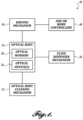
- FIGURE 1 is a functional block diagram of one example of a self-cleaning optical assembly, generally designated 20, formed in accordance with aspects of the claimed invention.
- the assembly 20 comprises an optical body 24, a driving mechanism 30, an optical body cleaning mechanism 32, a fluid dispensing mechanism 36, sometimes referred to herein as a fluid applicator, and one or more controllers 40.
- the optical body 24, such as a transparent plate, a cylinder, a spherical-like plate, or the like, protects at least one interiorly disposed optical device 26 from being damaged by the exterior environment in which it's deployed, and provides an optical window 28 through which light can pass in route to the optical device.
- the fluid dispensing mechanism 36 applies a layer or film of non-stick liquid onto at least the optical window 28 of a clean optical body 24.
- a cleaning cycle is initiated by the one or more controllers 40.
- the optical body cleaning mechanism 32 is used to clean at least the optical window 28, as the driving mechanism 30 moves the optical body 24 with respect to optical body cleaning mechanism 32 or vice versa.
- the optical body cleaning mechanism 32 quickly and easily removes the contaminants from the optical window 28 of the optical body 24 as the non-stick film has impeded the adhesion of the contaminants to the exterior surface thereof.
- the fluid dispensing mechanism 36 again applies a layer or film of the liquid onto the newly cleaned optical window of the optical body 32 and the optical body is returned to its first or home position.
- the fluid dispensing mechanism 36 also referred to as a fluid applicator, in the representative embodiments disclosed herein include an applicator body having a fluid chamber with any cross-sectional shape.
- an applicator body having a fluid chamber with any cross-sectional shape.
- the fluid chamber of the applicator body should be entirely filled with the liquid, although acceptable results are achieved with less than a filled fluid chamber.
- the applicator body also includes one or more outlets to facilitate recirculation, filtration or drainage of the liquid.
- the shape and the location of the outlet can be chosen such that small particles (if any) entering the fluid applicator over-time do not accumulate near the application side but instead exit through the outlet for optional filtration or accumulation away from the applicator.
- the fluid chamber can have any shape.
- the shape of the fluid chamber can be advantageously configured so that it discourages trapping of gasses to ensure a complete fill.
- An example of such a configuration includes the introduction of an angle in the interior upper surface of the fluid chamber to guide the gas bubbles to the inlet or the optional outlet and exteriorly of the applicator.
- the angle of installation of the optical assembly in service can be taken into account when designing the shape of the fluid applicator so that any spots within the fluid chamber that are close or in contact with the optical body are not starved out of fluid.
- the fluid applicator in the representative embodiments disclosed herein also includes an applicator element.
- the applicator element is in the form of a dynamic rod seal.
- the applicator element is in the form of a face seal or the like.
- the face or rod seals could be a type of an O-Ring, an internally lubricated O-Ring, an O-ring energize U-cup or lip seal, a metal spring energized U-cup or lip seal, or other commercially available types of sealing elements suitable for a dynamic face or rod seal configuration.
- An example of a dynamic rod seal are those sold by Parker Hannifin under the Standard PolyPak family of seals.
- U-cup face seals with and without energizing elements are those sold by Parker Hannifin under the FlexiSeal family of seals.
- the fluid applicator could include a fluid permeable media such as a media with nano-tubes or a porous elastomer.
- the face seal When assembled, the face seal is positively compressed between the optical body and the applicator body.
- the amount of compression can be controlled either by controlling the gap between the applicator and the optical body by, for example, adjusting a screw or machining tolerances, or by controlling the compression force by, for example, adjusting the compression of an associated spring.
- the optical body cleaning mechanism 32 in the representative embodiments disclosed herein includes a wiper or wiping element that exhibits a wiping or scrapping action for cleaning the optical window of the optical body 24.
- the wiper includes an edge which is in complete contact with, and preferably positively compressed against, the optical body.
- the amount of wiper compression can be controlled either by controlling the relative location of the wiper with respect to the optical body or by the amount of force applied, for example, via a spring or the like.
- the wiper can have a straight, angular, or a curved shape as long as the wiping edge is in complete contact with the optical surface with sufficient compression to ensure that the fouling matter does not cause temporary disengagement of the wiping edge.
- the wiper can be shaped such that it guides the collected fouling matter away from the optical body as a result of the relative movement between the optical body and the wiper. For example, in the case of a rotating optical surface, introducing an angle to the wiper edge with respect to the radius of the movement can have the effect of driving the fouling matter to the outer periphery of the optical surface.
- the length of the wiper it typically such that its projection perpendicular to the direction of movement (for a rotating surface, the radial direction) is equal to or slightly larger than the width of the surface effectively wetted by the fluid applicator. Furthermore, in some embodiments, the path of the wiper should be centered with respect to the path of the fluid applicator.
- a non-stick liquid can be defined as any liquid which possesses the following characteristics:
- Examples of a non-stick liquid that can be practiced with several embodiments disclosed herein include a range of hydraulic oils that are designed to demonstrate antiwear properties, resist foaming, release air, maintain relatively stable viscosity within the field temperature range, are suitable for filtration, and demonstrate low volatility and hydrolytic stability.
- An example of such hydraulic oil would be "All Weather Hydraulic 68" produced by Shell, Mobil, Chevron and other major manufacturers.
- Some hydraulic oils feature an anti-static electricity/anti-magnetic characteristic which may further aid in reducing dust attraction.
- An example of such oil would be Omega 612 by Omega Corporation.
- Some oils that can be used have hydrophobic characteristics which may help with quick repelling of water drops.
- An example of such oil would be DOT5, which is a silicon-based hydraulic oil.
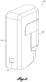
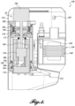
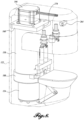
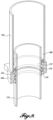
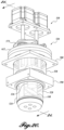
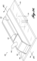
- FIGURES 2 and 3 illustrate a perspective view and cross-sectional view, respectively, of one representative embodiment of a self-cleaning optical assembly 120.
- the optical assembly 120 includes a housing 122 that protects the remaining components of the assembly.
- some of the components disposed within the housing 122 include an optical body 124, which is in the form of a cylinder ("optical cylinder 124") in this embodiment.
- the optical cylinder 124 is an optical grade substrate.
- the optical cylinder 124 is constructed out of a number of different materials, such as scratch resistant optically clear polycarbonate, optical acrylic, and different types of glass. Other materials such as germanium could also be used to construct the optical cylinder in the case the optical device is a thermal camera.
- the optical device 126 can include but is not limited to devices referred to in the art as electro-optical sensors, photoelectric sensors, image sensors, light sensors, cameras, optical emitters, optical detectors, etc.
- the optical device 126 includes a camera mounted inside a holding unit 146. As shown in FIGURE 3 , the camera is disposed longitudinally in the holding unit 146, which in turn, is installed longitudinally along the optical cylinder 124.
- the optical device 126 has a line of sight in the radial direction of the optical cylinder 124 via a 45 degree mirror 148 or other reflective medium, through a radial opening 150 in the holding unit 146 and a transparent wall portion of the optical cylinder 124, referred to as the optical window 128.
- the meaning of the word "transparent” as used herein expands beyond the visible light spectrum and conveys transparency to any particular wavelength used by the optical device, whether or not the material is transparent to human vision.
- the optical window 128 is aligned with an opening 152 ( FIGURE 1 ) in the housing 122 when the optical cylinder 124 is in its home position of FIGURE 3 .
- heating elements are mounted above and below the radial opening 150. The heating elements are configured and arranged to help eliminate condensation in front of the camera by heating the optical cylinder.
- the optical device 126 is shown as having an optical axis parallel to a longitudinal axis of the housing 122, although other configuration are within the scope of the present invention as defined by the claims.
- the optical device 126 can be mounted radially (as opposed to axially), thereby eliminating the need for the mirror 148.
- the optical device and associated mirror are stationarily mounted within the optical cylinder.
- the mirror can move in a tilting motion while the optical assembly can rotate about the center of the optical cylinder.
- the mirror can both tilt and rotate, while the rest of optical assembly remains stationary.
- the optical assembly can be used as a scanning device.
- the mirror and a detector associated with the mirror rotate about the center axis of the optical cylinder.
- either the optical assembly and/or the optical device can be configured to rotate, if desired.
- the optical cylinder 124 When assembled, the optical cylinder 124 is movable with respect to, and in one embodiment within, a portion of, a fluid cylinder 158 via the driving mechanism 30.
- the driving mechanism 30 in one embodiment is a linear actuator composed of, for example, a lead screw 164 that is turned by an electric motor 166, such as a stepper motor.
- a stepper motor with an integrated lead screw as the motor shaft is employed.
- the motor 166 is supported by a cap 168, which seals one end of the fluid cylinder 158 with the aid of a suitable sealing means, such as an O-ring, heat bonding, chemical bonding, etc.
- the lead screw 164 extends inwardly into the fluid cylinder 158 in a coaxial manner.
- An optional sensor 160 may be provided to detect the end of the lead screw.
- the output of the sensor 160 is used by at least one of the one or more controllers 40 as a positional reference when actuating the optical cylinder 124.
- a lead screw nut 170 Engaged with the lead screw 164 is a lead screw nut 170.
- the lead screw nut 170 is rotationally fixed to a piston 172, which is securely mounted to the end of the optical cylinder 124.
- rotation of the lead screw 164 in both clockwise and counterclockwise directions via the electric motor 166 causes the lead screw nut 170, and in turn, the optical cylinder 124 to reciprocate within the fluid cylinder 158 between the positions shown, for example, in FIGURES 3 and 4 .
- the electric motor 166 can be controlled via suitable drive signals in order to move the optical cylinder 124 through one complete cycle (i.e., first or home position of FIGURE 3 , retracted position of FIGURE 4 , first or home position of FIGURE 3 ).
- the driving mechanism 30 in the embodiment shown imparts movement to the optical cylinder
- the driving mechanism 30 can be configured to impart movement to the fluid cylinder 158 instead.
- the lead screw nut 170 is connected to the piston 172 via a flexible coupling 174, as shown in FIGURE 6 .
- the flexible coupling 174 is formed by an elastomeric washer 176 or the like positioned on both sides of the piston 172 and squeezed between the lead screw nut 170 and a plate 180. The amount of squeeze on the elastomer is controlled through the choice of the length of fasteners, for example, shoulder bolts, and the thickness of the elastomer. Accordingly, the flexible coupling 174 is configured to compensate for any angular misalignments or out-of-centeredness of the lead screw 164 with respect to the piston 172.
- the linear actuator is shown in one representative embodiment as a lead screw mechanism, other types of linear actuators may be practiced with embodiments of the claimed invention.
- the linear actuator can be of the rack and pinion type, a pneumatic or hydraulic cylinder, a pulley/cable arrangement, a linear motor, etc.
- the drive mechanism includes an electric motor and gear arrangement, a linear actuator and a linear to rotational reciprocating mechanism, such as a scotch yoke, crank, etc., or any other currently known or future developed mechanism that can impart a rotationally reciprocating movement to the optical cylinder.
- the optical cylinder can be rotated directly or indirectly via the rotary output shaft of a suitable stepper or servo motor.
- the piston 172 is configured to form a liquid tight seal against the inner wall of the fluid cylinder 158.
- the seal is created with a X-Ring (i.e., an O-ring with a cross section resembling an "X").
- the X-ring is employed in some embodiments in order to reduce friction between the piston and the fluid cylinder as compared to some other seal types, although any other piston seal can be utilized.
- a first sealed fluid chamber 184 is formed within the walls of the fluid cylinder between the sealed end of the fluid cylinder 160 and the piston 172.
- the lead screw 164 and the lead screw nut 170 are disposed within an optional impermeable bellows 186.
- the bellows 186 at one end is sealed against the piston 172 and at the other end is sealed against the cap 168.
- the first fluid chamber 184 is formed between the walls of the fluid cylinder 158 and the bellows 186.
- a gland 188 is sealably mounted to the end of the fluid cylinder 158 opposite the cap 168.
- the gland 188 surrounds the optical cylinder 124 and allows the optical cylinder 124 to reciprocate therethrough.
- the gland 188 defines an inner bore 200 through which the optical cylinder 124 reciprocally moves.
- the inner bore 200 is configured such that an inner bore surface supports the outer surface of the optical cylinder 124 in a guiding manner as it moves therethrough.
- the inner bore 200 is sized and configured such that the inner bore surface bears against the outer surface of the optical cylinder 30 so as to form a linear bearing.
- the optical cylinder 124, the fluid cylinder 158, the piston 172 and the gland 188 cooperate to define a second fluid chamber 208, as shown in FIGURES 3 and 4 .
- the second fluid chamber 208 is formed between the gland end of the fluid cylinder 158 and the piston 172, and between the outer surface of the optical cylinder 124 and the inner surface of the fluid cylinder 158.
- the second fluid chamber forms a part of a fluid applicator or dispensing mechanism 36.
- a stabilizing linkage 212 is provided. , one end of the stabilizing linkage 212 is anchored to the gland 188 while the opposite end is connected to an optical cylinder end cap 214. Accordingly, in these embodiments, the stabilizing linkage 212 prevents rotation of the optical cylinder 124, which in turn, prevents rotation of the lead screw nut 170. It will be appreciated that other mechanisms or configurations of the optical cylinder/gland can be employed to provide rotation prevention of the optical cylinder 124.
- the gland 188 includes a primary seal 216 configured and arranged to seal the second fluid chamber 208.
- the sealing action occurs between the exterior surface of the optical cylinder 124 and the inner bore surface of the gland 188.
- the primary seal is compressed between the exterior surface of the optical cylinder 124 and the inner bore surface of the gland 188.
- the primary seal 216 exerts pressure against the outer surface of the optical cylinder 124.
- the piston seal can be omitted such that the first and second fluid chambers 184 and 208 together form a single fluid reservoir.
- the second fluid chamber 208 stores a quantity of non-stick liquid.
- the second fluid chamber 208 stores enough liquid for a plurality (e.g., 2 or more, 5 or more, 10 or more, 20 or more, 50 or more, etc. ) of cleaning cycles.
- the primary seal 216 seals the second fluid chamber 208
- the primary seal also helps to apply or maintain a thin (e.g., a few microns) layer of liquid on the optical cylinder 124.
- a thin e.g., a few microns
- the primary seal 200 aids in the formation of a thin layer of non-stick liquid that remains on the optical window 128 as the optical cylinder 124 returns to its home position.
- the second fluid chamber 208 and the primary seal 216 together form one embodiment of the fluid dispensing mechanism 36. It will be appreciated that the size and/or compression of the primary seal 216 can be used in controlling the thickness of the liquid layer.
- the gland 188 further includes a secondary seal 218 disposed between the exterior surface of the optical cylinder 124 and the inner bore surface of the gland 188.
- the secondary seal 208 is positioned closer to the free end of the optical cylinder 124 than the primary seal 200 (e.g., positioned exteriorly of the primary seal 216).
- the secondary seal 218 is configured with a sharp edge and tapers at an acute angle inwardly toward the outer surface of the optical cylinder 124 in some embodiments.
- the secondary seal 218 is further configured and arranged such that its outermost edge is flush against and exerts a positive pressure against the outer surface of optical cylinder 124.
- the secondary seal 218 is configured to scrape or wipe away contaminants rather than to seal fluids, and therefore, can also be referred to herein as a wiping element or wiper ("wiper 218") or at least a part of one embodiment of the optical body cleaning mechanism 32.
- the wiper 218 is fabricated out of an elastomer having a hardness value similar to the primary seal 216.
- the wiper 218 is fabricated out of an elastomer having a hardness value greater than the primary seal 216.
- the wiper 218 has a Shore A hardness in the range of about 85-95. It should also be appreciated that the material chosen for the wiper 218 should be chemically compatible with the non-stick liquid and vice versa.
- a non-sealing piston may be used.
- a non-sealing piston can still utilize a flexible seal but also includes channels to allow flow of fluid between the first and second fluid chambers Such a piston would still provide damping, self-centering characteristics and support but would reduce the amount of actuation force needed to move the optical cylinder.
- the primary seal 216 and secondary seal 218 are integrally formed.
- the seal body includes two lips that serve the functions of the primary seal and wiper described above.
- the second fluid chamber 208 defines a fluid reservoir for dispensing a non-stick liquid onto the outer surface of the optical window of the optical cylinder 124.
- the second fluid chamber 208 is a discrete, stand-alone fluid reservoir.
- the fluid reservoir can be replenished via either a local fluid source, such as a fluid cartridge 236, or a remote fluid source, via appropriately arranged fluid lines, passages, connectors, etc.
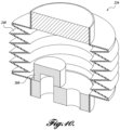
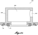
- FIGURE 10 illustrates one embodiment of an optional fluid cartridge 236 that can be practiced with embodiments of the claimed invention for supplying non-stick liquid to the fluid reservoir (e.g., the second fluid chamber 208 or the combined space of first and second fluid chambers 184 and 208).
- the fluid cartridge 236 includes an enclosure 238 that houses a fluid reservoir formed by a sealed expandable bellows 240.
- the fluid cartridge 236 includes a rigid liquid storage tank and a breather vent that functions to avoid pressure drop as the liquid is used up as well as to neutralize any pressure change due to volume differences between first and second chambers 184 and 208 during an extension and retraction cycle.
- first and second press-to-connect fluid fittings 242 and 244 are mounted to the fluid cartridge 236 and are configured to cooperate with corresponding fittings within the housing 122.
- the fluid cartridge 236 in some embodiments also includes an optional filter 260 for filtering any non-stick liquid returned to the fluid cartridge, as will be described in more detail below.
- the fluid cartridge 236 and the housing 122 are cooperatively configured so that the fluid cartridge 236 is removably mounted in the housing 122, as shown in FIGURES 1-3 . Accordingly, once the liquid in the fluid cartridge is depleted, the fluid cartridge 236 can be replaced.
- the level of liquid inside the fluid cartridge 236 is monitored so as to provide a fluid cartridge replacement notification function to the optical assembly 20.
- the level of liquid in the fluid cartridge can be indirectly measured by an optical proximity sensor 264, as shown in FIGURE 3 .
- the proximity sensor 264 is configured to measure the height of the bellows 240 and transmit such measurement to the one or more controllers 40.
- the controller 240 outputs an alert to the user, via an electric signal transmitted to a central monitoring station, activating a visual indicator, such as an LED or the like, among others.
- the at least one port 232 includes two ports disposed in the gland 188.
- the gland 188 includes suitable connection interfaces that are in fluid communication with the ports 232, as shown in FIGURE 8 .
- the connection interfaces provide a simple interface for connection with fluid conduits, piping, hose or the like, that form one or more fluid lines.
- the fluid lines can be connected to the on-board or local fluid source, such as the fluid cartridge 236, and/or with a remotely located fluid source in a conventional manner.
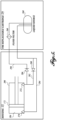
- FIGURE 5 is a schematic diagram of a fluid circuit.
- the fluid circuit can be employed by embodiments of the optical assembly 20.
- the second fluid chamber 208 in one embodiment is connected in fluid communication with a source 268 of non-stick liquid, via the ports 232.
- the first fluid chamber 184 in one embodiment is connected in fluid communication with the liquid source 268.
- access to the first fluid chamber 184 is provided by a port 270 (see also FIGURE 3 and 8 ).
- the port 270 is disposed in the cap 168.
- a suitable fluid fitting can be used to provide a simple interface for connection with fluid conduits, piping, hose or the like, that form one or more fluid lines.
- the first fluid chamber 184 is connected to the source 268 of non-stick liquid via fluid line 284.
- the second fluid chamber 208 is connected in fluid communication to the liquid source 268 through check valves 286 and 288 and fluid lines 290 and 292, respectively.
- the fluid line 292 is connected in fluid communication with fluid line 284, and in turn, the liquid source 268.
- the check valve 286 is associated with fluid line 290 and is configured to allow fluid flow from the second fluid chamber 208 to the liquid source 268 but prevents reverse fluid flow from the liquid source 268 to the second fluid chamber 208.
- Check valve 288 is configured to allow fluid flow via lines 284, 292 to the second fluid chamber 208 from the liquid source 268 but prevents fluid flow from the second fluid chamber 208 to the liquid source 268.
- an optional filter 260 is placed in-line with fluid line 290 between the check valve 286 and the liquid source 268.
- the optional filter 246 can be used if needed, such as in situations where the contamination particle size approaches the surface roughness of the optical cylinder.
- the filter 246 is incorporated therein.
- the optical assembly operates in its environment with the optical cylinder 124 in the extended state, as shown in FIGURE 3 .
- the optical cylinder 124 is actuated through a cleaning cycle under the control of the one or more controllers 40.
- the cleaning cycle includes two stages, for example.
- the one or more controllers 40 are shown as being located “on-board” the optical assembly 20, it will be appreciated that at least one of the one or more controllers 40 can be located “off-board” in a remote location.
- an "on-board” controller is configured to receive control and other signals from an "off-board” controller.
- the one or more controllers 40 are connected in electrical communication with the driving mechanism 30 and one or more sensors, such as sensor 160, optical proximity sensor 264 and/or dirt/debris sensor 300.
- the one or more controllers 40 include logic for controlling the movement of the optical cylinder 124. It will be appreciated by one skilled in the art that the logic may be implemented in a variety of configurations, including but not limited to, hardware, software, and combinations thereof.
- the controller 36 includes a processor and memory.
- the memory can be any volatile and nonvolatile storage media in the form of read-only memory (ROM), random-access memory (RAM), and keep-alive memory (KAM), for example.
- the computer-readable storage media may be implemented using any of a number of known memory devices such as PROMs (programmable read-only memory), EPROMs (electrically PROM), EEPROMs (electrically erasable PROM), flash memory, or any other electric, magnetic, optical, or combination memory devices capable of storing data.
- the data includes executable instructions, used by processor, in controlling the operation of at least the driving mechanism 30.
- processor is not limited to integrated circuits referred to in the art as a computer, but broadly refers to a microcontroller, a microcomputer, a microprocessor, a programmable logic controller, an application specific integrated circuit, other programmable circuits, combinations of the above, among others.
- the processor executes instructions stored in memory to provide suitable control signals to the driving mechanism, etc.
- the preselected time is chosen and programmed into the one or more controllers 40 based on the "dry out” period of the liquid employed as the liquid.
- the "dry out” period depends in part on the vapor pressure of the fluid, ambient temperature, as well as the severity of the convection that the exposed part of the optical cylinder is subject to.
- the preselected time is chosen in one embodiment to be less than the time it takes for the liquid film on the optical cylinder to dry out or evaporate.
- the first stage of the cleaning cycle includes movement of the optical cylinder 124 in a first direction with respect to the fluid cylinder 158.
- the linear actuator such as the lead screw 164, is controlled by suitable signals from the one or more controllers 40 in order to retract the optical cylinder 124 from its first or home position shown in FIGURE 3 to a retracted position shown in FIGURE 4 .
- any contaminants present on the optical cylinder 124 are pushed or wiped downwardly relative to the optical cylinder 124 by the wiper 218 and removed therefrom.
- the contaminants fall away (due to gravity) from the optical cylinder 124 through an open bottom of the housing 22 when sufficient accumulation of the contaminants occurs.
- the wiper 218 cleans the outside surface of the optical cylinder 124, including the optical window 128.
- the optical cylinder can further include a cap that seals its free end.
- the cap is cone shaped so as to facilitate guiding of the liquid towards the ground.
- the piston 172 which moves with the optical cylinder 124, forces any non-stick liquid present in the first fluid chamber 184 out through port 270 and back into the liquid source 268 via the fluid line 284.
- non-stick liquid is drawn into the second fluid chamber 208 only through fluid line 292 due to the operation of the check valves 286 and 288.
- check valve 286 prevents liquid flow through the filter 260 and fluid line 290 while check valve 288 allows fluid to flow in the direction from the fluid reservoir to the second fluid chamber 208. This results in fluid flow through the filter 260 in only one direction. As such, the recirculation of any particles contained by the filter is prevented.
- the exterior of the optical cylinder 124 is immersed in the non-stick liquid.
- the second stage includes movement of the optical cylinder 124 in a second direction opposite the first direction to return the optical cylinder 124 to its first or home position.
- the linear actuator such as the lead screw 164
- the linear actuator is controlled by suitable signals transmitted from the one or more controllers 40 in order to extend the optical cylinder 124 from the second or retracted position shown in FIGURE 4 to the first or home position shown in FIGURE 3 .
- a fresh layer of non-stick liquid adheres to and coats the exterior of the optical cylinder, including the optical window 128.
- the thickness of the fluid layer depends on a variety of factors such as the surface roughness of the optical cylinder, roughness of the primary seal, the hardness of the primary seal, the amount of squeeze applied on the primary seal and the relative speed of movement of the optical cylinder, among other factors.
- Extension of the optical cylinder 124 also causes the first fluid chamber 184 to fill with fluid from the liquid source, such as the fluid cartridge 236, through line 284 and port 270. Liquid fills the first fluid chamber 184 as the pressure drops in the first fluid chamber184 due to the suction action of the piston 172. Simultaneously, the fluid in the second fluid chamber 208 is pushed out through the ports 232, through lines 290 and 292 to check valves 286 and 288. Only check valve 286 allows the fluid to pass, which then continues to flow through the option filter 260 and into the liquid source, such as the fluid cartridge 236. On the other hand, check valve 288 blocks further flow of fluid through fluid line 292.
- the cleaning cycle can be initiated either by a preselected elapse of time, a signal indicative of a dirty optical window, etc.
- the optical device is a camera
- the camera image itself could be used to detect smudge/dirt or to detect rain drops affecting the image.
- the signal is generated by a dirt/debris detection sensor.
- FIGURES 12-13 illustrate one embodiment of a dirt/debris detection sensor 300 that can be practiced with embodiments of the claimed invention.
- the sensor 300 measures and/or detects the state of clarity of the optical cylinder.
- the sensor 300 includes an emitter 304 and a detector 308.
- the sensor 300 includes a single frequency emitter such as a laser and a narrow bandwidth detector suitable for detecting the wavelength produced by the emitter.
- the emitter 304 and the detector 308 can be mounted in the holding unit 146, as shown in FIGURE 13 . It will be appreciated that the closer the emitter and the detector are to the opening 150, the more relevant the sensing will be to the cleanliness of the view of the optical device.
- FIGURE 13 shows a cross section of the optical cylinder where the emitter 304 and the detector 308 are installed.
- the angle of the emitter 304 is less than the critical refraction angle of the optical cylinder 124 such that the ray of light 310 after refracting in the optical cylinder exits to the environment without refracting back in.
- the emitter 304 is positioned such that the exit point314 of the ray of light 310 on the exterior of the optical cylinder 124 is positioned right in front of the detector 308.
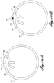
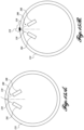
- the detector 308 in another embodiment can be placed such that it creates the same angle with respect to the radius of the circle as the emitter 304, as shown in FIGURES 15A-15B .
- the optical cylinder 124 is clean, the ray of light 310 exits to the environment without affecting the detector 308, as shown in FIGURE 14 .
- the ray of light 310 reflects back in various directions at the point of the incident, as shown in FIGURE 15 .
- the emitter 304 in order to distinguish whether the detected light at the detector 308 is coming from the sun or from the emitter 304, the emitter 304 is periodically pulsed several times a second by the one or more of the controllers 40. In one embodiment, the one or more controllers 40 compare the output of the detector 308 when the emitter 304 is on against the times that the emitter 304 is off. If the difference is consistently larger than a certain threshold, such difference indicates that the optical cylinder is blocked by an object. This analysis in one embodiment is done on-board by at least one of the one or more controllers 40. The results can also be communicated to a remote system.
- the senor when the detector is directly facing the sunlight, the sensor can become saturated. To address any possible saturation, any combination of the following solutions can be implemented.
- filtering and attenuating the incoming light to the sensor can be implemented to generate a sufficient margin before saturating the detector. Doing so would also attenuate the light emitted by the emitter. Consequently, the power of the emitter can be adjusted accordingly to generate an adequate change in the detection value upon its operation.
- the wavelength of the emitter and the detector can be chosen to fall within the atmospheric absorption bands where the intensity of the wavelength of choice has been significantly attenuated due to atmospheric elements. In this case, saturation of the detector is less of a concern.
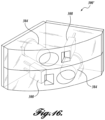
- a sensor 300' can be employed, having a pair of emitters and a pair of detectors, as shown in FIGURE 16 .
- the detectors 308 can be arranged such that their orientation is such that when one detector is facing the sun, the other detector would be looking away from the sun.
- Such a design prevents simultaneous saturation of all detectors.
- the output of all sensors are read and analyzed by the one or more controllers 40.
- the output of the detector which is determined to be saturated will be omitted.
- the detectors 308 are each shown as a rectangular transducer, both of which are pointing at very different angles than each other ensuring that they do not saturate simultaneously due to the same light source.
- the curved surface of the sensor faces exteriorly and matches in some embodiments with the curvature of the inside of the optical body. Placement of the sensor300' in complete contact with the optical body minimizes the amount of light leaking from the emitters 304 to the detectors 308.
- the emitters 304 transmit at about a 940 nm wavelength.
- an optical assembly can be employed in various devices, systems, and assemblies. Additionally, the techniques and methodologies described above can be employed in other configurations of the optical assembly. For example, in some applications, having a pair of optical devices is beneficial or advantageous. An example of such application is a stereo camera which enables calculation of depth information in addition to the camera view. This example can be implemented in many different configurations.
- an optical assembly according to another embodiment integrates two optical devices into one longer optical cylinder. In this embodiment, one of the optical devices is positioned at each end of the cylinder and a piston is attached to the middle of the optical cylinder. Other configurations are possible, as will be described in more detail below.
- an optical assembly is formed generally by placing the working components of two optical assemblies 20 back-to-back.
- two separate optical cylinders each attached to a liquid tight piston are employed.
- each optical cylinder shares the same fluid cylinder.
- the wiping action to clean the optical cylinders would involve extension and retraction of each individual optical cylinder. In the fully retracted mode the two pistons are closest to each other while in the extension configuration the two pistons are the farthest from each other.
- optical devices such as stereo cameras
- the optical devices are fixed with respect to each other in order to keep their calibration. Even slight positional variations between the cameras from one cycle to the other could be detrimental to the performance of the stereo camera pair.
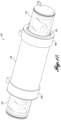
- FIGURE 17 illustrates another embodiment of an optical assembly 420 formed in accordance with an aspect of the claimed invention where the optical devices are fixed with respect to one another.
- the optical assembly 420 is substantially similar in construction and operation as the optical assembly 20 described above except for the differences that will be explain in more detail below.
- the optical assembly 420 includes two optical cylinders that are joined by a piston 172 at the middle and are enclosed in the same fluid cylinder 158. As such, relative movement of the two joined optical cylinders with respect to the fluid cylinder creates the wiping action.
- two support arms 440 and 442 are attached to the piston 172 at the center, while the other ends of the support arms are attached to the end caps 214.
- the connections between the support arms, the piston and the end caps are rigid.
- an optical cylinder 124 is axially sandwiched between the end cap 214 and the piston 172.
- a flexible gasket creates the interface between the optical cylinder and the end caps. The amount of squeeze in the gasket can be adjusted though choosing the length of the support arm, the length of the optical cylinder, and the thickness of the gasket.
- the optical cylinder is radially constrained by the O-Ring seals at each end. The O-ring seals also create a liquid tight seal at each end of the optical cylinder.
- the optical devices 126 are mounted directly onto the support arms 440 and 442. Such an arrangement ensures rigid positioning of the two optical devices with respect to each other. Additionally, since the optical cylinders 124 are supported by all non-rigid connections, they are isolated from any bending loads caused by the dynamic forces in service. The aforementioned loads are transferred through the rigid connections of the support arms.
- the cleaning cycle for this embodiment involves the relative movement of the optical cylinder assembly with respect to the fluid cylinder 158. During such movement the liquid tight piston 172 causes fluid flow in and out of the respective ports. This flow can be used in very much the same way as explained in the fluid circuit of FIGURE 5 . However, two additional check valves can be used in this embodiment, and arrangement as shown in fluid circuit 500 of FIGURE 19 .
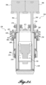
- FIGURE 20 illustrates another embodiment of an optical assembly 520 formed in accordance with an aspect of the claimed invention.
- the optical assembly 520 is substantially similar in construction and operation as the optical assembly 120 described above except for the differences that will be explain in more detail below.
- the optical assembly 520 includes a driving mechanism 530 in the form of dual lead screws that provide reciprocating motion to an optical cylinder 524 with respect to an outer fluid cylinder 558.
- the optical device 126 Disposed within or otherwise protected by the optical cylinder 524 is at least one optical device 126.
- the optical device 126 has a line of sight in the radial direction of the optical cylinder 524 via a 45 degree mirror 148 or other reflective medium, through an optical window 128.
- the optical window 128 can be aligned with an opening of an optional housing (not shown) when the optical cylinder 524 is in its home position of FIGURES 20 and 21 .
- a first optical cylinder end cap 568 seals one end of the optical cylinder 524 with the aid of a suitable sealing means, such as an O-ring, heat bonding, chemical bonding, etc.
- a second, tapered end optical cylinder end cap seals the other end of the optical cylinder 524 with the aid of a suitable sealing means, such as an O-ring, heat bonding, chemical bonding, etc.
- the first and second end caps are fixed to a support arm assembly.
- flexible gaskets sandwiched between the end caps and the optical cylinder can provide damping and thermal strain relief, if desired.
- the lead screws 564 extend inwardly into the optical cylinder 524 on the sides thereof.
- Optional sensors may be provided to detect the ends of the lead screws.
- the output of the sensors is used by at least one of the one or more controllers 40 as a positional reference when actuating the optical cylinder 524.
- full retraction of the lead screws can be sensed by optional sensors fixed to the motor mounting plate.
- Engaged with the lead screws 564 are lead screw nuts 570.
- the lead screw nuts 570 are rotationally fixed to a mounting bracket 572, which is attached to the optical cylinder end cap 568 via a flexible coupling.
- the optical cylinder 524 reciprocates within the fluid cylinder 558.
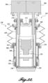
- upper and lower glands 588 and 590 are sealably mounted to the ends of the fluid cylinder 558.
- Each gland 588 and 590 surrounds the optical cylinder 524 and allows the optical cylinder 524 to reciprocate therethrough.
- the glands 588 and 590 define inner bores through which the optical cylinder 524 reciprocally moves in a guiding manner.
- the fluid chamber 608 is formed between the outer surface of the optical cylinder 524 and the inner surface of the fluid cylinder 558.
- the lower gland 590 includes an inlet (not shown in FIGURES21-22 ) for accessing the fluid chamber 608.
- the upper and lower glands 588 and 590 each include a primary seal 216 configured and arranged to seal the fluid chamber 608.
- the sealing action occurs between the exterior surface of the optical cylinder 524 and the inner bore surface of the glands 588, 590.
- the primary seal 216 is compressed between the exterior surface of the optical cylinder 524 and the inner bore surface of the glands 588, 590.
- the primary seals 216 can have different configurations.
- the lower primary seal may be configured for its fluid film application properties while the upper primary seal may be configured for its low friction in reciprocating motion.
- the fluid chamber 608 stores a quantity of non-stick liquid. While the lower primary seal 216 seals the fluid chamber 608, the lower primary seal 216 also aids in the application or maintenance of a layer of fluid covering at least the optical window 528.
- the optical cylinder 524 is reciprocally moved with respect to the fluid cylinder 558, at least the optical window of the optical cylinder 524 comes into fluid contact with the liquid disposed therein.
- the lower primary seal 216 aids in the formation of a thin layer of non-stick liquid that remains on the optical window as the optical cylinder 524 returns to its home position of FIGURES 20 and 21 .
- at least the fluid chamber 608 and the lower primary seal 216 together form an embodiment of the fluid dispensing mechanism 36.
- the lower gland 590 further includes a secondary seal 218 disposed between the exterior surface of the optical cylinder 524 and the inner bore surface of the gland 590.
- the secondary seal 218 is positioned closer to the free end of the optical cylinder 524 than the primary seal 216.
- the secondary seal 218 is again configured with a sharp edge and tapers at an acute angle inwardly toward the optical cylinder 524 in some embodiments.
- the secondary seal 218 is further configured and arranged such that its outermost edge is flush against and exerts a positive pressure against the optical cylinder 524.
- the secondary seal 218 is configured to scrape and/or wipe away contaminants rather than to seal fluids, and therefore, can also be referred to herein as a wiping element or wiper ("wiper 218").
- the wiper 218 also forms an embodiment of the optical body cleaning mechanism 32.
- the fluid chamber 608 can be connected to an internal cavity 610 formed by an optional impermeable bellows 612.
- the bellows 612 at one end is sealed against upper gland 588 and at the other end is sealed against the cap 568.
- This arrangement allows for extension and compression of the bellows 512 upon movement of the optical cylinder 524 with respect to the fluid chamber 608 and vice versa.
- the upper gland 588 is formed with multiple channels 614, which are configured to allow fluid to flow between the internal cavity 610 of the bellows 612 and the fluid chamber 608.
- channels 614 are omitted in embodiments without the bellows 612.
- the bottom gland 590 in this and other embodiments is connected to a fluid bladder 656 via an inlet 662, as shown in the fluid circuit of FIGURE 23 .
- the fluid bladder 656, or other fluid reservoir stores excess fluid, and if desired, is connected to the inlet 662 through an optional filter medium as well as one or more directional valves (e.g., umbrella valves, check valves, etc.).
- the bellows 612 expands causing the pressure to decrease within the internal cavity 610 and fluid chamber 608 and the liquid to be drawn into the fluid chamber 608 from the fluid bladder 656.
- the bellows 612 compresses causing the pressure to increase in the internal cavity 610 and fluid chamber 608 and the fluid to be pumped from the fluid chamber 608 into the bladder 656 through the optional filter via the inlet 662. It will be appreciated that the addition of the bellows 612 and the fluid bladder 656 demands less actuation force than embodiments with a liquid tight piston, enabling faster cleaning cycles in a smaller or similar package.
- this design provides flow of fluid around the primary seal 216, which provides two distinct benefits: (1) it prevents fluid starvation of the primary seal even when the device is used in odd orientations; (2) it agitates any contamination which may have precipitated on the primary seal. This ensures that during the action of filtering, the contaminants are floating and are pumped through the filtering medium.
- the connection of the bellows to the optical cylinder end cap can be eliminated.
- the bellows can instead be complemented with another smaller-diameter internal bellows.
- the two bellows would be sealed at the top, while at the bottom they would be connected to the top primary seal gland, with the fluid channels lying in-between them.
- An internal compression spring can erect the two connected bellows.
- the optical cylinder end cap pushes and compresses this collapsible tank pumping the liquid out, while during retraction the internal compression spring will re-erect the two bellows, thereby drawing the liquid back in.
- the stroke for pumping can be smaller than the cleaning action stroke.
- an optical assembly according to another embodiment integrates two optical devices, such as optical assemblies 520, into one longer optical cylinder.
- the two bellows can be replaced with a shared or two connected bellows.
- the fluid ports can be chosen to be in the bellow(s) or embedded in either of the glands.
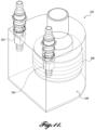
- FIGURES 24 and 25 illustrate another embodiment of an optical assembly 720 formed in accordance with an aspect of the claimed invention.
- FIGURE 24 is a perspective view of the optical assembly 720.
- FIGURE 25 is a cross section view of the optical assembly 720 of FIGURE 24 .
- the optical assembly 720 includes an optical body 724, a fluid applicator 736, and an optical body cleaning mechanism 732.
- the optical body 724 is formed as an optical cylinder that houses one or more optical devices 126 therein.
- the optical cylinder 724 is rotated by a suitably configured and arranged drive mechanism (not shown) about a central axis A so that the optical window is moved with respect to both the fluid applicator 736 and an optical body cleaning mechanism 732.
- Rotation in some embodiments can be in only a single direction, while rotation in other embodiments includes reciprocating rotation or angular oscillation.
- the fluid applicator 736 in this embodiment includes an open ended housing 738.
- the housing 738 includes a fluid chamber 740 in fluid communication with an opening defined by the housing 738.
- the open end of the housing 738 is configured to be flush against the optical body 724 and includes a groove disposed around the perimeter of the opening. The groove is configured to receive the primary seal 216.
- An optional inlet 742 is provided in the housing 738 for accessing the fluid chamber 740.
- the optical body cleaning mechanism 732 is again formed as a wiper, which is configured with a sharp edge and tapers at an acute angle inwardly toward the outer surface of the optical cylinder 724.
- the wiper is further configured and arranged such that its outermost edge is flush against and exerts a positive pressure against the outer surface of optical cylinder 724.
- the wiper is fabricated out of an elastomer having a hardness value similar to the primary seal 216.
- the wiper is fabricated out of an elastomer having a hardness value greater than the primary seal 216.
- the wiper has a Shore A hardness in the range of about 85-95.
- the wiper does not enclose the fluid applicator, and as such, it is possible for contaminants to enter the space between the wiper and the fluid applicator, bypassing the wiper and coming into contact with the fluid applicator.
- the space between the wiper and the fluid applicator may be optionally enclosed, and completely sealed in some embodiments.
- the optical assembly 720 includes an optional enclosure 744.
- the wiper is mounted to the enclosure 744, which is configured to also act as a scraper of foreign material.
- partial or fully circular seal plates 746 are provided between the enclosure 744 and the optical body 724.
- first and second seal plates 746 are disposed on each side of the wiper.
- the first and second seal plates 746 are fixed to the optical body724.
- fixation can be accomplished through adhesives, one or more O-rings, etc.
- the interface between the seal plates 746 and the enclosure 744 can be that of between two rigid materials similar to the one found in a bushing.
- the material of the enclosure as well as the seal plates can be chosen to result in a low friction interface.
- first and second seal plates 746 are fixed to the enclosure 744.
- the interface between the seal plates 746 and the optical cylinder 724 behave similar to a rotary seal.
- suitable seals used for rotary dynamic sealing such as shaft oil seals and bearing isolators, can be employed.
- Some examples of such seals are "FlexiCase TM CEE", “FlexiSeal FF", and “FlexiLip Rotary” by Parker Hannifin Corp.
- each seal plate can consist of two interleaving plates, namely outer and inner seal plates.
- the outer plate is fixed to the enclosure 744 and the inner plate fixed to the optical body 724.
- labyrinth-style seal geometries such as those used as bearing isolators would also be effective in these embodiments. Examples that may be practiced with embodiments are offered by Parker family of ProTech TM bearing isolators.
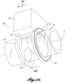
- FIGURES 26 and 27 illustrate another embodiment of an optical assembly 820 formed in accordance with an aspect of the claimed invention.
- FIGURE 26 is a perspective view of the optical assembly 820.
- FIGURE 27 is a cross section view of the optical assembly 820 of FIGURE 26 .
- the optical assembly 820 is substantially identical to the optical assembly 720 in construction and operation except for the differences that will now be described.
- the optical assembly 820 includes an optical body 824, a fluid applicator 836, and an optical body cleaning mechanism 832.
- the optical body 824 is formed as an optical plate having a planar optical surface.
- the optical body protects one or more optical devices 126.
- the optical plate is linearly reciprocated by a suitably configured and arranged drive mechanism (not shown) so that the optical window 828 is moved with respect to both the fluid applicator 836 and an optical body cleaning mechanism 832.
- the fluid applicator 836 in this embodiment also includes an open ended housing 838.
- the housing 838 includes a fluid chamber 840 in fluid communication with an opening defined by the housing 838.
- the open end of the housing is configured to be flush against the optical body 824 and includes a groove disposed around the perimeter of the opening that is configured to receive the primary seal 216.
- An optional inlet 842 is provided in the housing 838 for accessing the fluid chamber 840.
- the optical body cleaning mechanism 832 is again formed as a wiper or scraper, which is configured with a sharp edge and tapers at an acute angle inwardly toward the outer surface of the optical cylinder 824.
- the wiper is further configured and arranged such that its outermost edge is flush against and exerts a positive pressure against the outer surface of optical cylinder 824.
- the optical assembly 820 also includes an optional enclosure 844.
- the wiper is mounted to the enclosure 844.
- parallely extending seal plates 846 are provided on each side of the wiper between the enclosure 844 and the optical body 824. At the end of each seal plate 844 there is provided a lip-type seal for interfacing with the optical body 824. It will be appreciated that labyrinth-style seal geometries would also be effective in these embodiments.
- FIGURES 28-30 illustrate another embodiment of an optical assembly 920 formed in accordance with an aspect of the claimed invention.
- FIGURE 28 is a perspective view of the optical assembly 920.
- FIGURE 29 is a top view of the optical assembly of FIGURE 28 .
- FIGURE 30 is a cross section view of the optical assembly 920 of FIGURE 29 .
- the optical assembly 920 is substantially identical to the optical assemblies 720 and 820 in construction and operation except for the differences that will now be described.
- the optical assembly 820 includes an optical body 924, a fluid applicator 936, and an optical body cleaning mechanism 932.
- the optical body 924 is formed as an optical disc plate having a planar optical surface.
- the optical body shields or protects one or more optical devices 126.
- the optical disc plate is rotated about an axis A by a suitably configured and arranged drive mechanism (not shown) so that the optical window 928 is moved with respect to both the fluid applicator 936 and an optical body cleaning mechanism 932.
- Rotation in some embodiments can be in only a single direction, while rotation in other embodiments includes reciprocating rotation or angular oscillation.
- the fluid applicator 936 in this embodiment also includes an open ended housing 938.
- the housing 938 includes a fluid chamber 940 in fluid communication with an opening defined by the housing 938.
- the open end of the housing 938 is configured to be flush against the optical body 924 and includes a groove disposed around the perimeter of the opening that is configured to receive the primary seal 216.
- An optional inlet 942 is provided in the housing 938 for accessing the fluid chamber 940.
- the optical body cleaning mechanism 932 is again formed as a wiper or scraper, which is configured with a sharp edge and tapers at an acute angle inwardly toward the outer surface of the optical body 924.
- the wiper is further configured and arranged such that its outermost edge is flush against and exerts a positive pressure against the outer surface of optical body 924.
- the optical assembly 920 also includes an optional enclosure 944.
- the wiper is mounted to the enclosure 944.
- the enclosure 944 forms a sealing interface with the optical body 924 via a lip-type seal or the like.
- an integrated fluid applicator and wiper See FIGURE 31 ) can be employed.
- the integrated fluid applicator and wiper of FIGURE 31 can also be employed in other embodiments of the optical assembly described above.
Landscapes
- Physics & Mathematics (AREA)
- General Physics & Mathematics (AREA)
- Chemical & Material Sciences (AREA)
- Life Sciences & Earth Sciences (AREA)
- Pathology (AREA)
- Health & Medical Sciences (AREA)
- Immunology (AREA)
- Analytical Chemistry (AREA)
- Biochemistry (AREA)
- General Health & Medical Sciences (AREA)
- Optics & Photonics (AREA)
- Multimedia (AREA)
- Signal Processing (AREA)
- Engineering & Computer Science (AREA)
- Chemical Kinetics & Catalysis (AREA)
- Investigating Or Analysing Materials By Optical Means (AREA)
- Optical Measuring Cells (AREA)
- Cleaning By Liquid Or Steam (AREA)
- Cleaning In General (AREA)
- Photometry And Measurement Of Optical Pulse Characteristics (AREA)
- Studio Devices (AREA)
- Camera Bodies And Camera Details Or Accessories (AREA)
Applications Claiming Priority (2)
| Application Number | Priority Date | Filing Date | Title |
|---|---|---|---|
| US201462065489P | 2014-10-17 | 2014-10-17 | |
| PCT/CA2015/051044 WO2016058105A1 (en) | 2014-10-17 | 2015-10-16 | Self-cleaning optical sensor assembly |
Publications (4)
| Publication Number | Publication Date |
|---|---|
| EP3206806A1 EP3206806A1 (en) | 2017-08-23 |
| EP3206806A4 EP3206806A4 (en) | 2018-06-20 |
| EP3206806B1 true EP3206806B1 (en) | 2023-08-02 |
| EP3206806C0 EP3206806C0 (en) | 2023-08-02 |
Family
ID=55745928
Family Applications (1)
| Application Number | Title | Priority Date | Filing Date |
|---|---|---|---|
| EP15850651.9A Active EP3206806B1 (en) | 2014-10-17 | 2015-10-16 | Self-cleaning optical sensor assembly |
Country Status (12)
| Country | Link |
|---|---|
| US (2) | US10632507B2 (zh) |
| EP (1) | EP3206806B1 (zh) |
| JP (1) | JP6715253B2 (zh) |
| KR (1) | KR102502613B1 (zh) |
| CN (1) | CN106999994B (zh) |
| AU (1) | AU2015333554B2 (zh) |
| BR (1) | BR112017007717B1 (zh) |
| CA (1) | CA2964641C (zh) |
| CL (1) | CL2017000923A1 (zh) |
| RU (1) | RU2704221C2 (zh) |
| WO (1) | WO2016058105A1 (zh) |
| ZA (1) | ZA201702938B (zh) |
Families Citing this family (32)
| Publication number | Priority date | Publication date | Assignee | Title |
|---|---|---|---|---|
| US10350647B2 (en) | 2011-03-10 | 2019-07-16 | Dlhbowles, Inc. | Integrated automotive system, nozzle assembly and remote control method for cleaning an image sensor's exterior or objective lens surface |
| WO2012138455A1 (en) | 2011-03-10 | 2012-10-11 | Bowles Fluidics Corporation | Integrated automotive system, nozzle assembly and remote control method for cleaning an image sensor's lens |
| EP3131797B1 (en) | 2014-04-11 | 2019-06-12 | dlhBowles Inc. | Integrated automotive system, compact, low-profile nozzle assembly and compact fluidic circuit for cleaning a wide-angle image sensor's exterior surface |
| WO2015161097A1 (en) | 2014-04-16 | 2015-10-22 | Bowles Fludics Corporation | Integrated multi image sensor and lens washing nozzle assembly and method for simultaneously cleaning multiple image sensors |
| US9522415B2 (en) | 2014-07-21 | 2016-12-20 | Minesense Technologies Ltd. | Mining shovel with compositional sensors |
| US10259431B1 (en) * | 2017-12-19 | 2019-04-16 | GM Global Technology Operations LLC | Self-centering wiper system for an optical device |
| USD876525S1 (en) | 2018-01-25 | 2020-02-25 | Tusimple, Inc. | Device of clearing sensor automatically |
| SG11201911973WA (en) * | 2018-04-10 | 2020-01-30 | Illumina Inc | Optical cleaning cartridge |
| FR3082478B1 (fr) * | 2018-06-19 | 2021-11-26 | Valeo Systemes Dessuyage | Module de nettoyage d'un element optique ou d'un dispositif de protection d'un element optique et systeme d'assistance a la conduite associe |
| DE102018211423A1 (de) * | 2018-07-10 | 2020-01-16 | Volkswagen Aktiengesellschaft | Werkzeuganordnung und Verfahren zum Aufnehmen eines optischen Werkzeuges in einer Parkposition |
| US20200307523A1 (en) * | 2018-10-19 | 2020-10-01 | Lg Electronics Inc. | Vehicle optical device |
| CN109889710B (zh) * | 2019-03-01 | 2021-03-30 | 杜丹冰 | 一种可自动清理摄像头的摄影装置 |
| EP3708298A1 (en) * | 2019-03-13 | 2020-09-16 | Renishaw plc | Tool measurement device for a machine tool |
| US20210381860A1 (en) * | 2019-03-13 | 2021-12-09 | Renishaw Plc | Measurement apparatus and method |
| NO345578B1 (en) * | 2019-03-21 | 2021-04-26 | Submerged As | Antifouling system and method |
| EP3718939B1 (en) * | 2019-04-03 | 2023-01-04 | Fitesa Nãotecidos S.A. | Device and method for detecting the presence of abnormalities in a reel |
| CN109975222B (zh) * | 2019-04-17 | 2022-02-08 | 四川万江一泓环境科技有限责任公司 | 全光谱水质检测自动校准及窗口清洗提醒系统 |
| RU2720186C1 (ru) * | 2019-04-19 | 2020-04-27 | Публичное акционерное общество "ОДК-Уфимское моторостроительное производственное объединение" (ПАО "ОДК-УМПО") | Устройство защиты от загрязнения оптических датчиков в узлах воздушно-реактивных двигателей |
| KR102616292B1 (ko) * | 2019-04-24 | 2023-12-21 | 주식회사 라이드로 | 윈도우 세척기구가 구비된 광학장치 |
| US11977166B2 (en) * | 2019-08-16 | 2024-05-07 | WeRide Corp. | Optical system, method and apparatus for diagnosing the same |
| US20230333366A1 (en) * | 2020-06-22 | 2023-10-19 | Excelsense Technologies Corp. | Apparatus for cleaning an optical surface in an optical device |
| CN111822402A (zh) * | 2020-07-28 | 2020-10-27 | 滁州市拓普智能科技有限公司 | 一种摄像头自动清洁机构 |
| CN111988504B (zh) * | 2020-08-12 | 2021-09-07 | 嘉兴奥锶特光电科技有限公司 | 一种可以自动清洁的监控摄像头 |
| US11457204B1 (en) | 2020-11-06 | 2022-09-27 | Waymo Llc | Localized window contaminant detection |
| CN112934812B (zh) * | 2021-01-24 | 2023-01-06 | 昆明天华安防工程有限公司 | 一种具有自洁功能的网络摄像设备 |
| CN112808647A (zh) * | 2021-03-18 | 2021-05-18 | 刘保成 | 一种摄像机清洁工具 |
| CN113259555B (zh) * | 2021-05-06 | 2022-07-08 | 中铁四局集团电气化工程有限公司 | 一种交通管理用自清洁球形摄像头 |
| CN113319023B (zh) * | 2021-05-27 | 2022-06-17 | 三瑞科技(江西)有限公司 | 一种高效的玻璃绝缘子表面清洁装置 |
| KR20240022543A (ko) * | 2021-06-08 | 2024-02-20 | 엑셀센스 테크놀로지즈 코포레이션 | 광학 장치를 오염으로부터 보호하는 장치 |
| WO2023087119A1 (en) * | 2021-11-22 | 2023-05-25 | Minesense Technologies Ltd. | Self-cleaning sensor window devices for mine site equipment and associated systems and methods |
| US11976952B1 (en) * | 2022-10-25 | 2024-05-07 | Halliburton Energy Services, Inc. | Self-cleaning thermal conductivity sensor for use in a mud pit |
| CN115639374A (zh) * | 2022-11-21 | 2023-01-24 | 南京凯基特传感科技有限公司 | 一种齿轮测速传感器 |
Family Cites Families (89)
| Publication number | Priority date | Publication date | Assignee | Title |
|---|---|---|---|---|
| US2912495A (en) | 1956-02-03 | 1959-11-10 | Moon James | Device for viewing oil well bore hole |
| GB1129004A (en) | 1966-09-12 | 1968-10-02 | Kent Ltd G | Clear view screen |
| DE1755074B1 (de) * | 1968-03-27 | 1970-09-10 | Eltro Gmbh | Anzeigevorrichtung fuer das Verschmutzen und Beschlagen von Fenstern |
| US3776631A (en) | 1969-11-20 | 1973-12-04 | Xerox Corp | Liquid developer cleaning system |
| US3704481A (en) | 1971-05-21 | 1972-12-05 | Lewis Harvey Fennell | Automotive headlamp cleaning system |
| US3844661A (en) | 1973-02-14 | 1974-10-29 | Gen Atomic Co | Self-cleaning optical cell for a fluid analysis system |
| GB1567031A (en) * | 1976-04-07 | 1980-05-08 | Partech Ltd | Sensing heads |
| US4080685A (en) | 1976-09-27 | 1978-03-28 | Vanderpool Charles C | Headlight cleaning system |
| DE3412667C2 (de) * | 1983-04-05 | 1986-01-23 | Olympus Optical Co., Ltd., Tokio/Tokyo | Vorrichtung zum Reinigen von Kanälen eines Endoskops |
| US4940902A (en) | 1988-10-24 | 1990-07-10 | Emmanuel Mechalas | Apparatus and method for continuous measurement of suspended solids in a liquid medium with wiping means |
| US5161055A (en) | 1991-09-03 | 1992-11-03 | Blechschmidt Wolf J | Rotating window |
| US5185531A (en) | 1991-09-26 | 1993-02-09 | Wedgewood Technology, Inc. | Window cleaner for inline optical sensors |
| FR2690635B1 (fr) * | 1992-04-29 | 1995-06-23 | Elsydel Electronique Systemes | Dispositif de protection pour un appareillage optique, et systeme optique comprenant un tel dispositif. |
| JP2810824B2 (ja) | 1992-07-03 | 1998-10-15 | 富士通株式会社 | 光ディスク装置 |
| US5313934A (en) | 1992-09-10 | 1994-05-24 | Deumed Group Inc. | Lens cleaning means for invasive viewing medical instruments |
| JPH0643555U (ja) * | 1992-10-06 | 1994-06-10 | 電気化学計器株式会社 | 測光分析計の測定セル |
| US6599618B1 (en) | 1999-05-20 | 2003-07-29 | Frederick Lee Simmon, Jr. | Wavelength selective photocatalytic dielectric elements on polytetrafluoroethylene (PTFE) refractors having indices of refraction greater than 2.0 |
| JP4571246B2 (ja) | 1998-06-26 | 2010-10-27 | 富士フイルム株式会社 | テレビカメラのハウジング |
| US6873409B1 (en) | 1998-11-17 | 2005-03-29 | Kaiser Optical Systems | Optical probe with sampling window cleaning configuration |
| DE60016789T2 (de) * | 1999-10-01 | 2006-02-23 | Trojan Technologies Inc., London | Optisches strahlungssensorensystem mit reinigungsvorrichtung |
| US6527000B1 (en) | 1999-11-04 | 2003-03-04 | Vicon Industries, Inc. | Non-contact wiper and washer assembly for surveillance camera domes |
| US6452672B1 (en) | 2000-03-10 | 2002-09-17 | Wyatt Technology Corporation | Self cleaning optical flow cell |
| US6427046B1 (en) | 2000-03-30 | 2002-07-30 | Schlumberger Technology Corporation | Optical feedthrough and method of making same |
| AU4977401A (en) | 2000-04-04 | 2001-10-15 | Videolarm Inc | Pressurized camera housing |
| JP2002143753A (ja) * | 2000-11-07 | 2002-05-21 | Chubu Electric Power Co Inc | 塗装用具 |
| RU2211099C2 (ru) * | 2000-11-13 | 2003-08-27 | Омский научно-исследовательский институт технологии машиностроения | Способ очистки полых изделий и устройство для его осуществления |
| JP2002277681A (ja) | 2001-03-14 | 2002-09-25 | Celestica Japan Ems Kk | 光コネクタ接続端面の清掃方法及び清掃機構 |
| US6607606B2 (en) * | 2001-04-03 | 2003-08-19 | Hewlett-Packard Development Company, L.P. | Self-cleaning lens shield |
| GB2379976B (en) * | 2001-09-20 | 2005-02-02 | Ndc Infrared Eng Ltd | Optical sampling window |
| KR20030060398A (ko) * | 2002-01-08 | 2003-07-16 | 김경복 | 화상입력부 이물질 차단장치 |
| JP2004140523A (ja) * | 2002-10-16 | 2004-05-13 | Fuji Photo Optical Co Ltd | ウォッシャー装置 |
| CN2588412Y (zh) | 2002-12-16 | 2003-11-26 | 常州市裕华电器厂 | 隔爆全天候摄像仪护罩 |
| US6758605B1 (en) | 2003-02-21 | 2004-07-06 | Telops Inc. | Cleaning device and method for optical connectors |
| EP1666941A4 (en) | 2003-08-13 | 2010-01-20 | Seiko Giken Kk | CLEANING DEVICE FOR A FIBER OPTIC CONNECTOR AND METHOD FOR CLEANING THE CONNECTION SURFACE OF A FIBER OPTIC CONNECTOR |
| US7034702B2 (en) | 2003-12-23 | 2006-04-25 | Robert Bosch Gmbh | Optical smoke detector and method of cleaning |
| CA2496962C (en) | 2004-02-26 | 2013-10-29 | Ron Pakalns | Protective housing assembly for cameras |
| JP2006086640A (ja) * | 2004-09-14 | 2006-03-30 | Fujitsu Ltd | 屋外撮影装置およびその汚れ除去方法 |
| ATE375640T1 (de) | 2004-09-24 | 2007-10-15 | Schleifring Und Appbau Gmbh | Optischer drehübertrager mit reinigungsvorrichtung |
| CN101128144A (zh) * | 2004-12-24 | 2008-02-20 | 株式会社田中机器 | 圆罩用擦拭器装置 |
| US20060230570A1 (en) | 2005-04-13 | 2006-10-19 | Parris Dewey C | Exterior all weather mobile video camera housing unit |
| DE202005011177U1 (de) * | 2005-07-15 | 2006-11-23 | J & M Analytische Mess- Und Regeltechnik Gmbh | Vorrichtung zur Analyse, insbesondere fotometrischen oder spektralfotometrischen Analyse |
| US7522834B2 (en) | 2006-03-03 | 2009-04-21 | Papertech Inc. | Camera housing with self-cleaning view port |
| US7627235B2 (en) | 2006-03-17 | 2009-12-01 | Immersive Media Company | Spinning camera enclosure for environmental protection |
| DE102006013341B3 (de) * | 2006-03-23 | 2007-10-18 | J & M Analytische Mess- Und Regeltechnik Gmbh | Vorrichtung und Verfahren zur Analyse, insbesondere fotometrischen oder spektralfotometrischen Analyse |
| JP2007288452A (ja) | 2006-04-14 | 2007-11-01 | Canon Inc | 撮像装置 |
| NL1032335C1 (nl) | 2006-08-17 | 2008-02-19 | Internova Holding Bvba | Camerabehuizing. |
| JP2008147936A (ja) * | 2006-12-08 | 2008-06-26 | Nikon Corp | 光学部品清掃ユニットおよびカメラ内清掃システム |
| US20080170844A1 (en) | 2007-01-11 | 2008-07-17 | Samuel Ehab M | Camera wiper |
| WO2008087648A2 (en) | 2007-01-21 | 2008-07-24 | Kereth, Yefim | Cleaning assembly for an optical device |
| JP4522419B2 (ja) * | 2007-01-22 | 2010-08-11 | 節男 黒木 | 固定式ワイパー装置付ビデオカメラ透明保護具をルーフ上に設けた視認カメラ装着車 |
| DE102007023480A1 (de) | 2007-05-19 | 2008-11-20 | Voith Patent Gmbh | Vorrichtung zur Sauberhaltung eines Schutzgehäuses |
| EP2023123B1 (en) | 2007-07-26 | 2017-06-21 | Shimadzu Corporation | Optical Measurement Apparatus |
| US8508594B2 (en) | 2008-02-09 | 2013-08-13 | ON-BOARD VIDEO, Ltd. | Surface camera system |
| US7841786B2 (en) | 2008-04-14 | 2010-11-30 | Richard Clark Howell Beitman | Digital camera sensor cleaning and lense changing case |
| CA2639722C (en) | 2008-09-22 | 2013-08-06 | Parkside Optical Inc. | Image sensor inspection and cleaning device |
| JP5447783B2 (ja) | 2008-12-10 | 2014-03-19 | 株式会社リコー | 光走査装置、この光走査装置を備えた画像形成装置 |
| US8468637B2 (en) | 2009-02-06 | 2013-06-25 | Endoclear Llc | Mechanically-actuated endotracheal tube cleaning device |
| WO2010111465A1 (en) | 2009-03-25 | 2010-09-30 | Magna Electronics Inc. | Vehicular camera and lens assembly |
| CN102639363A (zh) | 2009-08-06 | 2012-08-15 | 塞德·约瑟夫·斯蒂芬 | 用于车辆的后视视频摄像机与显示屏幕系统 |
| EP2353940B1 (en) | 2010-02-08 | 2013-07-10 | Orlaco Products B.V. | Housing for a vision system |
| FI20105363A0 (fi) | 2010-04-09 | 2010-04-09 | Clewer Oy | Järjestely ja menetelmä instrumentin pinnan mekaaniseksi puhdistamiseksi |
| US8358928B2 (en) | 2010-04-12 | 2013-01-22 | Aadyn Technology, Llc | Lens guard |
| US20120000024A1 (en) | 2010-06-30 | 2012-01-05 | Raytheon Company | Automated camera cleaning system |
| CN101923271B (zh) | 2010-07-28 | 2011-09-07 | 浙江红苹果电子有限公司 | 一种带有自洁装置的摄像机防护罩 |
| US8444330B2 (en) | 2010-10-08 | 2013-05-21 | Mori Seiki Co., Ltd. | In-magazine imaging device enclosure |
| GB201103367D0 (en) | 2011-02-28 | 2011-04-13 | 360 Vision Technology Ltd | Security camera |
| US8899761B2 (en) | 2011-03-23 | 2014-12-02 | Gentex Corporation | Lens cleaning apparatus |
| US20130062228A1 (en) | 2011-09-09 | 2013-03-14 | Zakrytoe Aktsionernoe Obshchestvo "STREAM Labs" | Method for prevention of pollution of the glass of the front window of a housing for an outdoor surveillance camera and a housing for implementation of this method |
| US8493505B2 (en) | 2011-10-05 | 2013-07-23 | Hwan Ming Enterprise Co., Ltd. | Automatic clean device for a surveillance camera |
| WO2013067400A1 (en) | 2011-11-02 | 2013-05-10 | Jeffrey Aldred | Method and apparatus for cleaning transparent enclosure for submersible camera |
| US20130136436A1 (en) | 2011-11-25 | 2013-05-30 | Panasonic Corporation | Camera cover and camera |
| US20130146577A1 (en) | 2011-12-08 | 2013-06-13 | Continental Automotive Systems, Inc. | Vehicle mounted optical and sensor cleaning system |
| EP2795295B1 (en) | 2011-12-12 | 2017-10-11 | Step Ahead Innovations, Inc. | Water-quality monitoring system |
| WO2013086578A1 (en) | 2011-12-15 | 2013-06-20 | Multiskilled Resources Australia Pty Ltd | Rail car operating condition and identity monitoring system |
| CN102586075B (zh) | 2012-01-12 | 2013-04-24 | 天津大学 | 自清洁型管式光生物反应器 |
| US20130250403A1 (en) | 2012-03-22 | 2013-09-26 | Palo Alto Research Center Incorporated | High infrared transmission window with self cleaning hydrophilic surface |
| EP2837171A4 (en) | 2012-04-13 | 2016-02-17 | Blackmagic Design Pty Ltd | CAMERA |
| WO2013186008A1 (en) * | 2012-06-14 | 2013-12-19 | University College Dublin, National University Of Ireland, Dublin | A self-cleaning optical system |
| CA2877992A1 (en) | 2012-07-02 | 2014-01-09 | Agricam Ab | Camera housings, camera modules, and monitoring systems |
| US20150210951A1 (en) | 2012-07-13 | 2015-07-30 | President And Fellows Of Harvard College | Multifunctional repellent materials |
| BR112015001871B1 (pt) * | 2012-07-27 | 2021-11-03 | Nissan Motor Co., Ltd | Dispositivo de câmera montado em veículo |
| CN202815389U (zh) | 2012-08-03 | 2013-03-20 | 浙江立元通信技术有限公司 | 一种免拆洗摄像机护罩 |
| US9380190B2 (en) | 2012-08-06 | 2016-06-28 | Gentex Corporation | Rotating lens apparatus |
| US9880091B2 (en) | 2012-10-16 | 2018-01-30 | Statoil Petroleum As | Method and system for ultrasonic cavitation cleaning in liquid analysis systems |
| US20140186613A1 (en) | 2012-12-27 | 2014-07-03 | Guardian Industries Corp. | Anti-reflection coatings with self-cleaning properties, substrates including such coatings, and related methods |
| NO20130103A1 (no) | 2013-01-17 | 2014-07-18 | Proanalysis As | Sondeenhet |
| US8567963B1 (en) | 2013-03-13 | 2013-10-29 | Michael Thomas Criscuolo | System for a self-cleaning/wiping protective dome integrated into an outdoor camera housing |
| CN103291484B (zh) | 2013-06-21 | 2015-04-29 | 奇瑞汽车股份有限公司 | 一种光学发动机的缸盖总成及其连接方法 |
| CN203599160U (zh) * | 2013-11-18 | 2014-05-21 | 河南天擎机电技术有限公司 | 透光防尘面的智能清洗系统 |
-
2015
- 2015-10-16 KR KR1020177013373A patent/KR102502613B1/ko active IP Right Grant
- 2015-10-16 CA CA2964641A patent/CA2964641C/en active Active
- 2015-10-16 CN CN201580067099.XA patent/CN106999994B/zh active Active
- 2015-10-16 RU RU2017117032A patent/RU2704221C2/ru active
- 2015-10-16 US US15/518,899 patent/US10632507B2/en active Active
- 2015-10-16 AU AU2015333554A patent/AU2015333554B2/en active Active
- 2015-10-16 EP EP15850651.9A patent/EP3206806B1/en active Active
- 2015-10-16 JP JP2017539479A patent/JP6715253B2/ja active Active
- 2015-10-16 WO PCT/CA2015/051044 patent/WO2016058105A1/en active Application Filing
- 2015-10-16 BR BR112017007717-5A patent/BR112017007717B1/pt active IP Right Grant
-
2017
- 2017-04-13 CL CL2017000923A patent/CL2017000923A1/es unknown
- 2017-04-26 ZA ZA2017/02938A patent/ZA201702938B/en unknown
-
2020
- 2020-04-06 US US16/841,509 patent/US11173524B2/en active Active
Also Published As
| Publication number | Publication date |
|---|---|
| JP6715253B2 (ja) | 2020-07-01 |
| CA2964641A1 (en) | 2016-04-21 |
| CN106999994B (zh) | 2020-12-22 |
| BR112017007717A2 (pt) | 2017-12-19 |
| KR102502613B1 (ko) | 2023-02-22 |
| AU2015333554B2 (en) | 2021-05-13 |
| EP3206806A4 (en) | 2018-06-20 |
| ZA201702938B (en) | 2019-06-26 |
| CL2017000923A1 (es) | 2017-11-10 |
| AU2015333554A1 (en) | 2017-06-08 |
| US20170239693A1 (en) | 2017-08-24 |
| RU2017117032A (ru) | 2018-11-19 |
| US20200230659A1 (en) | 2020-07-23 |
| US10632507B2 (en) | 2020-04-28 |
| WO2016058105A1 (en) | 2016-04-21 |
| KR20170074923A (ko) | 2017-06-30 |
| RU2017117032A3 (zh) | 2019-02-05 |
| US11173524B2 (en) | 2021-11-16 |
| CN106999994A (zh) | 2017-08-01 |
| EP3206806C0 (en) | 2023-08-02 |
| EP3206806A1 (en) | 2017-08-23 |
| RU2704221C2 (ru) | 2019-10-24 |
| CA2964641C (en) | 2023-03-21 |
| BR112017007717B1 (pt) | 2022-05-31 |
| JP2018501492A (ja) | 2018-01-18 |
Similar Documents
| Publication | Publication Date | Title |
|---|---|---|
| US11173524B2 (en) | Self-cleaning optical sensor assembly | |
| EP3815978B1 (en) | Sensor mounting apparatus | |
| US8234740B2 (en) | Moisture barrier breathing device | |
| US11827187B2 (en) | Apparatus embodied to detect the surroundings and method for cleaning a cover of such an apparatus | |
| CN110531370B (zh) | 光探测和测距传感器 | |
| CN107454287A (zh) | 相机系统和装置 | |
| US8944091B2 (en) | System for ventilating and venting containers containing a fluid volume | |
| US6404560B1 (en) | Pressure proof optical apparatus | |
| US20100132804A1 (en) | Pressure Equalizing Housing Device | |
| US20230333366A1 (en) | Apparatus for cleaning an optical surface in an optical device | |
| KR102301660B1 (ko) | 윈도우 회전형 센서 클리닝 시스템 | |
| KR101830927B1 (ko) | 영상처리용 이미지 확보를 위한 스테레오 카메라의 차량 고정장치 | |
| CA3222944A1 (en) | Apparatus for protecting an optical device from contamination | |
| CN117693449A (zh) | 用于机动车的液体支承的光学传感器装置 | |
| CN115672818A (zh) | 一种光学传感器清洗装置 | |
| FR3138395A1 (fr) | Nettoyage à jet d’air d’une optique | |
| FI115490B (fi) | Kameran linssin pesulaite |
Legal Events
| Date | Code | Title | Description |
|---|---|---|---|
| STAA | Information on the status of an ep patent application or granted ep patent |
Free format text: STATUS: THE INTERNATIONAL PUBLICATION HAS BEEN MADE |
|
| PUAI | Public reference made under article 153(3) epc to a published international application that has entered the european phase |
Free format text: ORIGINAL CODE: 0009012 |
|
| STAA | Information on the status of an ep patent application or granted ep patent |
Free format text: STATUS: REQUEST FOR EXAMINATION WAS MADE |
|
| 17P | Request for examination filed |
Effective date: 20170517 |
|
| AK | Designated contracting states |
Kind code of ref document: A1 Designated state(s): AL AT BE BG CH CY CZ DE DK EE ES FI FR GB GR HR HU IE IS IT LI LT LU LV MC MK MT NL NO PL PT RO RS SE SI SK SM TR |
|
| AX | Request for extension of the european patent |
Extension state: BA ME |
|
| DAV | Request for validation of the european patent (deleted) | ||
| DAX | Request for extension of the european patent (deleted) | ||
| A4 | Supplementary search report drawn up and despatched |
Effective date: 20180523 |
|
| RIC1 | Information provided on ipc code assigned before grant |
Ipc: G02B 27/00 20060101ALI20180516BHEP Ipc: B08B 3/04 20060101AFI20180516BHEP |
|
| STAA | Information on the status of an ep patent application or granted ep patent |
Free format text: STATUS: EXAMINATION IS IN PROGRESS |
|
| 17Q | First examination report despatched |
Effective date: 20200330 |
|
| STAA | Information on the status of an ep patent application or granted ep patent |
Free format text: STATUS: EXAMINATION IS IN PROGRESS |
|
| STAA | Information on the status of an ep patent application or granted ep patent |
Free format text: STATUS: EXAMINATION IS IN PROGRESS |
|
| REG | Reference to a national code |
Ref country code: DE Ref legal event code: R079 Ref document number: 602015084959 Country of ref document: DE Free format text: PREVIOUS MAIN CLASS: B08B0003040000 Ipc: G02B0027000000 Ref country code: DE Ref legal event code: R079 Free format text: PREVIOUS MAIN CLASS: B08B0003040000 Ipc: G02B0027000000 |
|
| GRAP | Despatch of communication of intention to grant a patent |
Free format text: ORIGINAL CODE: EPIDOSNIGR1 |
|
| STAA | Information on the status of an ep patent application or granted ep patent |
Free format text: STATUS: GRANT OF PATENT IS INTENDED |
|
| RIC1 | Information provided on ipc code assigned before grant |
Ipc: H04N 5/225 20060101ALN20221130BHEP Ipc: G01N 21/90 20060101ALN20221130BHEP Ipc: G01N 21/88 20060101ALN20221130BHEP Ipc: B08B 17/00 20060101ALN20221130BHEP Ipc: H04N 5/217 20110101ALI20221130BHEP Ipc: B08B 1/04 20060101ALI20221130BHEP Ipc: B08B 1/02 20060101ALI20221130BHEP Ipc: B08B 1/00 20060101ALI20221130BHEP Ipc: B08B 3/04 20060101ALI20221130BHEP Ipc: G01N 21/15 20060101ALI20221130BHEP Ipc: G02B 27/00 20060101AFI20221130BHEP |
|
| INTG | Intention to grant announced |
Effective date: 20221220 |
|
| RAP1 | Party data changed (applicant data changed or rights of an application transferred) |
Owner name: EXCELSENSE TECHNOLOGIES CORP. |
|
| RIN1 | Information on inventor provided before grant (corrected) |
Inventor name: EXCELSENSE TECHNOLOGIES CORP. |
|
| GRAS | Grant fee paid |
Free format text: ORIGINAL CODE: EPIDOSNIGR3 |
|
| GRAA | (expected) grant |
Free format text: ORIGINAL CODE: 0009210 |
|
| STAA | Information on the status of an ep patent application or granted ep patent |
Free format text: STATUS: THE PATENT HAS BEEN GRANTED |
|
| RIN1 | Information on inventor provided before grant (corrected) |
Inventor name: NABAVI, NIMA |
|
| AK | Designated contracting states |
Kind code of ref document: B1 Designated state(s): AL AT BE BG CH CY CZ DE DK EE ES FI FR GB GR HR HU IE IS IT LI LT LU LV MC MK MT NL NO PL PT RO RS SE SI SK SM TR |
|
| REG | Reference to a national code |
Ref country code: GB Ref legal event code: FG4D |
|
| REG | Reference to a national code |
Ref country code: CH Ref legal event code: EP |
|
| REG | Reference to a national code |
Ref country code: DE Ref legal event code: R096 Ref document number: 602015084959 Country of ref document: DE |
|
| REG | Reference to a national code |
Ref country code: IE Ref legal event code: FG4D |
|
| U01 | Request for unitary effect filed |
Effective date: 20230824 |
|
| U07 | Unitary effect registered |
Designated state(s): AT BE BG DE DK EE FI FR IT LT LU LV MT NL PT SE SI Effective date: 20230830 |
|
| U20 | Renewal fee paid [unitary effect] |
Year of fee payment: 9 Effective date: 20231031 |
|
| PG25 | Lapsed in a contracting state [announced via postgrant information from national office to epo] |
Ref country code: GR Free format text: LAPSE BECAUSE OF FAILURE TO SUBMIT A TRANSLATION OF THE DESCRIPTION OR TO PAY THE FEE WITHIN THE PRESCRIBED TIME-LIMIT Effective date: 20231103 |
|
| PGFP | Annual fee paid to national office [announced via postgrant information from national office to epo] |
Ref country code: GB Payment date: 20231031 Year of fee payment: 9 |
|
| PG25 | Lapsed in a contracting state [announced via postgrant information from national office to epo] |
Ref country code: IS Free format text: LAPSE BECAUSE OF FAILURE TO SUBMIT A TRANSLATION OF THE DESCRIPTION OR TO PAY THE FEE WITHIN THE PRESCRIBED TIME-LIMIT Effective date: 20231202 |
|
| PG25 | Lapsed in a contracting state [announced via postgrant information from national office to epo] |
Ref country code: RS Free format text: LAPSE BECAUSE OF FAILURE TO SUBMIT A TRANSLATION OF THE DESCRIPTION OR TO PAY THE FEE WITHIN THE PRESCRIBED TIME-LIMIT Effective date: 20230802 Ref country code: NO Free format text: LAPSE BECAUSE OF FAILURE TO SUBMIT A TRANSLATION OF THE DESCRIPTION OR TO PAY THE FEE WITHIN THE PRESCRIBED TIME-LIMIT Effective date: 20231102 Ref country code: IS Free format text: LAPSE BECAUSE OF FAILURE TO SUBMIT A TRANSLATION OF THE DESCRIPTION OR TO PAY THE FEE WITHIN THE PRESCRIBED TIME-LIMIT Effective date: 20231202 Ref country code: HR Free format text: LAPSE BECAUSE OF FAILURE TO SUBMIT A TRANSLATION OF THE DESCRIPTION OR TO PAY THE FEE WITHIN THE PRESCRIBED TIME-LIMIT Effective date: 20230802 Ref country code: GR Free format text: LAPSE BECAUSE OF FAILURE TO SUBMIT A TRANSLATION OF THE DESCRIPTION OR TO PAY THE FEE WITHIN THE PRESCRIBED TIME-LIMIT Effective date: 20231103 |
|
| PG25 | Lapsed in a contracting state [announced via postgrant information from national office to epo] |
Ref country code: PL Free format text: LAPSE BECAUSE OF FAILURE TO SUBMIT A TRANSLATION OF THE DESCRIPTION OR TO PAY THE FEE WITHIN THE PRESCRIBED TIME-LIMIT Effective date: 20230802 |
|
| PG25 | Lapsed in a contracting state [announced via postgrant information from national office to epo] |
Ref country code: ES Free format text: LAPSE BECAUSE OF FAILURE TO SUBMIT A TRANSLATION OF THE DESCRIPTION OR TO PAY THE FEE WITHIN THE PRESCRIBED TIME-LIMIT Effective date: 20230802 |
|
| PG25 | Lapsed in a contracting state [announced via postgrant information from national office to epo] |
Ref country code: SM Free format text: LAPSE BECAUSE OF FAILURE TO SUBMIT A TRANSLATION OF THE DESCRIPTION OR TO PAY THE FEE WITHIN THE PRESCRIBED TIME-LIMIT Effective date: 20230802 Ref country code: RO Free format text: LAPSE BECAUSE OF FAILURE TO SUBMIT A TRANSLATION OF THE DESCRIPTION OR TO PAY THE FEE WITHIN THE PRESCRIBED TIME-LIMIT Effective date: 20230802 Ref country code: ES Free format text: LAPSE BECAUSE OF FAILURE TO SUBMIT A TRANSLATION OF THE DESCRIPTION OR TO PAY THE FEE WITHIN THE PRESCRIBED TIME-LIMIT Effective date: 20230802 Ref country code: CZ Free format text: LAPSE BECAUSE OF FAILURE TO SUBMIT A TRANSLATION OF THE DESCRIPTION OR TO PAY THE FEE WITHIN THE PRESCRIBED TIME-LIMIT Effective date: 20230802 Ref country code: SK Free format text: LAPSE BECAUSE OF FAILURE TO SUBMIT A TRANSLATION OF THE DESCRIPTION OR TO PAY THE FEE WITHIN THE PRESCRIBED TIME-LIMIT Effective date: 20230802 |