EP3206023B1 - Electric-field enhanced performance in catalysis and solid-state devices involving gases - Google Patents
Electric-field enhanced performance in catalysis and solid-state devices involving gases Download PDFInfo
- Publication number
- EP3206023B1 EP3206023B1 EP17164764.7A EP17164764A EP3206023B1 EP 3206023 B1 EP3206023 B1 EP 3206023B1 EP 17164764 A EP17164764 A EP 17164764A EP 3206023 B1 EP3206023 B1 EP 3206023B1
- Authority
- EP
- European Patent Office
- Prior art keywords
- electric
- field
- electrodes
- electrode
- electric field
- Prior art date
- Legal status (The legal status is an assumption and is not a legal conclusion. Google has not performed a legal analysis and makes no representation as to the accuracy of the status listed.)
- Active
Links
Images


Classifications
-
- G—PHYSICS
- G01—MEASURING; TESTING
- G01N—INVESTIGATING OR ANALYSING MATERIALS BY DETERMINING THEIR CHEMICAL OR PHYSICAL PROPERTIES
- G01N27/00—Investigating or analysing materials by the use of electric, electrochemical, or magnetic means
- G01N27/26—Investigating or analysing materials by the use of electric, electrochemical, or magnetic means by investigating electrochemical variables; by using electrolysis or electrophoresis
- G01N27/28—Electrolytic cell components
- G01N27/30—Electrodes, e.g. test electrodes; Half-cells
-
- G—PHYSICS
- G01—MEASURING; TESTING
- G01N—INVESTIGATING OR ANALYSING MATERIALS BY DETERMINING THEIR CHEMICAL OR PHYSICAL PROPERTIES
- G01N27/00—Investigating or analysing materials by the use of electric, electrochemical, or magnetic means
- G01N27/26—Investigating or analysing materials by the use of electric, electrochemical, or magnetic means by investigating electrochemical variables; by using electrolysis or electrophoresis
- G01N27/403—Cells and electrode assemblies
- G01N27/406—Cells and probes with solid electrolytes
- G01N27/407—Cells and probes with solid electrolytes for investigating or analysing gases
- G01N27/4073—Composition or fabrication of the solid electrolyte
- G01N27/4074—Composition or fabrication of the solid electrolyte for detection of gases other than oxygen
-
- G—PHYSICS
- G01—MEASURING; TESTING
- G01N—INVESTIGATING OR ANALYSING MATERIALS BY DETERMINING THEIR CHEMICAL OR PHYSICAL PROPERTIES
- G01N27/00—Investigating or analysing materials by the use of electric, electrochemical, or magnetic means
- G01N27/26—Investigating or analysing materials by the use of electric, electrochemical, or magnetic means by investigating electrochemical variables; by using electrolysis or electrophoresis
- G01N27/403—Cells and electrode assemblies
- G01N27/406—Cells and probes with solid electrolytes
- G01N27/407—Cells and probes with solid electrolytes for investigating or analysing gases
- G01N27/4075—Composition or fabrication of the electrodes and coatings thereon, e.g. catalysts
-
- H—ELECTRICITY
- H01—ELECTRIC ELEMENTS
- H01M—PROCESSES OR MEANS, e.g. BATTERIES, FOR THE DIRECT CONVERSION OF CHEMICAL ENERGY INTO ELECTRICAL ENERGY
- H01M8/00—Fuel cells; Manufacture thereof
- H01M8/04—Auxiliary arrangements, e.g. for control of pressure or for circulation of fluids
- H01M8/04298—Processes for controlling fuel cells or fuel cell systems
- H01M8/04313—Processes for controlling fuel cells or fuel cell systems characterised by the detection or assessment of variables; characterised by the detection or assessment of failure or abnormal function
- H01M8/0432—Temperature; Ambient temperature
-
- H—ELECTRICITY
- H01—ELECTRIC ELEMENTS
- H01M—PROCESSES OR MEANS, e.g. BATTERIES, FOR THE DIRECT CONVERSION OF CHEMICAL ENERGY INTO ELECTRICAL ENERGY
- H01M8/00—Fuel cells; Manufacture thereof
- H01M8/04—Auxiliary arrangements, e.g. for control of pressure or for circulation of fluids
- H01M8/04298—Processes for controlling fuel cells or fuel cell systems
- H01M8/04313—Processes for controlling fuel cells or fuel cell systems characterised by the detection or assessment of variables; characterised by the detection or assessment of failure or abnormal function
- H01M8/04537—Electric variables
- H01M8/04574—Current
-
- Y—GENERAL TAGGING OF NEW TECHNOLOGICAL DEVELOPMENTS; GENERAL TAGGING OF CROSS-SECTIONAL TECHNOLOGIES SPANNING OVER SEVERAL SECTIONS OF THE IPC; TECHNICAL SUBJECTS COVERED BY FORMER USPC CROSS-REFERENCE ART COLLECTIONS [XRACs] AND DIGESTS
- Y02—TECHNOLOGIES OR APPLICATIONS FOR MITIGATION OR ADAPTATION AGAINST CLIMATE CHANGE
- Y02E—REDUCTION OF GREENHOUSE GAS [GHG] EMISSIONS, RELATED TO ENERGY GENERATION, TRANSMISSION OR DISTRIBUTION
- Y02E60/00—Enabling technologies; Technologies with a potential or indirect contribution to GHG emissions mitigation
- Y02E60/30—Hydrogen technology
- Y02E60/50—Fuel cells
Definitions
- An electrochemical cell is the coupling of two electrode materials between an ionic conductor, whereby electrochemical reactions occur at the interface between the ionic conductor, an electrode, and gas.
- the electrode materials are typically metal or semiconductor and the ionic conductor is typically an electrolyte. Electrodes may also include mixed electronic/ionic materials. Currently, yittria stabilized zirconia (YSZ) is being used as the electrolyte material for certain gas sensors and fuel cells.
- YSZ yittria stabilized zirconia
- Electrochemical cells may operate in open-circuit mode or may be used to drive reactions with the application of current or voltage to the cell. Electrochemical cells are used in many devices, such as gas sensors and fuel cells, and applications, such as electroplating. Electrochemical cells are also used in catalysis for the conversion of reactants into useful byproducts.
- a gas sensor is a device that detects the concentration or presence of a single or multiple gas species.
- a gas sensor may, but need not, include an electrochemical cell.
- a gas sensor without an electrochemical cell can be considered a non-electrochemical device.
- a gas sensor may have different transduction mechanisms for detecting gas and may be multifunctional by detecting multiple gas species. For example, potentiometric, amperometric, or impedancemetric transduction mechanisms may be used.
- One issue with most gas sensors is cross-interference from other species, or poor selectivity.
- a fuel cell is a device that directly converts chemical energy into electrical energy for power consumption in applications such as for automobiles and homes.
- a solid oxide fuel cell (SOFC) is one type of fuel cell that incorporates a solid electrolyte sandwiched between at least two electrodes, one electrode functioning as a cathode and the other electrode functioning as an anode. Fuel cells may also be incorporated into stacks in order to increase power output.
- the electrolyte is an oxygen ion conductor
- oxygen reacts at the cathode and is transported to the anode through the electrolyte as an ion where the oxygen electrochemically reacts with fuel, such as, for example, H 2 or CO, to produce electricity.
- Non-Faradaic Electrochemical Modification of Catalytic Activity is incorporated for the enhancement of catalytic reactions through the direct application of voltage or current to the electrodes in an electrochemical cell.
- the energetics of a reaction refers to the many different energy barriers to activating the steps of a reaction.
- a diffusion barrier is one type of energy barrier. These barriers can be overcome by adding energy to the system. Often thermal energy is used to overcome the barriers.
- a reaction pathway is the steps that a reaction follows as it proceeds from starting reactants to final products.
- the pathway that a reaction follows has to do, in part, with the kinetics and energetics of the system.
- Adsorption and desorption are processes where gas molecules from the gas phase are trapped (physisorption) or bonded to the surface (chemisorption). These processes often also affect the kinetics and energetics of a reaction.
- Surface relaxation involves the motion of entire adlayer(s), while surface reconstruction involves changes in the surface periodicity. Both processes can change the way a reaction proceeds.
- Surface dynamics may refer to the processes that involve dynamic motion on a surface, such as gas (phase) molecules colliding with a surface or diffusion of a species on a surface.
- a catalyst may exist as part of an electrochemical device or atop a "catalyst support" which acts to either provide a certain structure for the catalysts or to disperse the catalyst among different reaction sites.
- Poisons can also have negative impacts in gas sensors, fuel cells, and other related devices. Poisons may block adsorption sites or cause phase reconstruction; the latter case may be caused by poisons forming complexes with, for instance, oxygen species from an electrolyte, and possibly followed by desorption of the complex. This may prevent certain mechanisms from occurring that rely on the presence of that oxygen, thereby inhibiting the device or catalyst from performing properly.
- La1-xAxB1-yB'yO3- ⁇ (where A is Sr or Ba; and B and B' are transition metals) were investigated for heterogeneous catalytic activity and selectivity for NO reduction using temperature programmed reaction (TPR). Ceramic cells using these materials as cathodes were fabricated and used to electrocatalytically reduce NO in NO/He and simulated exhaust atmospheres. An enhanced electrocatalytic three-way activity for NO x reduction was demonstrated that increases the window of operation into fuel-lean conditions.
- US 2004/0026268 A1 discloses a gas sensor comprising an electromotive force type gas sensor element having a heating element formed on the substrate, a layer of solid electrolyte fonned with an insulating layer interposed on the heating element and two electrodes formed on the solid electrolyte, wherein the substrate is a heat-resistant glass base substrate.
- US 2005/0235735 A1 discloses a gas sensor including a semiconductor substrate on which is disposed at least one field electrode, wherein the field electrode is disposed under a gas-sensitive semiconductor resistive film, with an insulator layer in between.
- the field electrodes produce an electric field acting on the semiconductor, and an electroadsorptive effect may occur when the thickness of the gas-sensitive film is on the order of the Debye length,
- the invention is defined in the claims.
- the invention relates to a catalysis device comprising:
- the electric field modifies a catalysis reaction between the one or more gases and the La 2 CuO 4 electrode.
- the invention also relates to a method of modifying a catalysis reaction comprising:
- the electric field modifies a catalysis reaction between the either the nitrogen monoxide or the nitrogen dioxide and the La 2 CuO 4 electrode.
- Embodiments of the subject invention can be directed to performance enhanced gas sensors, fuel cells, and other electrochemical devices, enhanced catalytic reactions in chemical processing and improved catalytic converters, Embodiments can achieve lower costs, increased productivity, efficiency and/or accuracy depending on the application, including automobile manufacturers, sensor companies, electric utility companies, and/or chemical manufacturing companies.
- Embodiments of the present invention pertain to enhancement of chemical reactions and associated processes through the use of specifically created (or "shaped") electric fields around the device or location of the reaction or process.
- the shaped electric fields can be used to improve performance in several applications, including the use in gas sensors, fuel cells, and other electrochemical devices, such as, for example, hydrogen separation membranes.
- the shaped electric fields can also be used to improve the performance of electrochemically "promoted” reactions such as non-faradaic electrochemical modification of catalytic activity (NEMCA), which are known to enhance catalytic rates through the direct bias of an electrochemical cell.
- the "shaped" electric field can be used to enhance any general catalysis reaction involving gaseous species. For example, gas reforming and general catalytic conversion can be enhanced.
- an electric field can be used to alter gas adsorption and chemical reactions for various applications.
- the electric field is generated when a voltage is applied between (at least) two surfaces. Also, multiple voltages may be applied. One of the surfaces may be ground.
- a conductive element that is purposefully biased with the applied voltage so as to generate an electric field can be called an "electric-field electrode".
- An indirectly-generated, external electric field is created in a way which does not result in the passage of current (electronic or ionic) through a device.
- current is blocked by an insulator as in the case of a capacitor and by material that does not conduct ions.
- a directly-generated electric field is created when a metal or semiconductor has a voltage directly applied to it, whereby electrical current flows through the material. This is also the case when an electrochemical cell is directly biased, except that, at the interface between the electrolyte and metal or semiconductor electrode, the current provides electrons for the electrochemical reaction to occur rather than passing through the device.
- an indirectly-generated electric field does not result in charge reaching the electrolyte or electrodes making up the cell.
- a directly-generated field provides charge to the interface of the metal or semiconductor and the electrolyte.
- other parts of the device or catalyst support may participate, either directly or indirectly, in the generation of the electric field.
- An example of direct participation is where voltage or current is directly applied to a cell as in case of NEMCA.
- An example of indirect participation is where "natural" field exists in the material.
- Embodiments of the present invention provide active shaping of an electric field.
- the electric field distribution may be made uniform or non-uniform, and may be effectively and actively "shaped” to any desired (contour) profile with respect to specific locations on the device or catalyst support (e.g., local reaction zones) or to the entire device/support.
- the electric fields may be perpendicular, parallel, or any angle in between, with respect to the local reaction zones or the entire device/support.
- the electric fields may also penetrate any point within the device.
- the field strengths at various points in the device/support may differ.
- Electric-field electrodes may be placed in any number greater than or equal to two and/or arrangement around local reaction zones or the entire device/support. Multiple "electric-field electrodes" may be used at any given time.
- the “electric-field electrodes” may be provided as single or multiple instances of insulation, conduction, and cap layers. The number of each layer type for a given "electric-field electrode” need not be the same as the number of layers in other "electric-field electrodes”.
- the “electric field electrodes” may be imbedded in or on the surface of a device. The “electric field electrodes” may exist in specially designed cavities within the device/support and may incorporate gaps between segments.
- the insulation layer for an electric-field electrode acts as a barrier to charge (i.e., electronic or ionic) flow through areas of a device, catalyst, or catalyst support (i.e., substrate holding catalyst) where such current is undesired.
- the layer may, but need not, participate in chemical and/or electrochemical reactions.
- the conduction layer of an electric-field electrode acts as a pathway for the charge to reach the (blocking) insulation layer from the source of charge (e.g., power supply).
- the conduction layer may, but need not, participate in chemical and/or electrochemical reactions.
- the conduction layer may be formed of conducting materials such as gold (Au).
- the cap, or cover, layer of an electric-field electrode acts to keep gas from adsorbing on the conduction layer of an electric-field electrode.
- the cap layer also acts to further (mechanically) secure conduction layer and insulation layer to substrate.
- the cap layer may, but need not, participate in chemical and/or electrochemical reactions.
- the cap layer may, but need not, be formed of insulating materials.
- An electric-field electrode may take the form of any geometry such as a square or a circle, including variations in thickness and other dimensions.
- the geometry of the various layers of the electric-field electrode and layer types may, but need not, be different from each other.
- the charge applied to any given "electric-field electrode” may be positive or negative, an “electric-field electrode” may alternatively be grounded or left floating.
- the electric field "direction" may be altered by changing the location of positive or negative charges, or by changing which "electric-field electrodes" are grounded or left floating.
- a fixed (DC) voltage of any magnitude or sign may be applied to the "electric-field electrodes".
- the fixed voltage at “electric-field electrodes” may differ from or may be the same as all (or some) of the other "electric-field electrodes”.
- the applied voltage may be switched between “constant” or “pulsed” biasing schemes.
- the applied voltage may be switched between “constant” (DC voltage) and (AC voltage) biasing schemes.
- Pulsed (DC voltage) electric fields may be generated at different points in time with fixed or varying amplitude and period.
- the electric fields are pulsed by applying and removing the applied (DC) voltage(s) from all or some of the "electric-field electrodes".
- the period and/or amplitude of the pulses may, but need not, be the same for the different "electric field electrodes".
- the applied voltage may be switched between “pulsed” or “constant” biasing schemes.
- the applied voltage may be switched between “pulsed” (DC voltage) and (AC voltage) biasing schemes.
- a time-varying (e.g., sinusoidal) voltage may be applied to the "electric-field electrodes".
- the applied voltage may be switched between (AC voltage) and (DC voltage) biasing schemes.
- certain mechanisms can be taken advantage of for enhanced performance in catalysis and solid state devices involving gases.
- the electric field enhancement may result in changes to the frequencies of the molecular bending modes of intramolecular adsorbate bonds or surface-adsorbate bonds. These electrostatic mechanisms can result in changes to bond angles and or bond lengths.
- polarization and resultant stabilization, alignment, or changes in orientation of the surface atoms or bulk atoms or in adsorbates (which may be polar species) may also occur.
- Chemical mechanisms can include modification of orbitals and in the amount of donation/backdonation. There may be changes in the electron density of the surface and/or adsorbate and changes in the Pauli Repulsion, which may affect stability of complex formation (for charged and uncharged species). These chemical mechanisms may change the strength of intramolecular adsorbate bonds or surface-adsorbate bonds.
- the electric field may result in both electrostatic and chemical mechanisms. There may be equal contribution by both mechanisms, or one may be more dominant than the other. In addition, both the electrostatic and chemical mechanisms may also alter lateral interactions between adsorbates in an adlayer.
- the electric-field may cause changes to the Fermi level(s) of the material(s) involved in the device or process, thereby changing the adsorptive and/or catalytic properties of some or all of the materials.
- the resulting changes to a system after the electric-field enhancement may cause several different effects.
- One effect is the altering of reaction pathways.
- new reaction pathways may become available as a result of the electric-field enhancement. This may allow improvements in catalytic rates, byproduct concentrations, or new byproducts altogether.
- the kinetics of a reaction may be shifted to open new reaction pathways, or lower (or raise) the required temperature for reactions to occur.
- reaction inhibitors or "poisons”
- reaction promoters e.g., co-adsorbates that enhance reactions
- desired reactions may speed up or undesirable reactions may slow down.
- the electric-fields may affect the temperatures at which these processes occur and may stabilize or destabilize these processes.
- Electrodes may be used to prevent phase reconstruction by renewing the surface with, for instance, oxygen species that were lost as a result of poisoning, and subsequently resulted in new surface phases being formed.
- the electric field enhancement may speed up or slow down diffusion of certain species, resulting in changes to a reaction.
- the collision of gas molecules from the gas phase may also be changed if the electric field has long-range effects; this may alter the way a reaction proceeds.
- the electric field may result in changes to the thermodynamics of a system, which often times plays an important part in how reactions proceed.
- the "electric-field electrodes" can shift the equilibrium to achieve new reactions and/or complexes, or to change the temperature at which such reactions occur.
- the electric field generated with the "electric-field electrodes” can be effectively “shaped” to produce the desired field profile in the device/support or at specific locations in the device/support. Furthermore, the shaped electric field may be actively changed with time if desired.
- the electric held generated with the electric-field electrodes may be used to purposefully (or unintentionally) "force” adsorption, desorption, or specific reactions.
- the electric field generated with the "electric-field electrodes" may be used to reverse the effects of poisoning by inhibitors.
- the electric field generated with the "electric-field electrodes” may be used to attract reaction promoters.
- the electric field generated with the "electric-field electrodes” may be used to enhance performance in electrochemical devices, (e.g., gas sensors and fuel cells) or electrochemically-enhanced (i.e., NEMCA) reactions.
- electrochemical devices e.g., gas sensors and fuel cells
- electrochemically-enhanced reactions i.e., NEMCA
- the electric-field electrodes may be used to improve such features as sensitivity, selectivity, and response time in a gas sensor.
- the "electric-field electrodes" may be incorporated into a gas sensor array, which has other performance enhancing features, such as imbedded heaters, etc.
- the gas sensor array may have multiple numbers of electrodes and may be used to detect a multitude of gases.
- the sensing electrodes in such a gas sensor array may be in the same gas environment and may, but need not, include an air-reference or other type of reference electrode.
- NEMCA can be limited in the control of the electric field that results from a direct bias, as increased direct biases can result in Joule heating and/or decomposition of the electrolyte or electrodes.
- the limit of the electric field produced with the "electric field electrodes" is likely many orders of magnitude higher.
- Electrodes can be used in a gas sensor to change sensitivity, selectivity, and response time of the device. “Electric-field electrodes” can also be used to alter catalytic reactions as demonstrated by their effects on the gas composition coming off the device and species that exist at the device surface.
- Certain embodiments of the present invention can involve potentiometric, impedancemetric (resistive and/or capacitive), or amperometric gas sensors.
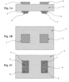
- Figures 1A-1C show an embodiment for applying an electric field using electric field electrodes that are parallel to the sensing electrodes of a gas sensor.
- sensing electrodes 1 and 2 can be attached to substrate 3.
- the substrate 3 comprises an electrolyte.
- the substrate 3 can be formed of yttria stabilized zirconia (YSZ).
- the sensing electrodes 1 and 2 are formed of different materials.
- the first sensing electrode 1 is formed of La 2 Cu04
- the second sensing electrode 2 can be formed of platinum (Pt).
- An electrochemical cell is formed since the first electrode 1 and second electrode 2 are in contact with the substrate 3.
- the sensing electrodes 1 and 2 can be provided in a single gas environment.
- electric-field electrodes can be provided to apply a parallel electric field.
- a first electric-field electrode 6 and a second electric-field electrode 8 can be provided corresponding to the first sensing electrode 1.
- a third electric-field electrode 7 and a fourth electric-field electrode 9 can be provided corresponding to the second sensing electrode 2.
- a first insulator 4 can be provided beneath the first and second electric-field electrodes 6 and 8 and the solid electrolyte 3
- a second insulator 5 can be provided between the third and fourth electric-field electrodes 7 and 9 and the solid electrolyte 3.
- the first and second insulators 4 and 5 can be formed of, for example, Al2O3.
- the electrodes of the electric-field electrodes are formed of a conductive material.
- the electrodes can be formed of gold (Au).
- a cap layer can be provided on each of the electric-field electrodes for insulation and improved adhesion.
- the cap layers can be formed of, for example, A1203.
- the insulation layers 4 and 5 allow the conduction layers of the electric-field electrodes 6 and 7 to not make contact with substrate 3. If substrate 3 is selected to be an electrolyte, then insulation layers 4 and 5, and conduction layers 6 and 7, are not considered part of the electrochemical cell.
- Figure 1B shows the top surface of the parallel-field embodiment shown in Figure 1A , with sensing electrode 1 and electrode 2 positioned on the substrate 3.
- Metallic leads or other metallization can be attached to the sensing electrodes in many ways. For the sensor application these leads can be used to transmit information about the electromotive field (EMF) at the electrode to a measurement device.
- EMF electromotive field
- Figure 1C shows the bottom surface of the parallel-field embodiment shown in Figure 1A , with insulation layer 4 and conduction layers 6 and 8 making up two "electric-field electrodes.”
- Metallic leads (not shown) can be attached to the electric-field electrodes in many ways.
- the electric-field electrodes may be used to "shape" the field profile in a device. This technique was tested in a gas sensor device and modeled to show how the field profile may change during "shaping.
- Figures 2A-2C show an embodiment for applying a shaped electric field to sensing electrodes of a planar gas sensor.
- sensing electrodes 13 and 17 are attached to a substrate 24 .
- the substrate 24 comprises an electrolyte.
- the substrate 3 is formed of electrolyte
- the substrate can be formed of YSZ.
- the sensing electrodes are formed of different material.
- the first sensing electrode 13 is formed of La 2 CuO4 and the second sensing electrode 17 can be formed of Pt.
- the first sensing electrode 13 , second sensing electrode 17 , and the substrate 24 make up an electrochemical cell.
- the sensing electrodes 13 and 17 can be provided in a single gas environment.
- Electric-field electrodes are provided at positions on the solid electrolyte 24 to apply an actively shaped electric field.
- a first electric-field electrode 11 can be provided in a ring shape around the first sensing electrode 13, and a second electric-field electrode 15 can be provided in a ring shape around the second sensing electrode 17.
- a third electric-field electrode 19 can be provided on the opposite side of the solid electrolyte 24 from the first sensing electrode 13 and in a ring shape corresponding to the first electric-field electrode 11, and a fourth electric-field electrode 22 can be provided on the opposite side of the solid electrolyte 24 from the second sensing electrode 17 and in a ring shape corresponding to the second electric-field electrode 15.
- a first insulator 10 can be provided in a ring shape between the first electric-field electrode 11 and the solid electrolyte 24, a second insulator 14 can be provided in a ring shape between the second electric-field electrode 15 and the solid electrolyte 24, a third insulator 18 can be provided in a ring shape between the third electric-field electrode 19 and the solid electrolyte 24, and a fourth insulator 21 can be provided in a ring shape between the fourth electric-field electrode 22 and the solid electrolyte 24.
- the first, second, third and fourth insulators 10, 14, 18 and 21 can be fonned of, for example, AI 2 O 3 .
- the electrodes of the electric-field electrodes are formed of a conductive material.
- the electrodes can be formed of gold (Au).
- a cap layer can be provided on each of the electric-field electrodes for insulation.
- a first cap layer 12 can be provided on the first electric-field electrode 11
- a second cap layer 16 can be provided on the second electric-field electrode 15
- a third cap layer 20 can be provided on the third electric-field electrode 19
- a fourth cap layer 23 can be provided on the fourth electric-field electrode 22.
- the cap layers can be formed of, for example, AI 2 O 3 .
- the cap layer may be omitted if desired.
- Metallic leads or other metallization may be sandwiched between the individual conduction layers and cap layers. The conduction layers of the electric-field electrodes do not make contact with substrate 24, though if desired the cap layer can do so. If substrate 24 is an electrolyte, then layers 10 through 12, 14 through 16, 18 through 20, and 21 through 23 are not part of the electrochemical cell.
- Figure 2B shows a top surface of the shaped-field embodiment, with sensing electrode 13 and electrode 17 attached to substrate 24.
- Metallic leads or other metallization can be attached to the sensing electrodes in many ways. For the sensor application these leads are used to transmit information about the EMF at the electrode to a measurement device. Multiple sensing electrodes and "electric-field electrodes" are incorporated into such a device and may make it a gas sensor array.
- Figure 2C shows a bottom surface of the shaped-field embodiment, with insulation layers 10, 14, 18, and 21, and conduction layers 11, 15, 19, and 22 making up four electric-field electrodes.
- Metallic leads (not shown) can be attached to an "electric-field electrodes" (making contact with the conduction layers) in many ways.
- These electric-field electrodes may also have geometries that are different from a ring-shape; in fact the sensing (or other active material) may be formed in a ring with the electric field electrode in arranged in the center.
- Different “charging schemes” may be used to get variations in the gas sensor sensitivity, selectivity, response time, etc. This is done by accumulating positive (+) or negative (-) charge via an applied voltage at any of conduction layers 11, 15, 19, and 22.
- Charging schemes 1 through 3 were tested using the shaped-field embodiment. Note, in charging scheme 6, conduction layers 11 (and 19) and 15 (and 22) have different charge values (i.e., the voltage applied to each is of a different magnitude). The other schemes are possible but have not been tested yet; they are included to show the advantages of a "shaped field" device.
- Figures 3A-3H illustrate the results from the shaped-field embodiment shown in Figures 2A-2C .
- the sensing electrodes 13 and 17 are La 2 CuO 4 and Pt, respectively.
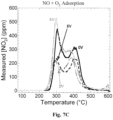
- Figure 3A represents the (potentiometric) NO sensor results from the shaped-field embodiment shown in Figures 2A-2C .
- the sensing electrodes are Pt and La 2 CuO 4 , which were exposed to the same gas environment (i.e., no air-reference).
- This plot compares the conditions with no electric field to those with a +1V bias using charging scheme 1 at 450C, 500C, 550C, and 600C.
- the top electric-field electrodes (surrounding the Pt and La 2 CuO 4 sensing electrodes) were positively biased.
- the corresponding "electric-field electrodes" on the opposite side of the substrate were both negatively biased. In other words, a voltage was applied between the top field electrodes (high potential) and the bottom field electrodes (low potential).
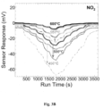
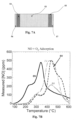
- Figure 3B represents the NO 2 sensor results from the shaped-field embodiment shown in Figures 2A-2C .
- the sensing electrodes are Pt and La 2 Cu04. This plot compares the conditions with no electric field to those with a +1V bias using charging scheme 1.
- the top electric-field electrodes (surrounding the Pt and La 2 Cu04 sensing electrodes) were positively biased.
- the corresponding "electric-field electrodes" on the opposite side of the substrate were both negatively biased.
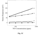
- FIG 3C shows the steady state sensor response of the shaped-field embodiment shown in Figures 2A-2C .
- charging scheme 1 (table 2) was used to apply negative (-) biases of different strength to top "electric field electrodes (surrounding the Pt and La 2 CuO 4 sensing electrodes).
- the corresponding "electric-field electrodes" on the opposite side of the substrate were both positively biased.
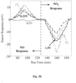
- Figures 3E shows the NO and NO2 sensor response for biasing scheme 2 (Table 2) applied to the embodiment shown in Figures 2A-2C .
- a high potential was applied to the electric field electrode surrounding the La2Cu04 sensing electrode (conduction layer 11) and at the electric field electrode on the opposite side of the substrate, aligned with the Pt sensing electrode (conduction layer 22).
- a low potential was applied at the electric field electrode surrounding the Pt sensing electrode (conduction layer 15) and at the electric field electrode on the opposite side of the substrate, aligned with the La2Cu04 electrode (conduction layer 19).
- negative (-) bias the high and low potentials applied at the electric field electrodes were reversed.
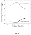
- Figure 3F and 3G show the NO and N02 sensitivity results for biasing scheme 3 applied to the embodiment shown in Figures 2A-2C .
- a negative bias was applied to the electric field electrodes (conduction layer 11) surrounding the La2Cu04 sensing electrode, with a positive bias applied to the corresponding electric field electrode on the opposite side of the substrate (conduction layer 19).
- Figure 3H shows the NO and N02 sensitivity results for biasing scheme 4 applied to the embodiment shown in Figures 2A-2C .
- a positive (or negative (- )) bias was applied to the electric field electrodes (conduction layer 15) surrounding the Pt sensing electrode, with a negative (or positive) bias applied to the corresponding electric field electrode on the opposite side of the substrate (conduction layer 22).
- Charging scheme 1 (Table 2) resulted in extremely large (-20X increase in NO sensitivity and ⁇ 10X increase in N02 sensitivity) as shown in Figures 3C and 3D . Furthermore, the sensitivity to N02 starts off negative and trends towards zero sensitivity before achieving a positive response. At the same time, the NO response only becomes increasingly positive. Therefore, it is possible that NO selectivity over N02 can be achieved.
- charging scheme 2 shown in Figure 3E demonstrates the capability of a shaped electric field to further enhance a gas sensor.
- a positive field bias resulted in an increased N02 response with increased bias, with a slightly increased NO sensitivity but no additional changes as the bias increased.
- negative field biases resulted in decreased NO sensitivity to almost zero, while maintaining NO sensitivity.
- the NO sensitivity was negligible while the NO2 sensitivity actually increased.
- charging scheme 3 (Table 2) resulted in similar changes in both NO and NO2 sensitivity as the electric field bias was changed. This suggests that this charging scheme might be used for achieving an enhanced total-NOx sensor signal.
- Figure 3H further demonstrates the ability of the various shaped electric fields to enhance a device in a number of ways.
- the results indicate that the bias scheme may result in NO selectivity because the N02 sensitivity trends toward zero while the NO sensitivity remains relatively unchanged.
- the fact that different results were achieved for each shaped field bias schemes suggests that similar enhancements can be used to improve other electrochemical devices, non-electrochemical devices, and other related processes.
- FIG 4A is a representation of the electric-field contour map 25 showing relative field strengths for the shaped-field embodiment of Figures 2A-2C using charging scheme 3.
- “electric-field electrode” 26 has a positive charge
- “electric-field electrode” 28 has a negative charge of equal magnitude
- “Electric-field electrodes” 27 and 29 are left floating.
- Each contour 25 in the figure represents different field strengths moving away from the device surface and throughout the gas environment surrounding the device. While not shown, it should be noted that the field contours also extend through substrate 30 and other parts of device (i.e., the field penetrates the device).
- FIG 4B is a representation of the electric-field vector map 31 for the same charging scheme as was presented in Figure 4A .
- Each arrow in the figure represents the direction of the electric field in space. The electric field moves from regions of positive to negative charge.
- the electric field contour map and electric field vector map in Figures 4A and 4B will change depending on the values of several parameters (e.g., the voltage at the "electric-field electrodes" and/or the charging scheme used).
- the field vectors also extend through substrate 30 and other parts of device (i.e., the field penetrates the device). Also, note that fringing effects near the edges of the "electric-field" electrodes have not been considered in the ideal case.
- FIG 4C is a representation of the electric-field vector map 32 for charging scheme 1 of the shaped-field embodiment in Figures 2A-2C .
- “electric-field electrodes” 33 and 34 have a positive charge
- “electric-field electrodes” 35 and 36 have a negative charge.
- the electric field is uniform near the center of the rings making up "electric-field electrodes" 33, 34, 35 and 36.
- the direction of the field vectors through the middle of the rings is the same for the left pair of rings (33 and 35) as it is for the right pair of rings (34 and 36).
- FIG 4D is a representation of the electric-field vector map 38 for charging scheme 2 of the shaped-field embodiment in Figures 2A-2C .
- “electric-field electrodes” 39 and 42 have a positive charge
- “electric-field electrodes” 40 and 41 have a negative charge.
- the electric field is uniform near the center of the rings making up "electric-field electrodes" 39, 40, 41 and 42.
- the field vector direction through the middle of the rings is NOT the same for the left pair of rings (39 and 41) as it is for the right pair of rings (40 and 42); the directions are opposite each other (and perpendicular to the surface).
- the field distribution in this scheme is symmetric about the device and surrounding gas environment (assuming ideal case and no interference from neighboring objects). While this latter fact, mirrors the situation displayed in Figure 4C , the field in between the two pairs of rings (i.e., at the very middle of the device) is no longer perpendicular to the surface; rather the field is now parallel to the surface.
- This electric field vector map will change depending on the values of the voltage at the "electric-field electrodes" (and if the charging scheme changes). While not shown, it should be noted that the field vectors also extend through substrate 43 and other parts of device (i.e., the field penetrates the device). Also, in addition to differences in the field vector map between charging schemes 2 ( Figure 4D ) and 1 ( Figure 4C ), it is worth noting that the field strength represented by the contour map for these two instances have also changed (not shown).
- Figures 4A-4D are simple 2D models mainly to represent the idea that different charging schemes (and embodiments) can allow the electric-field enhancement to be (actively) fine tuned in a device or general catalysis process.
- the field distribution, etc. may be different in a real device or process because the presence of the sensing electrodes and other components will also contribute to the field, making it different from the simple cases shown.
- the electrostatic and chemical interaction with the device, catalyst, gas, adsorbates, etc. will depend on these field contour and vector maps. Therefore, these interactions can be (actively) fine tuned depending on the device or general catalysis process for a given application.
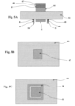
- Figure 5A represents a sensor embodiment utilizing an air-reference electrode 51. This embodiment was used to show that catalytic reactions are changing during use of the electric field electrodes, as exhibited by alteration of the measured gas composition. Insulation layers 45 and 48, conduction layers 46 and 49, and cap layers 47 and 50 making up four "electric-field electrodes.” Sensing electrode 44 and air-reference electrode 51 are attached to substrate (electrolyte) 52.
- Figure 5B shows a top surface of the air-reference sample with "electric-field electrodes" embodiment, with cap layer 47 shown.
- Metallic leads or other metallization can be attached to the sensing or air-reference electrodes in many ways. For the sensor application these leads are used to transmit information about the EMF at the electrode to a measurement device. Multiple sensing electrodes and "electric-field electrodes" are incorporated into such a device and may make it a gas sensor array.
- Figure 5C shows a bottom surface of the air-reference sample with "electric-field electrodes" embodiment, Air-reference electrode 51 is attached to substrate 52, and surrounded by the "electric-field electrode on this surface. From this viewpoint, the cap layer 50 is visible.
- This sensor device includes a first, rectangular ring-shaped "electric-field electrode" on one side of an electrolyte. In the middle this rings, a Pt air-reference electrode was deposited. On the opposite side, a La 2 CuO 4 electrode was attached to the electrolyte. On top of this electrode was a second, plate-shaped "electric-field electrode". The La2Cu04 electrode and second field electrode were exposed to the active gas stream, while the Pt air-reference and first field electrode remained at constant oxygen partial pressure (i.e., air).
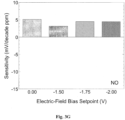
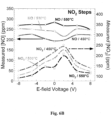
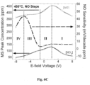
- the sensor was evaluated for multiple NOx concentrations in 3% 02 under an "electric-field electrode" bias of 0, 2, 5, and 8 V in the positive (high potential on La2Cu04 side) and negative (high potential on Pt side) directions. These tests were performed at temperatures of 450°C, 500°C, and 550°C and repeated twice for each condition.
- the sensors under the influence of the electric field were compared to the unbiased device at each temperature.
- the sensor signals were very low at 550C and 500C, which resulted in little or no change in sensitivity with applied field (not shown), except for the - 8 V setpoint with NO at 500C.
- TPD is an experimental technique in which initial quantities of a gas are adsorbed at relatively low temperatures (e.g., 300C) and then cooled to room temperature. The gas of interest is then shut off, and an inert gas such as helium is flowed through the reactor. The temperature is then ramped at high linear rate (e.g., 30°C/min) as the evolution of desorbed species is monitored with a mass spectrometer.
- relatively low temperatures e.g. 300C
- inert gas such as helium
- the results from the Sensor embodiments in accordance with the subject invention can utilize potentiometric, impedancemetric, and/or amperometric measurements.
- the sensors can locate all of the electrodes in the same gas environment and can use an air reference or some other type of reference.
- the voltage(s) applied to the "electric-field electrodes” may be alternatively supplied with a potentiostat or other device that keeps the charge at the "electric-field electrodes” equal to the desired value. In this way if the gas environment (or some phenomena) causes the charge to change, the potentiostat or other device can counteract to ensure the charge returns to the desired value.
- the charge may be calculated from a measured current change with time as, at least in the ideal case, there is no electronic current flowing through the device as a result of the applied voltage to the "electric-field electrodes". This current measured in the "circuit" occurs as a result of changes in the accumulated charge at the insulating layer, which is only a perfect insulator in the ideal case,
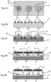
- Figures 8A-8H represent some of the other various configurations, which are not covered by the subject-matter of the claims, in which the electric-field enhancements may be used.
- Figure 8A shows a top view of a substrate 58 (electrolyte or other material), with each sensing electrode 59, 60, and 61 surrounded by several "electric-field electrodes" 62, 63, and 64 forming a dashed ring shape around the sensing electrodes.
- the electric-field electrodes are shown as one body, consisting of at least an insulating layer and conducting layer and possibly a cap layer as was shown in the embodiment of Figure 2A-2C .
- Figure 8B shows the cross-section of Figure 8A , with the sensing electrodes 59, 60, and 61 and "electric-field electrodes" 62, 63, and 64 displayed on one surface and heater structures 65, 66, and 67 (serpentine or other pattern) on a second surface.
- Figure 8C shows the cross-section of 8A, but now with the "electric field electrodes” 62, 63, and 64 and heater structures 65, 66, and 67 embedded within the substrate 58. Furthermore, there is a new layer 68 (electrolyte or other material) between the substrate 58 and sensing electrodes 59, 60, and 61.
- Figures 8D and 8E show cross-sections of Figure 8A , with heater structures 65, 66, and 67 embedded in the substrate and second layer 68 between substrate 58 and sensing electrodes 59, 60, and 61; the electric-field electrodes 70, 71, and 72 now have the form of plate-like shapes rather than the dashed arrangement seen in Figure 8A .
- Figure 8D shows a structure 69 that creates a cavity above each sensing electrode 59, 60, and 61; the electric field electrodes 70, 71, and 72 are attached to the inner side of this structure.
- Figure 8E shows a similar cavity creating structure 69, but with the electric field electrodes 70, 71, and 72 on the top surface of this structure.
- Figures 8F-8H show several additional configurations of devices utilizing the electric-field enhancements.
- Figure 8F shows the top view of the embodiment with two rectangular layers 83 and 84 (electrolyte or other material) on top of the substrate 76 (electrolyte or other material) containing at least two sensing electrodes 79, 80, 81, and 82 each.
- Layers 83 and 84 serve to separate the sensing electrodes 79, 80, 81, and 82 from the substrate 76.
- Structures 77 and 78 surround each of these rectangular layers and represent several electric field electrodes in a dashed arrangement.
- Figure 8G represents a cross-section of Figure 8F , showing rectangular layers 83 and 84 and corresponding sensing electrodes 79, 80, 81, and 82. Also shown are electric-field electrodes 77 and 78, and heating structures 68 and 70 on the bottom surface.
- Figure 8H shows another possible embodiment where one of the rectangular layers ( 83 in 8F) with sensing electrodes ( 79 and 80 in 8F) are replaced with a gas sensitive material 85 (e.g., electrical resistance changes upon gas exposure) in contact with the substrate 76. Electrical contacts 86 and 87 are made to this material in two places. The remainder of this embodiment is the same as in Figure 8G .
- a gas sensitive material 85 e.g., electrical resistance changes upon gas exposure
- a fuel cell e.g., SOFC
- oxygen is dissociation on the cathode and fuel dissociation and reactions at the anode.
- an electric field can stabilize/destabilize adsorbate complexes on a surface. This may result in alterations to the kinetics or reaction mechanisms that will improve the performance of a fuel cell (e.g., enhance power density output).
- removal or prevention of the buildup of poisons from the fuel cell surface, particularly at the fuel side can be accomplished in accordance with embodiments of the invention using "electric-field electrodes".
- the use of "electric-field electrodes" with SOFC can lower the operating temperatures and allow the use of cheaper materials in the fuel cells.
- the electric-electrodes may be used to modify the device for enhanced or maintained performance when load conditions change.
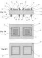
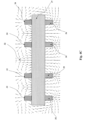
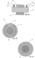
- Figure 9A represents an electric-field enhanced, electrochemical cell (e.g., fuel cell) embodiment, which is not covered by the subject-matter of the claims.
- substrate 95 which may be an electrolyte, has an attached anode (88 or 96) and cathode (96 or 88).
- other materials serve as the support or other support material, such as an anode support, with the electrolyte and other corresponding layers on top.
- Different arrangements can be used where the device is anode supported, and the electrolyte is a very thin layer attached to the support.
- the cathode can then be deposited on top of the electrolyte, completing the cell.
- the "electric-field electrodes” are made up of insulation layers 89 and 92, conduction layers 90 and 93, and cap layers 91 and 94. Metallic leads, or other interconnections (not shown), may be attached to the electrodes in many different ways. This arrangement also may be formed into a stack made up of multiple cells.
- Figure 9B is one surface of the electrochemical cell (e.g., fuel cell) embodiment, which is not covered by the subject-matter of the claims.
- cap layers 91 and 94 are visible.
- Electrode 88 may be the anode or cathode and is attached to substrate 95.
- Figure 9C is another surface of the fuel cell embodiment, which is not covered by the subject-matter of the claims. Here only electrode 96 is visible. It is attached to substrate 95 and may be the anode or cathode.
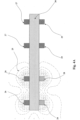
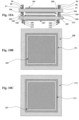
- Figures 10A-10C show a different electric-field enhanced, electro-chemical device (e.g., fuel cell) embodiment, which is not covered by the subject-matter of the claims, in a planar configuration. Shown is a stack configuration which may consist of any number of cells.
- FIG 10A several electric field electrodes exist, consisting of conducting layers 98, 103, and 110 insulating layers 97, 99, 102, 104, 109, and 111.
- FIG. 10B shows the top surface of the embodiment in Figure 10A with substrate 100, electrode 101 (anode or cathode), and insulating layer 99 of an electric field electrode.
- Figure 10C shows the bottom surface of the embodiment in Figure 10A with substrate 112, electrode 107 (anode or cathode), and insulating layer 111 of an electric field electrode.
- NEMCA can greatly enhance catalytic reaction rates.
- the electric field created by the applied potential or (electronic) current to the cell electrodes is limited due to the fact that increased potential (and thus field strengths) can result in permanent damage of the device.
- use of the "electric-field electrodes” can enhance the NEMCA electric field.
- the "electric-field electrodes” can have more control over adsorption and reactions than NEMCA because they may be located anywhere on the device.
- catalytic reactions may be altered with the use of electric fields.
- the "electric-field electrodes” may be incorporated into a catalyst support and thereby alter reaction pathways in a desirable way. Improvements include increased conversion yield and/or lower temperature requirements for reactions. This can result in lower costs and improved profitability for catalytic reactions.
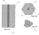
- Figure 11A represents a cross-section of catalyst bed not in the scope of the present invention used in catalysis processes.
- Metal core 113 is embedded through the middle of honeycomb 115.
- Outer electrode 114 is attached to the perimeter of honeycomb 115.
- the honeycomb pattern also may be another related shape, whose purpose is to hold catalyst particles 116.
- Honeycomb 115 is a polygonal-cylinder, and a voltage is applied between metal core 113 and outer electrode 114 to create an electric field around the catalyst particles which are dispersed throughout the honeycomb 115 structure.
- the reactant gas is flowed through the honeycomb 115 structure, where it can react on the catalyst particles.
- the honeycomb 115 structure can also be made from an electrolyte material.
- FIG. 11B represents a top view of the polygonal-cylinder shape, with metal core 113 and outer electrode 114 shown.
- the honeycomb 115 structure is also shown.
- Figure 11C represents a cluster of catalyst particles 116 that could be dispersed throughout the honeycomb structure seen in Figures 11A and 11B .
- Figure 11B represents a top view of the polygonal-cylinder shape, with metal core 77 and outer electrode 78 shown.
- the honeycomb 79 structure is also shown
- Figure 11C represents a cluster of catalyst particles 80 , which are not covered by the subject-matter of the claims, that could be dispersed throughout the honeycomb structure seen in Figures 11A and 11B ,
Landscapes
- Chemical & Material Sciences (AREA)
- Life Sciences & Earth Sciences (AREA)
- Health & Medical Sciences (AREA)
- Electrochemistry (AREA)
- Chemical Kinetics & Catalysis (AREA)
- Analytical Chemistry (AREA)
- General Health & Medical Sciences (AREA)
- Pathology (AREA)
- Immunology (AREA)
- General Physics & Mathematics (AREA)
- Molecular Biology (AREA)
- Physics & Mathematics (AREA)
- Biochemistry (AREA)
- General Chemical & Material Sciences (AREA)
- Engineering & Computer Science (AREA)
- Sustainable Energy (AREA)
- Manufacturing & Machinery (AREA)
- Sustainable Development (AREA)
- Catalysts (AREA)
- Investigating Or Analyzing Materials By The Use Of Electric Means (AREA)
- Fuel Cell (AREA)
- Measuring Oxygen Concentration In Cells (AREA)
- Physical Or Chemical Processes And Apparatus (AREA)
- Inert Electrodes (AREA)
Applications Claiming Priority (4)
| Application Number | Priority Date | Filing Date | Title |
|---|---|---|---|
| US1328707P | 2007-12-12 | 2007-12-12 | |
| US1328707A | 2007-12-12 | 2007-12-12 | |
| EP08858798.5A EP2240976B1 (en) | 2007-12-12 | 2008-12-12 | Electric-field enhanced performance in solid electrolyte devices involving gases |
| PCT/US2008/086693 WO2009076644A2 (en) | 2007-12-12 | 2008-12-12 | Electric-field enhanced performance in catalysis and solid-state devices involving gases |
Related Parent Applications (1)
| Application Number | Title | Priority Date | Filing Date |
|---|---|---|---|
| EP08858798.5A Division EP2240976B1 (en) | 2007-12-12 | 2008-12-12 | Electric-field enhanced performance in solid electrolyte devices involving gases |
Publications (2)
| Publication Number | Publication Date |
|---|---|
| EP3206023A1 EP3206023A1 (en) | 2017-08-16 |
| EP3206023B1 true EP3206023B1 (en) | 2024-03-13 |
Family
ID=40756145
Family Applications (2)
| Application Number | Title | Priority Date | Filing Date |
|---|---|---|---|
| EP17164764.7A Active EP3206023B1 (en) | 2007-12-12 | 2008-12-12 | Electric-field enhanced performance in catalysis and solid-state devices involving gases |
| EP08858798.5A Active EP2240976B1 (en) | 2007-12-12 | 2008-12-12 | Electric-field enhanced performance in solid electrolyte devices involving gases |
Family Applications After (1)
| Application Number | Title | Priority Date | Filing Date |
|---|---|---|---|
| EP08858798.5A Active EP2240976B1 (en) | 2007-12-12 | 2008-12-12 | Electric-field enhanced performance in solid electrolyte devices involving gases |
Country Status (9)
| Country | Link |
|---|---|
| US (2) | US9034170B2 (enExample) |
| EP (2) | EP3206023B1 (enExample) |
| JP (3) | JP5666913B2 (enExample) |
| KR (2) | KR101737620B1 (enExample) |
| CN (1) | CN101897066B (enExample) |
| BR (1) | BRPI0821184B1 (enExample) |
| CA (2) | CA2969956A1 (enExample) |
| ES (1) | ES2637797T3 (enExample) |
| WO (1) | WO2009076644A2 (enExample) |
Families Citing this family (15)
| Publication number | Priority date | Publication date | Assignee | Title |
|---|---|---|---|---|
| US8294476B2 (en) * | 2010-05-03 | 2012-10-23 | Sensorbit Systems, Inc. | Method of sensor cell timing |
| US8453494B2 (en) * | 2010-09-13 | 2013-06-04 | National Semiconductor Corporation | Gas detector that utilizes an electric field to assist in the collection and removal of gas molecules |
| US9169976B2 (en) | 2011-11-21 | 2015-10-27 | Ardica Technologies, Inc. | Method of manufacture of a metal hydride fuel supply |
| US20130224614A1 (en) * | 2012-02-27 | 2013-08-29 | Ardica Technologies, Inc. | Field-enhanced thermal decomposition of fuel storage compositions |
| CN104868148B (zh) * | 2015-04-22 | 2017-07-21 | 陈海辉 | 电场直流增强式燃料电池反应器的工业放大方法及装置 |
| NL2019492B1 (en) * | 2017-09-06 | 2019-03-14 | Boston Scient Scimed Inc | Systems and methods for analyte sensing in physiological gas samples |
| US10852264B2 (en) | 2017-07-18 | 2020-12-01 | Boston Scientific Scimed, Inc. | Systems and methods for analyte sensing in physiological gas samples |
| TWI673493B (zh) * | 2018-10-26 | 2019-10-01 | 國立交通大學 | 氣體感測器 |
| EP3861329A1 (en) | 2018-11-27 | 2021-08-11 | Boston Scientific Scimed Inc. | Systems and methods for detecting a health condition |
| EP3899515B1 (en) | 2018-12-18 | 2023-01-25 | Boston Scientific Scimed Inc. | Systems and methods for measuring kinetic response of chemical sensor elements comprising graphene varactors |
| US11162928B2 (en) * | 2019-11-04 | 2021-11-02 | Invensense, Inc. | Humidity correction method in thermistor based gas sensing platform |
| KR102553115B1 (ko) * | 2020-02-26 | 2023-07-07 | 한밭대학교 산학협력단 | 다공성 전극의 전기전도도 측정 방법 |
| DE102021203502A1 (de) * | 2021-04-09 | 2022-10-13 | Robert Bosch Gesellschaft mit beschränkter Haftung | Verfahren zum Betrieb eines Brennstoffumsetzungssystems und ein Brennstoffumsetzungssystem zur Durchführung eines derartigen Verfahrens |
| US12480907B2 (en) | 2021-04-16 | 2025-11-25 | Regents Of The University Of Minnesota | Systems utilizing graphene varactor hysteresis effects for sample characterization |
| CN113252122A (zh) * | 2021-05-18 | 2021-08-13 | 山东科尔自动化仪表股份有限公司 | 一种电荷流量计及流量计量方法 |
Family Cites Families (37)
| Publication number | Priority date | Publication date | Assignee | Title |
|---|---|---|---|---|
| US3149921A (en) * | 1961-07-20 | 1964-09-22 | Gen Electric | Method of measuring the partial pressure of a gas |
| US3475882A (en) * | 1968-06-14 | 1969-11-04 | Battelle Development Corp | Separating components in gases |
| JPH0429405Y2 (enExample) * | 1985-05-29 | 1992-07-16 | ||
| US4795968A (en) * | 1986-06-30 | 1989-01-03 | Sri International | Gas detection method and apparatus using chemisorption and/or physisorption |
| US5389218A (en) | 1989-01-24 | 1995-02-14 | Gas Research Institute | Process for operating a solid-state oxygen microsensor |
| US5389225A (en) | 1989-01-24 | 1995-02-14 | Gas Research Institute | Solid-state oxygen microsensor and thin structure therefor |
| JP3169617B2 (ja) * | 1989-12-27 | 2001-05-28 | 日本石油化学株式会社 | 電気伝導度制御方法 |
| US5841021A (en) * | 1995-09-05 | 1998-11-24 | De Castro; Emory S. | Solid state gas sensor and filter assembly |
| JP3272215B2 (ja) | 1995-10-20 | 2002-04-08 | 日本碍子株式会社 | NOxセンサ及びNOx測定方法 |
| JPH10239276A (ja) | 1996-12-27 | 1998-09-11 | Ngk Insulators Ltd | 一酸化炭素ガスセンサおよび同センサを用いた測定装置 |
| JPH10282035A (ja) * | 1997-04-02 | 1998-10-23 | Sekiyu Kodan | 混合物体積割合測定センサ |
| JPH11169645A (ja) * | 1997-12-11 | 1999-06-29 | Sekisui Chem Co Ltd | ガス分解処理方法 |
| JP3613661B2 (ja) * | 1998-12-15 | 2005-01-26 | トヨタ自動車株式会社 | 酸素濃度検出装置 |
| DE19956823C2 (de) * | 1999-11-25 | 2002-11-28 | Siemens Ag | Ansteuerschaltung und Ansteuerverfahren für einen Gassensor |
| JP2001183334A (ja) * | 1999-12-27 | 2001-07-06 | Ngk Spark Plug Co Ltd | ヒータ付きガスセンサ素子の絶縁検査方法 |
| JP2002174618A (ja) | 2000-12-07 | 2002-06-21 | Matsushita Electric Ind Co Ltd | 固体電解質型ガスセンサ |
| US6691554B2 (en) * | 2001-04-11 | 2004-02-17 | The University Of Chicago | Nanocrystalline films for gas-reactive applications |
| JP2003107044A (ja) * | 2001-09-28 | 2003-04-09 | Matsushita Electric Ind Co Ltd | 酸素ポンプ素子および酸素ポンプ装置 |
| JP2003107045A (ja) * | 2001-09-28 | 2003-04-09 | Matsushita Electric Ind Co Ltd | 酸素ポンプ素子および酸素ポンプ装置 |
| JP2003187822A (ja) * | 2001-12-20 | 2003-07-04 | Sony Corp | プロトン伝導体、膜電極接合体、燃料電池、燃料電池装置、並びに電圧変換装置 |
| WO2003069304A2 (en) * | 2002-02-10 | 2003-08-21 | Agamatrix, Inc | Method and apparatus for assay of electrochemical properties |
| DE10210819B4 (de) | 2002-03-12 | 2004-04-15 | Micronas Gmbh | Mikrostrukturierter Gassensor mit Steuerung der gassensitiven Eigenschaften durch Anlegen eines elektrischen Feldes |
| JP4534423B2 (ja) * | 2002-07-30 | 2010-09-01 | アイシン精機株式会社 | 燃料電池の制御方法 |
| JP4367441B2 (ja) * | 2002-08-20 | 2009-11-18 | ソニー株式会社 | ハイブリダイゼーション方法 |
| DE10259819B4 (de) * | 2002-12-19 | 2006-07-13 | Siemens Ag | Verfahren zur PCR-Amplifikation und Detektion von Nucleotidsequenzen |
| DE10308395A1 (de) * | 2003-02-27 | 2004-09-09 | Robert Bosch Gmbh | Sensorelement eines Gassensors |
| US7419734B2 (en) * | 2003-05-16 | 2008-09-02 | Ballard Power Systems, Inc. | Method and apparatus for fuel cell systems |
| US7279665B2 (en) * | 2003-07-02 | 2007-10-09 | Itherm Technologies, Lp | Method for delivering harmonic inductive power |
| US7258773B2 (en) * | 2003-08-12 | 2007-08-21 | Rae Systems, Inc. | Solid polymer electrolyte oxygen sensor |
| GB0323417D0 (en) * | 2003-10-07 | 2003-11-05 | Boc Group Plc | Electrochemical sensor |
| US7264700B1 (en) * | 2004-01-20 | 2007-09-04 | Los Alamos National Security, Llc | Thin film mixed potential sensors |
| US20060000259A1 (en) * | 2004-05-17 | 2006-01-05 | Massachusetts Institute Of Technology | Photo-induced sensitivity and selectivity of semiconductor gas sensors |
| US20060189142A1 (en) * | 2004-06-30 | 2006-08-24 | Yuji Saito | Method for making a sub-micron solid oxide electrolyte membrane |
| JP2006133039A (ja) * | 2004-11-04 | 2006-05-25 | Riken Corp | 窒素酸化物センサ |
| US7294252B2 (en) * | 2005-10-07 | 2007-11-13 | Delphi Technologies, Inc. | NOx sensor and methods of using the same |
| JP5252362B2 (ja) * | 2005-12-28 | 2013-07-31 | 独立行政法人産業技術総合研究所 | セラミック電極 |
| KR20090125114A (ko) * | 2007-03-15 | 2009-12-03 | 니뽄 가이시 가부시키가이샤 | 입자상 물질 검출 장치 및 입자상 물질 검출 방법 |
-
2008
- 2008-12-12 BR BRPI0821184-1A patent/BRPI0821184B1/pt not_active IP Right Cessation
- 2008-12-12 CA CA2969956A patent/CA2969956A1/en not_active Abandoned
- 2008-12-12 ES ES08858798.5T patent/ES2637797T3/es active Active
- 2008-12-12 EP EP17164764.7A patent/EP3206023B1/en active Active
- 2008-12-12 EP EP08858798.5A patent/EP2240976B1/en active Active
- 2008-12-12 KR KR1020107012822A patent/KR101737620B1/ko active Active
- 2008-12-12 CN CN200880120515.8A patent/CN101897066B/zh not_active Expired - Fee Related
- 2008-12-12 JP JP2010538211A patent/JP5666913B2/ja active Active
- 2008-12-12 US US12/743,490 patent/US9034170B2/en active Active
- 2008-12-12 CA CA2706387A patent/CA2706387C/en active Active
- 2008-12-12 WO PCT/US2008/086693 patent/WO2009076644A2/en not_active Ceased
-
2014
- 2014-12-11 JP JP2014250718A patent/JP6033831B2/ja active Active
-
2015
- 2015-05-18 US US14/714,860 patent/US10197521B2/en active Active
- 2015-11-19 KR KR1020150162815A patent/KR101737622B1/ko active Active
-
2016
- 2016-10-26 JP JP2016209182A patent/JP6415510B2/ja active Active
Also Published As
| Publication number | Publication date |
|---|---|
| KR20100101599A (ko) | 2010-09-17 |
| BRPI0821184A2 (pt) | 2017-05-09 |
| JP5666913B2 (ja) | 2015-02-12 |
| KR101737622B1 (ko) | 2017-05-18 |
| EP2240976B1 (en) | 2017-04-05 |
| HK1148870A1 (en) | 2011-09-16 |
| CA2969956A1 (en) | 2009-06-18 |
| JP2017096927A (ja) | 2017-06-01 |
| JP2015064380A (ja) | 2015-04-09 |
| CA2706387A1 (en) | 2009-06-18 |
| CN101897066A (zh) | 2010-11-24 |
| CN101897066B (zh) | 2015-05-06 |
| US20150253275A1 (en) | 2015-09-10 |
| ES2637797T3 (es) | 2017-10-17 |
| CA2706387C (en) | 2017-07-18 |
| JP2011506976A (ja) | 2011-03-03 |
| US9034170B2 (en) | 2015-05-19 |
| WO2009076644A3 (en) | 2009-09-11 |
| KR101737620B1 (ko) | 2017-05-18 |
| JP6415510B2 (ja) | 2018-10-31 |
| JP6033831B2 (ja) | 2016-11-30 |
| EP2240976A4 (en) | 2013-04-17 |
| EP3206023A1 (en) | 2017-08-16 |
| BRPI0821184B1 (pt) | 2019-05-07 |
| KR20150137044A (ko) | 2015-12-08 |
| EP2240976A2 (en) | 2010-10-20 |
| US20100323258A1 (en) | 2010-12-23 |
| WO2009076644A2 (en) | 2009-06-18 |
| US10197521B2 (en) | 2019-02-05 |
Similar Documents
| Publication | Publication Date | Title |
|---|---|---|
| EP3206023B1 (en) | Electric-field enhanced performance in catalysis and solid-state devices involving gases | |
| US6423193B1 (en) | Nitrogen doped carbon electrodes | |
| EP3786627B1 (en) | Mems type semiconductor gas detection element | |
| CN103890575B (zh) | 传感器和制造传感器的方法 | |
| KR101445590B1 (ko) | 수소 센서 및 수소 센서 제조방법 | |
| Lambert et al. | Modelling alkali promotion in heterogeneous catalysis: in situ electrochemical control of catalytic reactions | |
| US20170102353A1 (en) | Sensor in an internet-of-things and manufacturing method of the same | |
| Plashnitsa et al. | Zirconia-based planar NO2 sensor using ultrathin NiO or laminated NiO–Au sensing electrode | |
| Constantinou et al. | Electrochemical promotion of RuO2 catalysts for the combustion of toluene and ethylene | |
| Climent et al. | Clues for the molecular-level understanding of electrocatalysis on single-crystal platinum surfaces modified by p-block adatoms | |
| Fóti et al. | Electrochemical promotion of catalysis | |
| HK1148870B (en) | Electric-field enhanced performance in catalysis and solid-state devices involving gases | |
| Chun et al. | Transition effect of under-and over-potentially deposited hydrogen and negative resistance at a poly-Rh/alkaline aqueous solution interface | |
| JP2008014634A (ja) | 電気化学セル方式ガスセンサー | |
| JP2003075403A (ja) | ガスセンサ | |
| Reti et al. | Subjective overview on oxide semiconductor gas sensors | |
| Korotcenkov | Electrodes and Heaters in MOX-Based Gas Sensors | |
| Oad | on CaO and Y2O3-doped CeO2, 12 for Pt on YSZ, 10 and for Pt on Gd2O3-doped CeO2. 13 However | |
| Baranova | Chemical and Electrochemical Promotion of Supported Rhodium Catalyst | |
| Blackburn et al. | Electric-Field Effects in Solid-State Ionic Devices | |
| Abd-el-Salehin et al. | Model electrodes for the electrooxidation of simple alcohols: a DEMS study | |
| JPH06160344A (ja) | 電気化学素子 | |
| KR20140006385A (ko) | 전이금속 박막의 제조방법 |
Legal Events
| Date | Code | Title | Description |
|---|---|---|---|
| PUAI | Public reference made under article 153(3) epc to a published international application that has entered the european phase |
Free format text: ORIGINAL CODE: 0009012 |
|
| STAA | Information on the status of an ep patent application or granted ep patent |
Free format text: STATUS: THE APPLICATION HAS BEEN PUBLISHED |
|
| AC | Divisional application: reference to earlier application |
Ref document number: 2240976 Country of ref document: EP Kind code of ref document: P |
|
| AK | Designated contracting states |
Kind code of ref document: A1 Designated state(s): AT BE BG CH CY CZ DE DK EE ES FI FR GB GR HR HU IE IS IT LI LT LU LV MC MT NL NO PL PT RO SE SI SK TR |
|
| AX | Request for extension of the european patent |
Extension state: AL BA MK RS |
|
| STAA | Information on the status of an ep patent application or granted ep patent |
Free format text: STATUS: REQUEST FOR EXAMINATION WAS MADE |
|
| 17P | Request for examination filed |
Effective date: 20180216 |
|
| RBV | Designated contracting states (corrected) |
Designated state(s): AT BE BG CH CY CZ DE DK EE ES FI FR GB GR HR HU IE IS IT LI LT LU LV MC MT NL NO PL PT RO SE SI SK TR |
|
| STAA | Information on the status of an ep patent application or granted ep patent |
Free format text: STATUS: EXAMINATION IS IN PROGRESS |
|
| 17Q | First examination report despatched |
Effective date: 20181218 |
|
| STAA | Information on the status of an ep patent application or granted ep patent |
Free format text: STATUS: THE APPLICATION IS DEEMED TO BE WITHDRAWN |
|
| 18D | Application deemed to be withdrawn |
Effective date: 20190924 |
|
| 18RA | Request filed for re-establishment of rights before grant |
Effective date: 20201211 |
|
| STAA | Information on the status of an ep patent application or granted ep patent |
Free format text: STATUS: EXAMINATION IS IN PROGRESS |
|
| D18D | Application deemed to be withdrawn (deleted) | ||
| REG | Reference to a national code |
Ref country code: DE Ref legal event code: R079 Ref document number: 602008064979 Country of ref document: DE Free format text: PREVIOUS MAIN CLASS: G01N0027407000 Ipc: G01N0027406000 Ref country code: DE Ref legal event code: R079 Free format text: PREVIOUS MAIN CLASS: G01N0027407000 Ipc: G01N0027406000 |
|
| GRAP | Despatch of communication of intention to grant a patent |
Free format text: ORIGINAL CODE: EPIDOSNIGR1 |
|
| STAA | Information on the status of an ep patent application or granted ep patent |
Free format text: STATUS: GRANT OF PATENT IS INTENDED |
|
| RIC1 | Information provided on ipc code assigned before grant |
Ipc: H01M 8/04537 20160101ALI20230922BHEP Ipc: H01M 8/0432 20160101ALI20230922BHEP Ipc: G01N 27/407 20060101ALI20230922BHEP Ipc: G01N 27/406 20060101AFI20230922BHEP |
|
| INTG | Intention to grant announced |
Effective date: 20231024 |
|
| GRAS | Grant fee paid |
Free format text: ORIGINAL CODE: EPIDOSNIGR3 |
|
| GRAA | (expected) grant |
Free format text: ORIGINAL CODE: 0009210 |
|
| STAA | Information on the status of an ep patent application or granted ep patent |
Free format text: STATUS: THE PATENT HAS BEEN GRANTED |
|
| AC | Divisional application: reference to earlier application |
Ref document number: 2240976 Country of ref document: EP Kind code of ref document: P |
|
| AK | Designated contracting states |
Kind code of ref document: B1 Designated state(s): AT BE BG CH CY CZ DE DK EE ES FI FR GB GR HR HU IE IS IT LI LT LU LV MC MT NL NO PL PT RO SE SI SK TR |
|
| REG | Reference to a national code |
Ref country code: CH Ref legal event code: EP |
|
| REG | Reference to a national code |
Ref country code: DE Ref legal event code: R096 Ref document number: 602008064979 Country of ref document: DE |
|
| REG | Reference to a national code |
Ref country code: IE Ref legal event code: FG4D |
|
| PG25 | Lapsed in a contracting state [announced via postgrant information from national office to epo] |
Ref country code: LT Free format text: LAPSE BECAUSE OF FAILURE TO SUBMIT A TRANSLATION OF THE DESCRIPTION OR TO PAY THE FEE WITHIN THE PRESCRIBED TIME-LIMIT Effective date: 20240313 |
|
| REG | Reference to a national code |
Ref country code: LT Ref legal event code: MG9D |
|
| PG25 | Lapsed in a contracting state [announced via postgrant information from national office to epo] |
Ref country code: GR Free format text: LAPSE BECAUSE OF FAILURE TO SUBMIT A TRANSLATION OF THE DESCRIPTION OR TO PAY THE FEE WITHIN THE PRESCRIBED TIME-LIMIT Effective date: 20240614 |
|
| REG | Reference to a national code |
Ref country code: NL Ref legal event code: MP Effective date: 20240313 |
|
| PG25 | Lapsed in a contracting state [announced via postgrant information from national office to epo] |
Ref country code: HR Free format text: LAPSE BECAUSE OF FAILURE TO SUBMIT A TRANSLATION OF THE DESCRIPTION OR TO PAY THE FEE WITHIN THE PRESCRIBED TIME-LIMIT Effective date: 20240313 |
|
| PG25 | Lapsed in a contracting state [announced via postgrant information from national office to epo] |
Ref country code: ES Free format text: LAPSE BECAUSE OF FAILURE TO SUBMIT A TRANSLATION OF THE DESCRIPTION OR TO PAY THE FEE WITHIN THE PRESCRIBED TIME-LIMIT Effective date: 20240313 |
|
| PG25 | Lapsed in a contracting state [announced via postgrant information from national office to epo] |
Ref country code: NO Free format text: LAPSE BECAUSE OF FAILURE TO SUBMIT A TRANSLATION OF THE DESCRIPTION OR TO PAY THE FEE WITHIN THE PRESCRIBED TIME-LIMIT Effective date: 20240613 Ref country code: LT Free format text: LAPSE BECAUSE OF FAILURE TO SUBMIT A TRANSLATION OF THE DESCRIPTION OR TO PAY THE FEE WITHIN THE PRESCRIBED TIME-LIMIT Effective date: 20240313 Ref country code: HR Free format text: LAPSE BECAUSE OF FAILURE TO SUBMIT A TRANSLATION OF THE DESCRIPTION OR TO PAY THE FEE WITHIN THE PRESCRIBED TIME-LIMIT Effective date: 20240313 Ref country code: GR Free format text: LAPSE BECAUSE OF FAILURE TO SUBMIT A TRANSLATION OF THE DESCRIPTION OR TO PAY THE FEE WITHIN THE PRESCRIBED TIME-LIMIT Effective date: 20240614 Ref country code: FI Free format text: LAPSE BECAUSE OF FAILURE TO SUBMIT A TRANSLATION OF THE DESCRIPTION OR TO PAY THE FEE WITHIN THE PRESCRIBED TIME-LIMIT Effective date: 20240313 Ref country code: ES Free format text: LAPSE BECAUSE OF FAILURE TO SUBMIT A TRANSLATION OF THE DESCRIPTION OR TO PAY THE FEE WITHIN THE PRESCRIBED TIME-LIMIT Effective date: 20240313 Ref country code: BG Free format text: LAPSE BECAUSE OF FAILURE TO SUBMIT A TRANSLATION OF THE DESCRIPTION OR TO PAY THE FEE WITHIN THE PRESCRIBED TIME-LIMIT Effective date: 20240313 |
|
| REG | Reference to a national code |
Ref country code: AT Ref legal event code: MK05 Ref document number: 1666198 Country of ref document: AT Kind code of ref document: T Effective date: 20240313 |
|
| PG25 | Lapsed in a contracting state [announced via postgrant information from national office to epo] |
Ref country code: SE Free format text: LAPSE BECAUSE OF FAILURE TO SUBMIT A TRANSLATION OF THE DESCRIPTION OR TO PAY THE FEE WITHIN THE PRESCRIBED TIME-LIMIT Effective date: 20240313 Ref country code: LV Free format text: LAPSE BECAUSE OF FAILURE TO SUBMIT A TRANSLATION OF THE DESCRIPTION OR TO PAY THE FEE WITHIN THE PRESCRIBED TIME-LIMIT Effective date: 20240313 |
|
| PG25 | Lapsed in a contracting state [announced via postgrant information from national office to epo] |
Ref country code: NL Free format text: LAPSE BECAUSE OF FAILURE TO SUBMIT A TRANSLATION OF THE DESCRIPTION OR TO PAY THE FEE WITHIN THE PRESCRIBED TIME-LIMIT Effective date: 20240313 |
|
| REG | Reference to a national code |
Ref country code: DE Ref legal event code: R082 Ref document number: 602008064979 Country of ref document: DE Representative=s name: BRAUN GREDING PATENTANWAELTE PARTNERSCHAFT MBB, DE Ref country code: DE Ref legal event code: R082 Ref document number: 602008064979 Country of ref document: DE Representative=s name: BRAUN GREDING PATENTANWAELTE GBR, DE Ref country code: DE Ref legal event code: R082 Ref document number: 602008064979 Country of ref document: DE Representative=s name: BERGGREN PATENTANWAELTE PARTNERSCHAFT MBB, DE |
|
| PG25 | Lapsed in a contracting state [announced via postgrant information from national office to epo] |
Ref country code: NL Free format text: LAPSE BECAUSE OF FAILURE TO SUBMIT A TRANSLATION OF THE DESCRIPTION OR TO PAY THE FEE WITHIN THE PRESCRIBED TIME-LIMIT Effective date: 20240313 |
|
| PG25 | Lapsed in a contracting state [announced via postgrant information from national office to epo] |
Ref country code: IS Free format text: LAPSE BECAUSE OF FAILURE TO SUBMIT A TRANSLATION OF THE DESCRIPTION OR TO PAY THE FEE WITHIN THE PRESCRIBED TIME-LIMIT Effective date: 20240713 |
|
| PG25 | Lapsed in a contracting state [announced via postgrant information from national office to epo] |
Ref country code: PT Free format text: LAPSE BECAUSE OF FAILURE TO SUBMIT A TRANSLATION OF THE DESCRIPTION OR TO PAY THE FEE WITHIN THE PRESCRIBED TIME-LIMIT Effective date: 20240715 |
|
| PG25 | Lapsed in a contracting state [announced via postgrant information from national office to epo] |
Ref country code: CZ Free format text: LAPSE BECAUSE OF FAILURE TO SUBMIT A TRANSLATION OF THE DESCRIPTION OR TO PAY THE FEE WITHIN THE PRESCRIBED TIME-LIMIT Effective date: 20240313 Ref country code: EE Free format text: LAPSE BECAUSE OF FAILURE TO SUBMIT A TRANSLATION OF THE DESCRIPTION OR TO PAY THE FEE WITHIN THE PRESCRIBED TIME-LIMIT Effective date: 20240313 |
|
| PG25 | Lapsed in a contracting state [announced via postgrant information from national office to epo] |
Ref country code: AT Free format text: LAPSE BECAUSE OF FAILURE TO SUBMIT A TRANSLATION OF THE DESCRIPTION OR TO PAY THE FEE WITHIN THE PRESCRIBED TIME-LIMIT Effective date: 20240313 |
|
| PG25 | Lapsed in a contracting state [announced via postgrant information from national office to epo] |
Ref country code: PL Free format text: LAPSE BECAUSE OF FAILURE TO SUBMIT A TRANSLATION OF THE DESCRIPTION OR TO PAY THE FEE WITHIN THE PRESCRIBED TIME-LIMIT Effective date: 20240313 |
|
| PG25 | Lapsed in a contracting state [announced via postgrant information from national office to epo] |
Ref country code: SK Free format text: LAPSE BECAUSE OF FAILURE TO SUBMIT A TRANSLATION OF THE DESCRIPTION OR TO PAY THE FEE WITHIN THE PRESCRIBED TIME-LIMIT Effective date: 20240313 |
|
| PG25 | Lapsed in a contracting state [announced via postgrant information from national office to epo] |
Ref country code: SK Free format text: LAPSE BECAUSE OF FAILURE TO SUBMIT A TRANSLATION OF THE DESCRIPTION OR TO PAY THE FEE WITHIN THE PRESCRIBED TIME-LIMIT Effective date: 20240313 Ref country code: RO Free format text: LAPSE BECAUSE OF FAILURE TO SUBMIT A TRANSLATION OF THE DESCRIPTION OR TO PAY THE FEE WITHIN THE PRESCRIBED TIME-LIMIT Effective date: 20240313 Ref country code: PT Free format text: LAPSE BECAUSE OF FAILURE TO SUBMIT A TRANSLATION OF THE DESCRIPTION OR TO PAY THE FEE WITHIN THE PRESCRIBED TIME-LIMIT Effective date: 20240715 Ref country code: PL Free format text: LAPSE BECAUSE OF FAILURE TO SUBMIT A TRANSLATION OF THE DESCRIPTION OR TO PAY THE FEE WITHIN THE PRESCRIBED TIME-LIMIT Effective date: 20240313 Ref country code: IS Free format text: LAPSE BECAUSE OF FAILURE TO SUBMIT A TRANSLATION OF THE DESCRIPTION OR TO PAY THE FEE WITHIN THE PRESCRIBED TIME-LIMIT Effective date: 20240713 Ref country code: EE Free format text: LAPSE BECAUSE OF FAILURE TO SUBMIT A TRANSLATION OF THE DESCRIPTION OR TO PAY THE FEE WITHIN THE PRESCRIBED TIME-LIMIT Effective date: 20240313 Ref country code: CZ Free format text: LAPSE BECAUSE OF FAILURE TO SUBMIT A TRANSLATION OF THE DESCRIPTION OR TO PAY THE FEE WITHIN THE PRESCRIBED TIME-LIMIT Effective date: 20240313 Ref country code: AT Free format text: LAPSE BECAUSE OF FAILURE TO SUBMIT A TRANSLATION OF THE DESCRIPTION OR TO PAY THE FEE WITHIN THE PRESCRIBED TIME-LIMIT Effective date: 20240313 |
|
| PG25 | Lapsed in a contracting state [announced via postgrant information from national office to epo] |
Ref country code: IT Free format text: LAPSE BECAUSE OF FAILURE TO SUBMIT A TRANSLATION OF THE DESCRIPTION OR TO PAY THE FEE WITHIN THE PRESCRIBED TIME-LIMIT Effective date: 20240313 |
|
| REG | Reference to a national code |
Ref country code: DE Ref legal event code: R097 Ref document number: 602008064979 Country of ref document: DE |
|
| PG25 | Lapsed in a contracting state [announced via postgrant information from national office to epo] |
Ref country code: IT Free format text: LAPSE BECAUSE OF FAILURE TO SUBMIT A TRANSLATION OF THE DESCRIPTION OR TO PAY THE FEE WITHIN THE PRESCRIBED TIME-LIMIT Effective date: 20240313 |
|
| PG25 | Lapsed in a contracting state [announced via postgrant information from national office to epo] |
Ref country code: DK Free format text: LAPSE BECAUSE OF FAILURE TO SUBMIT A TRANSLATION OF THE DESCRIPTION OR TO PAY THE FEE WITHIN THE PRESCRIBED TIME-LIMIT Effective date: 20240313 |
|
| PGFP | Annual fee paid to national office [announced via postgrant information from national office to epo] |
Ref country code: GB Payment date: 20241227 Year of fee payment: 17 |
|
| PLBE | No opposition filed within time limit |
Free format text: ORIGINAL CODE: 0009261 |
|
| STAA | Information on the status of an ep patent application or granted ep patent |
Free format text: STATUS: NO OPPOSITION FILED WITHIN TIME LIMIT |
|
| PGFP | Annual fee paid to national office [announced via postgrant information from national office to epo] |
Ref country code: FR Payment date: 20241226 Year of fee payment: 17 |
|
| PG25 | Lapsed in a contracting state [announced via postgrant information from national office to epo] |
Ref country code: DK Free format text: LAPSE BECAUSE OF FAILURE TO SUBMIT A TRANSLATION OF THE DESCRIPTION OR TO PAY THE FEE WITHIN THE PRESCRIBED TIME-LIMIT Effective date: 20240313 |
|
| 26N | No opposition filed |
Effective date: 20241216 |
|
| PGFP | Annual fee paid to national office [announced via postgrant information from national office to epo] |
Ref country code: DE Payment date: 20241227 Year of fee payment: 17 |
|
| PG25 | Lapsed in a contracting state [announced via postgrant information from national office to epo] |
Ref country code: SI Free format text: LAPSE BECAUSE OF FAILURE TO SUBMIT A TRANSLATION OF THE DESCRIPTION OR TO PAY THE FEE WITHIN THE PRESCRIBED TIME-LIMIT Effective date: 20240313 |
|
| PG25 | Lapsed in a contracting state [announced via postgrant information from national office to epo] |
Ref country code: MC Free format text: LAPSE BECAUSE OF FAILURE TO SUBMIT A TRANSLATION OF THE DESCRIPTION OR TO PAY THE FEE WITHIN THE PRESCRIBED TIME-LIMIT Effective date: 20240313 |
|
| REG | Reference to a national code |
Ref country code: CH Ref legal event code: PL |
|
| PG25 | Lapsed in a contracting state [announced via postgrant information from national office to epo] |
Ref country code: LU Free format text: LAPSE BECAUSE OF NON-PAYMENT OF DUE FEES Effective date: 20241212 |
|
| REG | Reference to a national code |
Ref country code: BE Ref legal event code: MM Effective date: 20241231 |
|
| PG25 | Lapsed in a contracting state [announced via postgrant information from national office to epo] |
Ref country code: BE Free format text: LAPSE BECAUSE OF NON-PAYMENT OF DUE FEES Effective date: 20241231 |
|
| PG25 | Lapsed in a contracting state [announced via postgrant information from national office to epo] |
Ref country code: CH Free format text: LAPSE BECAUSE OF NON-PAYMENT OF DUE FEES Effective date: 20241231 |
|
| PG25 | Lapsed in a contracting state [announced via postgrant information from national office to epo] |
Ref country code: IE Free format text: LAPSE BECAUSE OF NON-PAYMENT OF DUE FEES Effective date: 20241212 |