EP3200231B1 - Array-substrat und herstellungsverfahren dafür - Google Patents
Array-substrat und herstellungsverfahren dafür Download PDFInfo
- Publication number
- EP3200231B1 EP3200231B1 EP15804664.9A EP15804664A EP3200231B1 EP 3200231 B1 EP3200231 B1 EP 3200231B1 EP 15804664 A EP15804664 A EP 15804664A EP 3200231 B1 EP3200231 B1 EP 3200231B1
- Authority
- EP
- European Patent Office
- Prior art keywords
- layer
- pixel electrode
- electrode
- active layer
- array substrate
- Prior art date
- Legal status (The legal status is an assumption and is not a legal conclusion. Google has not performed a legal analysis and makes no representation as to the accuracy of the status listed.)
- Active
Links
Images


Classifications
-
- G—PHYSICS
- G02—OPTICS
- G02F—OPTICAL DEVICES OR ARRANGEMENTS FOR THE CONTROL OF LIGHT BY MODIFICATION OF THE OPTICAL PROPERTIES OF THE MEDIA OF THE ELEMENTS INVOLVED THEREIN; NON-LINEAR OPTICS; FREQUENCY-CHANGING OF LIGHT; OPTICAL LOGIC ELEMENTS; OPTICAL ANALOGUE/DIGITAL CONVERTERS
- G02F1/00—Devices or arrangements for the control of the intensity, colour, phase, polarisation or direction of light arriving from an independent light source, e.g. switching, gating or modulating; Non-linear optics
- G02F1/01—Devices or arrangements for the control of the intensity, colour, phase, polarisation or direction of light arriving from an independent light source, e.g. switching, gating or modulating; Non-linear optics for the control of the intensity, phase, polarisation or colour
- G02F1/13—Devices or arrangements for the control of the intensity, colour, phase, polarisation or direction of light arriving from an independent light source, e.g. switching, gating or modulating; Non-linear optics for the control of the intensity, phase, polarisation or colour based on liquid crystals, e.g. single liquid crystal display cells
- G02F1/133—Constructional arrangements; Operation of liquid crystal cells; Circuit arrangements
- G02F1/1333—Constructional arrangements; Manufacturing methods
- G02F1/1335—Structural association of cells with optical devices, e.g. polarisers or reflectors
- G02F1/133509—Filters, e.g. light shielding masks
- G02F1/133514—Colour filters
-
- G—PHYSICS
- G02—OPTICS
- G02F—OPTICAL DEVICES OR ARRANGEMENTS FOR THE CONTROL OF LIGHT BY MODIFICATION OF THE OPTICAL PROPERTIES OF THE MEDIA OF THE ELEMENTS INVOLVED THEREIN; NON-LINEAR OPTICS; FREQUENCY-CHANGING OF LIGHT; OPTICAL LOGIC ELEMENTS; OPTICAL ANALOGUE/DIGITAL CONVERTERS
- G02F1/00—Devices or arrangements for the control of the intensity, colour, phase, polarisation or direction of light arriving from an independent light source, e.g. switching, gating or modulating; Non-linear optics
- G02F1/01—Devices or arrangements for the control of the intensity, colour, phase, polarisation or direction of light arriving from an independent light source, e.g. switching, gating or modulating; Non-linear optics for the control of the intensity, phase, polarisation or colour
- G02F1/13—Devices or arrangements for the control of the intensity, colour, phase, polarisation or direction of light arriving from an independent light source, e.g. switching, gating or modulating; Non-linear optics for the control of the intensity, phase, polarisation or colour based on liquid crystals, e.g. single liquid crystal display cells
- G02F1/133—Constructional arrangements; Operation of liquid crystal cells; Circuit arrangements
- G02F1/1333—Constructional arrangements; Manufacturing methods
- G02F1/1343—Electrodes
- G02F1/134309—Electrodes characterised by their geometrical arrangement
-
- G—PHYSICS
- G02—OPTICS
- G02F—OPTICAL DEVICES OR ARRANGEMENTS FOR THE CONTROL OF LIGHT BY MODIFICATION OF THE OPTICAL PROPERTIES OF THE MEDIA OF THE ELEMENTS INVOLVED THEREIN; NON-LINEAR OPTICS; FREQUENCY-CHANGING OF LIGHT; OPTICAL LOGIC ELEMENTS; OPTICAL ANALOGUE/DIGITAL CONVERTERS
- G02F1/00—Devices or arrangements for the control of the intensity, colour, phase, polarisation or direction of light arriving from an independent light source, e.g. switching, gating or modulating; Non-linear optics
- G02F1/01—Devices or arrangements for the control of the intensity, colour, phase, polarisation or direction of light arriving from an independent light source, e.g. switching, gating or modulating; Non-linear optics for the control of the intensity, phase, polarisation or colour
- G02F1/13—Devices or arrangements for the control of the intensity, colour, phase, polarisation or direction of light arriving from an independent light source, e.g. switching, gating or modulating; Non-linear optics for the control of the intensity, phase, polarisation or colour based on liquid crystals, e.g. single liquid crystal display cells
- G02F1/133—Constructional arrangements; Operation of liquid crystal cells; Circuit arrangements
- G02F1/1333—Constructional arrangements; Manufacturing methods
- G02F1/1343—Electrodes
- G02F1/13439—Electrodes characterised by their electrical, optical, physical properties; materials therefor; method of making
-
- G—PHYSICS
- G02—OPTICS
- G02F—OPTICAL DEVICES OR ARRANGEMENTS FOR THE CONTROL OF LIGHT BY MODIFICATION OF THE OPTICAL PROPERTIES OF THE MEDIA OF THE ELEMENTS INVOLVED THEREIN; NON-LINEAR OPTICS; FREQUENCY-CHANGING OF LIGHT; OPTICAL LOGIC ELEMENTS; OPTICAL ANALOGUE/DIGITAL CONVERTERS
- G02F1/00—Devices or arrangements for the control of the intensity, colour, phase, polarisation or direction of light arriving from an independent light source, e.g. switching, gating or modulating; Non-linear optics
- G02F1/01—Devices or arrangements for the control of the intensity, colour, phase, polarisation or direction of light arriving from an independent light source, e.g. switching, gating or modulating; Non-linear optics for the control of the intensity, phase, polarisation or colour
- G02F1/13—Devices or arrangements for the control of the intensity, colour, phase, polarisation or direction of light arriving from an independent light source, e.g. switching, gating or modulating; Non-linear optics for the control of the intensity, phase, polarisation or colour based on liquid crystals, e.g. single liquid crystal display cells
- G02F1/133—Constructional arrangements; Operation of liquid crystal cells; Circuit arrangements
- G02F1/136—Liquid crystal cells structurally associated with a semi-conducting layer or substrate, e.g. cells forming part of an integrated circuit
- G02F1/1362—Active matrix addressed cells
- G02F1/136286—Wiring, e.g. gate line, drain line
-
- G—PHYSICS
- G02—OPTICS
- G02F—OPTICAL DEVICES OR ARRANGEMENTS FOR THE CONTROL OF LIGHT BY MODIFICATION OF THE OPTICAL PROPERTIES OF THE MEDIA OF THE ELEMENTS INVOLVED THEREIN; NON-LINEAR OPTICS; FREQUENCY-CHANGING OF LIGHT; OPTICAL LOGIC ELEMENTS; OPTICAL ANALOGUE/DIGITAL CONVERTERS
- G02F1/00—Devices or arrangements for the control of the intensity, colour, phase, polarisation or direction of light arriving from an independent light source, e.g. switching, gating or modulating; Non-linear optics
- G02F1/01—Devices or arrangements for the control of the intensity, colour, phase, polarisation or direction of light arriving from an independent light source, e.g. switching, gating or modulating; Non-linear optics for the control of the intensity, phase, polarisation or colour
- G02F1/13—Devices or arrangements for the control of the intensity, colour, phase, polarisation or direction of light arriving from an independent light source, e.g. switching, gating or modulating; Non-linear optics for the control of the intensity, phase, polarisation or colour based on liquid crystals, e.g. single liquid crystal display cells
- G02F1/133—Constructional arrangements; Operation of liquid crystal cells; Circuit arrangements
- G02F1/136—Liquid crystal cells structurally associated with a semi-conducting layer or substrate, e.g. cells forming part of an integrated circuit
- G02F1/1362—Active matrix addressed cells
- G02F1/1368—Active matrix addressed cells in which the switching element is a three-electrode device
-
- H—ELECTRICITY
- H10—SEMICONDUCTOR DEVICES; ELECTRIC SOLID-STATE DEVICES NOT OTHERWISE PROVIDED FOR
- H10D—INORGANIC ELECTRIC SEMICONDUCTOR DEVICES
- H10D30/00—Field-effect transistors [FET]
- H10D30/60—Insulated-gate field-effect transistors [IGFET]
- H10D30/67—Thin-film transistors [TFT]
- H10D30/674—Thin-film transistors [TFT] characterised by the active materials
- H10D30/6755—Oxide semiconductors, e.g. zinc oxide, copper aluminium oxide or cadmium stannate
-
- H—ELECTRICITY
- H10—SEMICONDUCTOR DEVICES; ELECTRIC SOLID-STATE DEVICES NOT OTHERWISE PROVIDED FOR
- H10D—INORGANIC ELECTRIC SEMICONDUCTOR DEVICES
- H10D62/00—Semiconductor bodies, or regions thereof, of devices having potential barriers
- H10D62/80—Semiconductor bodies, or regions thereof, of devices having potential barriers characterised by the materials
-
- H—ELECTRICITY
- H10—SEMICONDUCTOR DEVICES; ELECTRIC SOLID-STATE DEVICES NOT OTHERWISE PROVIDED FOR
- H10D—INORGANIC ELECTRIC SEMICONDUCTOR DEVICES
- H10D84/00—Integrated devices formed in or on semiconductor substrates that comprise only semiconducting layers, e.g. on Si wafers or on GaAs-on-Si wafers
- H10D84/01—Manufacture or treatment
-
- H—ELECTRICITY
- H10—SEMICONDUCTOR DEVICES; ELECTRIC SOLID-STATE DEVICES NOT OTHERWISE PROVIDED FOR
- H10D—INORGANIC ELECTRIC SEMICONDUCTOR DEVICES
- H10D86/00—Integrated devices formed in or on insulating or conducting substrates, e.g. formed in silicon-on-insulator [SOI] substrates or on stainless steel or glass substrates
- H10D86/01—Manufacture or treatment
- H10D86/021—Manufacture or treatment of multiple TFTs
- H10D86/0231—Manufacture or treatment of multiple TFTs using masks, e.g. half-tone masks
-
- H—ELECTRICITY
- H10—SEMICONDUCTOR DEVICES; ELECTRIC SOLID-STATE DEVICES NOT OTHERWISE PROVIDED FOR
- H10D—INORGANIC ELECTRIC SEMICONDUCTOR DEVICES
- H10D86/00—Integrated devices formed in or on insulating or conducting substrates, e.g. formed in silicon-on-insulator [SOI] substrates or on stainless steel or glass substrates
- H10D86/40—Integrated devices formed in or on insulating or conducting substrates, e.g. formed in silicon-on-insulator [SOI] substrates or on stainless steel or glass substrates characterised by multiple TFTs
- H10D86/421—Integrated devices formed in or on insulating or conducting substrates, e.g. formed in silicon-on-insulator [SOI] substrates or on stainless steel or glass substrates characterised by multiple TFTs having a particular composition, shape or crystalline structure of the active layer
- H10D86/423—Integrated devices formed in or on insulating or conducting substrates, e.g. formed in silicon-on-insulator [SOI] substrates or on stainless steel or glass substrates characterised by multiple TFTs having a particular composition, shape or crystalline structure of the active layer comprising semiconductor materials not belonging to the Group IV, e.g. InGaZnO
-
- H—ELECTRICITY
- H10—SEMICONDUCTOR DEVICES; ELECTRIC SOLID-STATE DEVICES NOT OTHERWISE PROVIDED FOR
- H10D—INORGANIC ELECTRIC SEMICONDUCTOR DEVICES
- H10D86/00—Integrated devices formed in or on insulating or conducting substrates, e.g. formed in silicon-on-insulator [SOI] substrates or on stainless steel or glass substrates
- H10D86/40—Integrated devices formed in or on insulating or conducting substrates, e.g. formed in silicon-on-insulator [SOI] substrates or on stainless steel or glass substrates characterised by multiple TFTs
- H10D86/441—Interconnections, e.g. scanning lines
-
- H—ELECTRICITY
- H10—SEMICONDUCTOR DEVICES; ELECTRIC SOLID-STATE DEVICES NOT OTHERWISE PROVIDED FOR
- H10D—INORGANIC ELECTRIC SEMICONDUCTOR DEVICES
- H10D86/00—Integrated devices formed in or on insulating or conducting substrates, e.g. formed in silicon-on-insulator [SOI] substrates or on stainless steel or glass substrates
- H10D86/40—Integrated devices formed in or on insulating or conducting substrates, e.g. formed in silicon-on-insulator [SOI] substrates or on stainless steel or glass substrates characterised by multiple TFTs
- H10D86/481—Integrated devices formed in or on insulating or conducting substrates, e.g. formed in silicon-on-insulator [SOI] substrates or on stainless steel or glass substrates characterised by multiple TFTs integrated with passive devices, e.g. auxiliary capacitors
-
- H—ELECTRICITY
- H10—SEMICONDUCTOR DEVICES; ELECTRIC SOLID-STATE DEVICES NOT OTHERWISE PROVIDED FOR
- H10D—INORGANIC ELECTRIC SEMICONDUCTOR DEVICES
- H10D86/00—Integrated devices formed in or on insulating or conducting substrates, e.g. formed in silicon-on-insulator [SOI] substrates or on stainless steel or glass substrates
- H10D86/40—Integrated devices formed in or on insulating or conducting substrates, e.g. formed in silicon-on-insulator [SOI] substrates or on stainless steel or glass substrates characterised by multiple TFTs
- H10D86/60—Integrated devices formed in or on insulating or conducting substrates, e.g. formed in silicon-on-insulator [SOI] substrates or on stainless steel or glass substrates characterised by multiple TFTs wherein the TFTs are in active matrices
-
- G—PHYSICS
- G02—OPTICS
- G02F—OPTICAL DEVICES OR ARRANGEMENTS FOR THE CONTROL OF LIGHT BY MODIFICATION OF THE OPTICAL PROPERTIES OF THE MEDIA OF THE ELEMENTS INVOLVED THEREIN; NON-LINEAR OPTICS; FREQUENCY-CHANGING OF LIGHT; OPTICAL LOGIC ELEMENTS; OPTICAL ANALOGUE/DIGITAL CONVERTERS
- G02F1/00—Devices or arrangements for the control of the intensity, colour, phase, polarisation or direction of light arriving from an independent light source, e.g. switching, gating or modulating; Non-linear optics
- G02F1/01—Devices or arrangements for the control of the intensity, colour, phase, polarisation or direction of light arriving from an independent light source, e.g. switching, gating or modulating; Non-linear optics for the control of the intensity, phase, polarisation or colour
- G02F1/13—Devices or arrangements for the control of the intensity, colour, phase, polarisation or direction of light arriving from an independent light source, e.g. switching, gating or modulating; Non-linear optics for the control of the intensity, phase, polarisation or colour based on liquid crystals, e.g. single liquid crystal display cells
- G02F1/133—Constructional arrangements; Operation of liquid crystal cells; Circuit arrangements
- G02F1/1333—Constructional arrangements; Manufacturing methods
- G02F1/1343—Electrodes
- G02F1/134309—Electrodes characterised by their geometrical arrangement
- G02F1/134336—Matrix
-
- G—PHYSICS
- G02—OPTICS
- G02F—OPTICAL DEVICES OR ARRANGEMENTS FOR THE CONTROL OF LIGHT BY MODIFICATION OF THE OPTICAL PROPERTIES OF THE MEDIA OF THE ELEMENTS INVOLVED THEREIN; NON-LINEAR OPTICS; FREQUENCY-CHANGING OF LIGHT; OPTICAL LOGIC ELEMENTS; OPTICAL ANALOGUE/DIGITAL CONVERTERS
- G02F1/00—Devices or arrangements for the control of the intensity, colour, phase, polarisation or direction of light arriving from an independent light source, e.g. switching, gating or modulating; Non-linear optics
- G02F1/01—Devices or arrangements for the control of the intensity, colour, phase, polarisation or direction of light arriving from an independent light source, e.g. switching, gating or modulating; Non-linear optics for the control of the intensity, phase, polarisation or colour
- G02F1/13—Devices or arrangements for the control of the intensity, colour, phase, polarisation or direction of light arriving from an independent light source, e.g. switching, gating or modulating; Non-linear optics for the control of the intensity, phase, polarisation or colour based on liquid crystals, e.g. single liquid crystal display cells
- G02F1/133—Constructional arrangements; Operation of liquid crystal cells; Circuit arrangements
- G02F1/136—Liquid crystal cells structurally associated with a semi-conducting layer or substrate, e.g. cells forming part of an integrated circuit
- G02F1/1362—Active matrix addressed cells
- G02F1/136213—Storage capacitors associated with the pixel electrode
-
- G—PHYSICS
- G02—OPTICS
- G02F—OPTICAL DEVICES OR ARRANGEMENTS FOR THE CONTROL OF LIGHT BY MODIFICATION OF THE OPTICAL PROPERTIES OF THE MEDIA OF THE ELEMENTS INVOLVED THEREIN; NON-LINEAR OPTICS; FREQUENCY-CHANGING OF LIGHT; OPTICAL LOGIC ELEMENTS; OPTICAL ANALOGUE/DIGITAL CONVERTERS
- G02F1/00—Devices or arrangements for the control of the intensity, colour, phase, polarisation or direction of light arriving from an independent light source, e.g. switching, gating or modulating; Non-linear optics
- G02F1/01—Devices or arrangements for the control of the intensity, colour, phase, polarisation or direction of light arriving from an independent light source, e.g. switching, gating or modulating; Non-linear optics for the control of the intensity, phase, polarisation or colour
- G02F1/13—Devices or arrangements for the control of the intensity, colour, phase, polarisation or direction of light arriving from an independent light source, e.g. switching, gating or modulating; Non-linear optics for the control of the intensity, phase, polarisation or colour based on liquid crystals, e.g. single liquid crystal display cells
- G02F1/133—Constructional arrangements; Operation of liquid crystal cells; Circuit arrangements
- G02F1/136—Liquid crystal cells structurally associated with a semi-conducting layer or substrate, e.g. cells forming part of an integrated circuit
- G02F1/1362—Active matrix addressed cells
- G02F1/136218—Shield electrodes
-
- G—PHYSICS
- G02—OPTICS
- G02F—OPTICAL DEVICES OR ARRANGEMENTS FOR THE CONTROL OF LIGHT BY MODIFICATION OF THE OPTICAL PROPERTIES OF THE MEDIA OF THE ELEMENTS INVOLVED THEREIN; NON-LINEAR OPTICS; FREQUENCY-CHANGING OF LIGHT; OPTICAL LOGIC ELEMENTS; OPTICAL ANALOGUE/DIGITAL CONVERTERS
- G02F1/00—Devices or arrangements for the control of the intensity, colour, phase, polarisation or direction of light arriving from an independent light source, e.g. switching, gating or modulating; Non-linear optics
- G02F1/01—Devices or arrangements for the control of the intensity, colour, phase, polarisation or direction of light arriving from an independent light source, e.g. switching, gating or modulating; Non-linear optics for the control of the intensity, phase, polarisation or colour
- G02F1/13—Devices or arrangements for the control of the intensity, colour, phase, polarisation or direction of light arriving from an independent light source, e.g. switching, gating or modulating; Non-linear optics for the control of the intensity, phase, polarisation or colour based on liquid crystals, e.g. single liquid crystal display cells
- G02F1/133—Constructional arrangements; Operation of liquid crystal cells; Circuit arrangements
- G02F1/136—Liquid crystal cells structurally associated with a semi-conducting layer or substrate, e.g. cells forming part of an integrated circuit
- G02F1/1362—Active matrix addressed cells
- G02F1/136231—Active matrix addressed cells for reducing the number of lithographic steps
-
- G—PHYSICS
- G02—OPTICS
- G02F—OPTICAL DEVICES OR ARRANGEMENTS FOR THE CONTROL OF LIGHT BY MODIFICATION OF THE OPTICAL PROPERTIES OF THE MEDIA OF THE ELEMENTS INVOLVED THEREIN; NON-LINEAR OPTICS; FREQUENCY-CHANGING OF LIGHT; OPTICAL LOGIC ELEMENTS; OPTICAL ANALOGUE/DIGITAL CONVERTERS
- G02F1/00—Devices or arrangements for the control of the intensity, colour, phase, polarisation or direction of light arriving from an independent light source, e.g. switching, gating or modulating; Non-linear optics
- G02F1/01—Devices or arrangements for the control of the intensity, colour, phase, polarisation or direction of light arriving from an independent light source, e.g. switching, gating or modulating; Non-linear optics for the control of the intensity, phase, polarisation or colour
- G02F1/13—Devices or arrangements for the control of the intensity, colour, phase, polarisation or direction of light arriving from an independent light source, e.g. switching, gating or modulating; Non-linear optics for the control of the intensity, phase, polarisation or colour based on liquid crystals, e.g. single liquid crystal display cells
- G02F1/133—Constructional arrangements; Operation of liquid crystal cells; Circuit arrangements
- G02F1/136—Liquid crystal cells structurally associated with a semi-conducting layer or substrate, e.g. cells forming part of an integrated circuit
- G02F1/1362—Active matrix addressed cells
- G02F1/136286—Wiring, e.g. gate line, drain line
- G02F1/136295—Materials; Compositions; Manufacture processes
-
- G—PHYSICS
- G02—OPTICS
- G02F—OPTICAL DEVICES OR ARRANGEMENTS FOR THE CONTROL OF LIGHT BY MODIFICATION OF THE OPTICAL PROPERTIES OF THE MEDIA OF THE ELEMENTS INVOLVED THEREIN; NON-LINEAR OPTICS; FREQUENCY-CHANGING OF LIGHT; OPTICAL LOGIC ELEMENTS; OPTICAL ANALOGUE/DIGITAL CONVERTERS
- G02F2201/00—Constructional arrangements not provided for in groups G02F1/00 - G02F7/00
- G02F2201/12—Constructional arrangements not provided for in groups G02F1/00 - G02F7/00 electrode
- G02F2201/123—Constructional arrangements not provided for in groups G02F1/00 - G02F7/00 electrode pixel
-
- G—PHYSICS
- G02—OPTICS
- G02F—OPTICAL DEVICES OR ARRANGEMENTS FOR THE CONTROL OF LIGHT BY MODIFICATION OF THE OPTICAL PROPERTIES OF THE MEDIA OF THE ELEMENTS INVOLVED THEREIN; NON-LINEAR OPTICS; FREQUENCY-CHANGING OF LIGHT; OPTICAL LOGIC ELEMENTS; OPTICAL ANALOGUE/DIGITAL CONVERTERS
- G02F2202/00—Materials and properties
- G02F2202/10—Materials and properties semiconductor
Definitions
- the present invention relates to an array substrate and a manufacturing method thereof.
- a liquid crystal display is a common display device, which has the advantages of being thin and low power consumption and is widely used in many technology fields such as display, communication, multimedia and so on.
- the liquid crystal display comprises an array substrate and other structures.
- US 2014/167031 A1 disclosed a method for fabricating array substrate, an array substrate and a display device.
- the method for fabricating the array substrate comprises forming a thin film transistor, a first transparent electrode and a second transparent electrode, wherein a multi-dimensional electric field is created by the first transparent electrode and the second transparent electrode, wherein forming the first transparent electrode comprises: forming a metal oxide film presenting semiconductor properties; forming the first transparent electrode by subjecting a portion of the metal oxide film to metallization treatment, and forming a semiconductor active layer from a portion which is not subjected to the metallization treatment.
- US 2014/167031 discloses that the first transparent electrodes and the active layer are made from the same metal-oxide layer.
- the data line and the source and drain electrode are provided in the same layer, as well as a common electrode line is provided in the same layer as a gate electrode of the array substrate in US 2014/16703 .
- KR 2013 0051701 A disclosed a thin film transistor having metal oxide semiconductor and a manufacturing method thereof to form a semiconducting channel layer and a pixel anode layer which are made of the same material, and to perform a selective process using six masks.
- a gate insulating layer covers a gate element formed on a substrate.
- a thin film transistor includes a channel layer including metal oxide semiconductor. The channel layer is overlapped with a part of the gate element on the gate insulating layer.
- a pixel electrode is horizontally separated from the channel layer on the gate insulating layer and is connected to the thin film transistor. The pixel electrode includes the metal oxide semiconductor.
- CN 103 744 245 A discloses an array substrate, comprising: a substrate; a plurality of pixel structures formed on the substrate, wherein each pixel structure comprises: a gate line and a common electrode line disposed on the substrate; two date lines disposed above the gate line and the common electrode line and intersecting the gate line and the common electrode line; a thin film transistor component electrically connected to the data line and the gate line; and a pixel electrode electrically connected to the thin film transistor component, disposed between the gate line and the common electrode line; wherein the pixel structures are arranged in a plurality of rows along a direction in which the data lines extend, and the pixel structures of two adjacent rows are sequentially arranged in opposite directions.
- the pixel structure arranged in at least two adjacent rows shares the common electrode line.
- CN 103 605 241 A disclosed a liquid crystal display panel, comprising an array substrate, the array substrate comprising: a substrate; a plurality of common electrode lines disposed on the substrate; a plurality of scanning lines and data lines interleaved on the substrate so as to form a plurality of pixel regions; a plurality of pixel units, each of which is disposed in one of the pixel regions, and comprises: a pixel electrode, a switching element, the switching element is electrically connected to the scanning line, and the data a line and the pixel electrode, configured to be turned on by a voltage signal of the scanning line, and transmitting a voltage signal on the data line to the pixel electrode, so that the pixel electrode has a corresponding voltage; wherein in each pixel region, a shielding electrode disposed to cover the scanning line and the data line, and the shielding electrode is electrically connected to the pixel electrode or the common electrode line.
- a liquid crystal display comprises an array substrate, an opposite substrate and a liquid crystal layer therebetween.
- the structure of an array substrate is illustrated in Fig. 1 , the array substrate comprises a base substrate 1' and a gate electrode 2' and a common electrode 3' disposed in the same layer, a gate insulation layer 4', an active layer 5', a source electrode 6', a drain electrode 7' and data lines 8' which are disposed in the same layer, a passivation layer 9', and a pixel electrode 10', sequentially disposed on the base substrate 1'.
- the pixel electrode 10', the passivation layer 9', the gate insulation layer 4'and the common electrode 3' constitute a storage capacitor which serves to maintain stability of an image displayed on the liquid crystal display.
- the inventor found that the capacitance of the storage capacitor of the array substrate in this technology is small, which is adverse e to the stability of the displayed image.
- the array substrate of the embodiment of the present invention comprises: a base substrate 10; and a gate line 20 and a common electrode 21 disposed in the same layer, a gate insulation layer 30 (the gate insulation layer 30 is not illustrated in Fig. 2 ), an active layer 40, and a data line 60, a source electrode 61 and a drain electrode 62 disposed in the same layer sequentially disposed on the base substrate 10, and the array substrate further comprises a pixel electrode 50, the pixel electrode 50 being disposed in the same layer as the active layer 40.
- the storage capacitor is a capacitor constituted by the pixel electrode 50, the gate insulation layer 30 and the common electrode 21; while the storage capacitor in Fig.
- the insulation layer in the storage capacitor in the embodiment of the present invention is just the gate insulation layer 30, which makes the storage capacitor formed by the pixel electrode 50, gate insulation layer 30 and the common electrode 21 have relatively larger capacitance, thus it can effectively improve the display effect of the display device.
- the drain electrode 62 covers the end of the active layer 40 adjacent to the pixel electrode 50 and the end of the pixel electrode 50 adjacent to the active layer 40 and is filled between the active layer 40 and the pixel electrode 50, so as to realize the connection between the drain electrode 62 and the pixel electrode 50.
- the common electrode 21 in the embodiment of the present disclosure includes a portion parallel to the data line 60 and a portion perpendicular to the data line 60, such a design can effectively reduce a resistance of the common electrode 21 and improve the performance of the array substrate.
- the array substrate in the embodiment of the present disclosure has not provided a gate electrode individually thereon, but the active layer 40 is disposed above the gate lines 20, and a signals on the gate line 20 can realize control of the active layer 40, which in turn controls whether turning on the source electrode and the drain electrode or not.
- a gate electrode can also be individually provided on the array substrate by those skilled in the art.
- the active layer 40 in the embodiment of the present invention includes the metal-oxide semiconductor.
- the pixel electrode 50 in the embodiment of the present invention is the structure formed from the metal-oxide semiconductor by means of metallization process, and material of the metal-oxide semiconductor for forming the pixel electrode 50 is the same as that of the metal-oxide semiconductor serving as the active layer 40.
- the above mentioned metal-oxide semiconductor can one or more of InGaZnO, InGaO, ITZO, and AlZnO.
- the active layer 40 includes ohmic contact regions 41 and a channel region 42 for serving as a channel between the ohmic contact regions 41.
- the ohmic contact regions 41 can be formed by performing metallization process on the regions in the active layer 40 for serving as ohmic contact regions 41.
- the array substrate can further include an etching stop structure 80 located on the channel region 42. The etching stop structure 80 can protect the metal-oxide semiconductor of the channel region 42 from being metallized during the metallization process.
- the source electrode 61 covers one of the ohmic contact regions 41
- the drain electrode 62 covers the other of the ohmic contact regions 41 and the end of the pixel electrode 50 adjacent to the active layer 40
- the drain electrode 62 is located between the active layer 40 and the pixel electrode 50, so as to realize connection between the drain electrode 62 and the pixel electrode 50.
- the array substrate in the embodiment of the present invention can further comprise a passivation layer 70 located on the data lines 60, the source electrode 61 and the drain electrode 62, which are disposed in the same layer and a transparent electrode 90 disposed on the passivation layer 70.
- the transparent electrode 90 is arranged above the data lines 60 and the common electrode 21.
- the coupling capacitance formed between the data lines 60 and the pixel electrode 50 can be reduced, thus reducing the crosstalk between the data lines 60 and pixel electrode 50.
- the transparent electrode 90 includes a plurality of mutually independent transparent conductive portions, each of which is connected to the wires below through a via.
- the transparent electrode 90 comprises three mutually independent transparent conductive portions, wherein the first transparent conductive portion is connected to the gate line 20 through a via so as to supply the gate lines with gate-drive signals, the second transparent conductive portion is connected to the common electrode 21 through a via so as to supply the common electrode 21 with a common electrode signal, and the third transparent conductive portion is connected to the data line 60 through a via so as to supply the data line 60 with data signals.
- the metal foreign matter does not cause the pixel electrode 50 and the common electrode on the color film substrate to be turned on directly, thereby not affecting the display effect of the display device.
- the embodiment of the present invention provides an array substrate comprising: a base substrate; and a gate line and a common electrode which are disposed in the same layer, a gate insulation layer, an active layer, and a data line, a source electrode and a drain electrode which are disposed in the same layer, sequentially arranged on the base substrate.
- the array substrate further comprises a pixel electrode, the pixel electrode and the active layer being disposed in the same layer.
- the storage capacitor on the array substrate as shown in Fig.
- the storage capacitance is the capacitance formed by the pixel electrode, the gate insulation layer and the common electrode, thus it can effectively increase storage capacitance and improve the display effect of the display device.
- the present disclosure further provides a display device comprising the array substrate as described in any implementation above.
- the array substrate and the opposite substrate are opposed to each other and cell-assembled to form a liquid crystal cell with the liquid crystal material filled therein.
- the opposite substrate is, for example, a color film substrate.
- the pixel electrode of each pixel unit of the array substrate is configured to apply an electric field to control the degree of the rotation of the liquid crystal material, thereby performing the display operation.
- the liquid crystal display device further includes a backlight source for providing the array substrate with backlight. !
- the display device can be a liquid crystal display panel, electronic paper, an organic light-emitting display panel, a mobile phone, a tablet computer, a TV set, a monitor, a notebook computer, a digital photo frame, a navigator, a watch or any other product or component with display function.
- the embodiment of the present disclosure provides a method for manufacturing an array substrate used for manufacturing the array substrate as described in the first embodiment.
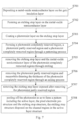
- Fig. 4 illustrates the manufacturing process for the array substrate which comprises each step as illustrated in Fig. 5 .
- Step S501 forming a pattern including a gate line 20 and a common electrode 21 on a base substrate 10.
- a metal layer for gate electrode is deposited on the base substrate 10; and the pattern including a gate line 20 and a common electrode 21 is formed through a patterning process.
- the patterning process in this application can include coating the photoresist, and masking with a mask having corresponding patterns, exposing, developing, etching and peeling off the photoresist.
- the array substrate in the embodiment of the present invention does not provide a gate electrode individually thereon, the gate electrode can
- Step S502 forming a gate insulation layer 30 on the base substrate 10 with the pattern including the gate lines 20 and the common electrode 21 formed thereon.
- Step S503 forming a pattern including an active layer 40 and a pixel electrode 50 on the base substrate 10 with the gate insulation layer 30 formed thereon, the pixel electrode 50 and the active layer 40 being disposed in the same layer.
- a metal-oxide semiconductor layer is deposited on the base substrate 10 with the gate insulation layer 30 formed thereon, and a pattern including the active layer 40 and the pixel electrode pre-structure is formed through a patterning process.
- the pixel electrode 50 is formed by performing a metallization process on the pixel electrode pre-structure.
- the metallization process comprises processing the metal-oxide semiconductor of the pixel electrode pre-structure for 30-120 min in a reducing atmosphere at 100-300°C, the reducing atmosphere comprises hydrogen or plasma containing hydrogen.
- the metallization process hydrogen is doped into the metal-oxide semiconductor, which converts the metal-oxide semiconductor into a conductor.
- Step S504 forming a pattern including a data line 60, a source electrode 61 and a drain electrode 62 on the base substrate 10 with the pattern including the pixel electrode 50 formed thereon.
- a metal layer for data line is deposited on the base substrate 10 with the pattern including the pixel electrode 50 formed thereon; and a pattern including a data line 60, a source electrode 61 and a drain electrode 62 is formed through a patterning process.
- Fig. 6 illustrates the manufacturing process of step S503 in which the metal-oxide semiconductor layer is deposited on the base substrate 10 with the gate insulation layer 30 formed thereon and the pattern including the active layer 40 and the pixel electrode pre-structure is formed through a patterning process, the manufacturing process including, for example, the steps as shown in Fig. 7 .
- Step S701 depositing a metal-oxide semiconductor layer 31 on the base substrate 10 with the gate insulation layer 30 formed thereon.
- Step S702 forming an etching stop layer 32 on the base substrate 10 with the metal-oxide semiconductor layer 31 formed thereon.
- Step S703 coating a photoresist layer 33 on the base substrate 10 with the etching stop layer 32 formed thereon.
- Step S704 a photoresist completely reserved region 331, a photoresist partly reserved region 332 and a photoresist completely removed region 333 are formed through a patterning process.
- the photoresist completely reserved region 331 corresponds to an region where a channel region in the active layer for serving as channels is located
- the photoresist partly reserved region 332 corresponds to the regions where ohmic contact regions in the active layer and the pixel electrode are located
- the photoresist completely removed region 333 correspond to rest regions.
- a grayscale mask which includes a completely opaque region, a half- transmissive regions and a completely transmissive region.
- the completely opaque region corresponds to the region where a channel region in the active layer for serving as a channel is located, the photoresist 33 is completely reserved after developing, to form the photoresist completely reserved region 331;
- the half-transmissive region corresponds to the region where ohmic contact regions in the active layer and the pixel electrode are located, the photoresist 33 is partly reserved after developing, to form the photoresist partly reserved region 332;
- the completely transmissive region corresponds to rest regions, the photoresist 33 is completely removed after developing, to form the photoresist completely removed region 333.
- Step S705 removing the etching stop layer 32 and the metal-oxide semiconductor layer 31 of the photoresist completely removed regions 333 through etching.
- Step S706 removing part of the photoresist to a form partly reserved region 332 and meanwhile thinning the thickness of the photoresist completely reserved region 331 through an ashing process.
- Step S707 removing the etching stop layer 32 which is exposed after removing the photoresist partly reserved region 332.
- Step S708 peeling off the photoresist 33 so as to form a pattern including the active layer, the pixel electrode pre-structure and the etching stop structure.
- the etching stop structure is locating above a channel region in the active layer for serving as a channel.
- the ohmic contact regions are formed by performing a metallization process on the regions where the ohmic contact regions in the active layer are located.
- the channel region is covered with the etching stop layer, making the channel region not subject to the metallization process, so as to form the active layer including the ohmic contact regions and the channel region.
- the manufacturing method of the array substrate further comprises: forming a passivation layer 70 on the base substrate 10 with the pattern including the data line 60, the source electrode 61 and the drain electrode 62 formed thereon; and forming a pattern including a transparent electrode 90 on the base substrate 10 with the passivation layer 70 formed thereon.
- the transparent electrode 90 is disposed above the data line and the common electrode 21, thus the electric field between the data line 60 and the pixel electrode 50 is shielded, which can effectively reduce crosstalk between the data line 60 and the pixel electrode 50.
- the transparent electrode 90 can also be connected to other wire layers through vias, to transmit external signals to the respective wire layers.
- a cleaning step can also be comprised before the formation of each of the film layers on the array substrate, in order to improve the quality of the array substrate.
- the embodiment of the present invention provides a manufacturing method of an array substrate comprising: forming a pattern including a gate line and a common electrode on a base substrate; forming a gate insulation layer; forming a pattern including an active layer, forming a pattern including a pixel electrode, the pixel electrode and the active layer being disposed in the same layer; and forming a pattern including a data line, a source electrode and a drain electrode.
- the storage capacitance on the array substrate as shown in Fig.
- the storage capacitance is the capacitance formed by the pixel electrode, the gate insulation layer and the common electrode, thus it can effectively increase storage capacitance and improve the display effect of the display device.
Landscapes
- Physics & Mathematics (AREA)
- Nonlinear Science (AREA)
- Mathematical Physics (AREA)
- Chemical & Material Sciences (AREA)
- Crystallography & Structural Chemistry (AREA)
- General Physics & Mathematics (AREA)
- Optics & Photonics (AREA)
- Engineering & Computer Science (AREA)
- Microelectronics & Electronic Packaging (AREA)
- Geometry (AREA)
- Liquid Crystal (AREA)
- Thin Film Transistor (AREA)
Claims (14)
- Array-Substrat, mit: einem Basis-Substrat (10), und einer Gate-Leitung (20) und einer gemeinsamen Elektrode (21), einer Gate-Isolierschicht (30), einer Aktivschicht (40) und einer Datenleitung (60), einer Source-Elektrode (61) und einer Drain-Elektrode (62), die nacheinander auf dem Basis-Substrat (10) angeordnet sind; und einer Pixel-Elektrode (50), wobeidie Gate-Leitung (20) und die gemeinsame Elektrode (21) in einer gleichen Schicht auf dem Basis-Substrat (10) bereitgestellt sind,die Gate-Elektrode (50) und die Aktivschicht (40) in einer gleichen Schicht auf der Gate-Isolierschicht (30) aus einer gleichen Metalloxid-Halbleiterschicht durch einen Metallisierungsprozess bereitgestellt sind, unddie Datenleitung (60), die Source-Elektrode (61) und die Drain-Elektrode (62) in einer gleichen Schicht auf der Pixel-Elektrode (50), der Aktivschicht (40) und der Gate-Isolierschicht (30) bereitgestellt sind, unddie gemeinsame Elektrode (21) einen Teil parallel zu der Datenleitung und einen Teil senkrecht zu der Datenleitung aufweist, unddie Pixel-Elektrode (50), die Gate-Isolierschicht (30) und die gemeinsame Elektrode (21) einen Speicherkondensator bilden.
- Array-Substrat nach Anspruch 1, wobei die Drain-Elektrode (62) ein Ende der Aktivschicht (40) angrenzend an die Pixelelektrode (50) und ein Ende der Pixelelektrode (50) angrenzend an die Aktivschicht (40) bedeckt und zwischen der Aktivschicht (40) und der Pixelelektrode (50) eingefüllt ist.
- Array-Substrat nach Anspruch 1, wobei der Metallisierungsprozess die Verarbeitung des Metall-Oxid-Halbleiters in einer reduzierenden Atmosphäre aufweist.
- Array-Substrat nach Anspruch 3, wobei das Material des Metall-Oxid-Halbleiters zur Bildung der Pixel-Elektrode (50) das gleiche ist wie das des Metall-Oxid-Halbleiters, der in der Aktivschicht (40) vorhanden ist.
- Array-Substrat nach einem der Ansprüche 1 bis 4, wobei die Aktivschicht (40) ohmsche Kontaktbereiche (41) und einen Kanalbereich (42) zwischen den ohmschen Kontaktbereichen (41) aufweist.
- Array-Substrat nach Anspruch 5, ferner mit einer Ätzstoppstruktur (80), die oben auf dem Kanalbereich (42) angeordnet ist.
- Array-Substrat nach Anspruch 5 oder 6, wobei die Aktivschicht (40) zwei der ohmschen Kontaktregionen (41) aufweist, die Source-Elektrode (61) eine der ohmschen Kontaktregionen (41) bedeckt und die Drain-Elektrode (62) eine andere der ohmschen Kontaktregionen (41) und das Ende der Pixelelektrode (50) neben der Aktivschicht (40) bedeckt und zwischen der Aktivschicht (40) und der Pixelelektrode (50) eingefüllt ist.
- Array-Substrat nach einem der Ansprüche 5 bis 7, wobei die Pixelelektrode (50) und einer der an die Pixelelektrode (50) angrenzenden ohmschen Kontaktbereiche (41) mit einem bestimmten Abstand angeordnet sind und die Drain-Elektrode (62) in dem Abstand aufgefüllt ist.
- Array-Substrat nach einem der Ansprüche 1 bis 8, ferner mit:eine Passivierungsschicht (70), die auf der Datenleitung (60), der Source-Elektrode (61) und der Drain-Elektrode (62) angeordnet ist, die in der gleichen Schicht bereitgestellt sind; undeinen ersten transparenten leitfähigen Teil, einen zweiten transparenten leitfähigen Teil und einen dritten transparenten leitfähigen Teil, die auf der Passivierungsschicht angeordnet sind und oben auf den Datenleitungen (60) und den gemeinsamen Elektroden (21) angeordnet sind, wobei der erste transparente leitfähige Teil mit der Gate-Leitung (20) über ein erstes Via verbunden ist, um die Gate-Leitungen mit Gate-Ansteuerungssignalen zu versorgen, und der zweite transparente leitfähige Teil mit der gemeinsamen Elektrode (21) über ein zweites Via verbunden ist, um die gemeinsame Elektrode (21) mit einem gemeinsamen Elektrodensignal zu versorgen, und der dritte transparente leitfähige Teil mit der Datenleitung (60) über ein drittes Via verbunden ist, um die Datenleitung (60) mit Datensignalen zu versorgen.
- Verfahren zur Herstellung eines Array-Substrats, mitBilden einer Strukturierung mit einer Gate-Leitung (20) und einer gemeinsamen Elektrode (21) auf einem Basis-Substrat (10);Bilden einer Gate-Isolierschicht (30) auf der Strukturierung der Gate-Leitungen (20) und der gemeinsamen Elektrode (21);Bilden einer Strukturierung mit einer aktiven Schicht (40) und einer Gate-Elektrode (50) auf der Gate-Isolierschicht (30) durch einen Metallisierungsprozess aus einer Metall-Oxid-Halbleiterschicht;Bilden einer Strukturierung mit einer Datenleitung (60), einer Source-Elektrode (61) und einer Drain-Elektrode (62);wobeidie Datenleitung (60), die Source-Elektrode (61) und die Drain-Elektrode (62) in einer gleichen Schicht auf der Pixel-Elektrode (50), der Aktivschicht (40) und der Gate-Isolierschicht (30) bereitgestellt werden,die Gate-Elektrode (50) und die Aktivschicht (40) in einer gleichen Schicht auf der Gate-Isolierschicht bereitgestellt werden, unddie gemeinsame Elektrode (21) einen Teil parallel zu der Datenleitung und einen Teil senkrecht zu der Datenleitung aufweist, unddie Pixel-Elektrode (50), die Gate-Isolierschicht (30) und die gemeinsame Elektrode (21) einen Speicherkondensator bilden.
- Verfahren zur Herstellung des Array-Substrats nach Anspruch 10, wobei die Metalloxid-Halbleiterschicht (31) auf der Gate-Isolierschicht (30) abgeschieden wird und eine Strukturierung mit der aktiven Schicht (40) und einer Vorstruktur der Pixel-Elektrode (50) durch einen Strukturierungsprozess der Metalloxid-Halbleiterschicht (31) gebildet wird; und
die Pixelelektrode (50) gebildet wird, indem ein Metallisierungsprozess auf der Pixelelektroden-Vorstruktur durchgeführt wird, wobei der Metallisierungsprozess eine Verarbeitung des Metalloxid-Halbleiters in einer reduzierenden Atmosphäre aufweist. - Verfahren zur Herstellung des Array-Substrats nach Anspruch 11, wobei der Metallisierungsprozess die Verarbeitung des Metalloxid-Halbleiters (31) in der Pixel-Elektroden-Vorstruktur für 30-120 min in der reduzierenden Atmosphäre bei einer Temperatur von 100°C-300°C aufweist.
- Das Herstellungsverfahren gemäß dem Array-Substrat nach einem der Ansprüche 10-12, ferner mit:Bilden einer Ätzstoppschicht (32) auf der Metall-Oxid-Halbleiterschicht (31);Aufbringen einer Fotolackschicht (33) auf die Ätzstoppschicht (32);Bilden eines vollständig vorbehaltenen Fotolackbereichs (331), eines teilweise vorbehaltenen Fotolackbereichs (332) und eines vollständig entfernten Fotolackbereichs (333) durch den Strukturierungsprozess, wobei der vollständig vorbehaltene Fotolackbereich (331) dem Bereich entspricht, in dem sich ein Kanalbereich (42) in der Aktivschicht (40) befindet, der teilweise vorbehaltene Fotolackbereich (332), der den Bereichen entspricht, in denen sich ohmsche Kontaktbereiche (41) in der zu bildenden Aktivschicht (40) und die Pixelelektrode (50) befinden, und der vollständig entfernte Fotolackbereich (333), der den übrigen Bereichen entspricht;Entfernen von Bereichen der Ätzstoppschicht (32) und der Metalloxid-Halbleiterschicht (31), die nicht von dem Fotolack (33) bedeckt sind;Entfernen des teilweise vorbehaltenen Bereichs des Fotolacks (332) und gleichzeitiges Verjüngen der Dicke des vollständig vorbehaltenen Bereichs des Fotolacks (331);Entfernen der Ätzstoppschicht (32), die nach dem Entfernen des teilweise vorbehaltenen Fotolackbereichs (332) freigelegt wurde; undAblösen des Fotolacks (33), sodass eine Strukturierung mit der aktiven Schicht (40), der Pixel-Elektroden-Vorstruktur und einer Ätzstoppstruktur gebildet wird, die ein verbleibender Teil der Ätzstoppschicht (32) ist, wobei die Ätzstoppstruktur auf dem Kanalbereich in der aktiven Schicht angeordnet ist.
- Verfahren zum Herstellen des Array-Substrats nach Anspruch 11 oder 12, wobei die ohmschen Kontaktbereiche (41) durch Ausführen des Metallisierungsprozesses auf dem Bereich in der aktiven Schicht (40) gebildet werden, um die ohmschen Kontaktbereiche (41) zu bilden, wenn die Pixelelektrode (50) durch Ausführen des Metallisierungsprozesses auf der Pixelelektroden-Vorstruktur gebildet wird, wobei der Kanalbereich (42) nicht dem Metallisierungsprozess unterworfen wird, sodass die aktive Schicht (40) die ohmschen Kontaktbereiche (41) und den Kanalbereich (42) aufweist.
Applications Claiming Priority (2)
| Application Number | Priority Date | Filing Date | Title |
|---|---|---|---|
| CN201410498785.XA CN104269414B (zh) | 2014-09-25 | 2014-09-25 | 一种阵列基板及其制作方法、显示装置 |
| PCT/CN2015/070047 WO2016045241A1 (zh) | 2014-09-25 | 2015-01-04 | 阵列基板及其制作方法、显示装置 |
Publications (3)
| Publication Number | Publication Date |
|---|---|
| EP3200231A1 EP3200231A1 (de) | 2017-08-02 |
| EP3200231A4 EP3200231A4 (de) | 2018-06-06 |
| EP3200231B1 true EP3200231B1 (de) | 2023-05-10 |
Family
ID=52160922
Family Applications (1)
| Application Number | Title | Priority Date | Filing Date |
|---|---|---|---|
| EP15804664.9A Active EP3200231B1 (de) | 2014-09-25 | 2015-01-04 | Array-substrat und herstellungsverfahren dafür |
Country Status (4)
| Country | Link |
|---|---|
| US (1) | US9786696B2 (de) |
| EP (1) | EP3200231B1 (de) |
| CN (1) | CN104269414B (de) |
| WO (1) | WO2016045241A1 (de) |
Families Citing this family (16)
| Publication number | Priority date | Publication date | Assignee | Title |
|---|---|---|---|---|
| CN104299915B (zh) * | 2014-10-21 | 2017-03-22 | 北京大学深圳研究生院 | 金属氧化物薄膜晶体管制备方法 |
| CN104810375B (zh) * | 2015-04-28 | 2018-09-04 | 合肥鑫晟光电科技有限公司 | 一种阵列基板及其制作方法和一种显示装置 |
| CN104934448B (zh) | 2015-07-10 | 2018-05-01 | 京东方科技集团股份有限公司 | 阵列基板及其制作方法、显示装置 |
| CN105514120B (zh) * | 2016-01-21 | 2018-07-20 | 京东方科技集团股份有限公司 | 一种双栅tft阵列基板及其制造方法和显示装置 |
| CN105609563B (zh) * | 2016-03-10 | 2018-11-23 | 深圳市华星光电技术有限公司 | 薄膜晶体管及其制造方法 |
| TWI582506B (zh) * | 2016-06-07 | 2017-05-11 | 友達光電股份有限公司 | 畫素陣列以及畫素結構 |
| CN106024706B (zh) * | 2016-06-22 | 2019-02-19 | 深圳市华星光电技术有限公司 | 阵列基板及其制作方法 |
| CN106024909B (zh) * | 2016-07-27 | 2021-01-26 | 京东方科技集团股份有限公司 | 薄膜晶体管及其制备方法、阵列基板和显示装置 |
| TWI656461B (zh) | 2016-07-31 | 2019-04-11 | 矽創電子股份有限公司 | 觸控顯示裝置 |
| CN106094366B (zh) * | 2016-08-23 | 2019-02-01 | 深圳市华星光电技术有限公司 | Ips型阵列基板的制作方法及ips型阵列基板 |
| US11205695B2 (en) * | 2017-12-21 | 2021-12-21 | Texas Instruments Incorporated | Method of fabricating a thick oxide feature on a semiconductor wafer |
| CN108803161B (zh) * | 2018-06-29 | 2021-07-09 | 上海天马微电子有限公司 | 显示面板、显示面板的制造方法以及显示装置 |
| CN109671723A (zh) * | 2018-12-20 | 2019-04-23 | 深圳市华星光电半导体显示技术有限公司 | 一种tft阵列基板 |
| CN110176429B (zh) * | 2019-04-08 | 2021-04-13 | 北海惠科光电技术有限公司 | 一种阵列基板的制作方法及阵列基板、显示面板 |
| CN110610949A (zh) * | 2019-10-23 | 2019-12-24 | 成都中电熊猫显示科技有限公司 | 阵列基板的制作方法及阵列基板 |
| CN112885881B (zh) * | 2021-01-21 | 2023-05-16 | 昆山国显光电有限公司 | 显示面板及其制作方法、显示装置 |
Family Cites Families (17)
| Publication number | Priority date | Publication date | Assignee | Title |
|---|---|---|---|---|
| KR950012702A (ko) * | 1993-10-21 | 1995-05-16 | 이헌조 | 박막트랜지스터 제조방법 |
| US6933528B2 (en) * | 2002-04-04 | 2005-08-23 | Nec Lcd Technologies, Ltd. | In-plane switching mode active matrix type liquid crystal display device and method of fabricating the same |
| KR100916603B1 (ko) * | 2002-12-09 | 2009-09-14 | 엘지디스플레이 주식회사 | 액정표시장치용 어레이기판 제조방법 |
| CN101887898A (zh) * | 2009-05-15 | 2010-11-17 | 北京京东方光电科技有限公司 | Tft-lcd阵列基板及其制造方法 |
| TWI396314B (zh) * | 2009-07-27 | 2013-05-11 | Au Optronics Corp | 畫素結構、有機電激發光顯示單元及其製造方法 |
| US20110085121A1 (en) * | 2009-10-08 | 2011-04-14 | Hydis Technologies Co., Ltd. | Fringe Field Switching Mode Liquid Crystal Display Device and Method of Fabricating the Same |
| CN102156368A (zh) * | 2011-01-18 | 2011-08-17 | 京东方科技集团股份有限公司 | 薄膜晶体管液晶显示阵列基板及其制造方法 |
| CN102629577B (zh) | 2011-09-29 | 2013-11-13 | 京东方科技集团股份有限公司 | 一种tft阵列基板及其制造方法和显示装置 |
| KR101960533B1 (ko) * | 2011-11-10 | 2019-03-21 | 엘지디스플레이 주식회사 | 금속 산화물 반도체를 포함하는 박막 트랜지스터 기판 및 그 제조 방법 |
| CN102790012A (zh) * | 2012-07-20 | 2012-11-21 | 京东方科技集团股份有限公司 | 阵列基板的制造方法及阵列基板、显示装置 |
| CN102810558B (zh) * | 2012-08-07 | 2014-10-15 | 京东方科技集团股份有限公司 | 薄膜晶体管、阵列基板及其制作方法和液晶显示器 |
| CN103077944B (zh) * | 2013-01-18 | 2016-03-09 | 京东方科技集团股份有限公司 | 显示装置、阵列基板及其制作方法 |
| CN103984170A (zh) * | 2013-02-19 | 2014-08-13 | 上海天马微电子有限公司 | 阵列基板及其制造方法、液晶显示器 |
| CN103474439B (zh) * | 2013-09-26 | 2016-08-24 | 合肥京东方光电科技有限公司 | 一种显示装置、阵列基板及其制作方法 |
| CN103605241A (zh) * | 2013-11-21 | 2014-02-26 | 深圳市华星光电技术有限公司 | 一种液晶显示面板 |
| CN103715094B (zh) * | 2013-12-27 | 2017-02-01 | 京东方科技集团股份有限公司 | 薄膜晶体管及制备方法、阵列基板及制备方法、显示装置 |
| CN103744245A (zh) * | 2013-12-31 | 2014-04-23 | 深圳市华星光电技术有限公司 | 一种液晶显示器阵列基板及相应的液晶显示器 |
-
2014
- 2014-09-25 CN CN201410498785.XA patent/CN104269414B/zh active Active
-
2015
- 2015-01-04 EP EP15804664.9A patent/EP3200231B1/de active Active
- 2015-01-04 US US14/769,221 patent/US9786696B2/en not_active Expired - Fee Related
- 2015-01-04 WO PCT/CN2015/070047 patent/WO2016045241A1/zh not_active Ceased
Also Published As
| Publication number | Publication date |
|---|---|
| EP3200231A1 (de) | 2017-08-02 |
| US9786696B2 (en) | 2017-10-10 |
| EP3200231A4 (de) | 2018-06-06 |
| WO2016045241A1 (zh) | 2016-03-31 |
| CN104269414B (zh) | 2018-03-09 |
| CN104269414A (zh) | 2015-01-07 |
| US20160268317A1 (en) | 2016-09-15 |
Similar Documents
| Publication | Publication Date | Title |
|---|---|---|
| EP3200231B1 (de) | Array-substrat und herstellungsverfahren dafür | |
| EP2876676B1 (de) | Verfahren zur herstellung eines arraysubstrats sowie arraysubstrat und anzeigevorrichtung | |
| US9865622B2 (en) | Array substrate and a method for manufacturing the same | |
| CN110137084B (zh) | 薄膜晶体管及其制备方法、电子装置基板及电子装置 | |
| US10998353B2 (en) | Array substrate and display device | |
| US20170285430A1 (en) | Array Substrate and Manufacturing Method Thereof, Display Panel and Display Device | |
| US10622483B2 (en) | Thin film transistor, array substrate and display device | |
| JP6359650B2 (ja) | アレイ基板、表示装置及びアレイ基板の製作方法 | |
| TW201232629A (en) | Flat panel display apparatus and method of manufacturing the same | |
| US9893098B2 (en) | Array substrate and fabrication method thereof, and display device | |
| US20140134809A1 (en) | Method for manufacturing fan-out lines on array substrate | |
| EP3602614A1 (de) | Dünnschichttransistor und anzeigesubstrat, herstellungsverfahren dafür und anzeigevorrichtung | |
| US9971437B2 (en) | Array substrate, display device having the same, and manufacturing method thereof | |
| EP3159734B1 (de) | Arraysubstrat und herstellungsverfahren dafür sowie anzeigevorrichtung | |
| US10797087B2 (en) | Array substrate manufacturing method thereof and display device | |
| EP2731127B1 (de) | Tft-array-substrat, herstellungsverfahren dafür und anzeigevorrichtung | |
| US10204928B2 (en) | Display substrate, liquid crystal display panel and display apparatus having the same, and fabricating method thereof | |
| US9543325B2 (en) | Array substrate and manufacturing method thereof, liquid crystal display panel and display device | |
| US10833107B2 (en) | Thin film transistor, manufacturing method therefor, array substrate and display device | |
| EP2983204B1 (de) | Anzeigevorrichtung und verfahren zu deren herstellung | |
| CN103474439B (zh) | 一种显示装置、阵列基板及其制作方法 | |
| CN103413834A (zh) | 一种薄膜晶体管及其制作方法、阵列基板及显示装置 | |
| US9799688B2 (en) | Array substrate with uniform charge distribution, method for manufacturing the same and display device | |
| EP3163620B1 (de) | Niedrigtemperatur-polysilicium-dünnfilmtransistorarraysubstrat und herstellungsverfahren dafür sowie anzeigevorrichtung damit | |
| CN106856199B (zh) | 显示面板及其制造方法 |
Legal Events
| Date | Code | Title | Description |
|---|---|---|---|
| PUAI | Public reference made under article 153(3) epc to a published international application that has entered the european phase |
Free format text: ORIGINAL CODE: 0009012 |
|
| STAA | Information on the status of an ep patent application or granted ep patent |
Free format text: STATUS: REQUEST FOR EXAMINATION WAS MADE |
|
| 17P | Request for examination filed |
Effective date: 20151215 |
|
| AK | Designated contracting states |
Kind code of ref document: A1 Designated state(s): AL AT BE BG CH CY CZ DE DK EE ES FI FR GB GR HR HU IE IS IT LI LT LU LV MC MK MT NL NO PL PT RO RS SE SI SK SM TR |
|
| AX | Request for extension of the european patent |
Extension state: BA ME |
|
| DAX | Request for extension of the european patent (deleted) | ||
| RIC1 | Information provided on ipc code assigned before grant |
Ipc: H01L 27/12 20060101AFI20180425BHEP Ipc: H01L 21/77 20170101ALI20180425BHEP Ipc: G02F 1/1362 20060101ALI20180425BHEP Ipc: G02F 1/1343 20060101ALI20180425BHEP |
|
| A4 | Supplementary search report drawn up and despatched |
Effective date: 20180507 |
|
| STAA | Information on the status of an ep patent application or granted ep patent |
Free format text: STATUS: EXAMINATION IS IN PROGRESS |
|
| 17Q | First examination report despatched |
Effective date: 20210225 |
|
| GRAP | Despatch of communication of intention to grant a patent |
Free format text: ORIGINAL CODE: EPIDOSNIGR1 |
|
| STAA | Information on the status of an ep patent application or granted ep patent |
Free format text: STATUS: GRANT OF PATENT IS INTENDED |
|
| RIC1 | Information provided on ipc code assigned before grant |
Ipc: G02F 1/1368 20060101ALI20221221BHEP Ipc: G02F 1/1362 20060101ALI20221221BHEP Ipc: G02F 1/1343 20060101ALI20221221BHEP Ipc: H01L 21/77 20170101ALI20221221BHEP Ipc: H01L 27/12 20060101AFI20221221BHEP |
|
| INTG | Intention to grant announced |
Effective date: 20230125 |
|
| GRAS | Grant fee paid |
Free format text: ORIGINAL CODE: EPIDOSNIGR3 |
|
| GRAA | (expected) grant |
Free format text: ORIGINAL CODE: 0009210 |
|
| STAA | Information on the status of an ep patent application or granted ep patent |
Free format text: STATUS: THE PATENT HAS BEEN GRANTED |
|
| AK | Designated contracting states |
Kind code of ref document: B1 Designated state(s): AL AT BE BG CH CY CZ DE DK EE ES FI FR GB GR HR HU IE IS IT LI LT LU LV MC MK MT NL NO PL PT RO RS SE SI SK SM TR |
|
| REG | Reference to a national code |
Ref country code: GB Ref legal event code: FG4D |
|
| REG | Reference to a national code |
Ref country code: AT Ref legal event code: REF Ref document number: 1567574 Country of ref document: AT Kind code of ref document: T Effective date: 20230515 Ref country code: CH Ref legal event code: EP |
|
| REG | Reference to a national code |
Ref country code: DE Ref legal event code: R096 Ref document number: 602015083540 Country of ref document: DE |
|
| REG | Reference to a national code |
Ref country code: IE Ref legal event code: FG4D |
|
| REG | Reference to a national code |
Ref country code: LT Ref legal event code: MG9D |
|
| REG | Reference to a national code |
Ref country code: NL Ref legal event code: MP Effective date: 20230510 |
|
| REG | Reference to a national code |
Ref country code: AT Ref legal event code: MK05 Ref document number: 1567574 Country of ref document: AT Kind code of ref document: T Effective date: 20230510 |
|
| PG25 | Lapsed in a contracting state [announced via postgrant information from national office to epo] |
Ref country code: SE Free format text: LAPSE BECAUSE OF FAILURE TO SUBMIT A TRANSLATION OF THE DESCRIPTION OR TO PAY THE FEE WITHIN THE PRESCRIBED TIME-LIMIT Effective date: 20230510 Ref country code: PT Free format text: LAPSE BECAUSE OF FAILURE TO SUBMIT A TRANSLATION OF THE DESCRIPTION OR TO PAY THE FEE WITHIN THE PRESCRIBED TIME-LIMIT Effective date: 20230911 Ref country code: NO Free format text: LAPSE BECAUSE OF FAILURE TO SUBMIT A TRANSLATION OF THE DESCRIPTION OR TO PAY THE FEE WITHIN THE PRESCRIBED TIME-LIMIT Effective date: 20230810 Ref country code: NL Free format text: LAPSE BECAUSE OF FAILURE TO SUBMIT A TRANSLATION OF THE DESCRIPTION OR TO PAY THE FEE WITHIN THE PRESCRIBED TIME-LIMIT Effective date: 20230510 Ref country code: ES Free format text: LAPSE BECAUSE OF FAILURE TO SUBMIT A TRANSLATION OF THE DESCRIPTION OR TO PAY THE FEE WITHIN THE PRESCRIBED TIME-LIMIT Effective date: 20230510 Ref country code: AT Free format text: LAPSE BECAUSE OF FAILURE TO SUBMIT A TRANSLATION OF THE DESCRIPTION OR TO PAY THE FEE WITHIN THE PRESCRIBED TIME-LIMIT Effective date: 20230510 |
|
| PG25 | Lapsed in a contracting state [announced via postgrant information from national office to epo] |
Ref country code: RS Free format text: LAPSE BECAUSE OF FAILURE TO SUBMIT A TRANSLATION OF THE DESCRIPTION OR TO PAY THE FEE WITHIN THE PRESCRIBED TIME-LIMIT Effective date: 20230510 Ref country code: PL Free format text: LAPSE BECAUSE OF FAILURE TO SUBMIT A TRANSLATION OF THE DESCRIPTION OR TO PAY THE FEE WITHIN THE PRESCRIBED TIME-LIMIT Effective date: 20230510 Ref country code: LV Free format text: LAPSE BECAUSE OF FAILURE TO SUBMIT A TRANSLATION OF THE DESCRIPTION OR TO PAY THE FEE WITHIN THE PRESCRIBED TIME-LIMIT Effective date: 20230510 Ref country code: LT Free format text: LAPSE BECAUSE OF FAILURE TO SUBMIT A TRANSLATION OF THE DESCRIPTION OR TO PAY THE FEE WITHIN THE PRESCRIBED TIME-LIMIT Effective date: 20230510 Ref country code: IS Free format text: LAPSE BECAUSE OF FAILURE TO SUBMIT A TRANSLATION OF THE DESCRIPTION OR TO PAY THE FEE WITHIN THE PRESCRIBED TIME-LIMIT Effective date: 20230910 Ref country code: HR Free format text: LAPSE BECAUSE OF FAILURE TO SUBMIT A TRANSLATION OF THE DESCRIPTION OR TO PAY THE FEE WITHIN THE PRESCRIBED TIME-LIMIT Effective date: 20230510 Ref country code: GR Free format text: LAPSE BECAUSE OF FAILURE TO SUBMIT A TRANSLATION OF THE DESCRIPTION OR TO PAY THE FEE WITHIN THE PRESCRIBED TIME-LIMIT Effective date: 20230811 |
|
| PG25 | Lapsed in a contracting state [announced via postgrant information from national office to epo] |
Ref country code: FI Free format text: LAPSE BECAUSE OF FAILURE TO SUBMIT A TRANSLATION OF THE DESCRIPTION OR TO PAY THE FEE WITHIN THE PRESCRIBED TIME-LIMIT Effective date: 20230510 |
|
| PG25 | Lapsed in a contracting state [announced via postgrant information from national office to epo] |
Ref country code: SK Free format text: LAPSE BECAUSE OF FAILURE TO SUBMIT A TRANSLATION OF THE DESCRIPTION OR TO PAY THE FEE WITHIN THE PRESCRIBED TIME-LIMIT Effective date: 20230510 |
|
| PG25 | Lapsed in a contracting state [announced via postgrant information from national office to epo] |
Ref country code: SM Free format text: LAPSE BECAUSE OF FAILURE TO SUBMIT A TRANSLATION OF THE DESCRIPTION OR TO PAY THE FEE WITHIN THE PRESCRIBED TIME-LIMIT Effective date: 20230510 Ref country code: SK Free format text: LAPSE BECAUSE OF FAILURE TO SUBMIT A TRANSLATION OF THE DESCRIPTION OR TO PAY THE FEE WITHIN THE PRESCRIBED TIME-LIMIT Effective date: 20230510 Ref country code: RO Free format text: LAPSE BECAUSE OF FAILURE TO SUBMIT A TRANSLATION OF THE DESCRIPTION OR TO PAY THE FEE WITHIN THE PRESCRIBED TIME-LIMIT Effective date: 20230510 Ref country code: EE Free format text: LAPSE BECAUSE OF FAILURE TO SUBMIT A TRANSLATION OF THE DESCRIPTION OR TO PAY THE FEE WITHIN THE PRESCRIBED TIME-LIMIT Effective date: 20230510 Ref country code: DK Free format text: LAPSE BECAUSE OF FAILURE TO SUBMIT A TRANSLATION OF THE DESCRIPTION OR TO PAY THE FEE WITHIN THE PRESCRIBED TIME-LIMIT Effective date: 20230510 Ref country code: CZ Free format text: LAPSE BECAUSE OF FAILURE TO SUBMIT A TRANSLATION OF THE DESCRIPTION OR TO PAY THE FEE WITHIN THE PRESCRIBED TIME-LIMIT Effective date: 20230510 |
|
| REG | Reference to a national code |
Ref country code: DE Ref legal event code: R097 Ref document number: 602015083540 Country of ref document: DE |
|
| PLBE | No opposition filed within time limit |
Free format text: ORIGINAL CODE: 0009261 |
|
| STAA | Information on the status of an ep patent application or granted ep patent |
Free format text: STATUS: NO OPPOSITION FILED WITHIN TIME LIMIT |
|
| 26N | No opposition filed |
Effective date: 20240213 |
|
| PG25 | Lapsed in a contracting state [announced via postgrant information from national office to epo] |
Ref country code: SI Free format text: LAPSE BECAUSE OF FAILURE TO SUBMIT A TRANSLATION OF THE DESCRIPTION OR TO PAY THE FEE WITHIN THE PRESCRIBED TIME-LIMIT Effective date: 20230510 |
|
| PG25 | Lapsed in a contracting state [announced via postgrant information from national office to epo] |
Ref country code: SI Free format text: LAPSE BECAUSE OF FAILURE TO SUBMIT A TRANSLATION OF THE DESCRIPTION OR TO PAY THE FEE WITHIN THE PRESCRIBED TIME-LIMIT Effective date: 20230510 Ref country code: IT Free format text: LAPSE BECAUSE OF FAILURE TO SUBMIT A TRANSLATION OF THE DESCRIPTION OR TO PAY THE FEE WITHIN THE PRESCRIBED TIME-LIMIT Effective date: 20230510 |
|
| PG25 | Lapsed in a contracting state [announced via postgrant information from national office to epo] |
Ref country code: MC Free format text: LAPSE BECAUSE OF FAILURE TO SUBMIT A TRANSLATION OF THE DESCRIPTION OR TO PAY THE FEE WITHIN THE PRESCRIBED TIME-LIMIT Effective date: 20230510 |
|
| PG25 | Lapsed in a contracting state [announced via postgrant information from national office to epo] |
Ref country code: MC Free format text: LAPSE BECAUSE OF FAILURE TO SUBMIT A TRANSLATION OF THE DESCRIPTION OR TO PAY THE FEE WITHIN THE PRESCRIBED TIME-LIMIT Effective date: 20230510 |
|
| REG | Reference to a national code |
Ref country code: CH Ref legal event code: PL |
|
| PG25 | Lapsed in a contracting state [announced via postgrant information from national office to epo] |
Ref country code: LU Free format text: LAPSE BECAUSE OF NON-PAYMENT OF DUE FEES Effective date: 20240104 |
|
| GBPC | Gb: european patent ceased through non-payment of renewal fee |
Effective date: 20240104 |
|
| PG25 | Lapsed in a contracting state [announced via postgrant information from national office to epo] |
Ref country code: LU Free format text: LAPSE BECAUSE OF NON-PAYMENT OF DUE FEES Effective date: 20240104 |
|
| PG25 | Lapsed in a contracting state [announced via postgrant information from national office to epo] |
Ref country code: GB Free format text: LAPSE BECAUSE OF NON-PAYMENT OF DUE FEES Effective date: 20240104 |
|
| PG25 | Lapsed in a contracting state [announced via postgrant information from national office to epo] |
Ref country code: BE Free format text: LAPSE BECAUSE OF NON-PAYMENT OF DUE FEES Effective date: 20240131 |
|
| PG25 | Lapsed in a contracting state [announced via postgrant information from national office to epo] |
Ref country code: FR Free format text: LAPSE BECAUSE OF NON-PAYMENT OF DUE FEES Effective date: 20240131 |
|
| PG25 | Lapsed in a contracting state [announced via postgrant information from national office to epo] |
Ref country code: CH Free format text: LAPSE BECAUSE OF NON-PAYMENT OF DUE FEES Effective date: 20240131 |
|
| PG25 | Lapsed in a contracting state [announced via postgrant information from national office to epo] |
Ref country code: GB Free format text: LAPSE BECAUSE OF NON-PAYMENT OF DUE FEES Effective date: 20240104 Ref country code: FR Free format text: LAPSE BECAUSE OF NON-PAYMENT OF DUE FEES Effective date: 20240131 Ref country code: CH Free format text: LAPSE BECAUSE OF NON-PAYMENT OF DUE FEES Effective date: 20240131 Ref country code: BE Free format text: LAPSE BECAUSE OF NON-PAYMENT OF DUE FEES Effective date: 20240131 |
|
| REG | Reference to a national code |
Ref country code: BE Ref legal event code: MM Effective date: 20240131 |
|
| PG25 | Lapsed in a contracting state [announced via postgrant information from national office to epo] |
Ref country code: BG Free format text: LAPSE BECAUSE OF FAILURE TO SUBMIT A TRANSLATION OF THE DESCRIPTION OR TO PAY THE FEE WITHIN THE PRESCRIBED TIME-LIMIT Effective date: 20230510 |
|
| REG | Reference to a national code |
Ref country code: DE Ref legal event code: R079 Ref document number: 602015083540 Country of ref document: DE Free format text: PREVIOUS MAIN CLASS: H01L0027120000 Ipc: H10D0086000000 |
|
| PG25 | Lapsed in a contracting state [announced via postgrant information from national office to epo] |
Ref country code: BG Free format text: LAPSE BECAUSE OF FAILURE TO SUBMIT A TRANSLATION OF THE DESCRIPTION OR TO PAY THE FEE WITHIN THE PRESCRIBED TIME-LIMIT Effective date: 20230510 |
|
| PG25 | Lapsed in a contracting state [announced via postgrant information from national office to epo] |
Ref country code: IE Free format text: LAPSE BECAUSE OF NON-PAYMENT OF DUE FEES Effective date: 20240104 |
|
| PG25 | Lapsed in a contracting state [announced via postgrant information from national office to epo] |
Ref country code: IE Free format text: LAPSE BECAUSE OF NON-PAYMENT OF DUE FEES Effective date: 20240104 |
|
| PGFP | Annual fee paid to national office [announced via postgrant information from national office to epo] |
Ref country code: DE Payment date: 20250121 Year of fee payment: 11 |
|
| PG25 | Lapsed in a contracting state [announced via postgrant information from national office to epo] |
Ref country code: CY Free format text: LAPSE BECAUSE OF FAILURE TO SUBMIT A TRANSLATION OF THE DESCRIPTION OR TO PAY THE FEE WITHIN THE PRESCRIBED TIME-LIMIT; INVALID AB INITIO Effective date: 20150104 |
|
| PG25 | Lapsed in a contracting state [announced via postgrant information from national office to epo] |
Ref country code: HU Free format text: LAPSE BECAUSE OF FAILURE TO SUBMIT A TRANSLATION OF THE DESCRIPTION OR TO PAY THE FEE WITHIN THE PRESCRIBED TIME-LIMIT; INVALID AB INITIO Effective date: 20150104 |
|
| PG25 | Lapsed in a contracting state [announced via postgrant information from national office to epo] |
Ref country code: TR Free format text: LAPSE BECAUSE OF FAILURE TO SUBMIT A TRANSLATION OF THE DESCRIPTION OR TO PAY THE FEE WITHIN THE PRESCRIBED TIME-LIMIT Effective date: 20230510 |