EP3196945B2 - Solarzelle - Google Patents
Solarzelle Download PDFInfo
- Publication number
- EP3196945B2 EP3196945B2 EP17152171.9A EP17152171A EP3196945B2 EP 3196945 B2 EP3196945 B2 EP 3196945B2 EP 17152171 A EP17152171 A EP 17152171A EP 3196945 B2 EP3196945 B2 EP 3196945B2
- Authority
- EP
- European Patent Office
- Prior art keywords
- semiconductor substrate
- transparent conductive
- layer
- conductive layer
- doped layer
- Prior art date
- Legal status (The legal status is an assumption and is not a legal conclusion. Google has not performed a legal analysis and makes no representation as to the accuracy of the status listed.)
- Active
Links
Images


Classifications
-
- B—PERFORMING OPERATIONS; TRANSPORTING
- B29—WORKING OF PLASTICS; WORKING OF SUBSTANCES IN A PLASTIC STATE IN GENERAL
- B29C—SHAPING OR JOINING OF PLASTICS; SHAPING OF MATERIAL IN A PLASTIC STATE, NOT OTHERWISE PROVIDED FOR; AFTER-TREATMENT OF THE SHAPED PRODUCTS, e.g. REPAIRING
- B29C64/00—Additive manufacturing, i.e. manufacturing of three-dimensional [3D] objects by additive deposition, additive agglomeration or additive layering, e.g. by 3D printing, stereolithography or selective laser sintering
- B29C64/20—Apparatus for additive manufacturing; Details thereof or accessories therefor
- B29C64/205—Means for applying layers
- B29C64/209—Heads; Nozzles
-
- B—PERFORMING OPERATIONS; TRANSPORTING
- B29—WORKING OF PLASTICS; WORKING OF SUBSTANCES IN A PLASTIC STATE IN GENERAL
- B29C—SHAPING OR JOINING OF PLASTICS; SHAPING OF MATERIAL IN A PLASTIC STATE, NOT OTHERWISE PROVIDED FOR; AFTER-TREATMENT OF THE SHAPED PRODUCTS, e.g. REPAIRING
- B29C64/00—Additive manufacturing, i.e. manufacturing of three-dimensional [3D] objects by additive deposition, additive agglomeration or additive layering, e.g. by 3D printing, stereolithography or selective laser sintering
- B29C64/10—Processes of additive manufacturing
- B29C64/106—Processes of additive manufacturing using only liquids or viscous materials, e.g. depositing a continuous bead of viscous material
-
- B—PERFORMING OPERATIONS; TRANSPORTING
- B33—ADDITIVE MANUFACTURING TECHNOLOGY
- B33Y—ADDITIVE MANUFACTURING, i.e. MANUFACTURING OF THREE-DIMENSIONAL [3D] OBJECTS BY ADDITIVE DEPOSITION, ADDITIVE AGGLOMERATION OR ADDITIVE LAYERING, e.g. BY 3D PRINTING, STEREOLITHOGRAPHY OR SELECTIVE LASER SINTERING
- B33Y40/00—Auxiliary operations or equipment, e.g. for material handling
-
- H—ELECTRICITY
- H02—GENERATION; CONVERSION OR DISTRIBUTION OF ELECTRIC POWER
- H02S—GENERATION OF ELECTRIC POWER BY CONVERSION OF INFRARED RADIATION, VISIBLE LIGHT OR ULTRAVIOLET LIGHT, e.g. USING PHOTOVOLTAIC [PV] MODULES
- H02S20/00—Supporting structures for PV modules
-
- H—ELECTRICITY
- H02—GENERATION; CONVERSION OR DISTRIBUTION OF ELECTRIC POWER
- H02S—GENERATION OF ELECTRIC POWER BY CONVERSION OF INFRARED RADIATION, VISIBLE LIGHT OR ULTRAVIOLET LIGHT, e.g. USING PHOTOVOLTAIC [PV] MODULES
- H02S30/00—Structural details of PV modules other than those related to light conversion
- H02S30/20—Collapsible or foldable PV modules
-
- H—ELECTRICITY
- H10—SEMICONDUCTOR DEVICES; ELECTRIC SOLID-STATE DEVICES NOT OTHERWISE PROVIDED FOR
- H10F—INORGANIC SEMICONDUCTOR DEVICES SENSITIVE TO INFRARED RADIATION, LIGHT, ELECTROMAGNETIC RADIATION OF SHORTER WAVELENGTH OR CORPUSCULAR RADIATION
- H10F10/00—Individual photovoltaic cells, e.g. solar cells
- H10F10/10—Individual photovoltaic cells, e.g. solar cells having potential barriers
- H10F10/16—Photovoltaic cells having only PN heterojunction potential barriers
- H10F10/164—Photovoltaic cells having only PN heterojunction potential barriers comprising heterojunctions with Group IV materials, e.g. ITO/Si or GaAs/SiGe photovoltaic cells
- H10F10/165—Photovoltaic cells having only PN heterojunction potential barriers comprising heterojunctions with Group IV materials, e.g. ITO/Si or GaAs/SiGe photovoltaic cells the heterojunctions being Group IV-IV heterojunctions, e.g. Si/Ge, SiGe/Si or Si/SiC photovoltaic cells
- H10F10/166—Photovoltaic cells having only PN heterojunction potential barriers comprising heterojunctions with Group IV materials, e.g. ITO/Si or GaAs/SiGe photovoltaic cells the heterojunctions being Group IV-IV heterojunctions, e.g. Si/Ge, SiGe/Si or Si/SiC photovoltaic cells the Group IV-IV heterojunctions being heterojunctions of crystalline and amorphous materials, e.g. silicon heterojunction [SHJ] photovoltaic cells
-
- H—ELECTRICITY
- H10—SEMICONDUCTOR DEVICES; ELECTRIC SOLID-STATE DEVICES NOT OTHERWISE PROVIDED FOR
- H10F—INORGANIC SEMICONDUCTOR DEVICES SENSITIVE TO INFRARED RADIATION, LIGHT, ELECTROMAGNETIC RADIATION OF SHORTER WAVELENGTH OR CORPUSCULAR RADIATION
- H10F19/00—Integrated devices, or assemblies of multiple devices, comprising at least one photovoltaic cell covered by group H10F10/00, e.g. photovoltaic modules
- H10F19/80—Encapsulations or containers for integrated devices, or assemblies of multiple devices, having photovoltaic cells
-
- H—ELECTRICITY
- H10—SEMICONDUCTOR DEVICES; ELECTRIC SOLID-STATE DEVICES NOT OTHERWISE PROVIDED FOR
- H10F—INORGANIC SEMICONDUCTOR DEVICES SENSITIVE TO INFRARED RADIATION, LIGHT, ELECTROMAGNETIC RADIATION OF SHORTER WAVELENGTH OR CORPUSCULAR RADIATION
- H10F71/00—Manufacture or treatment of devices covered by this subclass
-
- H—ELECTRICITY
- H10—SEMICONDUCTOR DEVICES; ELECTRIC SOLID-STATE DEVICES NOT OTHERWISE PROVIDED FOR
- H10F—INORGANIC SEMICONDUCTOR DEVICES SENSITIVE TO INFRARED RADIATION, LIGHT, ELECTROMAGNETIC RADIATION OF SHORTER WAVELENGTH OR CORPUSCULAR RADIATION
- H10F77/00—Constructional details of devices covered by this subclass
- H10F77/20—Electrodes
- H10F77/206—Electrodes for devices having potential barriers
- H10F77/211—Electrodes for devices having potential barriers for photovoltaic cells
- H10F77/215—Geometries of grid contacts
-
- H—ELECTRICITY
- H10—SEMICONDUCTOR DEVICES; ELECTRIC SOLID-STATE DEVICES NOT OTHERWISE PROVIDED FOR
- H10F—INORGANIC SEMICONDUCTOR DEVICES SENSITIVE TO INFRARED RADIATION, LIGHT, ELECTROMAGNETIC RADIATION OF SHORTER WAVELENGTH OR CORPUSCULAR RADIATION
- H10F77/00—Constructional details of devices covered by this subclass
- H10F77/20—Electrodes
- H10F77/206—Electrodes for devices having potential barriers
- H10F77/211—Electrodes for devices having potential barriers for photovoltaic cells
- H10F77/219—Arrangements for electrodes of back-contact photovoltaic cells
-
- H—ELECTRICITY
- H10—SEMICONDUCTOR DEVICES; ELECTRIC SOLID-STATE DEVICES NOT OTHERWISE PROVIDED FOR
- H10F—INORGANIC SEMICONDUCTOR DEVICES SENSITIVE TO INFRARED RADIATION, LIGHT, ELECTROMAGNETIC RADIATION OF SHORTER WAVELENGTH OR CORPUSCULAR RADIATION
- H10F77/00—Constructional details of devices covered by this subclass
- H10F77/20—Electrodes
- H10F77/244—Electrodes made of transparent conductive layers, e.g. transparent conductive oxide [TCO] layers
-
- H—ELECTRICITY
- H10—SEMICONDUCTOR DEVICES; ELECTRIC SOLID-STATE DEVICES NOT OTHERWISE PROVIDED FOR
- H10F—INORGANIC SEMICONDUCTOR DEVICES SENSITIVE TO INFRARED RADIATION, LIGHT, ELECTROMAGNETIC RADIATION OF SHORTER WAVELENGTH OR CORPUSCULAR RADIATION
- H10F77/00—Constructional details of devices covered by this subclass
- H10F77/30—Coatings
- H10F77/306—Coatings for devices having potential barriers
- H10F77/311—Coatings for devices having potential barriers for photovoltaic cells
- H10F77/315—Coatings for devices having potential barriers for photovoltaic cells the coatings being antireflective or having enhancing optical properties
-
- H—ELECTRICITY
- H10—SEMICONDUCTOR DEVICES; ELECTRIC SOLID-STATE DEVICES NOT OTHERWISE PROVIDED FOR
- H10F—INORGANIC SEMICONDUCTOR DEVICES SENSITIVE TO INFRARED RADIATION, LIGHT, ELECTROMAGNETIC RADIATION OF SHORTER WAVELENGTH OR CORPUSCULAR RADIATION
- H10F77/00—Constructional details of devices covered by this subclass
- H10F77/93—Interconnections
- H10F77/933—Interconnections for devices having potential barriers
- H10F77/935—Interconnections for devices having potential barriers for photovoltaic devices or modules
-
- Y—GENERAL TAGGING OF NEW TECHNOLOGICAL DEVELOPMENTS; GENERAL TAGGING OF CROSS-SECTIONAL TECHNOLOGIES SPANNING OVER SEVERAL SECTIONS OF THE IPC; TECHNICAL SUBJECTS COVERED BY FORMER USPC CROSS-REFERENCE ART COLLECTIONS [XRACs] AND DIGESTS
- Y02—TECHNOLOGIES OR APPLICATIONS FOR MITIGATION OR ADAPTATION AGAINST CLIMATE CHANGE
- Y02E—REDUCTION OF GREENHOUSE GAS [GHG] EMISSIONS, RELATED TO ENERGY GENERATION, TRANSMISSION OR DISTRIBUTION
- Y02E10/00—Energy generation through renewable energy sources
- Y02E10/50—Photovoltaic [PV] energy
Definitions
- Embodiments of the invention relate to a solar cell, and more particularly to a hetero-junction solar cell.
- hetero-junction solar cells include solar cells using intrinsic-amorphous silicon (i-a-Si) as a passivation layer, and solar cells using a thin tunnel oxide layer as a passivation layer.
- i-a-Si intrinsic-amorphous silicon
- the hetero-junction solar cells are formed on front and back surfaces of a semiconductor substrate for a solar cell and include a transparent conductive oxide (TCO) layer that performs an optical function (for example, a function of an anti-reflection layer and a reflection layer) and an electrical function (for example, a contact function with a metal electrode).
- TCO transparent conductive oxide
- EP 2 682 990 A1 discloses a heterojunction solar cell with a front layer and a back layer provided on the front and back surfaces of a semiconductor substrate, respectively, and overlapping each other on the side surface of the semiconductor substrate.
- the heterojunction solar cell also comprises an electrically conductive back coating which is formed with a distance to the edge of the semiconductor substrate and a front anti-reflection coating which covers the whole surface of the front layer and may also extend to the side surface of the semiconductor substrate.
- KR 2012 0104846 A discloses a solar battery and a manufacturing method thereof in which a first conductive layer is formed on a first semiconductor layer, a first electrode is formed on the first conductive layer, a second semiconductor layer is formed on the other side of the semiconductor wafer, the second semiconductor layer has different polarity with the first semiconductor layer, a second conductive layer is formed on the second semiconductor layer, a second electrode is formed on the second conductive layer, and the first conductive layer and the second conductive layer are formed in order not to contact each other in a side of the semiconductor wafer.
- EP 1 696 492 A1 discloses a photovoltaic cell in which a first electrode layer is formed so as to cover a region extending to an outer periphery of a semiconductor.
- An object of the invention is to provide a high-efficiency solar cell.
- a width in a first direction of the front transparent conductive layer may be equal to or greater than a width in the first direction of the semiconductor substrate.
- a region where the front transparent conductive layer is not formed is locally located in a part of the edge region of the front surface of the semiconductor substrate.
- a plurality of regions where the front transparent conductive layer is not formed may be spaced apart from each other.
- a width in the first direction and a width in a second direction of the back transparent conductive layer may be less than the width in the first direction and a width in the second direction of the semiconductor substrate, respectively.
- the back transparent conductive layer may be not formed in an edge region of the back surface of the semiconductor substrate.
- a region where the back transparent conductive layer is not formed is continuously formed along an edge of the semiconductor substrate.
- each of the front surface and the back surface of the semiconductor substrate Includes an edge region that is continuously formed from an edge of the semiconductor substrate to inside of the semiconductor substrate along the edge and a center region that is a remaining region except for the edge region.
- the front transparent conductive layer is formed in the center region and a remaining edge region except for a non-formed portion formed discontinuously in a part of the edge region of the front surface.
- the back transparent conductive layer is formed only in the center region except for the edge region of the back surface.
- the physical connection or physical contact between the front transparent conductive layer and the back transparent conductive layer is completely prevented and the size of the front transparent conductive layer located on the front surface of the semiconductor substrate on which light is incident can be maximized.
- the back collector electrode includes a plurality of second finger electrodes extending in the first direction and at least one second bus bar electrode extending in the second direction and physically connected to the plurality of second finger electrodes, or include a sheet electrode which covers entirely the back surface of the back transparent conductive layer.
- the non-formed portion is located at both ends of the at least one first bus bar electrode.
- a width in the first direction of the both ends of the at least one first bus bar electrode is larger than a width in the first direction of a remaining portion located between the both ends along the second direction.
- Each of the both ends of the at least one first bus bar electrode is divided into both sides of the non-forming portion along the first direction, and the non-formed portion is located between the divided both ends.
- a width in the first direction of the non-formed portion may be less than the width in the first direction of the remaining portion of the at least one first bus bar electrode.
- a length in the second direction of the non-formed portion may be smaller than an interval between two first finger electrodes that is adjacent to each other in the second direction.
- a solar cell according to an embodiment of the invention further includes a front passivation layer located between the front doped layer and the semiconductor substrate, and a back passivation layer located between the back doped layer and the semiconductor substrate.
- the front passivation layer and the back passivation layer may be formed of intrinsic amorphous silicon or a tunnel oxide.
- the front passivation layer and the back passivation layer are further located on a side surface of the semiconductor substrate.
- the front passivation layer, the back passivation layer, the front doped layer, and the back doped layer may overlap each other on the side surface of the semiconductor substrate.
- a passivation effect on the side surface of the semiconductor substrate can be obtained.
- the front transparent conductive layer is located on the front passivation layer and the back passivation layer which overlap each other on the side surface of the semiconductor substrate.
- the physical connection or physical contact between the front transparent conductive layer and the back transparent conductive layer is completely prevented and the size of the front transparent conductive layer located on the front surface of the semiconductor substrate on which light is incident can be maximized. Therefore, it is possible to achieve a high efficiency of the solar cell.
- a first component may be designated as a second component without departing from the scope of the embodiments of the invention.
- the second component may be designated as the first component.
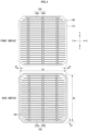
- FIG. 1 is a front view and a back view of a solar cell according to a first embodiment, which does not form part of the invention but is illustrated as a mere example suitable for understanding the invention.
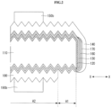
- FIG. 2 is a cross-sectional view of a solar cell shown in FIG. 1 cut along line II-II in the X-X direction.
- FIG. 3 is a front view and a back view showing a state in which a front collector electrode and a back collector electrode are removed from a solar cell shown in FIG. 1 .
- a solar cell according to the first embodiment includes a crystalline semiconductor substrate 110.
- a front passivation layer 120, a front doped layer 130, a front transparent conductive layer 140, and a front collector electrode 150 are sequentially stacked on the front surface (or a light incident surface) of the semiconductor substrate 110.
- a back passivation layer 160, a back doped layer 170, a back transparent conductive layer 180, and a back collector electrode 190 are sequentially stacked on the back surface of the semiconductor substrate 110.
- front surface refers to an upward facing surface in the accompanying drawings.
- back surface refers to a downward facing surface in the accompanying drawings.
- side surface refers to a surface facing both left and right sides in the accompanying drawings.
- front surface refers to a surface on which a transparent conductive layer having a relatively wide width is located among the transparent conductive layers 140 and 180. The surface on which the transparent conductive layer having a relatively wide width is located can be used as the front surface or the light incidence surface.
- the substrate 110 is a semiconductor substrate 110 made of crystalline silicon containing impurities of a first conductive type, for example, an n-type.
- the silicon may be single crystal silicon or polycrystalline silicon.
- the substrate 110 contains impurities of a Group V element such as phosphorus (P), arsenic (As), antimony (Sb), and the like.
- a Group V element such as phosphorus (P), arsenic (As), antimony (Sb), and the like.
- the substrate 110 may be a p-type and may be made of a semiconductor material other than silicon.
- the substrate 110 may contain impurities of a Group III element such as boron (B), gallium (Ga), indium (In), and the like.
- the substrate 110 has an n-type.
- the substrate 110 has a texturing surface whose surface is textured. More specifically, the substrate 110 includes a front surface on which the front passivation layer 120 is located and a back surface on which the back passivation layer 160 is located as texturing surfaces.
- the back surface of the semiconductor substrate 110 may be formed as a substantially flat surface without fine unevenness.
- the front passivation layer 120 located on the front surface of the semiconductor substrate 110 and the back passivation layer 160 located on the back surface of the semiconductor substrate 110 may be formed of substantially intrinsic i-type amorphous silicon (i-a-Si) or may be formed of a tunnel oxide.
- the front passivation layer 120 extends to the side surface of the substrate 110 and the back passivation layer 160 extends to the side surface of the substrate 110.
- the front passivation layer 120 and the back passivation layer 160 overlap each other on the side surface of the semiconductor substrate 110. Therefore, since the passivation effect at the side surface of the semiconductor substrate can be obtained, the passivation effect can be improved as compared with the instance where the side surface of the semiconductor substrate is not covered with the front and back passivation layers.
- overlap each other refers to a state in which at least a part of the front passivation layer and the back passivation layer overlaps each other on a projection surface when viewed from the side surface of the semiconductor substrate.
- the front doped layer 130 located on the front passivation layer 120 is an impurity portion having a second conductive type, for example, a p-type opposite the conductive type of the substrate 110.
- the front doped layer 130 is made of p-type amorphous silicon (p-a-Si) and forms a p-n junction and a hetero junction with the substrate 110.
- the back doped layer 170 located under the back passivation layer 160, that is, on the back surface of the semiconductor substrate 110 is an impurity portion having a first conductive type, for example, an n-type, which is the same as the conductive type of the substrate 110.
- the back doped layer 170 is made of n-type amorphous silicon and forms a hetero junction with the substrate 110.
- the front doped layer 130 located on the front surface (or the light incident surface) of the semiconductor substrate may be made of n-type amorphous silicon (n-a-Si).
- the back doped layer 170 located on the back surface (or the surface opposite to the light incident surface) of the semiconductor substrate may be made of p-type amorphous silicon (p-a-Si).
- the separated electrons move toward the back doped layer 170 and the separated holes move toward the front doped layer 130.
- the separated holes move toward the back doped layer 170, and the separated electrons move toward the front doped layer 130.
- the front passivation layer 120, the front doped layer 130, the back passivation layer 160, and the back doped layer 170 are sequentially stacked on the side surface of the semiconductor substrate 110 and overlap each other.
- the front doped layer may be formed only on the front surface of the semiconductor substrate
- the back doped layer may be formed only on the back surface of the semiconductor substrate. In this instance, only the front passivation layer and the back passivation layer overlap each other on the side surface of the semiconductor substrate.
- the back collector electrode 190 is composed of the plurality of second finger electrodes 190a and the second bus bar electrode 190b.
- the solar cell having the back collector electrode 190' as a sheet electrode since light cannot be incident on the back surface of the semiconductor substrate 110, the solar cell having the back collector electrode 190' as a sheet electrode can be used as a mono-facial solar cell.
- the solar cell module can be manufactured by electrically connecting a plurality of solar cells using wirings (for example, interconnectors or ribbons), disposing the plurality of solar cells between a pair of substrates, and performing a lamination process in a state where a sealing material is disposed between the pair of substrates.
- wirings for example, interconnectors or ribbons
- n-type single crystal silicon substrate is cleaned to remove impurities, and etching is performed using an etchant composed of an aqueous solution of sodium hydroxide.
- a semiconductor substrate 110 having texturing surfaces formed on front and back surfaces of the silicon substrate is prepared.
- a front passivation layer 120 made of i-type amorphous silicon and a front doped layer 130 made of p-type amorphous silicon are sequentially formed on the front surface and the side surface of the substrate 110, and a back passivation layer 160 made of i-type amorphous silicon and a back doped layer 170 made of n-type amorphous silicon are sequentially formed on the back surface and the side surface of the substrate 110.
- RF radio-frequency
- CVD chemical vapor deposition
- the front passivation layer 120, the front doped layer 130, the back passivation layer 160, and the back doped layer 170 overlap each other on the side surface of the semiconductor substrate 110.
- a front transparent conductive layer 140 is formed on the front doped layer 130 and a back transparent conductive layer 180 is formed on the back surface of the back doped layer 170.
- the sputtering device shown in FIG. 7 is a device capable of simultaneously forming transparent conductive layers 140 and 180 on both surfaces of the semiconductor substrate 110, that is, a front surface and a back surface.
- Each of the sputtering targets 200 is located above the front surface and below the back surface of the semiconductor substrate 110 placed on a tray 210.
- the front transparent conductive layer 140 and the back transparent conductive layer 180 can be simultaneously formed in the same sputtering process.
- the tray 210 holding the semiconductor substrate 110 has a contact portion 212 that is physically and directly in contact with the back surface of the semiconductor substrate 110.
- the contact portion 212 is formed as a shape that covers the edge region A1 of the back surface of the semiconductor substrate 110.
- the front transparent conductive layer 140 and the back transparent conductive layer 180 are formed using the sputtering device shown in FIG. 7 , the front transparent conductive layer 140 is formed entirely in the center region A2 and the edge region A1 of the front surface of the semiconductor substrate 110 and extends to the side surface of the semiconductor substrate 110.
- the back transparent conductive layer 180 is formed only in the central region A2 of the back surface of the semiconductor substrate 110.
- the front passivation layer 120, the front doped layer 130, the back passivation layer 160, and the back doped layer 170 overlap each other on the side surface of the semiconductor substrate 110.
- the RPD device shown in FIG. 8 is a device capable of sequentially forming transparent conductive layers 140 and 180 on both surfaces of the semiconductor substrate 110, that is, a front surface and a back surface by flipping the semiconductor substrate 110.
- the sputtering target 200 is located only below the back surface of the semiconductor substrate 110 placed on a tray 210 and 220.
- the back transparent conductive layer 180 and the front transparent conductive layer 140 can be sequentially formed.
- the tray 210 holding the semiconductor substrate 110 to form the back transparent conductive layer 180 has a contact portion 212 that is physically and directly in contact with the back surface of the semiconductor substrate 110.
- the contact portion 212 is formed of a shape that covers the edge region A1 of the back surface of the semiconductor substrate 110.
- the tray 220 holding the semiconductor substrate 110 to form the front transparent conductive layer 140 has a contact portion 222 that is physically and directly in contact with the front surface of the semiconductor substrate 110.
- the contact portion 222 is formed as a shape that covers the non-formed portion A3 in the edge region A1 of the first surface of the semiconductor substrate 110.
- the back transparent conductive layer 180 when the back transparent conductive layer 180 are formed using the RPD device shown in FIG. 8 , the back transparent conductive layer 180 may be formed only in the center region A2 of the back surface of the semiconductor substrate 110.
- the front transparent conductive layer 140 when the front transparent conductive layer 140 is formed in a state in which the semiconductor substrate 110 is placed on the tray 220 so that the front surface of the semiconductor substrate 110 is in contact with the contact portion 222 of the tray 220 by flipping the semiconductor substrate 110, the front transparent conductive layer 140 may be formed in the center region A2 of the front surface of the semiconductor substrate 110 and in the edge region A1 except for the non-formed portion A3.
- an annealing process for crystallizing the front transparent conductive layer 140 and the back transparent conductive layer 180 may be performed, and the front collector electrode 150 and the back collector electrode 190 may be formed using a screen printing method.
Landscapes
- Engineering & Computer Science (AREA)
- Chemical & Material Sciences (AREA)
- Materials Engineering (AREA)
- Manufacturing & Machinery (AREA)
- Physics & Mathematics (AREA)
- Mechanical Engineering (AREA)
- Optics & Photonics (AREA)
- Photovoltaic Devices (AREA)
- Life Sciences & Earth Sciences (AREA)
- Sustainable Development (AREA)
- Sustainable Energy (AREA)
Claims (7)
- Solarzelle, umfassend:ein kristallines Halbleitersubstrat (110) eines ersten Leitfähigkeitstyps;eine vordere Passivierungsschicht (120), die zwischen der vorderen dotierten Schicht und dem Halbleitersubstrat angeordnet ist,eine vordere dotierte Schicht (130), die auf einer Vorderseite des Halbleitersubstrats angeordnet ist und einen Heteroübergang mit dem Halbleitersubstrat bildet;eine hintere Passivierungsschicht (160), die zwischen der hinteren dotierten Schicht und dem Halbleitersubstrat angeordnet ist,eine hintere dotierte Schicht (170), die auf einer Rückseite des Halbleitersubstrats angeordnet ist und einen Heteroübergang mit dem Halbleitersubstrat bildet;eine vordere transparente leitfähige Schicht (140), die auf der vorderen dotierten Schicht angeordnet ist;eine hintere transparente leitfähige Schicht (180), die unter der hinteren dotierten Schicht angeordnet ist,eine vordere Sammelelektrode (150), die auf der vorderen transparenten leitfähigen Schicht angeordnet ist; undeine hintere Sammelelektrode (190, 190'), die unter der hinteren transparenten leitfähigen Schicht angeordnet ist,wobei die vordere Sammelelektrode (150) nicht physikalisch und direkt in Kontakt mit der vorderen dotierten Schicht (130) ist,wobei die hintere Sammelelektrode (190, 190') nicht physikalisch und direkt in Kontakt mit der hinteren dotierten Schicht (170) ist,wobei eine der vorderen dotierten Schicht und der hinteren dotierten Schicht einen dem ersten Leitfähigkeitstyp entgegengesetzten zweiten Leitfähigkeitstyp aufweist, um einen p-n-Übergang mit dem Halbleitersubstrat zu bilden, und die andere der vorderen dotierten Schicht und der hinteren dotierten Schicht den ersten Leitfähigkeitstyp aufweist, undwobei ein ebener Bereich der vorderen transparenten leitfähigen Schicht größer ist als ein ebener Bereich der hinteren transparenten leitfähigen Schicht,dadurch gekennzeichnet, dassdie vordere Passivierungsschicht (120) und die hintere Passivierungsschicht (160) auf der Seitenfläche des Halbleitersubstrats (110) einander überlappen und die vordere transparente leitfähige Schicht (140) ferner auf der vorderen Passivierungsschicht und der hinteren Passivierungsschicht angeordnet ist, die sich auf der Seitenfläche des Halbleitersubstrats einander überlappen, wobei die vordere Sammelelektrode (150) eine Mehrzahl erster Fingerelektroden (150a), die sich in einer ersten Richtung erstrecken, und mindestens eine erste Sammelschienenelektrode (150b) umfasst, die sich in einer zweiten Richtung erstreckt und physikalisch mit der Mehrzahl erster Fingerelektroden verbunden ist,wobei die hintere Sammelelektrode (190,1909 eine Mehrzahl zweiter Fingerelektroden (190a), die sich in der ersten Richtung erstrecken, und mindestens eine zweite Sammelschienenelektrode (190b) umfasst, die sich in der zweiten Richtung erstreckt und physikalisch mit der Mehrzahl zweiter Fingerelektroden verbunden ist, oder eine Plattenelektrode (190') umfasst, welche die Rückseite einer hinteren transparenten leitfähigen Schicht vollständig bedeckt,wobei jede der Vorderseite und der Rückseite des Halbleitersubstrats einen Randbereich (A1), der kontinuierlich von einem Rand des Halbleitersubstrats zu einem Inneren des Halbleitersubstrats entlang dem Rand ausgebildet ist, und einem mittleren Bereich (A2) umfasst, der mit Ausnahme des Randbereichs ein verbleibender Bereich ist,wobei die vordere transparente leitfähige Schicht (140) in dem mittleren Bereich und einem verbleibenden Randbereich mit Ausnahme eines nicht ausgebildeten Abschnitts (A3) ausgebildet ist, der diskontinuierlich in einem Teil des Randbereichs der Vorderseite ausgebildet ist,wobei der nicht ausgebildete Abschnitt (A3) an beiden Enden der mindestens einen ersten Sammelschienenelektrode (150b) angeordnet ist und eine Breite (W1) in der ersten Richtung der beiden Enden der erstenSammelschienenelektrode (150b) größer ist als eine Breite (W2) in der ersten Richtung eines verbleibenden Abschnitts der ersten Sammelschienenelektrode (150b), der zwischen den beiden Enden entlang der zweiten Richtung angeordnet ist, undwobei die hintere transparente leitfähige Schicht (180) mit Ausnahme des Randbereichs der Rückseite nur im mittleren Bereich ausgebildet ist.
- Solarzelle nach Anspruch 1, wobei eine Breite des Randbereichs (A1) der Rückseite des Halbleitersubstrats 0,5 mm bis 1,0 mm beträgt.
- Solarzelle nach Anspruch 1 oder 2, wobei das Halbleitersubstrat (110) einen Störstoff vom n-Typ enthält, die vordere dotierte Schicht aus amorphem Silicium vom p-Typ gebildet ist, das einen Störstoff vom p-Typ enthält, und die hintere dotierte Schicht aus amorphem Silicium vom n-Typ, das einen Störstoff vom n-Typ enthält, gebildet ist.
- Solarzelle nach einem der Ansprüche 1 bis 3, wobei jedes der beiden Enden der mindestens einen ersten Sammelschienenelektrode (150b) entlang der ersten Richtung in beide Seiten des nicht ausgebildeten Abschnitts unterteilt ist, wobei der nicht ausgebildete Abschnitt zwischen den unterteilten beiden Enden angeordnet ist, wobei die ersten Fingerelektroden (150a) auf der vorderen transparenten leitfähigen Schicht (140) des Randbereichs mit Ausnahme des nicht ausgebildeten Abschnitts angeordnet sind, und die beiden Enden der geteilten ersten Sammelschienenelektrode sich zu dem Randbereich erstrecken und physikalisch mit den ersten Fingerelektroden verbunden sind.
- Solarzelle nach einem der Ansprüche 1 bis 4, wobei eine Breite (W3) in der ersten Richtung des nicht ausgebildeten Abschnitts kleiner ist als die Breite in der ersten Richtung des verbleibenden Abschnitts der mindestens einen ersten Sammelschienenelektrode (150b), und eine Länge (L1) in der zweiten Richtung des nicht ausgebildeten Abschnitts kleiner ist als ein Abstand (D1) zwischen zwei ersten Fingerelektroden (150a), die in der zweiten Richtung nebeneinander befinden.
- Solarzelle nach einem der Ansprüche 1 bis 5, wobei die vordere Passivierungsschicht und die hintere Passivierungsschicht aus intrinsisch amorphem Silicium oder einem Tunneloxid gebildet sind.
- Solarzelle nach Anspruch 6, wobei die vordere dotierte Schicht (130) und die hintere dotierte Schicht (170) an beiden Seitenflächen des Halbleitersubstrats einander überlappen.
Priority Applications (1)
| Application Number | Priority Date | Filing Date | Title |
|---|---|---|---|
| EP19173752.7A EP3544059A1 (de) | 2016-01-20 | 2017-01-19 | Solarzelle |
Applications Claiming Priority (1)
| Application Number | Priority Date | Filing Date | Title |
|---|---|---|---|
| KR1020160006863A KR101778128B1 (ko) | 2016-01-20 | 2016-01-20 | 태양전지 |
Related Child Applications (2)
| Application Number | Title | Priority Date | Filing Date |
|---|---|---|---|
| EP19173752.7A Division-Into EP3544059A1 (de) | 2016-01-20 | 2017-01-19 | Solarzelle |
| EP19173752.7A Division EP3544059A1 (de) | 2016-01-20 | 2017-01-19 | Solarzelle |
Publications (3)
| Publication Number | Publication Date |
|---|---|
| EP3196945A1 EP3196945A1 (de) | 2017-07-26 |
| EP3196945B1 EP3196945B1 (de) | 2019-06-19 |
| EP3196945B2 true EP3196945B2 (de) | 2025-07-02 |
Family
ID=57850981
Family Applications (2)
| Application Number | Title | Priority Date | Filing Date |
|---|---|---|---|
| EP19173752.7A Withdrawn EP3544059A1 (de) | 2016-01-20 | 2017-01-19 | Solarzelle |
| EP17152171.9A Active EP3196945B2 (de) | 2016-01-20 | 2017-01-19 | Solarzelle |
Family Applications Before (1)
| Application Number | Title | Priority Date | Filing Date |
|---|---|---|---|
| EP19173752.7A Withdrawn EP3544059A1 (de) | 2016-01-20 | 2017-01-19 | Solarzelle |
Country Status (5)
| Country | Link |
|---|---|
| US (1) | US20170207351A1 (de) |
| EP (2) | EP3544059A1 (de) |
| JP (1) | JP6408616B2 (de) |
| KR (1) | KR101778128B1 (de) |
| CN (1) | CN106997906B (de) |
Families Citing this family (20)
| Publication number | Priority date | Publication date | Assignee | Title |
|---|---|---|---|---|
| KR102541127B1 (ko) * | 2017-09-05 | 2023-06-09 | 상라오 징코 솔라 테크놀러지 디벨롭먼트 컴퍼니, 리미티드 | 텐덤 태양전지 및 그 제조 방법 |
| USD839180S1 (en) * | 2017-10-31 | 2019-01-29 | Flex Ltd. | Busbar-less solar cell |
| KR20200104211A (ko) * | 2018-01-18 | 2020-09-03 | 플렉스 엘티디 | 슁글드 태양광 모듈을 제조하는 방법 |
| WO2020145568A1 (ko) * | 2019-01-09 | 2020-07-16 | 엘지전자 주식회사 | 태양전지 제조 방법 |
| CN113330584B (zh) * | 2019-01-24 | 2024-04-23 | 株式会社钟化 | 太阳能电池制造用基板托盘及太阳能电池的制造方法 |
| DE102019123785A1 (de) | 2019-09-05 | 2021-03-11 | Meyer Burger (Germany) Gmbh | Rückseitenemitter-Solarzellenstruktur mit einem Heteroübergang sowie Verfahren und Vorrichtung zur Herstellung derselben |
| DE102019123758A1 (de) | 2019-09-05 | 2021-03-11 | Schaeffler Technologies AG & Co. KG | Wellgetriebe zur variablen Ventilsteuerung einer Brennkraftmaschine |
| CN114975683B (zh) * | 2020-09-30 | 2023-06-06 | 浙江晶科能源有限公司 | 一种太阳能电池及其制备方法 |
| FR3131083B1 (fr) | 2021-12-16 | 2024-09-20 | Commissariat Energie Atomique | Cellule photovoltaïque a contacts passives et a revêtement antireflet |
| CN116130530B (zh) * | 2022-09-07 | 2024-07-05 | 隆基绿能科技股份有限公司 | Topcon太阳能电池及其制备方法 |
| CN117673176A (zh) | 2022-09-08 | 2024-03-08 | 浙江晶科能源有限公司 | 太阳能电池及光伏组件 |
| CN117238987A (zh) | 2022-09-08 | 2023-12-15 | 浙江晶科能源有限公司 | 太阳能电池及光伏组件 |
| CN117712199A (zh) | 2022-09-08 | 2024-03-15 | 浙江晶科能源有限公司 | 太阳能电池及光伏组件 |
| CN115799350B (zh) * | 2022-11-11 | 2024-09-27 | 通威太阳能(金堂)有限公司 | 太阳电池及其制备方法 |
| KR102638070B1 (ko) * | 2023-02-16 | 2024-02-20 | 한국화학연구원 | 반사방지 및 도핑효과가 있는 광학박막의 제조방법 및 이에 의해 제조된 광학박막 |
| CN222088615U (zh) * | 2024-04-17 | 2024-11-29 | 浙江爱旭太阳能科技有限公司 | 太阳能电池片、电池组件和光伏系统 |
| CN117423754B (zh) * | 2023-12-19 | 2024-04-23 | 天合光能股份有限公司 | 异质结电池及其制作方法、光伏组件及光伏系统 |
| CN223040504U (zh) * | 2024-08-13 | 2025-06-27 | 天合光能股份有限公司 | 太阳能电池 |
| WO2026050345A1 (en) * | 2024-08-29 | 2026-03-05 | Corning Incorporated | Heterojunction photovoltaic cell and method of making the same |
| CN119677225B (zh) * | 2024-11-29 | 2025-09-02 | 隆基绿能科技股份有限公司 | 一种背接触电池和光伏组件 |
Family Cites Families (18)
| Publication number | Priority date | Publication date | Assignee | Title |
|---|---|---|---|---|
| US4831565A (en) | 1986-10-03 | 1989-05-16 | Canadian Corporate Management Company Limited | Process control equipment for adverse environments |
| JP3349308B2 (ja) * | 1995-10-26 | 2002-11-25 | 三洋電機株式会社 | 光起電力素子 |
| JP3825585B2 (ja) * | 1999-07-26 | 2006-09-27 | 三洋電機株式会社 | 光起電力素子の製造方法 |
| JP4194379B2 (ja) * | 2003-01-22 | 2008-12-10 | 三洋電機株式会社 | 光起電力装置 |
| JP4222991B2 (ja) * | 2004-01-13 | 2009-02-12 | 三洋電機株式会社 | 光起電力装置 |
| JP4502845B2 (ja) * | 2005-02-25 | 2010-07-14 | 三洋電機株式会社 | 光起電力素子 |
| HUE046791T2 (hu) * | 2005-02-25 | 2020-03-30 | Panasonic Ip Man Co Ltd | Fotovoltaikus cella |
| JP4040659B2 (ja) * | 2006-04-14 | 2008-01-30 | シャープ株式会社 | 太陽電池、太陽電池ストリング、および太陽電池モジュール |
| JP2009088203A (ja) * | 2007-09-28 | 2009-04-23 | Sanyo Electric Co Ltd | 太陽電池、太陽電池モジュール及び太陽電池の製造方法 |
| JP5147672B2 (ja) * | 2008-01-31 | 2013-02-20 | 三洋電機株式会社 | 太陽電池モジュール及び太陽電池モジュールの製造方法 |
| KR101699300B1 (ko) * | 2010-09-27 | 2017-01-24 | 엘지전자 주식회사 | 태양전지 및 이의 제조 방법 |
| JP5496856B2 (ja) * | 2010-11-02 | 2014-05-21 | 三洋電機株式会社 | 光起電力素子の製造方法 |
| EP2450970A1 (de) | 2010-11-05 | 2012-05-09 | Roth & Rau AG | Kantenisolierung mittels Abziehen |
| EP2657978A4 (de) * | 2011-01-31 | 2014-03-19 | Sanyo Electric Co | Photoelektrischer wandler und verfahren zu seiner herstellung |
| KR20120104846A (ko) * | 2011-03-14 | 2012-09-24 | 주성엔지니어링(주) | 태양전지 및 그 제조방법 |
| DE102011006833A1 (de) | 2011-04-06 | 2012-10-11 | Roth & Rau Ag | Substratträger |
| EP4404282A3 (de) | 2012-07-02 | 2024-10-23 | Meyer Burger (Germany) GmbH | Heteroübergangssolarzelle mit kantenisolierung |
| CN104584237B (zh) * | 2012-08-29 | 2017-03-08 | 三菱电机株式会社 | 光生伏打元件及其制造方法 |
-
2016
- 2016-01-20 KR KR1020160006863A patent/KR101778128B1/ko active Active
-
2017
- 2017-01-13 CN CN201710024078.0A patent/CN106997906B/zh active Active
- 2017-01-18 US US15/408,903 patent/US20170207351A1/en not_active Abandoned
- 2017-01-19 EP EP19173752.7A patent/EP3544059A1/de not_active Withdrawn
- 2017-01-19 EP EP17152171.9A patent/EP3196945B2/de active Active
- 2017-01-19 JP JP2017007492A patent/JP6408616B2/ja not_active Expired - Fee Related
Also Published As
| Publication number | Publication date |
|---|---|
| CN106997906A (zh) | 2017-08-01 |
| EP3196945B1 (de) | 2019-06-19 |
| JP2017130664A (ja) | 2017-07-27 |
| CN106997906B (zh) | 2019-08-06 |
| KR20170087179A (ko) | 2017-07-28 |
| EP3196945A1 (de) | 2017-07-26 |
| KR101778128B1 (ko) | 2017-09-13 |
| EP3544059A1 (de) | 2019-09-25 |
| JP6408616B2 (ja) | 2018-10-17 |
| US20170207351A1 (en) | 2017-07-20 |
Similar Documents
| Publication | Publication Date | Title |
|---|---|---|
| EP3196945B2 (de) | Solarzelle | |
| EP3193375B1 (de) | Solarzelle | |
| US11056598B2 (en) | Solar cell | |
| US9379270B2 (en) | Bifacial crystalline silicon solar panel with reflector | |
| EP2434548B1 (de) | Solarzelle und Verfahren zu ihrer Herstellung | |
| KR101918738B1 (ko) | 태양 전지 | |
| EP2757591B1 (de) | Solarzellenmodul | |
| EP2522031B1 (de) | Sonnenkollektormodul und verfahren zur herstellung eines solchen sonnenkollektormoduls | |
| EP2341548B1 (de) | Solarzellenmodul | |
| US9508875B2 (en) | Solar cell and method for manufacturing the same | |
| US20160197204A1 (en) | Solar cell and method for manufacturing the same | |
| US20190088802A1 (en) | Moisture-resistant solar cells for solar roof tiles | |
| US8329500B2 (en) | Method of manufacturing photovoltaic device | |
| KR20140095658A (ko) | 태양 전지 | |
| KR20150090607A (ko) | 태양 전지 및 이의 제조 방법 | |
| KR20190034968A (ko) | 태양 전지 및 이를 포함하는 태양 전지 패널 | |
| CN120857647B (zh) | 光伏组件及其制造方法 | |
| WO2025119870A1 (en) | An electrode assembly and a method of manufacturing an electrode assembly |
Legal Events
| Date | Code | Title | Description |
|---|---|---|---|
| PUAI | Public reference made under article 153(3) epc to a published international application that has entered the european phase |
Free format text: ORIGINAL CODE: 0009012 |
|
| STAA | Information on the status of an ep patent application or granted ep patent |
Free format text: STATUS: THE APPLICATION HAS BEEN PUBLISHED |
|
| AK | Designated contracting states |
Kind code of ref document: A1 Designated state(s): AL AT BE BG CH CY CZ DE DK EE ES FI FR GB GR HR HU IE IS IT LI LT LU LV MC MK MT NL NO PL PT RO RS SE SI SK SM TR |
|
| AX | Request for extension of the european patent |
Extension state: BA ME |
|
| STAA | Information on the status of an ep patent application or granted ep patent |
Free format text: STATUS: REQUEST FOR EXAMINATION WAS MADE |
|
| 17P | Request for examination filed |
Effective date: 20171023 |
|
| RBV | Designated contracting states (corrected) |
Designated state(s): AL AT BE BG CH CY CZ DE DK EE ES FI FR GB GR HR HU IE IS IT LI LT LU LV MC MK MT NL NO PL PT RO RS SE SI SK SM TR |
|
| GRAP | Despatch of communication of intention to grant a patent |
Free format text: ORIGINAL CODE: EPIDOSNIGR1 |
|
| STAA | Information on the status of an ep patent application or granted ep patent |
Free format text: STATUS: GRANT OF PATENT IS INTENDED |
|
| RIC1 | Information provided on ipc code assigned before grant |
Ipc: H01L 31/0224 20060101AFI20181212BHEP Ipc: H01L 31/0747 20120101ALI20181212BHEP |
|
| INTG | Intention to grant announced |
Effective date: 20190114 |
|
| RAP1 | Party data changed (applicant data changed or rights of an application transferred) |
Owner name: LG ELECTRONICS INC. |
|
| RIN1 | Information on inventor provided before grant (corrected) |
Inventor name: JI, KWANGSUN Inventor name: HWANG, SUNGHYUN Inventor name: LEE, HONGCHEOL Inventor name: LEE, SEUNGYOON |
|
| GRAS | Grant fee paid |
Free format text: ORIGINAL CODE: EPIDOSNIGR3 |
|
| GRAA | (expected) grant |
Free format text: ORIGINAL CODE: 0009210 |
|
| STAA | Information on the status of an ep patent application or granted ep patent |
Free format text: STATUS: THE PATENT HAS BEEN GRANTED |
|
| AK | Designated contracting states |
Kind code of ref document: B1 Designated state(s): AL AT BE BG CH CY CZ DE DK EE ES FI FR GB GR HR HU IE IS IT LI LT LU LV MC MK MT NL NO PL PT RO RS SE SI SK SM TR |
|
| REG | Reference to a national code |
Ref country code: GB Ref legal event code: FG4D |
|
| REG | Reference to a national code |
Ref country code: CH Ref legal event code: EP |
|
| REG | Reference to a national code |
Ref country code: IE Ref legal event code: FG4D |
|
| REG | Reference to a national code |
Ref country code: DE Ref legal event code: R096 Ref document number: 602017004528 Country of ref document: DE |
|
| REG | Reference to a national code |
Ref country code: AT Ref legal event code: REF Ref document number: 1146600 Country of ref document: AT Kind code of ref document: T Effective date: 20190715 |
|
| REG | Reference to a national code |
Ref country code: NL Ref legal event code: MP Effective date: 20190619 |
|
| PG25 | Lapsed in a contracting state [announced via postgrant information from national office to epo] |
Ref country code: FI Free format text: LAPSE BECAUSE OF FAILURE TO SUBMIT A TRANSLATION OF THE DESCRIPTION OR TO PAY THE FEE WITHIN THE PRESCRIBED TIME-LIMIT Effective date: 20190619 Ref country code: NO Free format text: LAPSE BECAUSE OF FAILURE TO SUBMIT A TRANSLATION OF THE DESCRIPTION OR TO PAY THE FEE WITHIN THE PRESCRIBED TIME-LIMIT Effective date: 20190919 Ref country code: LT Free format text: LAPSE BECAUSE OF FAILURE TO SUBMIT A TRANSLATION OF THE DESCRIPTION OR TO PAY THE FEE WITHIN THE PRESCRIBED TIME-LIMIT Effective date: 20190619 Ref country code: HR Free format text: LAPSE BECAUSE OF FAILURE TO SUBMIT A TRANSLATION OF THE DESCRIPTION OR TO PAY THE FEE WITHIN THE PRESCRIBED TIME-LIMIT Effective date: 20190619 Ref country code: SE Free format text: LAPSE BECAUSE OF FAILURE TO SUBMIT A TRANSLATION OF THE DESCRIPTION OR TO PAY THE FEE WITHIN THE PRESCRIBED TIME-LIMIT Effective date: 20190619 Ref country code: AL Free format text: LAPSE BECAUSE OF FAILURE TO SUBMIT A TRANSLATION OF THE DESCRIPTION OR TO PAY THE FEE WITHIN THE PRESCRIBED TIME-LIMIT Effective date: 20190619 |
|
| REG | Reference to a national code |
Ref country code: LT Ref legal event code: MG4D |
|
| PG25 | Lapsed in a contracting state [announced via postgrant information from national office to epo] |
Ref country code: GR Free format text: LAPSE BECAUSE OF FAILURE TO SUBMIT A TRANSLATION OF THE DESCRIPTION OR TO PAY THE FEE WITHIN THE PRESCRIBED TIME-LIMIT Effective date: 20190920 Ref country code: LV Free format text: LAPSE BECAUSE OF FAILURE TO SUBMIT A TRANSLATION OF THE DESCRIPTION OR TO PAY THE FEE WITHIN THE PRESCRIBED TIME-LIMIT Effective date: 20190619 Ref country code: BG Free format text: LAPSE BECAUSE OF FAILURE TO SUBMIT A TRANSLATION OF THE DESCRIPTION OR TO PAY THE FEE WITHIN THE PRESCRIBED TIME-LIMIT Effective date: 20190919 Ref country code: RS Free format text: LAPSE BECAUSE OF FAILURE TO SUBMIT A TRANSLATION OF THE DESCRIPTION OR TO PAY THE FEE WITHIN THE PRESCRIBED TIME-LIMIT Effective date: 20190619 |
|
| REG | Reference to a national code |
Ref country code: AT Ref legal event code: MK05 Ref document number: 1146600 Country of ref document: AT Kind code of ref document: T Effective date: 20190619 |
|
| PG25 | Lapsed in a contracting state [announced via postgrant information from national office to epo] |
Ref country code: EE Free format text: LAPSE BECAUSE OF FAILURE TO SUBMIT A TRANSLATION OF THE DESCRIPTION OR TO PAY THE FEE WITHIN THE PRESCRIBED TIME-LIMIT Effective date: 20190619 Ref country code: PT Free format text: LAPSE BECAUSE OF FAILURE TO SUBMIT A TRANSLATION OF THE DESCRIPTION OR TO PAY THE FEE WITHIN THE PRESCRIBED TIME-LIMIT Effective date: 20191021 Ref country code: CZ Free format text: LAPSE BECAUSE OF FAILURE TO SUBMIT A TRANSLATION OF THE DESCRIPTION OR TO PAY THE FEE WITHIN THE PRESCRIBED TIME-LIMIT Effective date: 20190619 Ref country code: RO Free format text: LAPSE BECAUSE OF FAILURE TO SUBMIT A TRANSLATION OF THE DESCRIPTION OR TO PAY THE FEE WITHIN THE PRESCRIBED TIME-LIMIT Effective date: 20190619 Ref country code: SK Free format text: LAPSE BECAUSE OF FAILURE TO SUBMIT A TRANSLATION OF THE DESCRIPTION OR TO PAY THE FEE WITHIN THE PRESCRIBED TIME-LIMIT Effective date: 20190619 Ref country code: NL Free format text: LAPSE BECAUSE OF FAILURE TO SUBMIT A TRANSLATION OF THE DESCRIPTION OR TO PAY THE FEE WITHIN THE PRESCRIBED TIME-LIMIT Effective date: 20190619 Ref country code: AT Free format text: LAPSE BECAUSE OF FAILURE TO SUBMIT A TRANSLATION OF THE DESCRIPTION OR TO PAY THE FEE WITHIN THE PRESCRIBED TIME-LIMIT Effective date: 20190619 |
|
| PG25 | Lapsed in a contracting state [announced via postgrant information from national office to epo] |
Ref country code: IT Free format text: LAPSE BECAUSE OF FAILURE TO SUBMIT A TRANSLATION OF THE DESCRIPTION OR TO PAY THE FEE WITHIN THE PRESCRIBED TIME-LIMIT Effective date: 20190619 Ref country code: IS Free format text: LAPSE BECAUSE OF FAILURE TO SUBMIT A TRANSLATION OF THE DESCRIPTION OR TO PAY THE FEE WITHIN THE PRESCRIBED TIME-LIMIT Effective date: 20191019 Ref country code: SM Free format text: LAPSE BECAUSE OF FAILURE TO SUBMIT A TRANSLATION OF THE DESCRIPTION OR TO PAY THE FEE WITHIN THE PRESCRIBED TIME-LIMIT Effective date: 20190619 Ref country code: ES Free format text: LAPSE BECAUSE OF FAILURE TO SUBMIT A TRANSLATION OF THE DESCRIPTION OR TO PAY THE FEE WITHIN THE PRESCRIBED TIME-LIMIT Effective date: 20190619 |
|
| REG | Reference to a national code |
Ref country code: DE Ref legal event code: R026 Ref document number: 602017004528 Country of ref document: DE |
|
| PLBI | Opposition filed |
Free format text: ORIGINAL CODE: 0009260 |
|
| PG25 | Lapsed in a contracting state [announced via postgrant information from national office to epo] |
Ref country code: TR Free format text: LAPSE BECAUSE OF FAILURE TO SUBMIT A TRANSLATION OF THE DESCRIPTION OR TO PAY THE FEE WITHIN THE PRESCRIBED TIME-LIMIT Effective date: 20190619 |
|
| 26 | Opposition filed |
Opponent name: MEYER BURGER (GERMANY) GMBH Effective date: 20200304 |
|
| PLBI | Opposition filed |
Free format text: ORIGINAL CODE: 0009260 |
|
| PG25 | Lapsed in a contracting state [announced via postgrant information from national office to epo] |
Ref country code: DK Free format text: LAPSE BECAUSE OF FAILURE TO SUBMIT A TRANSLATION OF THE DESCRIPTION OR TO PAY THE FEE WITHIN THE PRESCRIBED TIME-LIMIT Effective date: 20190619 Ref country code: PL Free format text: LAPSE BECAUSE OF FAILURE TO SUBMIT A TRANSLATION OF THE DESCRIPTION OR TO PAY THE FEE WITHIN THE PRESCRIBED TIME-LIMIT Effective date: 20190619 |
|
| 26 | Opposition filed |
Opponent name: STRAWMAN LIMITED Effective date: 20200416 |
|
| PG25 | Lapsed in a contracting state [announced via postgrant information from national office to epo] |
Ref country code: IS Free format text: LAPSE BECAUSE OF FAILURE TO SUBMIT A TRANSLATION OF THE DESCRIPTION OR TO PAY THE FEE WITHIN THE PRESCRIBED TIME-LIMIT Effective date: 20200224 |
|
| PLAX | Notice of opposition and request to file observation + time limit sent |
Free format text: ORIGINAL CODE: EPIDOSNOBS2 |
|
| PG2D | Information on lapse in contracting state deleted |
Ref country code: IS |
|
| PG25 | Lapsed in a contracting state [announced via postgrant information from national office to epo] |
Ref country code: SI Free format text: LAPSE BECAUSE OF FAILURE TO SUBMIT A TRANSLATION OF THE DESCRIPTION OR TO PAY THE FEE WITHIN THE PRESCRIBED TIME-LIMIT Effective date: 20190619 Ref country code: MC Free format text: LAPSE BECAUSE OF FAILURE TO SUBMIT A TRANSLATION OF THE DESCRIPTION OR TO PAY THE FEE WITHIN THE PRESCRIBED TIME-LIMIT Effective date: 20190619 |
|
| REG | Reference to a national code |
Ref country code: CH Ref legal event code: PL |
|
| REG | Reference to a national code |
Ref country code: BE Ref legal event code: MM Effective date: 20200131 |
|
| PLBB | Reply of patent proprietor to notice(s) of opposition received |
Free format text: ORIGINAL CODE: EPIDOSNOBS3 |
|
| PG25 | Lapsed in a contracting state [announced via postgrant information from national office to epo] |
Ref country code: FR Free format text: LAPSE BECAUSE OF NON-PAYMENT OF DUE FEES Effective date: 20200131 Ref country code: LU Free format text: LAPSE BECAUSE OF NON-PAYMENT OF DUE FEES Effective date: 20200119 |
|
| PG25 | Lapsed in a contracting state [announced via postgrant information from national office to epo] |
Ref country code: BE Free format text: LAPSE BECAUSE OF NON-PAYMENT OF DUE FEES Effective date: 20200131 Ref country code: CH Free format text: LAPSE BECAUSE OF NON-PAYMENT OF DUE FEES Effective date: 20200131 Ref country code: LI Free format text: LAPSE BECAUSE OF NON-PAYMENT OF DUE FEES Effective date: 20200131 |
|
| PG25 | Lapsed in a contracting state [announced via postgrant information from national office to epo] |
Ref country code: IE Free format text: LAPSE BECAUSE OF NON-PAYMENT OF DUE FEES Effective date: 20200119 |
|
| GBPC | Gb: european patent ceased through non-payment of renewal fee |
Effective date: 20210119 |
|
| PG25 | Lapsed in a contracting state [announced via postgrant information from national office to epo] |
Ref country code: GB Free format text: LAPSE BECAUSE OF NON-PAYMENT OF DUE FEES Effective date: 20210119 |
|
| PG25 | Lapsed in a contracting state [announced via postgrant information from national office to epo] |
Ref country code: MT Free format text: LAPSE BECAUSE OF FAILURE TO SUBMIT A TRANSLATION OF THE DESCRIPTION OR TO PAY THE FEE WITHIN THE PRESCRIBED TIME-LIMIT Effective date: 20190619 Ref country code: CY Free format text: LAPSE BECAUSE OF FAILURE TO SUBMIT A TRANSLATION OF THE DESCRIPTION OR TO PAY THE FEE WITHIN THE PRESCRIBED TIME-LIMIT Effective date: 20190619 |
|
| APBM | Appeal reference recorded |
Free format text: ORIGINAL CODE: EPIDOSNREFNO |
|
| APBP | Date of receipt of notice of appeal recorded |
Free format text: ORIGINAL CODE: EPIDOSNNOA2O |
|
| APAH | Appeal reference modified |
Free format text: ORIGINAL CODE: EPIDOSCREFNO |
|
| APBM | Appeal reference recorded |
Free format text: ORIGINAL CODE: EPIDOSNREFNO |
|
| APBP | Date of receipt of notice of appeal recorded |
Free format text: ORIGINAL CODE: EPIDOSNNOA2O |
|
| PG25 | Lapsed in a contracting state [announced via postgrant information from national office to epo] |
Ref country code: MK Free format text: LAPSE BECAUSE OF FAILURE TO SUBMIT A TRANSLATION OF THE DESCRIPTION OR TO PAY THE FEE WITHIN THE PRESCRIBED TIME-LIMIT Effective date: 20190619 |
|
| APBQ | Date of receipt of statement of grounds of appeal recorded |
Free format text: ORIGINAL CODE: EPIDOSNNOA3O |
|
| APBQ | Date of receipt of statement of grounds of appeal recorded |
Free format text: ORIGINAL CODE: EPIDOSNNOA3O |
|
| RAP2 | Party data changed (patent owner data changed or rights of a patent transferred) |
Owner name: SHANGRAO JINKO SOLAR TECHNOLOGY DEVELOPMENT CO., LTD |
|
| REG | Reference to a national code |
Ref country code: DE Ref legal event code: R081 Ref document number: 602017004528 Country of ref document: DE Owner name: SHANGRAO JINKO SOLAR TECHNOLOGY DEVELOPMENT CO, CN Free format text: FORMER OWNER: LG ELECTRONICS INC., SEOUL, KR Ref country code: DE Ref legal event code: R082 Ref document number: 602017004528 Country of ref document: DE Representative=s name: DREISS PATENTANWAELTE PARTG MBB, DE Ref country code: DE Ref legal event code: R081 Ref document number: 602017004528 Country of ref document: DE Owner name: SHANGRAO XINYUAN YUEDONG TECHNOLOGY DEVELOPMEN, CN Free format text: FORMER OWNER: LG ELECTRONICS INC., SEOUL, KR |
|
| REG | Reference to a national code |
Ref country code: DE Ref legal event code: R081 Ref document number: 602017004528 Country of ref document: DE Owner name: SHANGRAO XINYUAN YUEDONG TECHNOLOGY DEVELOPMEN, CN Free format text: FORMER OWNER: SHANGRAO JINKO SOLAR TECHNOLOGY DEVELOPMENT CO., LTD, SHANGRAO, JIANGXI PROVINCE, CN |
|
| RAP4 | Party data changed (patent owner data changed or rights of a patent transferred) |
Owner name: SHANGRAO XINYUAN YUEDONG TECHNOLOGY DEVELOPMENT CO. LTD |
|
| REG | Reference to a national code |
Ref country code: DE Ref legal event code: R079 Ref document number: 602017004528 Country of ref document: DE Free format text: PREVIOUS MAIN CLASS: H01L0031022400 Ipc: H10F0077200000 |
|
| APBU | Appeal procedure closed |
Free format text: ORIGINAL CODE: EPIDOSNNOA9O |
|
| PGFP | Annual fee paid to national office [announced via postgrant information from national office to epo] |
Ref country code: DE Payment date: 20250121 Year of fee payment: 9 |
|
| PUAH | Patent maintained in amended form |
Free format text: ORIGINAL CODE: 0009272 |
|
| STAA | Information on the status of an ep patent application or granted ep patent |
Free format text: STATUS: PATENT MAINTAINED AS AMENDED |
|
| REG | Reference to a national code |
Ref country code: CH Ref legal event code: PK Free format text: BERICHTIGUNGEN |
|
| RIC2 | Information provided on ipc code assigned after grant |
Ipc: H10F 10/166 20250101ALI20250512BHEP Ipc: H10F 77/20 20250101AFI20250512BHEP |
|
| 27A | Patent maintained in amended form |
Effective date: 20250702 |
|
| AK | Designated contracting states |
Kind code of ref document: B2 Designated state(s): AL AT BE BG CH CY CZ DE DK EE ES FI FR GB GR HR HU IE IS IT LI LT LU LV MC MK MT NL NO PL PT RO RS SE SI SK SM TR |
|
| REG | Reference to a national code |
Ref country code: DE Ref legal event code: R102 Ref document number: 602017004528 Country of ref document: DE |
|
| PG25 | Lapsed in a contracting state [announced via postgrant information from national office to epo] |
Ref country code: IS Free format text: LAPSE BECAUSE OF NON-PAYMENT OF DUE FEES Effective date: 20200224 |