EP3192608B1 - Mehrfach segementierter intravaskular-führungsdraht mit einem schweissen; verfahren zur bekämpfung von rückpralleffekten beim festkörperwiderstandsschweissen von unterschiedlichen materialien - Google Patents
Mehrfach segementierter intravaskular-führungsdraht mit einem schweissen; verfahren zur bekämpfung von rückpralleffekten beim festkörperwiderstandsschweissen von unterschiedlichen materialien Download PDFInfo
- Publication number
- EP3192608B1 EP3192608B1 EP17159014.4A EP17159014A EP3192608B1 EP 3192608 B1 EP3192608 B1 EP 3192608B1 EP 17159014 A EP17159014 A EP 17159014A EP 3192608 B1 EP3192608 B1 EP 3192608B1
- Authority
- EP
- European Patent Office
- Prior art keywords
- force
- guide wire
- members
- weld
- follow
- Prior art date
- Legal status (The legal status is an assumption and is not a legal conclusion. Google has not performed a legal analysis and makes no representation as to the accuracy of the status listed.)
- Active
Links
- 238000000034 method Methods 0.000 title claims description 57
- 238000003466 welding Methods 0.000 title claims description 34
- 239000000463 material Substances 0.000 title description 27
- 239000007787 solid Substances 0.000 title description 15
- 229910001000 nickel titanium Inorganic materials 0.000 claims description 18
- 238000005304 joining Methods 0.000 claims description 16
- 229910001220 stainless steel Inorganic materials 0.000 claims description 15
- 239000010935 stainless steel Substances 0.000 claims description 14
- 239000007769 metal material Substances 0.000 claims description 12
- 230000008569 process Effects 0.000 claims description 9
- WAIPAZQMEIHHTJ-UHFFFAOYSA-N [Cr].[Co] Chemical class [Cr].[Co] WAIPAZQMEIHHTJ-UHFFFAOYSA-N 0.000 claims 2
- 229910052751 metal Inorganic materials 0.000 description 12
- 239000002184 metal Substances 0.000 description 12
- HLXZNVUGXRDIFK-UHFFFAOYSA-N nickel titanium Chemical compound [Ti].[Ti].[Ti].[Ti].[Ti].[Ti].[Ti].[Ti].[Ti].[Ti].[Ti].[Ni].[Ni].[Ni].[Ni].[Ni].[Ni].[Ni].[Ni].[Ni].[Ni].[Ni].[Ni].[Ni].[Ni] HLXZNVUGXRDIFK-UHFFFAOYSA-N 0.000 description 12
- PXHVJJICTQNCMI-UHFFFAOYSA-N Nickel Chemical compound [Ni] PXHVJJICTQNCMI-UHFFFAOYSA-N 0.000 description 10
- 238000006073 displacement reaction Methods 0.000 description 10
- 238000002844 melting Methods 0.000 description 10
- 230000008018 melting Effects 0.000 description 10
- 238000012360 testing method Methods 0.000 description 8
- 150000002739 metals Chemical class 0.000 description 7
- XEEYBQQBJWHFJM-UHFFFAOYSA-N Iron Chemical compound [Fe] XEEYBQQBJWHFJM-UHFFFAOYSA-N 0.000 description 6
- 238000004519 manufacturing process Methods 0.000 description 6
- 230000007704 transition Effects 0.000 description 6
- 238000000227 grinding Methods 0.000 description 5
- 238000005259 measurement Methods 0.000 description 5
- 229910052759 nickel Inorganic materials 0.000 description 5
- KDLHZDBZIXYQEI-UHFFFAOYSA-N Palladium Chemical compound [Pd] KDLHZDBZIXYQEI-UHFFFAOYSA-N 0.000 description 4
- 239000000853 adhesive Substances 0.000 description 4
- 230000001070 adhesive effect Effects 0.000 description 4
- 230000015572 biosynthetic process Effects 0.000 description 4
- 210000001503 joint Anatomy 0.000 description 4
- BASFCYQUMIYNBI-UHFFFAOYSA-N platinum Chemical compound [Pt] BASFCYQUMIYNBI-UHFFFAOYSA-N 0.000 description 4
- 238000002360 preparation method Methods 0.000 description 4
- RTAQQCXQSZGOHL-UHFFFAOYSA-N Titanium Chemical compound [Ti] RTAQQCXQSZGOHL-UHFFFAOYSA-N 0.000 description 3
- 210000004204 blood vessel Anatomy 0.000 description 3
- 230000000052 comparative effect Effects 0.000 description 3
- 238000010438 heat treatment Methods 0.000 description 3
- 229910052742 iron Inorganic materials 0.000 description 3
- 238000003908 quality control method Methods 0.000 description 3
- 238000007493 shaping process Methods 0.000 description 3
- 229910000679 solder Inorganic materials 0.000 description 3
- 239000010936 titanium Substances 0.000 description 3
- 229910052719 titanium Inorganic materials 0.000 description 3
- RYGMFSIKBFXOCR-UHFFFAOYSA-N Copper Chemical compound [Cu] RYGMFSIKBFXOCR-UHFFFAOYSA-N 0.000 description 2
- 238000005275 alloying Methods 0.000 description 2
- 229910001566 austenite Inorganic materials 0.000 description 2
- 238000005452 bending Methods 0.000 description 2
- 230000009286 beneficial effect Effects 0.000 description 2
- 230000036760 body temperature Effects 0.000 description 2
- 229910017052 cobalt Inorganic materials 0.000 description 2
- 239000010941 cobalt Substances 0.000 description 2
- GUTLYIVDDKVIGB-UHFFFAOYSA-N cobalt atom Chemical compound [Co] GUTLYIVDDKVIGB-UHFFFAOYSA-N 0.000 description 2
- 229910052802 copper Inorganic materials 0.000 description 2
- 239000010949 copper Substances 0.000 description 2
- 230000008878 coupling Effects 0.000 description 2
- 238000010168 coupling process Methods 0.000 description 2
- 238000005859 coupling reaction Methods 0.000 description 2
- 230000001066 destructive effect Effects 0.000 description 2
- 230000001747 exhibiting effect Effects 0.000 description 2
- 238000009499 grossing Methods 0.000 description 2
- 238000007542 hardness measurement Methods 0.000 description 2
- 229910000734 martensite Inorganic materials 0.000 description 2
- 229910052763 palladium Inorganic materials 0.000 description 2
- 230000036961 partial effect Effects 0.000 description 2
- 229910052697 platinum Inorganic materials 0.000 description 2
- 230000002829 reductive effect Effects 0.000 description 2
- 238000009864 tensile test Methods 0.000 description 2
- 229910052720 vanadium Inorganic materials 0.000 description 2
- GPPXJZIENCGNKB-UHFFFAOYSA-N vanadium Chemical compound [V]#[V] GPPXJZIENCGNKB-UHFFFAOYSA-N 0.000 description 2
- 210000005166 vasculature Anatomy 0.000 description 2
- 241000600039 Chromis punctipinnis Species 0.000 description 1
- 206010028980 Neoplasm Diseases 0.000 description 1
- 229910000589 SAE 304 stainless steel Inorganic materials 0.000 description 1
- GWEVSGVZZGPLCZ-UHFFFAOYSA-N Titan oxide Chemical compound O=[Ti]=O GWEVSGVZZGPLCZ-UHFFFAOYSA-N 0.000 description 1
- WGLPBDUCMAPZCE-UHFFFAOYSA-N Trioxochromium Chemical compound O=[Cr](=O)=O WGLPBDUCMAPZCE-UHFFFAOYSA-N 0.000 description 1
- HZEWFHLRYVTOIW-UHFFFAOYSA-N [Ti].[Ni] Chemical compound [Ti].[Ni] HZEWFHLRYVTOIW-UHFFFAOYSA-N 0.000 description 1
- 229910045601 alloy Inorganic materials 0.000 description 1
- 239000000956 alloy Substances 0.000 description 1
- 238000013459 approach Methods 0.000 description 1
- 210000001367 artery Anatomy 0.000 description 1
- 238000005219 brazing Methods 0.000 description 1
- 230000008859 change Effects 0.000 description 1
- 239000000788 chromium alloy Substances 0.000 description 1
- 229910000423 chromium oxide Inorganic materials 0.000 description 1
- 239000002826 coolant Substances 0.000 description 1
- 230000003247 decreasing effect Effects 0.000 description 1
- 238000013461 design Methods 0.000 description 1
- 238000001514 detection method Methods 0.000 description 1
- 230000003292 diminished effect Effects 0.000 description 1
- 238000004880 explosion Methods 0.000 description 1
- 239000002360 explosive Substances 0.000 description 1
- 238000000605 extraction Methods 0.000 description 1
- 238000009661 fatigue test Methods 0.000 description 1
- 230000004927 fusion Effects 0.000 description 1
- 230000006872 improvement Effects 0.000 description 1
- 238000003780 insertion Methods 0.000 description 1
- 230000037431 insertion Effects 0.000 description 1
- 229910000765 intermetallic Inorganic materials 0.000 description 1
- 238000010030 laminating Methods 0.000 description 1
- 230000000670 limiting effect Effects 0.000 description 1
- 230000013011 mating Effects 0.000 description 1
- 230000007246 mechanism Effects 0.000 description 1
- 230000002441 reversible effect Effects 0.000 description 1
- 238000005476 soldering Methods 0.000 description 1
- OGIDPMRJRNCKJF-UHFFFAOYSA-N titanium oxide Inorganic materials [Ti]=O OGIDPMRJRNCKJF-UHFFFAOYSA-N 0.000 description 1
- 210000003462 vein Anatomy 0.000 description 1
Images


Classifications
-
- B—PERFORMING OPERATIONS; TRANSPORTING
- B23—MACHINE TOOLS; METAL-WORKING NOT OTHERWISE PROVIDED FOR
- B23K—SOLDERING OR UNSOLDERING; WELDING; CLADDING OR PLATING BY SOLDERING OR WELDING; CUTTING BY APPLYING HEAT LOCALLY, e.g. FLAME CUTTING; WORKING BY LASER BEAM
- B23K11/00—Resistance welding; Severing by resistance heating
- B23K11/16—Resistance welding; Severing by resistance heating taking account of the properties of the material to be welded
- B23K11/20—Resistance welding; Severing by resistance heating taking account of the properties of the material to be welded of different metals
-
- A—HUMAN NECESSITIES
- A61—MEDICAL OR VETERINARY SCIENCE; HYGIENE
- A61M—DEVICES FOR INTRODUCING MEDIA INTO, OR ONTO, THE BODY; DEVICES FOR TRANSDUCING BODY MEDIA OR FOR TAKING MEDIA FROM THE BODY; DEVICES FOR PRODUCING OR ENDING SLEEP OR STUPOR
- A61M25/00—Catheters; Hollow probes
- A61M25/01—Introducing, guiding, advancing, emplacing or holding catheters
- A61M25/09—Guide wires
-
- B—PERFORMING OPERATIONS; TRANSPORTING
- B23—MACHINE TOOLS; METAL-WORKING NOT OTHERWISE PROVIDED FOR
- B23K—SOLDERING OR UNSOLDERING; WELDING; CLADDING OR PLATING BY SOLDERING OR WELDING; CUTTING BY APPLYING HEAT LOCALLY, e.g. FLAME CUTTING; WORKING BY LASER BEAM
- B23K11/00—Resistance welding; Severing by resistance heating
- B23K11/04—Flash butt welding
-
- A—HUMAN NECESSITIES
- A61—MEDICAL OR VETERINARY SCIENCE; HYGIENE
- A61M—DEVICES FOR INTRODUCING MEDIA INTO, OR ONTO, THE BODY; DEVICES FOR TRANSDUCING BODY MEDIA OR FOR TAKING MEDIA FROM THE BODY; DEVICES FOR PRODUCING OR ENDING SLEEP OR STUPOR
- A61M25/00—Catheters; Hollow probes
- A61M25/01—Introducing, guiding, advancing, emplacing or holding catheters
- A61M25/09—Guide wires
- A61M2025/09108—Methods for making a guide wire
-
- A—HUMAN NECESSITIES
- A61—MEDICAL OR VETERINARY SCIENCE; HYGIENE
- A61M—DEVICES FOR INTRODUCING MEDIA INTO, OR ONTO, THE BODY; DEVICES FOR TRANSDUCING BODY MEDIA OR FOR TAKING MEDIA FROM THE BODY; DEVICES FOR PRODUCING OR ENDING SLEEP OR STUPOR
- A61M25/00—Catheters; Hollow probes
- A61M25/01—Introducing, guiding, advancing, emplacing or holding catheters
- A61M25/09—Guide wires
- A61M2025/09133—Guide wires having specific material compositions or coatings; Materials with specific mechanical behaviours, e.g. stiffness, strength to transmit torque
-
- B—PERFORMING OPERATIONS; TRANSPORTING
- B23—MACHINE TOOLS; METAL-WORKING NOT OTHERWISE PROVIDED FOR
- B23K—SOLDERING OR UNSOLDERING; WELDING; CLADDING OR PLATING BY SOLDERING OR WELDING; CUTTING BY APPLYING HEAT LOCALLY, e.g. FLAME CUTTING; WORKING BY LASER BEAM
- B23K2101/00—Articles made by soldering, welding or cutting
- B23K2101/32—Wires
-
- B—PERFORMING OPERATIONS; TRANSPORTING
- B23—MACHINE TOOLS; METAL-WORKING NOT OTHERWISE PROVIDED FOR
- B23K—SOLDERING OR UNSOLDERING; WELDING; CLADDING OR PLATING BY SOLDERING OR WELDING; CUTTING BY APPLYING HEAT LOCALLY, e.g. FLAME CUTTING; WORKING BY LASER BEAM
- B23K2103/00—Materials to be soldered, welded or cut
- B23K2103/02—Iron or ferrous alloys
- B23K2103/04—Steel or steel alloys
- B23K2103/05—Stainless steel
-
- B—PERFORMING OPERATIONS; TRANSPORTING
- B23—MACHINE TOOLS; METAL-WORKING NOT OTHERWISE PROVIDED FOR
- B23K—SOLDERING OR UNSOLDERING; WELDING; CLADDING OR PLATING BY SOLDERING OR WELDING; CUTTING BY APPLYING HEAT LOCALLY, e.g. FLAME CUTTING; WORKING BY LASER BEAM
- B23K2103/00—Materials to be soldered, welded or cut
- B23K2103/08—Non-ferrous metals or alloys
- B23K2103/14—Titanium or alloys thereof
-
- B—PERFORMING OPERATIONS; TRANSPORTING
- B23—MACHINE TOOLS; METAL-WORKING NOT OTHERWISE PROVIDED FOR
- B23K—SOLDERING OR UNSOLDERING; WELDING; CLADDING OR PLATING BY SOLDERING OR WELDING; CUTTING BY APPLYING HEAT LOCALLY, e.g. FLAME CUTTING; WORKING BY LASER BEAM
- B23K2103/00—Materials to be soldered, welded or cut
- B23K2103/18—Dissimilar materials
- B23K2103/26—Alloys of Nickel and Cobalt and Chromium
Definitions
- the present application relates to a multi-segmented intravascular guide wire and to a method of joining members of different materials according to the preamble of claims 1 and 8 (see, for example, US 2012/228273 A1 ).
- the human body includes various lumens, such as blood vessels or other passageways.
- a lumen may sometimes become at least partially blocked or weakened.
- a lumen may be at least partially blocked by a tumor, by plaque, or both.
- An at least partially blocked lumen may be reopened or reinforced with an implantable stent.
- a stent is typically a tubular body that is placed in a lumen of the body.
- a stent may be delivered inside the body by a catheter that supports the stent in a reduced-size configuration as the stent is delivered to a desired deployment site within the body.
- the stent may be expanded so that, for example, the stent contacts the walls of the lumen to expand the lumen.
- a guide wire may be employed when delivering a delivery catheter and stent to a desired location.
- a guide wire may be advanced through a guiding catheter until the distal tip of the guide wire extends just beyond the location where the stent is to be implanted.
- a catheter and a stent to be positioned may be mounted onto the proximal portion of the guide wire, and the catheter and stent may be advanced over the guide wire until the catheter and stent are disposed within the blood vessel or other passageway where the stent is to be implanted. Once the stent is implanted, the catheter may be withdrawn over the guide wire. The guide wire may also be withdrawn.
- Guide wires may often include an elongate core member with one or more segments near the distal end which taper distally to smaller cross-sections.
- a helical coil or other flexible body member may be disposed about the distal end of the guide wire.
- a shaping member which may be at the distal extremity of the core member, may extend through the flexible body and be secured to the distal end of the flexible body by soldering, brazing, welding, an adhesive, etc.
- the leading tip of the structure may be highly flexible in order not to damage or perforate the blood vessel or other passageway.
- the portion proximal to the distal tip may be increasingly stiff, to provide the ability to support a balloon catheter or similar device.
- guide wires One major requirement for guide wires is that they provide sufficient column strength to be pushed through the patient's vasculature or other body lumen without buckling. On the other hand, they must be sufficiently flexible to avoid damaging the body lumen as they are advanced. Efforts have been made to improve both strength and flexibility of guide wires to make them more suitable for these purposes, although these two desired characteristics are generally diametrically opposed to one another, such that an improvement in one typically results in less satisfactory performance relative to the other.
- a multi-segment intravascular guide wire according to the present invention is defined in claim 1.
- a method of joining members of different metallic materials according to the present invention is defined in claim 8. Further embodiments of the present invention are defined in claims 2-7 and 9-15.
- the present disclosure is directed to methods of joining members of different metallic materials.
- the method includes providing multiple initially separate members, which members comprise different metallic materials (e.g., nitinol and stainless steel).
- the separate members are aligned with one another, and a first force is applied while delivering electrical (e.g., DC, AC, or both) current through the separate members to weld the separate members to one another.
- electrical e.g., DC, AC, or both
- a follow up force that is greater than the first force is applied as solid-state deformation occurs and a weld nugget forms between the members.
- the resulting weld nugget is thinner and of a larger transverse cross-sectional area than would be produced without application of the follow up force.
- the method may be employed to join separate elongate segments or portions of an intravascular guide wire to one another, end-to-end.
- the present manufacturing methods may be employed with respect to any desired medical or other devices where it is desired to join two dissimilar metals together with a weld formed under solid state deformation conditions, without melting the materials.
- a weld formed under solid state deformation conditions without melting the materials.
- melting of the metal members during a welding procedure can result in formation of brittle, undesirable intermetallic compounds.
- Other incompatibilities may similarly present a situation in which it is desired to join two dissimilar metallic members together, while minimizing risk of melting, which for one reason or another may complicate or exacerbate any incompatibilities of the two materials.
- the methods of the present disclosure advantageously provide the ability to directly join two dissimilar metal members (e.g., nitinol and stainless steel) with a weld formed under solid state deformation conditions, while providing a high level of consistency (i.e., reduced or low variability) to the strength of the weld.
- the method is suitable for commercial use so as to produce a high volume of multi-member components comprising dissimilar metals exhibiting consistent strength characteristics so as to consistently meet desired quality control standards.
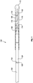
- FIG. 1 is an elevation side view and partial cross-section view of a guide wire 100 including features according to the present disclosure.
- Guide wire 100 may be adapted for insertion into a body lumen of a patient, for example a vein or artery.
- Guide wire 100 may include an elongate, relatively high strength proximal core portion 102 directly welded to a relatively flexible distal core portion 104 at weld joint 103.
- Weld joint 103 may be surrounded by a heat affected zone 105 as will be described below.
- Distal core portion 104 may include a tapered section 106, tapering to a smaller thickness in the distal direction.
- a helical coil 108 may be disposed about distal core section 104, which may be secured by its distal end to a distal end of shaping ribbon 110 (e.g., by solder) near rounded plug 112.
- a proximal end of shaping ribbon 110 may be secured (e.g., by solder) to distal core portion 104 at the same or a nearby location 114.
- a distal section 116 of coil 108 may be stretched in length to provide additional flexibility.
- Distal tip 118 of distal core portion 104 may be flattened into a rectangular cross-section, and may include a rounded tip 120 (e.g., solder) to prevent passage of distal tip 118 through any spaces between the coils of helical coil 108.
- FIG. 2 shows a simplified embodiment of another intravascular guide wire 200 including features of the present disclosure.
- Core portions 202 and 204 may be directly welded together at weld joint 203 during fabrication. Similar to guide wire 100, weld joint 203 includes a heat affected zone surrounding joint 203 as a result of the solid state deformation of the materials within this region.
- Portion 202 may comprise a material (e.g., stainless steel) having a relatively higher modulus of elasticity.
- a distal end of portion 202 may be directly joined through a weld (e.g., a butt weld) formed through solid state deformation to distal portion 204, which comprises a different material (e.g., nitinol), having a relatively lower modulus of elasticity.
- a weld e.g., a butt weld
- Distal portion 204 may include a flattened, shapable distal tip 218 which can be permanently deformed (e.g., by finger pressure) to create a tip that can be steered through a patient's vasculature. As shown, distal tip 218 may be bent or deformed into a J, L or similar bend 219. A tip coil 208 may be disposed over distal core portion 204.
- guide wires 100, 200 are merely two of many possible configurations, and other guide wire configurations including multiple segments that may be directly joined together by a weld formed under solid state deformation conditions are encompassed by the present disclosure.
- Distal core section 104, 204 may be made of a nickel-titanium alloy such as nitinol, a pseudoelastic alloy including about 30 atomic percent to about 52 atomic percent titanium, with the balance typically being nickel.
- a nickel-titanium alloy such as nitinol, a pseudoelastic alloy including about 30 atomic percent to about 52 atomic percent titanium, with the balance typically being nickel.
- up to about 10 atomic percent or up to about 3 atomic percent of one or more other alloying elements may be included.
- Other alloying elements include, but are not limited to iron, cobalt, vanadium, platinum, palladium, copper, and combinations thereof. Where copper, vanadium, or combinations thereof are included, each may be included in amounts of up to about 10 atomic percent in one embodiment. In one embodiment, where iron, cobalt, platinum, palladium, or combinations thereof are included, each may be included in amounts of up to about 3 atomic percent.
- a guide wire having a distal portion made at least in substantial part of such material can be readily advanced through tortuous arterial passageways with minimal risk of kinking. Such characteristics are similarly beneficial where the distal nitinol portion of the guide wire may be prolapsed, either deliberately or inadvertently.
- proximal portion 102, 202 of guide wire 100, 200 may typically be significantly stronger (i.e., having higher tensile strength) than pseudoelastic distal portion 104, 204.
- proximal portion 102, 202 may be formed of stainless steel (e.g., SAE 304 stainless steel).
- Other high strength materials including, but not limited to cobalt-chromium alloys such as MP35N may also be employed.
- the present methods may achieve direct joining of dissimilar metal materials to one another through a resistance, solid-state welding process in which the segments may be welded to one another.
- the welding process achieves the desired direct joint through solid state deformation of the ends of the two segments, without melting of either material.
- Such a method is particularly advantageous in the field of intravascular guide wires where the wire segments to be welded to one another are relatively small, such that known methods of solid state deformation weld bonding are unsuitable.
- welding processes capable of reliably joining dissimilar metals together without melting of either work piece are known.
- Such methods involve solid state bonding, rather than melting and fusion.
- a metallurgical bond is created while both materials remain in the solid state, typically through application of heat and pressure at the interface of the dissimilar metals.
- the earliest developed method known as forge welding, employs the blacksmith's technique of heating both work pieces near but below their respective melting points and forcing them together via successive hammer blows. Such a method is of course not suitable for welding fine wires together end-to-end, as may be required when joining multiple segments of a multi-segment intravascular guide wire.
- Another solid state joining method explosion welding, uses an engineered explosive charge to generate extremely high velocity and resulting high interfacial pressure between the pieces to be joined together. Such a method is employed in laminating sheet and plate materials, although it is not suitable for joining together fine wires.
- FIG. 3 shows embodiments including two segments, it will be understood that the methods herein described may similarly be employed to join more than two segments together, without the need to position any transition piece between the incompatible, dissimilar metal segments for compatibility purposes. For example, were three segments desired, two segments may be joined, followed by joining the resulting structure with a third segment.
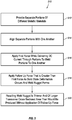
- the separate portions or segments are aligned (e.g., axially, end-to-end) with one another.
- a first force e.g., axial
- electrical e.g., DC, AC, or both
- a follow up force e.g., axial
- the weld nugget forms between the guide wire portions or segments.
- the resulting weld nugget is thinner and of a larger transverse cross-sectional area than would be produced without application of the follow up force.
- the method has been found to effectively and reliably directly join two dissimilar, incompatible elongate wire segments or portions to one another, while consistently achieving desired strength characteristics.
- the ends to be joined together may be prepared by flattening and smoothing the ends.
- Such end preparation may be achieved by grinding the mating ends just prior to alignment and the beginning of the welding process (i.e., when the first force is applied and electrical current is delivered through the segments). This may be so, even where the ends may have been smoothed and flattened previously, as removal of any oxide layers at this stage is desirable.
- the ends may be ground with a rotating disc covered with wet or dry sandpaper.
- An aqueous grinder coolant may serve to remove debris during the grinding step.
- Such a flattening and smoothing procedure acts to remove oxide from the wire ends, which oxide may otherwise interfere with the ability to achieve sufficient and consistent weld strength.
- the nitinol forms a titanium oxide layer
- the stainless steel includes a chromium oxide layer. It is beneficial to remove these oxide layers from the corresponding ends that are to be welded together. Removal of any oxide layers (e.g., preferably performed immediately prior to axial alignment and welding) minimizes contact resistance and reduces variability in contact resistance due to the presence of the oxide layers. This helps reduce variability in weld temperature from one weld to another, which helps in ensuring that no melting of either metal of the dissimilar wire segments occurs.
- preparation of the corresponding ends is performed “immediately prior to” or “just prior to” axial alignment and welding, it will be understood that some passage of time between preparation of the corresponding ends of the segments or portions to be joined together and axial alignment and butt welding of the segments or portions is acceptable so long as such time period is sufficiently short so as to prevent reformation of an oxide film over the prepared ends which could affect the contact resistance between said ends.
- preparation of the ends is performed within about 1 day of welding, within about 10 hours of welding, within about 1 hour of welding, within about 30 minutes of welding, within about 15 minutes of welding, within about 5 minutes of welding, within about 2 minutes of welding, or within about 1 minute of welding.
- the ends may be tightly pressed together (e.g., 698,48 MPa [100,000 psi] to 1378.95 MPa [200,000 psi]) through application of the first force prior to application of any electrical (e.g., DC, AC, or both) current so as to prevent any air from being present therebetween that might result in reformation of the oxide layers.
- any electrical e.g., DC, AC, or both
- resistance heating and the application of the forces associated with the welding process may be undertaken in an inert environment, which may further aid in preventing formation of any undesirable oxide layers that would interfere with contact resistance and maintaining weld temperature within the desired window.
- the baseline first force may be applied axially, and applied at any desired level, which may depend at least in part on the dimensions and material characteristics of the wire segments to be joined together.
- the force applied may be from 4.44 N (1 lb) to about 444 N (100 lbs), from 22.24 N (5 lbs) to 222.4 N (50 lbs), from 44.4 N (10 lbs) to 133.44 N (30 lbs), or from 66.72 (15 lbs) to 111.20 N (25 lbs).
- levels of force may result in pressures from 689.47 MPa (100,000 psi) to 1378.95 MPa (200,000 psi).
- the resulting pressure at the interface is 1034.21 MPa (150,000 psi).
- the baseline force and the cross-sectional thickness of the wire segments may result in a pressure at the interface of the segments from 241.31 MPa (35,000 psi) to 2757.90 MPa (400,000 psi), from 517.11 MPa (75,000 psi) to 1723.69 MPa (250,000 psi), or from 689.48 MPa (100,000 psi) to 1378.95 MPa (200,000 psi). Wire segments having relatively larger cross-sectional area may be processed at relatively higher force levels to provide similar pressures.
- the wire segments so joined may have about the same diameter (e.g., within about 25%, within about 10%, within about 5%, or within about 1% of one another). According to the present invention, the wire segment diameters may be approximately equal (e.g., both 0.33 mm [0.013 inch]).
- the baseline force may be applied while electrical (e.g., DC, AC, or both) current is applied to the segments.
- the value of the baseline force may be substantially constant over the period over which it is applied.
- electrical e.g., DC, AC, or both
- the regions adjacent the corresponding ends which are pressed together will begin to soften as the temperature increases. At some point, these regions will begin to collapse towards one another (i.e., solid state deformation) as setdown or axial displacement occurs, as a result of solid-state deformation.
- Electrical weld energy input may last from about 1 ms to about 100 ms, from about 5 ms to about 50 ms, or from about 10 ms to about 30 ms.
- the value of the applied current may depend on duration of the input, as well as the dimensions and material characteristics of the segments being joined together. In one embodiment, the applied current may be from about 0.01 kA to about 0.1 kA, from about 0.05 kA to about 0.08 kA, or from about 0.06 kA to about 0.07 kA. Of course, larger or smaller values than these ranges may be appropriate where the dimensions and/or material characteristics of the segments so dictate.
- Applied current may be DC current, AC current, or both.
- an embodiment may employ a high frequency inverter power source which may provide a DC pulse that may include high frequency AC overlaid on it.
- Such a power source may differ from standard AC in that the high frequency potential may not completely reverse polarity.
- the follow up force (e.g., axial) is applied after solid-state deformation (setdown) begins, but before such deformation has completed.
- the follow up force may be applied after some (e.g., most or all) of the electrical weld energy has been delivered (e.g., the electrical (e.g., DC, AC, or both) current delivery may have stopped). In one embodiment, there is a gap between when electrical weld energy input stops and the start of application of the follow up force.
- application of the follow up force may begin from about 0.5 ms to about 10 ms after the end of electrical (e.g., DC, AC, or both) current delivery, from about 2 ms to about 8 ms after the end of electrical (e.g., DC, AC, or both) current delivery, or from about 3 ms to about 5 ms after the end of electrical (e.g., DC, AC, or both) current delivery.
- electrical e.g., DC, AC, or both
- the value of the applied follow up force may depend on the material characteristics and dimensions (e.g., diameter) of the segments being directly joined together.
- the follow up force is from 88.96 N (20 lbs) to 266.89 N (60 lbs).
- a follow up force of 155.69 N (35 lbs) and a wire diameter of 0.33 mm (0.013 inch) inch results in a pressure of 1827.11 MPa (265,000 psi).
- the follow up force and/or the pressure provided by the follow up force is from about 10% greater to about 200% greater than the baseline force (or baseline pressure), from about 25% greater to about 150% greater than the baseline force (or baseline pressure), or from about 50% greater to about 100% greater than the baseline force (or baseline pressure).
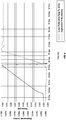
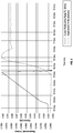
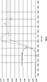
- FIGS. 4 and 5 plot electrical weld energy input and axial deformation profiles for directly butt welding a stainless steel proximal guide wire portion to a nitinol distal guide wire portion. Each portion had a diameter of 0.33 mm (0.013 inch).
- the profiles shown in FIG. 4 are without application of a follow up axial force, while the profiles shown in FIG. 5 are with application of a follow up axial force.
- FIG. 5 the total axial displacement or setdown was 1.0211 mm (0.0402 inch).
- the greater axial displacement value of FIG. 5 corresponds to a weld nugget of thinner cross-sectional thickness and greater transverse cross-sectional diameter than that of FIG. 4 .
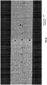
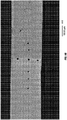
- Photographs of the two weld nuggets so formed are shown in FIGS. 8A and 8B .
- FIG. 6 shows the axial displacement profiles of FIGS. 4 and 5 on the same plot.
- the plotted profiles A and B begin substantially parallel to one another, with the divergence beginning at the point where the follow up axial force is applied in example B and not example A.
- a larger diameter weld nugget (associated with FIG. 5 ), including increased cross-sectional area at the interface between the dissimilar, incompatible materials serves to better accept such a transitory tensile load without pulling the weld apart or resulting in hidden damage within the weld nugget that might later lead to failure of the guide wire at the weld.
- application of the follow up force serves to squeeze and thereby extract heat from the weld nugget while substantially enlarging its cross-sectional area. Extraction of heat serves to decrease the temperature of the weld nugget, particularly its interface, thereby raising its strength and further improving its resistance to rebounding forces.
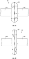
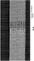
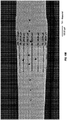
- FIG. 7A depicts an exemplary proximal and distal portion 302 and 304, respectively of a multi-segment guide wire 300 in the vicinity of the formed weld nugget.
- FIG. 7A corresponds to FIG. 4 , which does not include application of any follow up force.
- FIG. 7B depicts proximal and distal portions 302' and 304', respectively of a multi-segment guide wire 300' formed with application of a follow up axial force (corresponding to FIG. 5 ). These depictions correspond to the actual photographs shown in FIGS. 8A and 8B .
- the weld nugget 322 and 322' is seen disposed surrounding the interface where the respective proximal and distal portions are joined together.
- weld nugget 322' formed under conditions in which a larger follow up axial force is applied, exhibits a diameter D' that is at least about 5% greater, at least about 10% greater, or about 15% greater to about 25% greater than diameter D that would be produced without application of the follow up axial force.
- the diameter D' is about 20% larger in weld nugget 322' than diameter D of weld nugget 322
- the cross-sectional area of weld nugget 322' will be about 45% greater than the cross-sectional area of weld nugget 322. This significantly increased cross-sectional area (i.e., increased bonding area) better resists undesirable tensile loading due to mechanical rebounding.
- weld nugget 322' may have an average thickness T' that is from about 10% smaller to about 50% smaller, about 15% smaller to about 35% smaller, or about 20% smaller to about 30% smaller than thickness T that would be produced without application of the follow up axial force.
- the actual weld nuggets shown in FIGS. 8A and 8B exhibited an average thickness of 0.22 mm without application of a follow up force, and an average thickness of 0.15 mm with application of a follow up force.
- the resulting diameter shown in FIG. 8B was 20% larger than that shown in FIG. 8A , providing an increase in cross-sectional bonded surface area of 45%.
- FIGS. 4-8B While the embodiments described in FIGS. 4-8B are shown as being carried out under conditions in which the corresponding ends of the segments or portions are shaped and oriented to provide a butt joint as a result of the weld, it will be understood that other welded joint configurations, including but not limited to butt joints, overlap joints, joints including corresponding oblique angled ends, and combinations thereof may also be employed. Various alternative joint configurations that may be employed are shown in U.S. Patent No 7,998,090 .
- the weld nugget disposed therebetween can be removed by grinding.
- the majority of the excess weld nugget material extending laterally beyond the diameter of the adjacent proximal and distal segments may be ground away in a centerless grinding operation. Any remaining excess metal may be removed while grinding the entire distal core wire profile.
- multi-segment guide wires formed as described herein with application of an increased follow up force exhibit characteristics allowing them to be identified as having been produced according to such methods herein described.
- the resulting multi-segment guide wire includes a heat affected zone corresponding to the location of the weld nugget.
- a multi-segment guide wire may have a heat affected zone that has a thickness of less than about 0.20 mm, less than about 0.18 mm, or from about 0.15 mm to about 0.18 mm in thickness.
- Such reduced thickness heat affected zones provide improved kink resistance.
- the heat affected zone may also exhibit unique hardness characteristics as a result of the heat affected zone having undergone greater levels of solid state deformation arising from the follow up force. Specifically, the heat affected zone is expected to be narrower and exhibit a lesser degree of softening as compared with welds created without a follow up force. ]
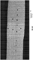
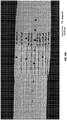
- Comparative measurements of the heat affected zone were carried out on multi-segment guide wires according to the present disclosure as compared to Terumo guide wires. Measurement of microhardness impressions within the stainless steel portion, the nickel-titanium portion, and the heat affected weld zone therebetween were taken using Vickers hardness testing. Each Vickers hardness measurement was made using 100 grams of force (HV100). Three measurements within each region were obtained. The results are shown in Tables 1A and 1B. AVI, AV2, and AV3 refer to multi-segment guide wires according to the present disclosure. T1, T2, and T3 refer to hardness tested Terumo guide wires.
- FIGS. 9A-9E show images of the multi-segment guide wires AV1-AV3 that were measured.
- FIGS. 10A-10F show images of the Terumo guide wires T1-T3.
- Comparative strength testing was performed on multi-segment guide wires formed according to methods described above in conjunction with FIGS. 4-5 .
- Multi-segment guide wires formed with and without application of a follow up axial force were subjected to destructive rotary bend testing (essentially a low-cycle fatigue test).
- Tensile testing may not always correlate to actual performance in bending conditions (which exist during use of the guide wires). For example, while a welding process may produce components that exhibit acceptable, even high tensile test values, the inventors have found that some such welded components perform poorly when subjected to bending.
- Rotary bend testing better approximates use conditions, and provides a better measurement of weld strength during use.
- the weld of each guide wire was simultaneously bent to a 90° and rotated one complete revolution (360°) in order to challenge all locations around the weld joint perimeter.
- the test design ensures that the weld interface will reside near the onset of the 90° bend, and thus participate in the curvature.
- the applied force incrementally increases during testing, the radius of curvature within the turn becomes tighter, thereby increasing the bend severity and further challenging the weld interface.
- Each rotary bend test result was recorded in psi, representing the actual air pressure being applied, at the moment of failure, to a piston used to apply the force.
- Each of groups A and B were formed in a manner similar to one another, other than application of the follow up axial force in group B. Manufacturing conditions were as described above in conjunction with FIGS. 4-5 .
- Group A had a significantly lower mean strength value, and the minimum strength value was only 2.0 psi, which is below a desired performance specification of 2.2 psi.
- Group B included a minimum strength value of 2.9 psi, well above the desired minimum of 2.2 psi.
- Cpk is a commonly employed index that quantifies how capable a process is of consistently meeting the desired specification. Higher values of Cpk correspond to better capability in consistently meeting the desired specification.
- Cpk is calculated by dividing the difference between the mean value and the specification by 3 standard deviations (i.e., (mean - 2.2)/(3x stdev)). As is readily apparent from Table 2, the Cpk value for group B is nearly double the Cpk value for group A.
- the comparative testing thus indicates that significantly greater consistency with respect to desired strength characteristics is achieved when forming the guide wires with application of a follow up axial force. This is particularly important where the guide wire exhibiting sub specification strength characteristics may not be readily recognizable through non-destructive quality control mechanisms.
- the inventive method of manufacture thus increases consistency within the manufactured guide wires, while decreasing any incidence of passing sub specification parts.
Landscapes
- Engineering & Computer Science (AREA)
- Mechanical Engineering (AREA)
- Health & Medical Sciences (AREA)
- Life Sciences & Earth Sciences (AREA)
- Heart & Thoracic Surgery (AREA)
- General Health & Medical Sciences (AREA)
- Anesthesiology (AREA)
- Biomedical Technology (AREA)
- Biophysics (AREA)
- Hematology (AREA)
- Animal Behavior & Ethology (AREA)
- Pulmonology (AREA)
- Public Health (AREA)
- Veterinary Medicine (AREA)
- Media Introduction/Drainage Providing Device (AREA)
- Pressure Welding/Diffusion-Bonding (AREA)
- Surgical Instruments (AREA)
- Arc Welding In General (AREA)
Claims (15)
- Mehrfach segmentierter Intravaskular-Führungsdraht (200) umfassend:einen länglichen ersten Abschnitt (202) umfassend ein erstes metallisches Material;einen länglichen zweiten Abschnitt (204) umfassend ein unterschiedliches metallisches Material, wobei der erste und zweite längliche Abschnitt (202, 204) durch eine Festkörperschweißung mit den Enden aneinander direkt miteinander verbunden sind, wobei der erste und zweite längliche Abschnitt (202, 204) einen Drahtdurchmesser von etwa 0,33 mm aufweisen; und gekennzeichnet durch:
eine Wärmeeinflusszone, die eine Schnittstelle der Schweißung umgibt, wobei der erste und zweite Abschnitt miteinander verbunden sind, wobei die Wärmeeinflusszone eine durchschnittliche Dicke von 0,126 mm bis 0,20 mm aufweist. - Mehrfach segmentierter Intravaskular-Führungsdraht (200) nach Anspruch 1, wobei die Wärmeeinflusszone eine durchschnittliche Dicke von 0,126 mm bis 0,18 mm aufweist.
- Mehrfach segmentierter Intravaskular-Führungsdraht (200) nach Anspruch 1, wobei die Wärmeeinflusszone eine durchschnittliche Dicke von 0,15 mm bis 0,18 mm aufweist.
- Mehrfach segmentierter Intravaskular-Führungsdraht (200) nach Anspruch 1, wobei ein Abschnitt (204) eine Nickel-Titan-Legierung umfasst, und der andere Abschnitt (202) Edelstahl umfasst.
- Mehrfach segmentierter Intravaskular-Führungsdraht (200) nach Anspruch 1, wobei ein Abschnitt (204) eine Nickel-Titan-Legierung umfasst.
- Mehrfach segmentierter Intravaskular-Führungsdraht (200) nach Anspruch 1, wobei ein Abschnitt (202) Edelstahl umfasst.
- Mehrfach segmentierter Intravaskular-Führungsdraht (200) nach Anspruch 1, wobei ein Abschnitt (204) eine Nickel-Titan-Legierung umfasst, und der andere Abschnitt (204) Edelstahl oder eine Kobalt-Chrom-Legierung umfasst.
- Verfahren zum Verbinden von Teilen (202, 204) unterschiedlicher metallischer Materialien, wobei ein Teil (204) eine Nickel-Titan-Legierung umfasst, und ein anderes Teil (202) Edelstahl oder eine Kobalt-Chrom-Legierung umfasst, wobei das Verfahren umfasst:Bereitstellen von einer Mehrzahl von zunächst getrennten Teilen (202, 204), welche Teile (202, 204) unterschiedliche metallische Materialien umfassen, wobei jedes der Teile (202, 204) einen Drahtdurchmesser von etwa 0,33 mm aufweist;Ausrichten der getrennten Teile (202, 204);Ausüben einer ersten Kraft auf die ausgerichteten Teile (202, 204), während ein elektrischer Strom durch die getrennten Teile (202, 204) geleitet wird, um die getrennten Teile (202, 204) miteinander zu verschweißen; und ferner gekennzeichnet durch:
Ausüben einer Folgekraft von 88,96 N (20 Lbs) bis 266,89 N (60 Lbs), welche größer als die erste Kraft ist, wenn eine Verformung der Teile (202, 204) stattfindet, und sich ein Schweißpunkt zwischen den Teilen (202, 204) bildet, um einen Schweißpunkt zu erzeugen, der dünner ist und einen größeren Querschnittsbereich aufweist als was ohne Ausüben der Folgekraft erzeugt werden würde, so dass eine Wärmeeinflusszone, die einem Ort des Schweißpunktes entspricht, eine durchschnittliche Dicke von 0,126 mm bis 0,20 mm aufweist. - Verfahren nach Anspruch 8, wobei die Folgekraft um ab 10 % größer bis 200 % größer als die erste Kraft, bevorzugt um ab 25 % größer bis 150 % größer als die erste Kraft, und eher bevorzugt um ab 50 % größer bis 100 % größer als die erste Kraft ist.
- Verfahren nach Anspruch 8, wobei die Folgekraft ausgeübt wird, nachdem die Abgabe des elektrischen Stroms beendet worden ist und bevor die Verformung vollendet ist.
- Verfahren nach Anspruch 8, wobei die Teile (202, 204) länglich sind und mit den Enden aneinander zu verbinden sind, wobei das Verfahren ferner ein Vorbereiten der entsprechenden Enden der länglichen Teile (202, 204) umfasst, um die Enden vor dem Ausrichten und Schweißen zu glätten und abzuflachen.
- Verfahren nach Anspruch 8, wobei der Schweißpunkt einen Durchmesser aufweist, der um mindestens 5 % größer, bevorzugt um mindestens 10 % größer, eher bevorzugt um ab 15 % größer bis 25 % größer ist als der Durchmesser, der ohne Ausüben der Folgekraft erzeugt werden würde.
- Verfahren nach Anspruch 8, wobei der Schweißpunkt eine durchschnittliche Dicke aufweist, die um ab 10 % kleiner bis 50 % kleiner, bevorzugt um ab 15 % kleiner bis 35 % kleiner, und eher bevorzugt um ab 20 % kleiner bis 30 % kleiner ist als die Dicke, die ohne Ausüben der Folgekraft erzeugt werden würde.
- Mehrfach segmentierter Intravaskular-Führungsdraht (200) erwähnt in Anspruch 1, wobei der Führungsdraht (200) durch ein Verfahren umfassend Folgendes gebildet ist:Bereitstellen einer Mehrzahl zunächst getrennter Teile (202, 204), welche Teile (202, 204) unterschiedliche metallische Materialien umfassen;Ausrichten der getrennten Teile (202, 204);Ausüben einer ersten Kraft auf die ausgerichteten Teile (202, 204), während ein elektrischer Strom durch die getrennten Teile (202, 204) geleitet wird, um die getrennten Teile (202, 204) miteinander zu verschweißen; undAusüben einer Folgekraft, die größer als die erste Kraft ist, wenn die Verformung der Teile (202, 204) stattfindet und sich ein Schweißpunkt zwischen den Teilen (202, 204) bildet, um einen Schweißpunkt zu erzeugen, der dünner ist und einen größeren transversalen Querschnittsbereich aufweist, als was ohne Ausüben der Folgekraft erzeugt werden würde.
- Mehrfach segmentierter Führungsdraht nach Anspruch 14, wobei der nach dem Verfahren erzeugte Führungsdraht (200) eine höhere mittlere Festigkeit und höhere Cpk-Werte im Vergleich zu ohne Ausüben von Folgekraft erzeugten Führungsdrähten aufweist, wobei Cpk ein Index ist, der quantifiziert, wie hohe Fähigkeiten ein Verfahren aufweist, um die gewünschte Spezifikation dauerhaft zu erfüllen.
Applications Claiming Priority (3)
| Application Number | Priority Date | Filing Date | Title |
|---|---|---|---|
| US13/744,276 US9636485B2 (en) | 2013-01-17 | 2013-01-17 | Methods for counteracting rebounding effects during solid state resistance welding of dissimilar materials |
| EP14702708.0A EP2945768B1 (de) | 2013-01-17 | 2014-01-16 | Verfahren zur bekämpfung von rückpralleffekten beim festkörperwiderstandsschweissen von unterschiedlichen materialien |
| PCT/US2014/011777 WO2014113527A1 (en) | 2013-01-17 | 2014-01-16 | Methods for counteracting rebounding effects during solid state resistance welding of dissimilar materials |
Related Parent Applications (1)
| Application Number | Title | Priority Date | Filing Date |
|---|---|---|---|
| EP14702708.0A Division EP2945768B1 (de) | 2013-01-17 | 2014-01-16 | Verfahren zur bekämpfung von rückpralleffekten beim festkörperwiderstandsschweissen von unterschiedlichen materialien |
Publications (2)
| Publication Number | Publication Date |
|---|---|
| EP3192608A1 EP3192608A1 (de) | 2017-07-19 |
| EP3192608B1 true EP3192608B1 (de) | 2019-11-27 |
Family
ID=50033826
Family Applications (2)
| Application Number | Title | Priority Date | Filing Date |
|---|---|---|---|
| EP17159014.4A Active EP3192608B1 (de) | 2013-01-17 | 2014-01-16 | Mehrfach segementierter intravaskular-führungsdraht mit einem schweissen; verfahren zur bekämpfung von rückpralleffekten beim festkörperwiderstandsschweissen von unterschiedlichen materialien |
| EP14702708.0A Not-in-force EP2945768B1 (de) | 2013-01-17 | 2014-01-16 | Verfahren zur bekämpfung von rückpralleffekten beim festkörperwiderstandsschweissen von unterschiedlichen materialien |
Family Applications After (1)
| Application Number | Title | Priority Date | Filing Date |
|---|---|---|---|
| EP14702708.0A Not-in-force EP2945768B1 (de) | 2013-01-17 | 2014-01-16 | Verfahren zur bekämpfung von rückpralleffekten beim festkörperwiderstandsschweissen von unterschiedlichen materialien |
Country Status (5)
| Country | Link |
|---|---|
| US (6) | US9636485B2 (de) |
| EP (2) | EP3192608B1 (de) |
| JP (1) | JP6351628B2 (de) |
| CN (1) | CN105142845B (de) |
| WO (1) | WO2014113527A1 (de) |
Families Citing this family (16)
| Publication number | Priority date | Publication date | Assignee | Title |
|---|---|---|---|---|
| US9061088B2 (en) | 2012-02-02 | 2015-06-23 | Abbott Cardiovascular Systems, Inc. | Guide wire core wire made from a substantially titanium-free alloy for enhanced guide wire steering response |
| US9636485B2 (en) | 2013-01-17 | 2017-05-02 | Abbott Cardiovascular Systems, Inc. | Methods for counteracting rebounding effects during solid state resistance welding of dissimilar materials |
| US20150045695A1 (en) * | 2013-08-06 | 2015-02-12 | Abbott Cardiovascular Systems, Inc. | Guide wire with core made from low-modulus cobalt-chromium alloy |
| US10071229B2 (en) | 2015-04-14 | 2018-09-11 | Abbott Cardiovascular Systems, Inc. | Mechanisms for improving the stiffness transition across a dissimilar metal weld joint |
| CN109072347A (zh) | 2016-04-20 | 2018-12-21 | 奥科宁克有限公司 | 铝、钴、铁和镍的fcc材料及由其制成的产物 |
| WO2017184778A1 (en) | 2016-04-20 | 2017-10-26 | Arconic Inc. | Fcc materials of aluminum, cobalt and nickel, and products made therefrom |
| US11278701B2 (en) | 2016-10-13 | 2022-03-22 | Lake Region Manufacturing, Inc. | Apparatus including multiple joined hypotubes and method of making same |
| JP6596470B2 (ja) * | 2017-07-20 | 2019-10-23 | トクセン工業株式会社 | 医療処置具用ワイヤ及びガイドワイヤ |
| CN111315285B (zh) * | 2017-08-31 | 2023-06-06 | 皇家飞利浦有限公司 | 具有集成式近侧锁定特征的感测导丝 |
| EP4112219A4 (de) * | 2020-03-30 | 2023-03-08 | TERUMO Kabushiki Kaisha | Führungsdraht |
| JP7758473B2 (ja) * | 2021-04-07 | 2025-10-22 | 朝日インテック株式会社 | ガイドワイヤ、および、ガイドワイヤの製造方法 |
| CN115068789B (zh) * | 2021-10-22 | 2024-03-01 | 美度可医疗科技(上海)有限公司 | 一种平滑的异金属核芯导丝 |
| US12538908B2 (en) | 2021-11-23 | 2026-02-03 | Tim Drinkard | Retractable barb fish hook |
| US20240374871A1 (en) * | 2023-05-11 | 2024-11-14 | Abbott Cardiovascular Systems Inc. | Twisted guidewire |
| CN117773296A (zh) * | 2024-01-18 | 2024-03-29 | 南昌大学 | 一种镍钛合金丝与不锈钢丝的焊接方法 |
| CN121061447B (zh) * | 2025-10-13 | 2026-04-14 | 中建海峡建设发展有限公司 | 一种市政施工用金属管道焊接装置 |
Family Cites Families (94)
| Publication number | Priority date | Publication date | Assignee | Title |
|---|---|---|---|---|
| US1793218A (en) * | 1928-07-16 | 1931-02-17 | Jones & Laughlin Steel Corp | Apparatus for making welded pipe |
| US2323660A (en) * | 1942-03-07 | 1943-07-06 | Mallory & Co Inc P R | Flash-arc welding |
| US3259969A (en) * | 1963-01-22 | 1966-07-12 | Central Cable Corp | Method of making butt welded joints |
| US3660176A (en) * | 1970-02-10 | 1972-05-02 | Armco Steel Corp | Precipitation-hardenable stainless steel method and product |
| US3961153A (en) * | 1974-05-24 | 1976-06-01 | Trw Inc. | Machine for fabricating a wire network |
| DE2538295A1 (de) | 1975-08-28 | 1977-03-10 | Bosch Gmbh Robert | Verfahren zum herstellen einer elektrisch leitenden und mechanisch festen verbindung von aluminiumleitern an kupferkommutatoren |
| US4358658A (en) | 1980-12-05 | 1982-11-09 | The United States Of America As Represented By The United States Department Of Energy | Laser weld jig |
| CH660882A5 (de) | 1982-02-05 | 1987-05-29 | Bbc Brown Boveri & Cie | Werkstoff mit zweiweg-gedaechtniseffekt und verfahren zu dessen herstellung. |
| DE3381586D1 (de) * | 1982-06-18 | 1990-06-28 | Scm Corp | Verfahren zur herstellung von dispersionsverfestigten metallkoerpern sowie diese koerper. |
| US4934380A (en) * | 1987-11-27 | 1990-06-19 | Boston Scientific Corporation | Medical guidewire |
| US4922924A (en) | 1989-04-27 | 1990-05-08 | C. R. Bard, Inc. | Catheter guidewire with varying radiopacity |
| JPH03243296A (ja) | 1990-02-22 | 1991-10-30 | Kobe Steel Ltd | ステンレス鋼用フラックス入りワイヤ |
| US5135503A (en) | 1990-05-16 | 1992-08-04 | Advanced Cardiovascular Systems, Inc. | Shaping ribbon for guiding members |
| US5341818A (en) * | 1992-12-22 | 1994-08-30 | Advanced Cardiovascular Systems, Inc. | Guidewire with superelastic distal portion |
| EP0491349B1 (de) | 1990-12-18 | 1998-03-18 | Advanced Cardiovascular Systems, Inc. | Verfahren zur Herstellung eines super-elastischen Führungsteils |
| DE69212365T2 (de) * | 1991-04-09 | 1997-01-02 | Furukawa Electric Co Ltd | Verbundene Teile von Ni-Ti-Legierugen mit verschiedenen Metallen und Verbindungsverfahren dafür |
| US5354623A (en) | 1991-05-21 | 1994-10-11 | Cook Incorporated | Joint, a laminate, and a method of preparing a nickel-titanium alloy member surface for bonding to another layer of metal |
| US5415178A (en) | 1991-08-26 | 1995-05-16 | Target Therapeutics | Extendable guidewire assembly |
| US5630840A (en) | 1993-01-19 | 1997-05-20 | Schneider (Usa) Inc | Clad composite stent |
| US5772609A (en) * | 1993-05-11 | 1998-06-30 | Target Therapeutics, Inc. | Guidewire with variable flexibility due to polymeric coatings |
| US5769796A (en) * | 1993-05-11 | 1998-06-23 | Target Therapeutics, Inc. | Super-elastic composite guidewire |
| JP3343394B2 (ja) * | 1993-05-24 | 2002-11-11 | 中央精機株式会社 | アルミ合金のアプセットバット溶接方法 |
| US5720300A (en) | 1993-11-10 | 1998-02-24 | C. R. Bard, Inc. | High performance wires for use in medical devices and alloys therefor |
| US5488959A (en) * | 1993-12-27 | 1996-02-06 | Cordis Corporation | Medical guidewire and welding process |
| US6736843B1 (en) | 1994-07-25 | 2004-05-18 | Advanced Cardiovascular Systems, Inc. | Cylindrically-shaped balloon-expandable stent |
| DK0729765T3 (da) * | 1995-03-02 | 2000-10-16 | Schneider Europ Gmbh | Fremgangsmåde til fremstilling af en styretråd |
| US5916178A (en) | 1995-03-30 | 1999-06-29 | Medtronic, Inc. | Steerable high support guidewire with thin wall nitinol tube |
| US5724989A (en) | 1995-06-20 | 1998-03-10 | The Microspring Company, Inc. | Radiopaque medical devices |
| US6019736A (en) * | 1995-11-06 | 2000-02-01 | Francisco J. Avellanet | Guidewire for catheter |
| US6000601A (en) | 1996-10-22 | 1999-12-14 | Boston Scientific Corporation | Welding method |
| US6001068A (en) | 1996-10-22 | 1999-12-14 | Terumo Kabushiki Kaisha | Guide wire having tubular connector with helical slits |
| US5851192A (en) | 1997-06-24 | 1998-12-22 | Asahi Intecc Co., Ltd. | Connecting structure of the guide wire used for medical treatment |
| US5980471A (en) | 1997-10-10 | 1999-11-09 | Advanced Cardiovascular System, Inc. | Guidewire with tubular connector |
| US5951886A (en) | 1997-12-23 | 1999-09-14 | Ptr Precision Technologies | Apparatus for electron beam welding at atmospheric pressure |
| US20060047223A1 (en) | 2004-08-31 | 2006-03-02 | Ryan Grandfield | Apparatus and method for joining stainless steel guide wire portion to nitinol portion, without a hypotube |
| US6306105B1 (en) | 1998-05-14 | 2001-10-23 | Scimed Life Systems, Inc. | High performance coil wire |
| US6387060B1 (en) | 1998-06-17 | 2002-05-14 | Advanced Cardiovascular Systems, Inc. | Composite radiopaque intracorporeal product |
| US6267776B1 (en) | 1999-05-03 | 2001-07-31 | O'connell Paul T. | Vena cava filter and method for treating pulmonary embolism |
| US6645159B1 (en) | 1999-11-30 | 2003-11-11 | Advanced Cardiovascular Systems, Inc. | Wire joint and method |
| WO2001098018A1 (de) | 2000-06-21 | 2001-12-27 | Siemens Aktiengesellschaft | Verbindungstechnik zwischen formgedächtnis-material und stahl- oder kupfermaterial |
| US6669652B2 (en) | 2000-12-21 | 2003-12-30 | Advanced Cardiovascular Systems, Inc. | Guidewire with tapered distal coil |
| JP2003049249A (ja) | 2001-08-09 | 2003-02-21 | Hitachi Metals Ltd | ガイドワイヤ用材料及びその製造方法 |
| JP4199446B2 (ja) | 2001-09-12 | 2008-12-17 | 株式会社日立製作所 | 摩擦攪拌接合装置 |
| US6918882B2 (en) | 2001-10-05 | 2005-07-19 | Scimed Life Systems, Inc. | Guidewire with stiffness blending connection |
| DE60208057T2 (de) | 2001-10-05 | 2006-06-29 | Boston Scientific Ltd. | Kompositführungsdraht |
| US6799067B2 (en) * | 2001-12-26 | 2004-09-28 | Advanced Cardiovascular Systems, Inc. | MRI compatible guide wire |
| US6702762B2 (en) | 2001-12-27 | 2004-03-09 | Advanced Cardiovascular Systems, Inc. | Apparatus and method for joining two guide wire core materials without a hypotube |
| JP4136370B2 (ja) | 2001-12-28 | 2008-08-20 | トクセン工業株式会社 | 医療用ガイドワイヤ用芯材の製造方法および医療用ガイドワイヤ |
| US7126078B2 (en) * | 2002-02-28 | 2006-10-24 | Emcore Corporation | Sub-micron adjustable mount for supporting a component and method |
| JP4809575B2 (ja) | 2002-03-29 | 2011-11-09 | 太平洋セメント株式会社 | 土木構造物用セメント組成物及びこれを用いたコンクリート製品 |
| US6968237B2 (en) | 2002-05-22 | 2005-11-22 | Pacesetter, Inc. | Implantable coronary sinus lead and lead system |
| JP2004065796A (ja) | 2002-08-08 | 2004-03-04 | Terumo Corp | ガイドワイヤ |
| JP5089517B2 (ja) * | 2002-08-08 | 2012-12-05 | テルモ株式会社 | ガイドワイヤ |
| JP4203358B2 (ja) * | 2002-08-08 | 2008-12-24 | テルモ株式会社 | ガイドワイヤ |
| JP4375951B2 (ja) | 2002-08-08 | 2009-12-02 | テルモ株式会社 | ガイドワイヤ |
| US7722551B2 (en) | 2002-08-09 | 2010-05-25 | Terumo Kabushiki Kaisha | Guide wire |
| JP4138582B2 (ja) * | 2002-08-23 | 2008-08-27 | テルモ株式会社 | ガイドワイヤ |
| JP2006501926A (ja) | 2002-10-04 | 2006-01-19 | アドバンスド、カーディオバスキュラー、システムズ、インコーポレーテッド | 医療機器用の放射線不透過性ニチノール合金 |
| US6866642B2 (en) | 2002-11-25 | 2005-03-15 | Advanced Cardiovascular Systems, Inc. | Enhanced method for joining two core wires |
| US20040116831A1 (en) | 2002-12-13 | 2004-06-17 | Scimed Life Systems, Inc. | Distal protection guidewire with nitinol core |
| US7182735B2 (en) | 2003-02-26 | 2007-02-27 | Scimed Life Systems, Inc. | Elongated intracorporal medical device |
| JP4416421B2 (ja) | 2003-03-18 | 2010-02-17 | テルモ株式会社 | ガイドワイヤおよびその製造方法 |
| US6875949B2 (en) * | 2003-03-19 | 2005-04-05 | Edison Welding Institute | Method of welding titanium and titanium based alloys to ferrous metals |
| JP4677205B2 (ja) | 2003-07-17 | 2011-04-27 | テルモ株式会社 | ガイドワイヤ |
| US8048369B2 (en) | 2003-09-05 | 2011-11-01 | Ati Properties, Inc. | Cobalt-nickel-chromium-molybdenum alloys with reduced level of titanium nitride inclusions |
| US7785273B2 (en) | 2003-09-22 | 2010-08-31 | Boston Scientific Scimed, Inc. | Guidewire with reinforcing member |
| JP4376048B2 (ja) * | 2003-12-18 | 2009-12-02 | テルモ株式会社 | ガイドワイヤ |
| CN100558423C (zh) | 2003-12-18 | 2009-11-11 | 泰尔茂株式会社 | 导向线 |
| US7824345B2 (en) | 2003-12-22 | 2010-11-02 | Boston Scientific Scimed, Inc. | Medical device with push force limiter |
| US7164094B2 (en) * | 2004-01-12 | 2007-01-16 | General Electric Company | Apparatus and method for electrofriction welding |
| US7993387B2 (en) * | 2004-05-14 | 2011-08-09 | Boston Scientific Scimed, Inc. | Stent with reduced weld profiles and a closed-end wire configuration |
| EP1788926B1 (de) | 2004-06-22 | 2016-11-02 | Lake Region Manufacturing, Inc. | Führungsdraht mit variabler steifheit |
| US7998090B2 (en) | 2004-08-31 | 2011-08-16 | Abbott Cardiovascular Systems Inc. | Guide wire with core having welded wire segments |
| JP4734015B2 (ja) | 2005-04-15 | 2011-07-27 | テルモ株式会社 | ガイドワイヤの製造方法 |
| US20060259063A1 (en) | 2005-04-25 | 2006-11-16 | Bates Brian L | Wire guides having distal anchoring devices |
| US7627382B2 (en) | 2005-05-25 | 2009-12-01 | Lake Region Manufacturing, Inc. | Medical devices with aromatic polyimide coating |
| US8267872B2 (en) | 2005-07-07 | 2012-09-18 | St. Jude Medical, Cardiology Division, Inc. | Steerable guide wire with torsionally stable tip |
| US20070185415A1 (en) | 2005-07-07 | 2007-08-09 | Ressemann Thomas V | Steerable guide wire with torsionally stable tip |
| US7683288B2 (en) * | 2005-08-12 | 2010-03-23 | Thermatool Corp. | System and method of computing the operating parameters of a forge welding machine |
| US20070244413A1 (en) * | 2006-04-12 | 2007-10-18 | Medtronic Vascular, Inc. | Medical guidewire tip construction |
| US7731669B2 (en) * | 2006-05-12 | 2010-06-08 | Concert Medical, Llc | Guidewire formed with composite construction and method for making the same |
| US8695868B2 (en) * | 2006-08-30 | 2014-04-15 | Fluor Technologies Corporation | Compositions and methods for dissimilar material welding |
| US7896820B2 (en) | 2006-12-26 | 2011-03-01 | Terumo Kabushiki Kaisha | Guide wire |
| JP4917900B2 (ja) | 2007-01-12 | 2012-04-18 | テルモ株式会社 | ガイドワイヤ用中間部材およびガイドワイヤ |
| JP4277117B2 (ja) * | 2007-03-29 | 2009-06-10 | 福井県 | ニッケル・チタン合金材料及び純チタン材料の異種金属接合体並びにその接合方法 |
| WO2008123402A1 (ja) | 2007-03-29 | 2008-10-16 | Fukui Prefectural Government | 異種金属接合体及びその接合方法 |
| US8105246B2 (en) * | 2007-08-03 | 2012-01-31 | Boston Scientific Scimed, Inc. | Elongate medical device having enhanced torque and methods thereof |
| WO2010033873A1 (en) | 2008-09-19 | 2010-03-25 | Fort Wayne Metals Research Products Corporation | Fatigue damage resistant wire and method of production thereof |
| US20120283700A1 (en) * | 2011-05-04 | 2012-11-08 | Abbott Cardiovascular Systems Inc. | Multi-metal guide wire coil |
| US20120305533A1 (en) | 2011-06-02 | 2012-12-06 | Taylor Winfield Technologies, Inc. | Forced freeze welding of advanced high strength steels |
| JP5876244B2 (ja) * | 2011-07-29 | 2016-03-02 | Jfeテクノワイヤ株式会社 | 溶接接合方法 |
| US20130189023A1 (en) * | 2011-12-21 | 2013-07-25 | Alcoa Inc. | Apparatus and methods for joining dissimilar materials |
| US9061088B2 (en) | 2012-02-02 | 2015-06-23 | Abbott Cardiovascular Systems, Inc. | Guide wire core wire made from a substantially titanium-free alloy for enhanced guide wire steering response |
| US9636485B2 (en) | 2013-01-17 | 2017-05-02 | Abbott Cardiovascular Systems, Inc. | Methods for counteracting rebounding effects during solid state resistance welding of dissimilar materials |
-
2013
- 2013-01-17 US US13/744,276 patent/US9636485B2/en active Active
-
2014
- 2014-01-16 WO PCT/US2014/011777 patent/WO2014113527A1/en not_active Ceased
- 2014-01-16 EP EP17159014.4A patent/EP3192608B1/de active Active
- 2014-01-16 EP EP14702708.0A patent/EP2945768B1/de not_active Not-in-force
- 2014-01-16 JP JP2015553815A patent/JP6351628B2/ja active Active
- 2014-01-16 CN CN201480010026.2A patent/CN105142845B/zh not_active Expired - Fee Related
-
2017
- 2017-04-24 US US15/494,970 patent/US10717145B2/en active Active
-
2020
- 2020-06-10 US US16/897,784 patent/US11440127B2/en active Active
-
2022
- 2022-07-06 US US17/858,343 patent/US11931817B2/en active Active
-
2024
- 2024-02-07 US US18/435,259 patent/US12325083B2/en active Active
-
2025
- 2025-05-15 US US19/209,515 patent/US20250269458A1/en active Pending
Non-Patent Citations (1)
| Title |
|---|
| None * |
Also Published As
| Publication number | Publication date |
|---|---|
| US20220331896A1 (en) | 2022-10-20 |
| JP6351628B2 (ja) | 2018-07-04 |
| US20200298332A1 (en) | 2020-09-24 |
| US11931817B2 (en) | 2024-03-19 |
| US11440127B2 (en) | 2022-09-13 |
| US20140200555A1 (en) | 2014-07-17 |
| EP2945768A1 (de) | 2015-11-25 |
| WO2014113527A1 (en) | 2014-07-24 |
| EP2945768B1 (de) | 2017-03-08 |
| CN105142845B (zh) | 2019-03-22 |
| WO2014113527A4 (en) | 2014-08-28 |
| EP3192608A1 (de) | 2017-07-19 |
| US9636485B2 (en) | 2017-05-02 |
| US20250269458A1 (en) | 2025-08-28 |
| CN105142845A (zh) | 2015-12-09 |
| US20240181556A1 (en) | 2024-06-06 |
| US20170225260A1 (en) | 2017-08-10 |
| JP2016510261A (ja) | 2016-04-07 |
| US12325083B2 (en) | 2025-06-10 |
| US10717145B2 (en) | 2020-07-21 |
Similar Documents
| Publication | Publication Date | Title |
|---|---|---|
| US12325083B2 (en) | Methods for counteracting rebounding effects during solid state resistance welding of dissimilar materials | |
| US11129970B2 (en) | Mechanisms for improving the stiffness transition across a dissimilar metal weld joint | |
| EP2724745B1 (de) | Verfahren zum Verbinden von Führungsdrahtsegmenten | |
| US20150045695A1 (en) | Guide wire with core made from low-modulus cobalt-chromium alloy | |
| US20160279391A1 (en) | Solid state methods for joining dissimilar metal guidewire segments without the use of tertiary material | |
| US20080306453A1 (en) | Coupling wire guide and method for making same | |
| JP2004181089A (ja) | ガイドワイヤ | |
| JP2023104105A (ja) | 結合体及びその製造方法 |
Legal Events
| Date | Code | Title | Description |
|---|---|---|---|
| PUAI | Public reference made under article 153(3) epc to a published international application that has entered the european phase |
Free format text: ORIGINAL CODE: 0009012 |
|
| STAA | Information on the status of an ep patent application or granted ep patent |
Free format text: STATUS: THE APPLICATION HAS BEEN PUBLISHED |
|
| AC | Divisional application: reference to earlier application |
Ref document number: 2945768 Country of ref document: EP Kind code of ref document: P |
|
| AK | Designated contracting states |
Kind code of ref document: A1 Designated state(s): AL AT BE BG CH CY CZ DE DK EE ES FI FR GB GR HR HU IE IS IT LI LT LU LV MC MK MT NL NO PL PT RO RS SE SI SK SM TR |
|
| STAA | Information on the status of an ep patent application or granted ep patent |
Free format text: STATUS: REQUEST FOR EXAMINATION WAS MADE |
|
| 17P | Request for examination filed |
Effective date: 20180118 |
|
| RBV | Designated contracting states (corrected) |
Designated state(s): AL AT BE BG CH CY CZ DE DK EE ES FI FR GB GR HR HU IE IS IT LI LT LU LV MC MK MT NL NO PL PT RO RS SE SI SK SM TR |
|
| STAA | Information on the status of an ep patent application or granted ep patent |
Free format text: STATUS: EXAMINATION IS IN PROGRESS |
|
| 17Q | First examination report despatched |
Effective date: 20180621 |
|
| RIC1 | Information provided on ipc code assigned before grant |
Ipc: B23K 11/04 20060101AFI20190411BHEP Ipc: B23K 103/14 20060101ALN20190411BHEP Ipc: B23K 11/20 20060101ALI20190411BHEP Ipc: A61M 25/09 20060101ALI20190411BHEP Ipc: B23K 101/32 20060101ALN20190411BHEP Ipc: B23K 103/18 20060101ALN20190411BHEP Ipc: B23K 11/00 20060101ALI20190411BHEP Ipc: B23K 103/04 20060101ALN20190411BHEP |
|
| GRAP | Despatch of communication of intention to grant a patent |
Free format text: ORIGINAL CODE: EPIDOSNIGR1 |
|
| STAA | Information on the status of an ep patent application or granted ep patent |
Free format text: STATUS: GRANT OF PATENT IS INTENDED |
|
| RIC1 | Information provided on ipc code assigned before grant |
Ipc: A61M 25/09 20060101ALI20190523BHEP Ipc: B23K 101/32 20060101ALN20190523BHEP Ipc: B23K 11/04 20060101AFI20190523BHEP Ipc: B23K 103/14 20060101ALN20190523BHEP Ipc: B23K 11/20 20060101ALI20190523BHEP Ipc: B23K 11/00 20060101ALI20190523BHEP Ipc: B23K 103/18 20060101ALN20190523BHEP Ipc: B23K 103/04 20060101ALN20190523BHEP |
|
| INTG | Intention to grant announced |
Effective date: 20190621 |
|
| GRAS | Grant fee paid |
Free format text: ORIGINAL CODE: EPIDOSNIGR3 |
|
| GRAA | (expected) grant |
Free format text: ORIGINAL CODE: 0009210 |
|
| STAA | Information on the status of an ep patent application or granted ep patent |
Free format text: STATUS: THE PATENT HAS BEEN GRANTED |
|
| AC | Divisional application: reference to earlier application |
Ref document number: 2945768 Country of ref document: EP Kind code of ref document: P |
|
| AK | Designated contracting states |
Kind code of ref document: B1 Designated state(s): AL AT BE BG CH CY CZ DE DK EE ES FI FR GB GR HR HU IE IS IT LI LT LU LV MC MK MT NL NO PL PT RO RS SE SI SK SM TR |
|
| REG | Reference to a national code |
Ref country code: GB Ref legal event code: FG4D |
|
| REG | Reference to a national code |
Ref country code: CH Ref legal event code: EP |
|
| REG | Reference to a national code |
Ref country code: AT Ref legal event code: REF Ref document number: 1206138 Country of ref document: AT Kind code of ref document: T Effective date: 20191215 |
|
| REG | Reference to a national code |
Ref country code: DE Ref legal event code: R096 Ref document number: 602014057674 Country of ref document: DE |
|
| REG | Reference to a national code |
Ref country code: IE Ref legal event code: FG4D |
|
| PGFP | Annual fee paid to national office [announced via postgrant information from national office to epo] |
Ref country code: IE Payment date: 20191230 Year of fee payment: 7 |
|
| REG | Reference to a national code |
Ref country code: LT Ref legal event code: MG4D |
|
| PG25 | Lapsed in a contracting state [announced via postgrant information from national office to epo] |
Ref country code: BG Free format text: LAPSE BECAUSE OF FAILURE TO SUBMIT A TRANSLATION OF THE DESCRIPTION OR TO PAY THE FEE WITHIN THE PRESCRIBED TIME-LIMIT Effective date: 20200227 Ref country code: FI Free format text: LAPSE BECAUSE OF FAILURE TO SUBMIT A TRANSLATION OF THE DESCRIPTION OR TO PAY THE FEE WITHIN THE PRESCRIBED TIME-LIMIT Effective date: 20191127 Ref country code: GR Free format text: LAPSE BECAUSE OF FAILURE TO SUBMIT A TRANSLATION OF THE DESCRIPTION OR TO PAY THE FEE WITHIN THE PRESCRIBED TIME-LIMIT Effective date: 20200228 Ref country code: NO Free format text: LAPSE BECAUSE OF FAILURE TO SUBMIT A TRANSLATION OF THE DESCRIPTION OR TO PAY THE FEE WITHIN THE PRESCRIBED TIME-LIMIT Effective date: 20200227 Ref country code: LT Free format text: LAPSE BECAUSE OF FAILURE TO SUBMIT A TRANSLATION OF THE DESCRIPTION OR TO PAY THE FEE WITHIN THE PRESCRIBED TIME-LIMIT Effective date: 20191127 Ref country code: SE Free format text: LAPSE BECAUSE OF FAILURE TO SUBMIT A TRANSLATION OF THE DESCRIPTION OR TO PAY THE FEE WITHIN THE PRESCRIBED TIME-LIMIT Effective date: 20191127 Ref country code: LV Free format text: LAPSE BECAUSE OF FAILURE TO SUBMIT A TRANSLATION OF THE DESCRIPTION OR TO PAY THE FEE WITHIN THE PRESCRIBED TIME-LIMIT Effective date: 20191127 |
|
| PGFP | Annual fee paid to national office [announced via postgrant information from national office to epo] |
Ref country code: NL Payment date: 20200102 Year of fee payment: 7 Ref country code: DE Payment date: 20191218 Year of fee payment: 7 Ref country code: GB Payment date: 20191231 Year of fee payment: 7 |
|
| REG | Reference to a national code |
Ref country code: NL Ref legal event code: FP |
|
| PG25 | Lapsed in a contracting state [announced via postgrant information from national office to epo] |
Ref country code: HR Free format text: LAPSE BECAUSE OF FAILURE TO SUBMIT A TRANSLATION OF THE DESCRIPTION OR TO PAY THE FEE WITHIN THE PRESCRIBED TIME-LIMIT Effective date: 20191127 Ref country code: IS Free format text: LAPSE BECAUSE OF FAILURE TO SUBMIT A TRANSLATION OF THE DESCRIPTION OR TO PAY THE FEE WITHIN THE PRESCRIBED TIME-LIMIT Effective date: 20200327 Ref country code: RS Free format text: LAPSE BECAUSE OF FAILURE TO SUBMIT A TRANSLATION OF THE DESCRIPTION OR TO PAY THE FEE WITHIN THE PRESCRIBED TIME-LIMIT Effective date: 20191127 |
|
| PG25 | Lapsed in a contracting state [announced via postgrant information from national office to epo] |
Ref country code: AL Free format text: LAPSE BECAUSE OF FAILURE TO SUBMIT A TRANSLATION OF THE DESCRIPTION OR TO PAY THE FEE WITHIN THE PRESCRIBED TIME-LIMIT Effective date: 20191127 |
|
| PG25 | Lapsed in a contracting state [announced via postgrant information from national office to epo] |
Ref country code: ES Free format text: LAPSE BECAUSE OF FAILURE TO SUBMIT A TRANSLATION OF THE DESCRIPTION OR TO PAY THE FEE WITHIN THE PRESCRIBED TIME-LIMIT Effective date: 20191127 Ref country code: CZ Free format text: LAPSE BECAUSE OF FAILURE TO SUBMIT A TRANSLATION OF THE DESCRIPTION OR TO PAY THE FEE WITHIN THE PRESCRIBED TIME-LIMIT Effective date: 20191127 Ref country code: DK Free format text: LAPSE BECAUSE OF FAILURE TO SUBMIT A TRANSLATION OF THE DESCRIPTION OR TO PAY THE FEE WITHIN THE PRESCRIBED TIME-LIMIT Effective date: 20191127 Ref country code: PT Free format text: LAPSE BECAUSE OF FAILURE TO SUBMIT A TRANSLATION OF THE DESCRIPTION OR TO PAY THE FEE WITHIN THE PRESCRIBED TIME-LIMIT Effective date: 20200419 Ref country code: EE Free format text: LAPSE BECAUSE OF FAILURE TO SUBMIT A TRANSLATION OF THE DESCRIPTION OR TO PAY THE FEE WITHIN THE PRESCRIBED TIME-LIMIT Effective date: 20191127 Ref country code: RO Free format text: LAPSE BECAUSE OF FAILURE TO SUBMIT A TRANSLATION OF THE DESCRIPTION OR TO PAY THE FEE WITHIN THE PRESCRIBED TIME-LIMIT Effective date: 20191127 |
|
| REG | Reference to a national code |
Ref country code: DE Ref legal event code: R097 Ref document number: 602014057674 Country of ref document: DE |
|
| PG25 | Lapsed in a contracting state [announced via postgrant information from national office to epo] |
Ref country code: MC Free format text: LAPSE BECAUSE OF FAILURE TO SUBMIT A TRANSLATION OF THE DESCRIPTION OR TO PAY THE FEE WITHIN THE PRESCRIBED TIME-LIMIT Effective date: 20191127 Ref country code: SK Free format text: LAPSE BECAUSE OF FAILURE TO SUBMIT A TRANSLATION OF THE DESCRIPTION OR TO PAY THE FEE WITHIN THE PRESCRIBED TIME-LIMIT Effective date: 20191127 Ref country code: SM Free format text: LAPSE BECAUSE OF FAILURE TO SUBMIT A TRANSLATION OF THE DESCRIPTION OR TO PAY THE FEE WITHIN THE PRESCRIBED TIME-LIMIT Effective date: 20191127 |
|
| REG | Reference to a national code |
Ref country code: CH Ref legal event code: PL |
|
| REG | Reference to a national code |
Ref country code: AT Ref legal event code: MK05 Ref document number: 1206138 Country of ref document: AT Kind code of ref document: T Effective date: 20191127 |
|
| PLBE | No opposition filed within time limit |
Free format text: ORIGINAL CODE: 0009261 |
|
| STAA | Information on the status of an ep patent application or granted ep patent |
Free format text: STATUS: NO OPPOSITION FILED WITHIN TIME LIMIT |
|
| REG | Reference to a national code |
Ref country code: BE Ref legal event code: MM Effective date: 20200131 |
|
| PG25 | Lapsed in a contracting state [announced via postgrant information from national office to epo] |
Ref country code: FR Free format text: LAPSE BECAUSE OF NON-PAYMENT OF DUE FEES Effective date: 20200127 Ref country code: LU Free format text: LAPSE BECAUSE OF NON-PAYMENT OF DUE FEES Effective date: 20200116 |
|
| 26N | No opposition filed |
Effective date: 20200828 |
|
| PG25 | Lapsed in a contracting state [announced via postgrant information from national office to epo] |
Ref country code: LI Free format text: LAPSE BECAUSE OF NON-PAYMENT OF DUE FEES Effective date: 20200131 Ref country code: AT Free format text: LAPSE BECAUSE OF FAILURE TO SUBMIT A TRANSLATION OF THE DESCRIPTION OR TO PAY THE FEE WITHIN THE PRESCRIBED TIME-LIMIT Effective date: 20191127 Ref country code: CH Free format text: LAPSE BECAUSE OF NON-PAYMENT OF DUE FEES Effective date: 20200131 Ref country code: PL Free format text: LAPSE BECAUSE OF FAILURE TO SUBMIT A TRANSLATION OF THE DESCRIPTION OR TO PAY THE FEE WITHIN THE PRESCRIBED TIME-LIMIT Effective date: 20191127 Ref country code: BE Free format text: LAPSE BECAUSE OF NON-PAYMENT OF DUE FEES Effective date: 20200131 Ref country code: SI Free format text: LAPSE BECAUSE OF FAILURE TO SUBMIT A TRANSLATION OF THE DESCRIPTION OR TO PAY THE FEE WITHIN THE PRESCRIBED TIME-LIMIT Effective date: 20191127 |
|
| PG25 | Lapsed in a contracting state [announced via postgrant information from national office to epo] |
Ref country code: IT Free format text: LAPSE BECAUSE OF FAILURE TO SUBMIT A TRANSLATION OF THE DESCRIPTION OR TO PAY THE FEE WITHIN THE PRESCRIBED TIME-LIMIT Effective date: 20191127 |
|
| REG | Reference to a national code |
Ref country code: DE Ref legal event code: R119 Ref document number: 602014057674 Country of ref document: DE |
|
| REG | Reference to a national code |
Ref country code: NL Ref legal event code: MM Effective date: 20210201 |
|
| GBPC | Gb: european patent ceased through non-payment of renewal fee |
Effective date: 20210116 |
|
| PG25 | Lapsed in a contracting state [announced via postgrant information from national office to epo] |
Ref country code: NL Free format text: LAPSE BECAUSE OF NON-PAYMENT OF DUE FEES Effective date: 20210201 |
|
| PG25 | Lapsed in a contracting state [announced via postgrant information from national office to epo] |
Ref country code: GB Free format text: LAPSE BECAUSE OF NON-PAYMENT OF DUE FEES Effective date: 20210116 Ref country code: DE Free format text: LAPSE BECAUSE OF NON-PAYMENT OF DUE FEES Effective date: 20210803 |
|
| PG25 | Lapsed in a contracting state [announced via postgrant information from national office to epo] |
Ref country code: IE Free format text: LAPSE BECAUSE OF NON-PAYMENT OF DUE FEES Effective date: 20210116 |
|
| PG25 | Lapsed in a contracting state [announced via postgrant information from national office to epo] |
Ref country code: TR Free format text: LAPSE BECAUSE OF FAILURE TO SUBMIT A TRANSLATION OF THE DESCRIPTION OR TO PAY THE FEE WITHIN THE PRESCRIBED TIME-LIMIT Effective date: 20191127 Ref country code: MT Free format text: LAPSE BECAUSE OF FAILURE TO SUBMIT A TRANSLATION OF THE DESCRIPTION OR TO PAY THE FEE WITHIN THE PRESCRIBED TIME-LIMIT Effective date: 20191127 Ref country code: CY Free format text: LAPSE BECAUSE OF FAILURE TO SUBMIT A TRANSLATION OF THE DESCRIPTION OR TO PAY THE FEE WITHIN THE PRESCRIBED TIME-LIMIT Effective date: 20191127 |
|
| PG25 | Lapsed in a contracting state [announced via postgrant information from national office to epo] |
Ref country code: MK Free format text: LAPSE BECAUSE OF FAILURE TO SUBMIT A TRANSLATION OF THE DESCRIPTION OR TO PAY THE FEE WITHIN THE PRESCRIBED TIME-LIMIT Effective date: 20191127 |