EP3192605B1 - Gewindebohrer - Google Patents
Gewindebohrer Download PDFInfo
- Publication number
- EP3192605B1 EP3192605B1 EP15840509.2A EP15840509A EP3192605B1 EP 3192605 B1 EP3192605 B1 EP 3192605B1 EP 15840509 A EP15840509 A EP 15840509A EP 3192605 B1 EP3192605 B1 EP 3192605B1
- Authority
- EP
- European Patent Office
- Prior art keywords
- thread
- cutting tap
- diameter
- reliefs
- cutting
- Prior art date
- Legal status (The legal status is an assumption and is not a legal conclusion. Google has not performed a legal analysis and makes no representation as to the accuracy of the status listed.)
- Active
Links
Images




Classifications
-
- B—PERFORMING OPERATIONS; TRANSPORTING
- B23—MACHINE TOOLS; METAL-WORKING NOT OTHERWISE PROVIDED FOR
- B23G—THREAD CUTTING; WORKING OF SCREWS, BOLT HEADS, OR NUTS, IN CONJUNCTION THEREWITH
- B23G5/00—Thread-cutting tools; Die-heads
- B23G5/02—Thread-cutting tools; Die-heads without means for adjustment
- B23G5/06—Taps
-
- B—PERFORMING OPERATIONS; TRANSPORTING
- B23—MACHINE TOOLS; METAL-WORKING NOT OTHERWISE PROVIDED FOR
- B23G—THREAD CUTTING; WORKING OF SCREWS, BOLT HEADS, OR NUTS, IN CONJUNCTION THEREWITH
- B23G1/00—Thread cutting; Automatic machines specially designed therefor
- B23G1/16—Thread cutting; Automatic machines specially designed therefor in holes of workpieces by taps
-
- B—PERFORMING OPERATIONS; TRANSPORTING
- B23—MACHINE TOOLS; METAL-WORKING NOT OTHERWISE PROVIDED FOR
- B23G—THREAD CUTTING; WORKING OF SCREWS, BOLT HEADS, OR NUTS, IN CONJUNCTION THEREWITH
- B23G5/00—Thread-cutting tools; Die-heads
- B23G5/20—Thread-cutting tools; Die-heads combined with other tools, e.g. drills
-
- B—PERFORMING OPERATIONS; TRANSPORTING
- B23—MACHINE TOOLS; METAL-WORKING NOT OTHERWISE PROVIDED FOR
- B23P—METAL-WORKING NOT OTHERWISE PROVIDED FOR; COMBINED OPERATIONS; UNIVERSAL MACHINE TOOLS
- B23P15/00—Making specific metal objects by operations not covered by a single other subclass or a group in this subclass
- B23P15/28—Making specific metal objects by operations not covered by a single other subclass or a group in this subclass cutting tools
- B23P15/48—Making specific metal objects by operations not covered by a single other subclass or a group in this subclass cutting tools threading tools
- B23P15/52—Making specific metal objects by operations not covered by a single other subclass or a group in this subclass cutting tools threading tools taps
-
- B—PERFORMING OPERATIONS; TRANSPORTING
- B23—MACHINE TOOLS; METAL-WORKING NOT OTHERWISE PROVIDED FOR
- B23G—THREAD CUTTING; WORKING OF SCREWS, BOLT HEADS, OR NUTS, IN CONJUNCTION THEREWITH
- B23G2200/00—Details of threading tools
- B23G2200/14—Multifunctional threading tools
- B23G2200/141—Tools comprising means for deburring
-
- B—PERFORMING OPERATIONS; TRANSPORTING
- B23—MACHINE TOOLS; METAL-WORKING NOT OTHERWISE PROVIDED FOR
- B23G—THREAD CUTTING; WORKING OF SCREWS, BOLT HEADS, OR NUTS, IN CONJUNCTION THEREWITH
- B23G2200/00—Details of threading tools
- B23G2200/14—Multifunctional threading tools
- B23G2200/146—Tools comprising a tap
-
- B—PERFORMING OPERATIONS; TRANSPORTING
- B23—MACHINE TOOLS; METAL-WORKING NOT OTHERWISE PROVIDED FOR
- B23G—THREAD CUTTING; WORKING OF SCREWS, BOLT HEADS, OR NUTS, IN CONJUNCTION THEREWITH
- B23G2200/00—Details of threading tools
- B23G2200/34—Tools having an increasing diameter in the direction of the shank from the tip
Definitions
- the present invention relates to a cutting tap according to the preamble of claim 1 and capable of forming an internal thread by cutting.
- a cutting tap is disclosed in JPH01148229U .
- a nut blank formed with a prepared hole for an internal thread is prepared, and then an internal thread is formed in the inner periphery of the prepared hole. Since such a prepared hole is generally formed by forging or pressing, a sheared surface and a broken surface tends to arise in the inner periphery of the prepared hole, so that the inner periphery of the prepared hole may slightly vary due to the sheared and broken surfaces.
- the inner periphery of the internal thread may vary (i.e., the inner peripheries of the crests of the thread ridges on the internal thread may not be uniform) due to sheared and broken surfaces, thereby making it impossible to obtain required accuracy in the internal thread.
- the cutting tap of JPH01148229U includes a cutting portion, and a complete thread portion continuous with the axial rear side of the cutting portion.
- the cutting portion comprises a plurality of thread ridges formed such that with the effective diameter of the thread ridges uniform in the axial direction, the major diameter of the thread ridges gradually decreases toward the axial front side of the cutting portion.
- the complete thread portion comprises a plurality of thread ridges having a complete shape, and formed such that the effective diameter the major diameter of the thread ridges are made uniform in the axial direction.
- the thread ridges of the cutting portion and the complete thread portion are arranged at a constant pitch in the axial direction.
- the cutting tap of JPH01148229U is configured such that the root diameter of roots formed between the respective adjacent pairs of thread ridges of the cutting portion is different from that of roots formed between the respective adjacent pairs of thread ridges of the complete thread portion, specifically, such that the root diameter of the complete thread portion is larger than that of the cutting portion. Due to this configuration, after the thread ridges of the cutting portion cut the inner periphery of a prepared hole such that an internal thread is formed in the prepared hole, the roots formed between the respective adjacent pairs of thread ridges of the complete thread portion thinly cut the crests of the thread ridges of the internal thread (cut portion corresponding to the inner peripheral surface of the prepared hole).
- the inventors of the present application experimentally prepared a cutting tap as disclosed in JPH01148229U , and performed an experiment to actually form an internal thread by use of this cutting tap. As a result of this experiment, it turned out that torque required for cutting is too large, and thus this cutting tap, i.e., the cutting tap of JPH01148229U is not practical.
- respective thread ridges on the outer periphery of a cutting tap have effective diameter reliefs by which the effective diameter of the thread ridges gradually decreases from the front side toward the rear side of each thread ridge in the rotation direction of the cutting tap, the effective diameter reliefs being set at 0 (zero) or a minute value.
- the reason why the effective diameter reliefs are set at 0 (zero) or a minute value is because if the effective diameter reliefs are set at a large value, the cutting tap will not be able to be guided accurately, so that the thread ridges of the internal thread will be deformed (i.e., expanded).
- Thread ridges on the outer periphery of a cutting tap are reflexively formed by removing, from the material of the cutting tap (tap blank), portions corresponding to the thread grooves between the respective adjacent pairs of thread ridges.
- Roots formed between the respective adjacent pairs of thread ridges on the outer periphery of the cutting tap have root diameter reliefs by which the root diameter of the roots gradually decreases from the front side toward the rear side of each root in the rotation direction of the cutting tap.
- the root diameter reliefs are set to be equal to the effective diameter reliefs of the thread ridges, namely, set at 0 (zero) or a minute value.
- the present invention provides a cutting tap comprising: a plurality of thread ridges arranged at a constant pitch in an axial direction, and formed such that with an effective diameter of the thread ridges uniform in the axial direction, a major diameter of the thread ridges gradually decreases toward an axial front side of the cutting tap; and roots formed between the respective axially adjacent pairs of thread ridges, wherein the respective thread ridges have effective diameter reliefs by which the effective diameter gradually decreases from a front side toward a rear side of each of the thread ridges in a rotation direction of the cutting tap, the effective diameter reliefs being set at zero or a minute value, and wherein the respective roots have root diameter reliefs by which a root diameter of the roots gradually decreases from a front side toward a rear side of each of the roots in the rotation direction of the cutting tap, the root diameter reliefs being set to be equal to the effective diameter reliefs, characterized in that the cutting tap further comprises a plurality of deburring thread grooves formed in some or
- the deburring thread grooves deburr/cut the inner periphery of a prepared hole for an internal thread, thereby forming surfaces corresponding to the crests of the thread ridges of the internal thread. Since the groove bottom diameter reliefs of the deburring thread grooves are larger than the effective diameter reliefs of the thread ridges of the cutting tap, the rotational resistance of the cutting tap is not made extremely large. As a result thereof, the cutting tap can cut the inner periphery of the prepared hole with a relatively large cutting stock, and thus can form an internal thread with high accuracy even when the prepared hole has an inner periphery of which the dimensional accuracy is low.
- Each of the deburring thread grooves may comprise a V groove having a V-shaped cross section such that a step is formed relative to a surface of the corresponding one of the roots.
- the deburring thread grooves may be arranged and shaped such that the closer the deburring thread grooves are located to the axial front side of the cutting tap, the deeper the deburring thread grooves are relative to the roots.
- the cutting tap of the present invention is configured such that when the cutting tap is axially advanced while being rotated, the deburring thread grooves deburr/cut the inner periphery of the prepared hole for an internal thread. Since the groove bottom diameter reliefs of the deburring thread grooves are larger than the effective diameter reliefs of the thread ridges, the rotational resistance of the cutting tap is not made extremely large. As a result thereof, the cutting tap can cut the inner periphery of the prepared hole with a relatively large cutting stock, and thus can form an internal thread with high accuracy even when the prepared hole has an inner periphery of which the dimensional accuracy is low.
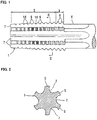
- Fig. 1 illustrates a cutting tap 1 according to the embodiment of the present invention.
- This cutting tap 1 is a nut tap used for manufacturing nuts in a tapping machine, and including a cutting portion 2 formed such that the outer diameter of the cutting portion 2 gradually decreases toward the axial front side of the cutting portion 2, a complete thread portion 3 formed such that the outer diameter of the complete thread portion 3 is uniform in the axial direction, and a columnar shank 4.
- the complete thread portion 3 is continuous with the axial rear side of the cutting portion 2.
- the shank 4 is continuous with the axial rear side of the complete thread portion 3.
- the cutting portion 2 is formed with a plurality of thread ridges 5 arranged at a constant pitch in the axial direction.
- the complete thread portion 3 is formed with a plurality of thread ridges 6 arranged at a constant pitch in the axial direction.
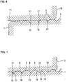
- the cutting tap 1 is formed in its outer periphery with a plurality of grooves 7 extending from the axial front end of the cutting tap 1 to the shank 4 through the cutting portion 2 and then the complete thread portion 3 so as to circumferentially divide a single thread into the thread ridges 5 of the cutting portion 2 and the thread ridges 6 of the complete thread portion 3.
- a cutting edge is constituted by the ridgeline at which the surface of each thread ridge 5 intersects with the inner surface of one of the grooves 7. As illustrated in Fig. 2 , the grooves 7 are circumferentially spaced apart from each other at regular intervals.
- the thread ridges 5 of the cutting portion 2 have an incomplete shape, that is, the crests of the thread ridges 5 are obliquely cut such that the major diameter of the thread ridges 5 gradually decreases toward the axial front side of the cutting portion 2.
- the effective diameter d 1 of the thread ridges 5 is uniform in the axial direction.
- the crests of the respective thread ridges 5 of the cutting portion 2 have major diameter reliefs such that the major diameter of the thread ridges 5 gradually decreases from the front side to the rear side of each thread ridge 5 in the rotation direction of the cutting tap 1. (In Fig.
- the cutting tap 1 rotates in the clockwise direction, so that the major diameter decreases in the counterclockwise direction at each thread ridge 5.
- the major diameter reliefs of the thread ridges 5 are set to be larger than the below-described effective diameter d 1 reliefs of the thread ridges 5.
- the effective diameter d 1 of the thread ridges 5 corresponds to the diameter of an imaginary cylinder (or cone) that passes through the portions of the thread ridges where their widths are equal to the widths of thread grooves formed between the respective axially adjacent pairs of thread ridges 5.
- the effective diameter d 1 of the thread ridges 5 is uniform in the axial direction
- the effective diameter d 1 thereof does not need to be uniform in a strict sense.
- the imaginary cylinder (or cone) having the effective diameter d 1 may be slightly tapered or inclined (by about 1/1000 to 3/1000) such that the effective diameter d 1 decreases from the axial front side of the cutting portion 2 toward the axial rear side thereof.
- the thread ridges 6 of the complete thread portion 3 have a complete shape, that is, the outer diameter of the complete thread portion 3 is uniform in the axial direction.
- the effective diameter of the thread ridges 6 of the complete thread portion 3 is uniform in the axial direction, and equal to the effective diameter d 1 of the thread ridges 5 of the cutting portion 2.
- the respective thread ridges 6 have major diameter reliefs (i.e., reliefs by which the major diameter of the thread ridges 6 gradually decrease from the front side toward the rear side of each thread ridge 6 in the rotation direction of the cutting tap 1) that are set at 0 (zero) or a minute value.
- the cutting portion 2 has a root 8 between each axially adjacent pair of the thread ridges 5.
- Each root 8 has a cross section extending straight in the axial direction, and both ends connected to respective flanks of the corresponding pair of the thread ridges 5.
- the complete thread portion 3 is also formed with a root 9 similar to the root 8, between each axially adjacent pair of the thread ridges 6.
- the root diameter d 2 of the cutting portion 2 is uniform in the axial direction.
- the root diameter of the complete thread portion 3 is uniform in the axial direction, and equal to the root diameter d 2 of the cutting portion 2.
- the thread ridges 5 of the cutting portion 2 and the thread ridges 6 of the complete thread portion 5 have effective diameter d 1 reliefs by which the effective diameter d 1 gradually decreases from the front side toward the rear side of each thread ridge in the rotation direction of the cutting tap 1, the effective diameter d 1 reliefs being set at 0 (zero) or a minute value.
- the reason why the effective diameter d 1 reliefs are set at 0 (zero) or a minute value is because if the effective diameter d 1 reliefs are set at a large value, when the cutting tap 1 is used to form an internal thread, the cutting tap 1 will not be able to be guided accurately, so that the thread ridges of the internal thread will be deformed (i.e., expanded).
- the roots 8, formed between the respective adjacent pairs of thread ridges 5 of the cutting portion 2, have root diameter d 2 reliefs by which the root diameter d 2 gradually decreases from the front side toward the rear side of each root 8 in the rotation direction of the cutting tap 1.
- the root diameter d 2 reliefs are set to be equal to the effective diameter d 1 reliefs of the thread ridges 5, namely, set at 0 (zero) or a minute value.
- the cutting portion 2 is formed with a plurality of deburring thread grooves 10 in some of the roots 8, formed between the respective axially adjacent pairs of thread ridges 5.
- the deburring thread grooves 10 are arranged at a constant pitch toward the axial front side of the cutting portion 2 from the rearmost ones of the roots 8 in which the deburring thread grooves 10 are formed.
- the pitch of the deburring thread grooves 10 is set such that each deburring thread groove 10 is located between the corresponding adjacent pair of the thread ridges 5, and does not necessarily need to be equal to the pitch of the thread ridges 5.
- the pitch of the deburring thread grooves 10 is set to be equal to the pitch of the thread ridges 5, because by setting in this way, the deburring thread grooves 10 can be reliably located between respective adjacent pairs of the thread ridges 5.
- the deburring thread grooves 10 are formed such that the groove bottom diameter d 3 of the deburring thread grooves 10 (which corresponds to the diameters of the deepest portions of the respective thread grooves 10 in the cross section along the center axis of the cutting tap 1) gradually decreases toward the axial front side of the cutting portion 2.
- Similar deburring thread grooves 10 are also formed at a constant pitch in the areas located axially forward of the frontmost thread ridges 5 at the axial front end of the cutting portion 2.
- the rearmost deburring thread grooves 10 at the axial rear end of the cutting portion 2 i.e., the deburring thread grooves 10 in which the groove bottom diameter d3 is the largest
- the rearmost deburring thread grooves 10 may be located in roots 9, i.e., the roots formed between respective adjacent pairs of the thread ridges 6.
- each deburring thread groove 10 comprises a V groove having a V-shaped cross section such that a step or steps are formed relative to the surface of the corresponding root 8.
- the deburring thread grooves 10 have groove bottom diameter d 3 reliefs by which the groove bottom diameter d 3 gradually decreases from the front side toward the rear side of each deburring thread groove 10 in the rotation direction of the cutting tap 1.
- the groove bottom diameter d 3 reliefs are set to be smaller than the major diameter reliefs of the thread ridges 5, and be larger than the effective diameter d 1 reliefs of the thread ridges 5.
- the groove bottom diameter d 3 reliefs may be set, for example, to be about 2/5 to 4/5 of the major diameter reliefs of the thread ridges 5.
- the above cutting tap 1 can be manufactured, for example, as follows: First, the grooves 7 are formed in the outer periphery of a tap blank having a round rod shape. Second, the thread ridges 5 of the cutting portion 2 and the thread ridges 6 of the complete thread portion 3 are formed by removing, from the outer periphery of the tap blank, portions corresponding to the thread grooves between respective axially adjacent pairs of the thread ridges 5, and portions corresponding to the thread grooves between respective axially adjacent pairs of the thread ridges 6. At this time, the thread ridges 5 and 6 are formed such that the effective diameter d 1 reliefs of the thread ridges 5 and 6 are set at 0 (zero) or a minute value.
- the crests of the respective thread ridges 5 of the cutting portion 2 are obliquely cut. At this time, these crests are cut such that the major diameter reliefs of the thread ridges 5 of the cutting portion 2 are larger than the effective diameter d 1 reliefs of the thread ridges 5.
- the deburring thread grooves 10 are formed in some of the roots 8, between respective adjacent pairs of the thread ridges 5, and in the areas located axially forward of the frontmost thread ridges 5 at the axial front end of the cutting portion 2. At this time, the deburring thread grooves 10 are formed such that the groove bottom diameter da reliefs of the thread grooves 10 are larger than the effective diameter d 1 reliefs of the thread ridges 5.
- the nut blank 12 is formed by forging or pressing, and formed in its center with the prepared hole 11.
- the prepared hole 11 comprises a through hole having a cylindrical inner peripheral surface. Though it is ideal that the inner diameter of the prepare hole 11 is uniform in the axial direction, it is difficult to make the inner diameter thereof uniform in a strict sense, because an error tends to occur when the nut blank 12 is manufactured.
- the inner diameter of the prepared hole 11 varies midway. Namely, a minute step 13 varies the inner diameter of the nut blank 12 by 0.1 mm or over (e.g. by about 0.2 mm) in diameter.
- the inner diameter of the prepared hole 11 is smaller over its entire area than the root diameter d 2 of the cutting tap 1.
- the thread ridges 5 of the cutting portion 2 engage with the prepared hole 11 for an internal thread, and cut/remove portions corresponding to the thread grooves of the internal thread, thereby forming surfaces corresponding to flanks 15 of thread ridges 14 of the internal thread.
- the deburring thread grooves 10 gradually deburr/cut the inner periphery of the prepared hole 11. The closer the deburring thread grooves 10 are located to the axial rear side of the cutting portion 2, the shallower/smaller the deburring thread grooves 10 are. As a result thereof, the closer the roots 8 are located to the axial rear side of the cutting portion 2, the deeper/larger the roots 8 are.
- surfaces corresponding to the crests 16 of the thread ridges 14 of the internal thread are formed by degrees.
- the major diameter reliefs of the crests of the thread ridges 5 and the groove bottom diameter d 3 reliefs of the deburring thread grooves 10 are larger than the effective diameter d 1 reliefs of the thread ridges 5, the rotational resistance of the cutting tap 1 is not made extremely large.
- spaces 17 are defined between the inner periphery of the prepared hole 11 and the respective inner surfaces of the deburring thread grooves 10. Therefore, due to cutting oil flowing into the spaces 17, it is possible to effectively reduce the rotational resistance of the cutting tap 1.
- the rearmost deburring thread grooves 10 at the axial rear end of the cutting portion 2 (strictly speaking, the roots 8 located axially rearward of the rearmost deburring thread grooves 10) pass the crests 16 of the thread ridges 14 of the internal thread, so that the crests 16 are completely formed.
- the rearmost thread ridges 5 at the axial rear end of the cutting portion 2 (strictly speaking, the thread ridges 6 having a complete shape and located axially rearward of the rearmost thread ridges 5) pass the flanks 15 of the thread ridges 14 of the internal thread, so that the flanks 15 are completely formed.
- This cutting tap 1 is configured such that when the cutting tap 1 is axially advanced while being rotated, the deburring thread grooves 10 deburr/cut the inner periphery of the prepared hole 11. Since the groove bottom diameter d 3 reliefs of the deburring thread grooves 10 are larger than the effective diameter d 1 reliefs of the thread ridges 5, the rotational resistance of the cutting tap 1 is not made extremely large. As a result thereof, the cutting tap 1 can cut the inner periphery of the prepared hole 11 with a relatively large cutting stock, and thus can form an internal thread with high accuracy even when the prepared hole 11 has an inner periphery of which the dimensional accuracy is low.
- this cutting tap 1 uses the deburring thread grooves 10, each of which comprises a V groove having a V-shaped cross section such that a step or steps are formed relative to the surface of the corresponding root 8, when the cutting tap 1 is manufactured, it is possible to separately form the deburring thread grooves 10, and the flanks of the thread ridges 5 on the outer periphery of the cutting tap 1. Therefore, it is possible to easily form the deburring thread grooves 10 such that the groove bottom diameter d 3 reliefs of the thread grooves 10 are made larger than the effective diameter d 1 reliefs of the thread ridges 5.
- FIGs. 9 and 10 illustrate the actual shape of the prepared hole 11 of the nut blank 12 used in this experiment, and the actual shape of the internal thread formed in this prepared hole 11 by the cutting tap 1.
- the inner diameter of the prepared hole 11 varies midway. Namely, the minute step 13 varies the inner diameter of the nut blank 12 by about 0.4 mm (in diameter).
- the pitch of the thread ridges 14 of the internal thread is 1.5mm. As can be seen from Figs.
- the cutting tap 1 of the above embodiment can cut the inner periphery of the prepared hole 11 with a relatively large cutting stock, specifically, 0.4 mm or over in diameter, and thus can form an internal thread with high accuracy even when the prepared hole 11 has an inner periphery of which the dimensional accuracy is low.
Landscapes
- Engineering & Computer Science (AREA)
- Mechanical Engineering (AREA)
- Forging (AREA)
- Cutting Tools, Boring Holders, And Turrets (AREA)
- Surgical Instruments (AREA)
- Milling Processes (AREA)
- Transmission Devices (AREA)
Claims (3)
- Gewindebohrer, der umfasst:eine Vielzahl von Gewinderippen (5), die in einem konstanten Abstand in einer axialen Richtung angeordnet und so ausgebildet sind, dass, wenn ein Flankendurchmesser (d1) der Gewinderippen (5) in der axialen Richtung einheitlich ist, ein Außendurchmesser der Gewinderippen (5) zu einer axialen Vorderseite des Gewindebohrers hin allmählich abnimmt; sowieGewindegründe (8), die zwischen den jeweiligen axial aneinandergrenzenden Paaren von Gewinderippen (5) ausgebildet sind,wobei die jeweiligen Gewinderippen (5) Rücknahmen des Flankendurchmessers (d1) aufweisen, durch die der Flankendurchmesser (d1) von einer vorderen Seite zu einer hinteren Seite jeder der Gewinderippen (5) in einer Drehrichtung des Gewindebohrers allmählich abnimmt, und die Rücknahmen des Flankendurchmessers (d1) auf 0 oder einen sehr geringen Wert eingestellt sind, unddie jeweiligen Gewindegründe (8) Rücknahmen des Kerndurchmessers (d2) aufweisen, durch die ein Kerndurchmesser (d2) der Gewindegründe (8) von einer vorderen Seite zu einer hinteren Seite jedes der Gewindegründe (8) in der Drehrichtung des Gewindebohrers allmählich abnimmt, und die Rücknahmen des Kerndurchmessers (d2) so eingestellt sind, dass sie den Rücknahmen des Flankendurchmessers (d1) gleich sind,dadurch gekennzeichnet, dass der Gewindebohrer des Weiteren eine Vielzahl von entgratenden Gewindegängen (10), umfasst, die in einigen oder allen der Gewindegründe (8) in einem konstanten Abstand von hintersten der einigen oder allen der Gewindegründe (8) auf die axiale Vorderseite des Gewindebohrers zu so ausgebildet sind, dass ein Gewindegang-Bodendurchmesser (d3) der entgratenden Gewindegänge (10) zu der axialen Vorderseite des Gewindebohrers hin allmählich abnimmt,wobei die jeweiligen entgratenden Gewindegänge (10) Rücknahmen des Gewindegang-Bodendurchmessers (d3) aufweisen, durch die der Gewindegang-Bodendurchmesser (d3) von einer vorderen Seite zu einer hinteren Seite jedes der entgratenden Gewindegänge (10) hin in der Drehrichtung des Gewindebohrers allmählich abnimmt, und die Rücknahmen des Gewindegang-Bodendurchmessers (d3) so eingestellt sind, dass sie größer sind als die Rücknahmen des Flankendurchmessers (d1) der Gewinderippen (5).
- Gewindebohrer nach Anspruch 1, wobei jeder der entgratenden Gewindegänge (10) eine V-Rille umfasst, die einen V-förmigen Querschnitt hat, und ein Absatz relativ zu einer Oberfläche des jeweiligen der Gewindegründe (8) ausgebildet ist.
- Gewindebohrer nach Anspruch 1 oder 2, wobei die entgratenden Gewindegänge (10) so angeordnet und geformt sind, dass die entgratenden Gewindegänge (10) umso tiefer relativ zu den Gewindegründen (8) sind, je näher die entgratenden Gewindegänge (10) an der axialen Vorderseite des Gewindebohrers liegen.
Applications Claiming Priority (2)
| Application Number | Priority Date | Filing Date | Title |
|---|---|---|---|
| JP2014182206A JP5788579B1 (ja) | 2014-09-08 | 2014-09-08 | 切削タップ |
| PCT/JP2015/058868 WO2016038912A1 (ja) | 2014-09-08 | 2015-03-24 | 切削タップ |
Publications (3)
| Publication Number | Publication Date |
|---|---|
| EP3192605A1 EP3192605A1 (de) | 2017-07-19 |
| EP3192605A4 EP3192605A4 (de) | 2017-10-04 |
| EP3192605B1 true EP3192605B1 (de) | 2018-10-10 |
Family
ID=54207209
Family Applications (1)
| Application Number | Title | Priority Date | Filing Date |
|---|---|---|---|
| EP15840509.2A Active EP3192605B1 (de) | 2014-09-08 | 2015-03-24 | Gewindebohrer |
Country Status (6)
| Country | Link |
|---|---|
| US (1) | US10406618B2 (de) |
| EP (1) | EP3192605B1 (de) |
| JP (1) | JP5788579B1 (de) |
| KR (1) | KR101804720B1 (de) |
| CN (1) | CN106660151B (de) |
| WO (1) | WO2016038912A1 (de) |
Families Citing this family (6)
| Publication number | Priority date | Publication date | Assignee | Title |
|---|---|---|---|---|
| BR112018011207B1 (pt) * | 2015-12-02 | 2022-12-06 | Osg Corporation | Torneira em espiral |
| JP7006276B2 (ja) * | 2016-01-13 | 2022-01-24 | 株式会社Moldino | ねじ切りカッター |
| KR101850300B1 (ko) | 2016-07-07 | 2018-04-19 | 안명구 | 나사 가공 툴 |
| CN109648022B (zh) * | 2019-02-02 | 2024-01-23 | 张咏 | 一种无缝无毛刺挤压丝锥及其制作的内螺纹 |
| KR102283980B1 (ko) | 2020-11-26 | 2021-08-02 | 조건 | 휴대형 전동 태핑 장치 |
| EP4112214A1 (de) * | 2021-06-30 | 2023-01-04 | Walter Ag | Gewindebohrer zum bearbeiten von metall |
Family Cites Families (22)
| Publication number | Priority date | Publication date | Assignee | Title |
|---|---|---|---|---|
| DE473066C (de) * | 1929-03-11 | Julius Hille | Gewindebohrer fuer Grobgewinde | |
| US3125772A (en) * | 1964-03-24 | cylindrical thread cutting tool having a chamfered | ||
| FR400566A (fr) * | 1909-03-10 | 1909-07-31 | Andre Arthur Joseph Minne | Système de tarauds et filières à denture rationnelle |
| US1725233A (en) * | 1926-12-22 | 1929-08-20 | John Bath | Tap for cutting square and acme threads |
| FR705837A (fr) * | 1930-11-17 | 1931-06-12 | Skf Svenska Kullagerfab Ab | Taraud |
| US1968103A (en) * | 1932-02-04 | 1934-07-31 | Dardelet Threadlock Corp | Tap |
| DE848899C (de) | 1950-08-08 | 1952-09-08 | Willi Mueller | Verfahren zur Herstellung konischer Gewinde, insbesondere fuer Gewindebohrer |
| GB1039564A (en) * | 1962-04-27 | 1966-08-17 | Balax Internat Ltd | Method of manufacture of thread-forming taps |
| US3355752A (en) * | 1965-08-04 | 1967-12-05 | Nautchno Izsledovatelski I Pk | Tapping tool |
| JPS57189735A (en) | 1981-05-14 | 1982-11-22 | Toyota Motor Corp | Apparatus for positioning work such as spline |
| JPS6015622Y2 (ja) * | 1981-05-27 | 1985-05-16 | オ−エスジ−株式会社 | 切削タツプ |
| JPH01148229A (ja) | 1987-12-04 | 1989-06-09 | Kao Corp | 清掃用拭き取りシート |
| JPH0388627A (ja) | 1989-08-30 | 1991-04-15 | Toshiba Corp | 給紙装置および画像形成装置 |
| JPH0388627U (de) * | 1989-12-27 | 1991-09-10 | ||
| JPH0976121A (ja) | 1995-09-11 | 1997-03-25 | Okuma Mach Works Ltd | ねじ立て用工具 |
| JP2010046758A (ja) * | 2008-08-21 | 2010-03-04 | Sakai Seiko Kk | タップ、およびめねじ加工方法 |
| JP2012061577A (ja) | 2010-09-17 | 2012-03-29 | Sakai Seiko Kk | 切削タップ |
| WO2013124981A1 (ja) * | 2012-02-22 | 2013-08-29 | 酒井精工株式会社 | 切削タップ |
| CN103506716A (zh) * | 2012-06-29 | 2014-01-15 | 江阴市强力化纤有限公司 | 设有排屑槽的跳牙丝锥 |
| CN202845970U (zh) * | 2012-09-27 | 2013-04-03 | 常州耐之力刀具制造有限公司 | 硬质合金丝锥 |
| US9481044B2 (en) * | 2013-05-07 | 2016-11-01 | Dc Swiss Sa | Method for obtaining a complete threading profile by milling and milling tool |
| CN203459782U (zh) * | 2013-09-10 | 2014-03-05 | 江苏华久特钢工具有限公司 | 改进型导向丝锥 |
-
2014
- 2014-09-08 JP JP2014182206A patent/JP5788579B1/ja active Active
-
2015
- 2015-03-24 US US15/313,720 patent/US10406618B2/en active Active
- 2015-03-24 CN CN201580027208.5A patent/CN106660151B/zh active Active
- 2015-03-24 WO PCT/JP2015/058868 patent/WO2016038912A1/ja not_active Ceased
- 2015-03-24 EP EP15840509.2A patent/EP3192605B1/de active Active
- 2015-03-24 KR KR1020167032536A patent/KR101804720B1/ko active Active
Also Published As
| Publication number | Publication date |
|---|---|
| EP3192605A4 (de) | 2017-10-04 |
| KR101804720B1 (ko) | 2017-12-04 |
| US10406618B2 (en) | 2019-09-10 |
| CN106660151A (zh) | 2017-05-10 |
| EP3192605A1 (de) | 2017-07-19 |
| JP5788579B1 (ja) | 2015-09-30 |
| JP2016055366A (ja) | 2016-04-21 |
| CN106660151B (zh) | 2018-12-14 |
| WO2016038912A1 (ja) | 2016-03-17 |
| KR20160146906A (ko) | 2016-12-21 |
| US20170189979A1 (en) | 2017-07-06 |
Similar Documents
| Publication | Publication Date | Title |
|---|---|---|
| US10406618B2 (en) | Cutting tap | |
| JP5651605B2 (ja) | チップブレーカパターンを有する回転式切削工具 | |
| JP6266603B2 (ja) | ワークピースにねじ山を形成する方法および工具 | |
| IL28549A (en) | Rotary threaded fastener and method of making same | |
| JP5701554B2 (ja) | 案内付きタップ | |
| US9844817B2 (en) | Replaceable cutting head having threaded mounting portion with two spaced apart conical abutment surfaces provided with the same cone angle, tool holder and rotary cutting tool | |
| TWI598169B (zh) | 用於形成一內螺紋的方法及由一本體及一螺紋切割器構成的組合 | |
| US20110200404A1 (en) | Spiral tap | |
| CN104114309A (zh) | 用于在工件上无屑制造或精加工螺纹的刀具,特别是冷成型丝锥或螺纹成型丝锥 | |
| CN109689261B (zh) | 螺纹形成刀具 | |
| JP5813226B2 (ja) | 盛上げタップ | |
| CN105209202B (zh) | 螺纹切削用丝锥 | |
| WO2019008865A1 (ja) | ネジ抜取工具 | |
| CN105290520B (zh) | 由毛坯制造齿轮的滚齿装置和方法 | |
| US20240375199A1 (en) | Thread cutting drill tool for metal cutting | |
| US9925607B2 (en) | Helical broach | |
| EP3473365B1 (de) | Gewindeformender bohrer und herstellungsverfahren für gewindeformenden bohrer | |
| JP2012061577A (ja) | 切削タップ | |
| US9757792B1 (en) | Method for making a die for roll forming a dual threaded bolt | |
| JP2017064905A (ja) | 溝形成工具 | |
| JP6368950B2 (ja) | ブローチ | |
| JP6581497B2 (ja) | 切削タップ | |
| WO2013124981A1 (ja) | 切削タップ | |
| JP7174686B2 (ja) | フレア状隆起部を有するネジ山成形具 | |
| JP3126900U (ja) | タッピンねじ |
Legal Events
| Date | Code | Title | Description |
|---|---|---|---|
| STAA | Information on the status of an ep patent application or granted ep patent |
Free format text: STATUS: THE INTERNATIONAL PUBLICATION HAS BEEN MADE |
|
| PUAI | Public reference made under article 153(3) epc to a published international application that has entered the european phase |
Free format text: ORIGINAL CODE: 0009012 |
|
| STAA | Information on the status of an ep patent application or granted ep patent |
Free format text: STATUS: REQUEST FOR EXAMINATION WAS MADE |
|
| 17P | Request for examination filed |
Effective date: 20161122 |
|
| AK | Designated contracting states |
Kind code of ref document: A1 Designated state(s): AL AT BE BG CH CY CZ DE DK EE ES FI FR GB GR HR HU IE IS IT LI LT LU LV MC MK MT NL NO PL PT RO RS SE SI SK SM TR |
|
| AX | Request for extension of the european patent |
Extension state: BA ME |
|
| A4 | Supplementary search report drawn up and despatched |
Effective date: 20170904 |
|
| RIC1 | Information provided on ipc code assigned before grant |
Ipc: B23G 5/06 20060101AFI20170829BHEP |
|
| DAV | Request for validation of the european patent (deleted) | ||
| DAX | Request for extension of the european patent (deleted) | ||
| GRAP | Despatch of communication of intention to grant a patent |
Free format text: ORIGINAL CODE: EPIDOSNIGR1 |
|
| STAA | Information on the status of an ep patent application or granted ep patent |
Free format text: STATUS: GRANT OF PATENT IS INTENDED |
|
| INTG | Intention to grant announced |
Effective date: 20180507 |
|
| GRAS | Grant fee paid |
Free format text: ORIGINAL CODE: EPIDOSNIGR3 |
|
| GRAA | (expected) grant |
Free format text: ORIGINAL CODE: 0009210 |
|
| STAA | Information on the status of an ep patent application or granted ep patent |
Free format text: STATUS: THE PATENT HAS BEEN GRANTED |
|
| AK | Designated contracting states |
Kind code of ref document: B1 Designated state(s): AL AT BE BG CH CY CZ DE DK EE ES FI FR GB GR HR HU IE IS IT LI LT LU LV MC MK MT NL NO PL PT RO RS SE SI SK SM TR |
|
| REG | Reference to a national code |
Ref country code: GB Ref legal event code: FG4D |
|
| REG | Reference to a national code |
Ref country code: CH Ref legal event code: EP Ref country code: AT Ref legal event code: REF Ref document number: 1050648 Country of ref document: AT Kind code of ref document: T Effective date: 20181015 |
|
| REG | Reference to a national code |
Ref country code: IE Ref legal event code: FG4D |
|
| REG | Reference to a national code |
Ref country code: DE Ref legal event code: R096 Ref document number: 602015018089 Country of ref document: DE |
|
| REG | Reference to a national code |
Ref country code: NL Ref legal event code: MP Effective date: 20181010 |
|
| REG | Reference to a national code |
Ref country code: LT Ref legal event code: MG4D |
|
| REG | Reference to a national code |
Ref country code: AT Ref legal event code: MK05 Ref document number: 1050648 Country of ref document: AT Kind code of ref document: T Effective date: 20181010 |
|
| PG25 | Lapsed in a contracting state [announced via postgrant information from national office to epo] |
Ref country code: NL Free format text: LAPSE BECAUSE OF FAILURE TO SUBMIT A TRANSLATION OF THE DESCRIPTION OR TO PAY THE FEE WITHIN THE PRESCRIBED TIME-LIMIT Effective date: 20181010 |
|
| PG25 | Lapsed in a contracting state [announced via postgrant information from national office to epo] |
Ref country code: IS Free format text: LAPSE BECAUSE OF FAILURE TO SUBMIT A TRANSLATION OF THE DESCRIPTION OR TO PAY THE FEE WITHIN THE PRESCRIBED TIME-LIMIT Effective date: 20190210 Ref country code: ES Free format text: LAPSE BECAUSE OF FAILURE TO SUBMIT A TRANSLATION OF THE DESCRIPTION OR TO PAY THE FEE WITHIN THE PRESCRIBED TIME-LIMIT Effective date: 20181010 Ref country code: BG Free format text: LAPSE BECAUSE OF FAILURE TO SUBMIT A TRANSLATION OF THE DESCRIPTION OR TO PAY THE FEE WITHIN THE PRESCRIBED TIME-LIMIT Effective date: 20190110 Ref country code: HR Free format text: LAPSE BECAUSE OF FAILURE TO SUBMIT A TRANSLATION OF THE DESCRIPTION OR TO PAY THE FEE WITHIN THE PRESCRIBED TIME-LIMIT Effective date: 20181010 Ref country code: PL Free format text: LAPSE BECAUSE OF FAILURE TO SUBMIT A TRANSLATION OF THE DESCRIPTION OR TO PAY THE FEE WITHIN THE PRESCRIBED TIME-LIMIT Effective date: 20181010 Ref country code: LT Free format text: LAPSE BECAUSE OF FAILURE TO SUBMIT A TRANSLATION OF THE DESCRIPTION OR TO PAY THE FEE WITHIN THE PRESCRIBED TIME-LIMIT Effective date: 20181010 Ref country code: LV Free format text: LAPSE BECAUSE OF FAILURE TO SUBMIT A TRANSLATION OF THE DESCRIPTION OR TO PAY THE FEE WITHIN THE PRESCRIBED TIME-LIMIT Effective date: 20181010 Ref country code: NO Free format text: LAPSE BECAUSE OF FAILURE TO SUBMIT A TRANSLATION OF THE DESCRIPTION OR TO PAY THE FEE WITHIN THE PRESCRIBED TIME-LIMIT Effective date: 20190110 Ref country code: FI Free format text: LAPSE BECAUSE OF FAILURE TO SUBMIT A TRANSLATION OF THE DESCRIPTION OR TO PAY THE FEE WITHIN THE PRESCRIBED TIME-LIMIT Effective date: 20181010 Ref country code: AT Free format text: LAPSE BECAUSE OF FAILURE TO SUBMIT A TRANSLATION OF THE DESCRIPTION OR TO PAY THE FEE WITHIN THE PRESCRIBED TIME-LIMIT Effective date: 20181010 |
|
| PG25 | Lapsed in a contracting state [announced via postgrant information from national office to epo] |
Ref country code: AL Free format text: LAPSE BECAUSE OF FAILURE TO SUBMIT A TRANSLATION OF THE DESCRIPTION OR TO PAY THE FEE WITHIN THE PRESCRIBED TIME-LIMIT Effective date: 20181010 Ref country code: PT Free format text: LAPSE BECAUSE OF FAILURE TO SUBMIT A TRANSLATION OF THE DESCRIPTION OR TO PAY THE FEE WITHIN THE PRESCRIBED TIME-LIMIT Effective date: 20190210 Ref country code: SE Free format text: LAPSE BECAUSE OF FAILURE TO SUBMIT A TRANSLATION OF THE DESCRIPTION OR TO PAY THE FEE WITHIN THE PRESCRIBED TIME-LIMIT Effective date: 20181010 Ref country code: RS Free format text: LAPSE BECAUSE OF FAILURE TO SUBMIT A TRANSLATION OF THE DESCRIPTION OR TO PAY THE FEE WITHIN THE PRESCRIBED TIME-LIMIT Effective date: 20181010 Ref country code: GR Free format text: LAPSE BECAUSE OF FAILURE TO SUBMIT A TRANSLATION OF THE DESCRIPTION OR TO PAY THE FEE WITHIN THE PRESCRIBED TIME-LIMIT Effective date: 20190111 |
|
| REG | Reference to a national code |
Ref country code: DE Ref legal event code: R097 Ref document number: 602015018089 Country of ref document: DE |
|
| PG25 | Lapsed in a contracting state [announced via postgrant information from national office to epo] |
Ref country code: CZ Free format text: LAPSE BECAUSE OF FAILURE TO SUBMIT A TRANSLATION OF THE DESCRIPTION OR TO PAY THE FEE WITHIN THE PRESCRIBED TIME-LIMIT Effective date: 20181010 Ref country code: DK Free format text: LAPSE BECAUSE OF FAILURE TO SUBMIT A TRANSLATION OF THE DESCRIPTION OR TO PAY THE FEE WITHIN THE PRESCRIBED TIME-LIMIT Effective date: 20181010 |
|
| PLBE | No opposition filed within time limit |
Free format text: ORIGINAL CODE: 0009261 |
|
| STAA | Information on the status of an ep patent application or granted ep patent |
Free format text: STATUS: NO OPPOSITION FILED WITHIN TIME LIMIT |
|
| PG25 | Lapsed in a contracting state [announced via postgrant information from national office to epo] |
Ref country code: SK Free format text: LAPSE BECAUSE OF FAILURE TO SUBMIT A TRANSLATION OF THE DESCRIPTION OR TO PAY THE FEE WITHIN THE PRESCRIBED TIME-LIMIT Effective date: 20181010 Ref country code: RO Free format text: LAPSE BECAUSE OF FAILURE TO SUBMIT A TRANSLATION OF THE DESCRIPTION OR TO PAY THE FEE WITHIN THE PRESCRIBED TIME-LIMIT Effective date: 20181010 Ref country code: EE Free format text: LAPSE BECAUSE OF FAILURE TO SUBMIT A TRANSLATION OF THE DESCRIPTION OR TO PAY THE FEE WITHIN THE PRESCRIBED TIME-LIMIT Effective date: 20181010 Ref country code: SM Free format text: LAPSE BECAUSE OF FAILURE TO SUBMIT A TRANSLATION OF THE DESCRIPTION OR TO PAY THE FEE WITHIN THE PRESCRIBED TIME-LIMIT Effective date: 20181010 |
|
| 26N | No opposition filed |
Effective date: 20190711 |
|
| PG25 | Lapsed in a contracting state [announced via postgrant information from national office to epo] |
Ref country code: SI Free format text: LAPSE BECAUSE OF FAILURE TO SUBMIT A TRANSLATION OF THE DESCRIPTION OR TO PAY THE FEE WITHIN THE PRESCRIBED TIME-LIMIT Effective date: 20181010 Ref country code: MC Free format text: LAPSE BECAUSE OF FAILURE TO SUBMIT A TRANSLATION OF THE DESCRIPTION OR TO PAY THE FEE WITHIN THE PRESCRIBED TIME-LIMIT Effective date: 20181010 |
|
| REG | Reference to a national code |
Ref country code: CH Ref legal event code: PL |
|
| GBPC | Gb: european patent ceased through non-payment of renewal fee |
Effective date: 20190324 |
|
| PG25 | Lapsed in a contracting state [announced via postgrant information from national office to epo] |
Ref country code: LU Free format text: LAPSE BECAUSE OF NON-PAYMENT OF DUE FEES Effective date: 20190324 |
|
| REG | Reference to a national code |
Ref country code: BE Ref legal event code: MM Effective date: 20190331 |
|
| PG25 | Lapsed in a contracting state [announced via postgrant information from national office to epo] |
Ref country code: CH Free format text: LAPSE BECAUSE OF NON-PAYMENT OF DUE FEES Effective date: 20190331 Ref country code: GB Free format text: LAPSE BECAUSE OF NON-PAYMENT OF DUE FEES Effective date: 20190324 Ref country code: IE Free format text: LAPSE BECAUSE OF NON-PAYMENT OF DUE FEES Effective date: 20190324 Ref country code: LI Free format text: LAPSE BECAUSE OF NON-PAYMENT OF DUE FEES Effective date: 20190331 |
|
| PG25 | Lapsed in a contracting state [announced via postgrant information from national office to epo] |
Ref country code: BE Free format text: LAPSE BECAUSE OF NON-PAYMENT OF DUE FEES Effective date: 20190331 |
|
| PG25 | Lapsed in a contracting state [announced via postgrant information from national office to epo] |
Ref country code: TR Free format text: LAPSE BECAUSE OF FAILURE TO SUBMIT A TRANSLATION OF THE DESCRIPTION OR TO PAY THE FEE WITHIN THE PRESCRIBED TIME-LIMIT Effective date: 20181010 |
|
| PG25 | Lapsed in a contracting state [announced via postgrant information from national office to epo] |
Ref country code: MT Free format text: LAPSE BECAUSE OF NON-PAYMENT OF DUE FEES Effective date: 20190324 |
|
| PG25 | Lapsed in a contracting state [announced via postgrant information from national office to epo] |
Ref country code: CY Free format text: LAPSE BECAUSE OF FAILURE TO SUBMIT A TRANSLATION OF THE DESCRIPTION OR TO PAY THE FEE WITHIN THE PRESCRIBED TIME-LIMIT Effective date: 20181010 |
|
| PG25 | Lapsed in a contracting state [announced via postgrant information from national office to epo] |
Ref country code: HU Free format text: LAPSE BECAUSE OF FAILURE TO SUBMIT A TRANSLATION OF THE DESCRIPTION OR TO PAY THE FEE WITHIN THE PRESCRIBED TIME-LIMIT; INVALID AB INITIO Effective date: 20150324 |
|
| PG25 | Lapsed in a contracting state [announced via postgrant information from national office to epo] |
Ref country code: MK Free format text: LAPSE BECAUSE OF FAILURE TO SUBMIT A TRANSLATION OF THE DESCRIPTION OR TO PAY THE FEE WITHIN THE PRESCRIBED TIME-LIMIT Effective date: 20181010 |
|
| PGFP | Annual fee paid to national office [announced via postgrant information from national office to epo] |
Ref country code: IT Payment date: 20250327 Year of fee payment: 11 |
|
| PGFP | Annual fee paid to national office [announced via postgrant information from national office to epo] |
Ref country code: DE Payment date: 20260326 Year of fee payment: 12 |
|
| PGFP | Annual fee paid to national office [announced via postgrant information from national office to epo] |
Ref country code: FR Payment date: 20260330 Year of fee payment: 12 |