EP3192602B1 - Verfahren zur verarbeitung eines zu verarbeitenden artikels - Google Patents
Verfahren zur verarbeitung eines zu verarbeitenden artikels Download PDFInfo
- Publication number
- EP3192602B1 EP3192602B1 EP15839545.9A EP15839545A EP3192602B1 EP 3192602 B1 EP3192602 B1 EP 3192602B1 EP 15839545 A EP15839545 A EP 15839545A EP 3192602 B1 EP3192602 B1 EP 3192602B1
- Authority
- EP
- European Patent Office
- Prior art keywords
- layer
- outer shell
- fresh air
- air inlet
- inner bag
- Prior art date
- Legal status (The legal status is an assumption and is not a legal conclusion. Google has not performed a legal analysis and makes no representation as to the accuracy of the status listed.)
- Active
Links
Images


Classifications
-
- B—PERFORMING OPERATIONS; TRANSPORTING
- B26—HAND CUTTING TOOLS; CUTTING; SEVERING
- B26F—PERFORATING; PUNCHING; CUTTING-OUT; STAMPING-OUT; SEVERING BY MEANS OTHER THAN CUTTING
- B26F1/00—Perforating; Punching; Cutting-out; Stamping-out; Apparatus therefor
- B26F1/16—Perforating by tool or tools of the drill type
-
- B—PERFORMING OPERATIONS; TRANSPORTING
- B23—MACHINE TOOLS; METAL-WORKING NOT OTHERWISE PROVIDED FOR
- B23B—TURNING; BORING
- B23B35/00—Methods for boring or drilling, or for working essentially requiring the use of boring or drilling machines; Use of auxiliary equipment in connection with such methods
-
- B—PERFORMING OPERATIONS; TRANSPORTING
- B23—MACHINE TOOLS; METAL-WORKING NOT OTHERWISE PROVIDED FOR
- B23B—TURNING; BORING
- B23B51/00—Tools for drilling machines
- B23B51/04—Drills for trepanning
-
- B—PERFORMING OPERATIONS; TRANSPORTING
- B65—CONVEYING; PACKING; STORING; HANDLING THIN OR FILAMENTARY MATERIAL
- B65D—CONTAINERS FOR STORAGE OR TRANSPORT OF ARTICLES OR MATERIALS, e.g. BAGS, BARRELS, BOTTLES, BOXES, CANS, CARTONS, CRATES, DRUMS, JARS, TANKS, HOPPERS, FORWARDING CONTAINERS; ACCESSORIES, CLOSURES, OR FITTINGS THEREFOR; PACKAGING ELEMENTS; PACKAGES
- B65D1/00—Rigid or semi-rigid containers having bodies formed in one piece, e.g. by casting metallic material, by moulding plastics, by blowing vitreous material, by throwing ceramic material, by moulding pulped fibrous material or by deep-drawing operations performed on sheet material
- B65D1/02—Bottles or similar containers with necks or like restricted apertures, designed for pouring contents
-
- B—PERFORMING OPERATIONS; TRANSPORTING
- B65—CONVEYING; PACKING; STORING; HANDLING THIN OR FILAMENTARY MATERIAL
- B65D—CONTAINERS FOR STORAGE OR TRANSPORT OF ARTICLES OR MATERIALS, e.g. BAGS, BARRELS, BOTTLES, BOXES, CANS, CARTONS, CRATES, DRUMS, JARS, TANKS, HOPPERS, FORWARDING CONTAINERS; ACCESSORIES, CLOSURES, OR FITTINGS THEREFOR; PACKAGING ELEMENTS; PACKAGES
- B65D23/00—Details of bottles or jars not otherwise provided for
- B65D23/02—Linings or internal coatings
-
- B—PERFORMING OPERATIONS; TRANSPORTING
- B65—CONVEYING; PACKING; STORING; HANDLING THIN OR FILAMENTARY MATERIAL
- B65D—CONTAINERS FOR STORAGE OR TRANSPORT OF ARTICLES OR MATERIALS, e.g. BAGS, BARRELS, BOTTLES, BOXES, CANS, CARTONS, CRATES, DRUMS, JARS, TANKS, HOPPERS, FORWARDING CONTAINERS; ACCESSORIES, CLOSURES, OR FITTINGS THEREFOR; PACKAGING ELEMENTS; PACKAGES
- B65D25/00—Details of other kinds or types of rigid or semi-rigid containers
- B65D25/14—Linings or internal coatings
- B65D25/16—Loose, or loosely-attached, linings
-
- B—PERFORMING OPERATIONS; TRANSPORTING
- B23—MACHINE TOOLS; METAL-WORKING NOT OTHERWISE PROVIDED FOR
- B23B—TURNING; BORING
- B23B2226/00—Materials of tools or workpieces not comprising a metal
- B23B2226/61—Plastics not otherwise provided for, e.g. nylon
-
- B—PERFORMING OPERATIONS; TRANSPORTING
- B23—MACHINE TOOLS; METAL-WORKING NOT OTHERWISE PROVIDED FOR
- B23B—TURNING; BORING
- B23B2251/00—Details of tools for drilling machines
- B23B2251/20—Number of cutting edges
- B23B2251/201—Single cutting edge
-
- B—PERFORMING OPERATIONS; TRANSPORTING
- B65—CONVEYING; PACKING; STORING; HANDLING THIN OR FILAMENTARY MATERIAL
- B65D—CONTAINERS FOR STORAGE OR TRANSPORT OF ARTICLES OR MATERIALS, e.g. BAGS, BARRELS, BOTTLES, BOXES, CANS, CARTONS, CRATES, DRUMS, JARS, TANKS, HOPPERS, FORWARDING CONTAINERS; ACCESSORIES, CLOSURES, OR FITTINGS THEREFOR; PACKAGING ELEMENTS; PACKAGES
- B65D2205/00—Venting means
-
- Y—GENERAL TAGGING OF NEW TECHNOLOGICAL DEVELOPMENTS; GENERAL TAGGING OF CROSS-SECTIONAL TECHNOLOGIES SPANNING OVER SEVERAL SECTIONS OF THE IPC; TECHNICAL SUBJECTS COVERED BY FORMER USPC CROSS-REFERENCE ART COLLECTIONS [XRACs] AND DIGESTS
- Y10—TECHNICAL SUBJECTS COVERED BY FORMER USPC
- Y10T—TECHNICAL SUBJECTS COVERED BY FORMER US CLASSIFICATION
- Y10T408/00—Cutting by use of rotating axially moving tool
- Y10T408/44—Cutting by use of rotating axially moving tool with means to apply transient, fluent medium to work or product
- Y10T408/45—Cutting by use of rotating axially moving tool with means to apply transient, fluent medium to work or product including Tool with duct
-
- Y—GENERAL TAGGING OF NEW TECHNOLOGICAL DEVELOPMENTS; GENERAL TAGGING OF CROSS-SECTIONAL TECHNOLOGIES SPANNING OVER SEVERAL SECTIONS OF THE IPC; TECHNICAL SUBJECTS COVERED BY FORMER USPC CROSS-REFERENCE ART COLLECTIONS [XRACs] AND DIGESTS
- Y10—TECHNICAL SUBJECTS COVERED BY FORMER USPC
- Y10T—TECHNICAL SUBJECTS COVERED BY FORMER US CLASSIFICATION
- Y10T408/00—Cutting by use of rotating axially moving tool
- Y10T408/89—Tool or Tool with support
- Y10T408/896—Having product-receiving chamber
Definitions
- the present invention relates to a method of machining a workpiece. This method is applied to a procedure of forming a fresh air inlet in an outer shell of a delaminatable container.
- delaminatable containers that inhibit entrance of air inside the container by an inner layer delaminated from an outer layer and shrunk with a decrease in the contents (e.g., JP 3455606 B ).
- Such delaminatable container is provided with an inner bag composed of an inner layer and an outer shell composed of an outer layer.
- the outer shell of the delaminatable container is provided with a fresh air inlet to enable shrinkage of the inner bag.
- the fresh air inlet is generally formed using a punch cutter or the like from outside the container where it is not easy to securely form a fresh air inlet in the outer shell without damaging the inner bag.
- JP 2008-156398 A discloses a core drill having a cutting part provided with an abrasive grain layer.
- JP 2003-340625 A discloses a drilling cutter having a cutting edge at the tip portion and being provided with a cut-out along an angle of slightly less than 180°.
- JP H08-175568 A describes a driller provided with a hemispherical front-end portion and a drills ending with a notch blade tip.
- JP H09-267207 A discloses a circular cutter not provided with a notch having a blade.
- EP 0 458 047 A1 discloses a boring drill provided with four small notches spaced apart by 90°, each having a blade part.
- the boring drill of US 5,681,134 A comprises a tubular end portion provided with a notch having two cutting edges spaced apart by more than 45°, preferably 100°.
- JP H08-175568 A particularly discloses a method of machining a workpiece, comprising: machining to form a round hole in a workpiece using a boring drill by pressing the boring tip against the workpiece while rotating the boring drill to contact the boring tip with the workpiece, wherein the workpiece is a delaminatable container including an outer shell and an inner bag, the inner bag delaminating from the outer shell to be shrunk along with a decrease in the contents, and the machining includes forming a fresh air inlet in the outer shell by pressing the boring tip against the outer shell to contact the boring tip with the outer shell.
- JP 3455606 B the fresh air inlet is formed in the mouth from the mouth outer surface side by, in a state of causing a bearer to abut on the mouth inner surface, bringing the cutter blade at the end of the punch cutter in proximity to the bearer. Then, by setting a gap between the bearer and the cutter blade not to be in a predetermined distance or less, it is prevented that the cutter blade damages the inner bag of the delaminatable container.
- JP 3455606 B has a problem that it is difficult to form a fresh air inlet in a portion other than the mouth of the container.
- the present invention has been made in view of such circumstances, and it is to provide a method of machining a workpiece that is capable of forming a fresh air inlet in an arbitrary position of the outer shell of the container.
- a method of machining a workpiece includes: machining to form a round hole in a workpiece using a boring drill by pressing the flat surface against the workpiece while rotating the drill to contact the blade with the workpiece, wherein the workpiece is a delaminatable container including an outer shell and an inner bag, the inner bag delaminating from the outer shell to be shrunk along with a decrease in the contents, and the machining includes forming a fresh air inlet in the outer shell by pressing the flat surface against the outer shell to contact the blade with the outer shell.
- the workpiece is machined using a boring drill having a tubular end portion having a flat surface and having a side surface vertical to the flat surface or a tapered side surface inclined to the center as coming closer to the flat surface.
- the boring drill further has a notch provided in the end portion in a range of 60 to 120 degrees along a circumference of the end portion, and a blade provided at a side of the notch.
- the outer shell of a general delaminatable container has certain stiffness and is readily elastically deformed.
- a round hole is thus readily formed by the method of the present invention.
- the inner bag is separated from the outer shell to be deformed towards the inside of the delaminatable container.
- the flat surface thus does not dig in the inner bag.
- the blade therefore, does not make contact with the inner bag not to damage the inner bag.
- a round hole is thus readily formed only in the outer shell of the delaminatable container.
- the round hole is applicable as a fresh air inlet to introduce fresh air between the outer shell and the inner bag.
- the end portion of the drill has a C-shaped cross section.
- the flat surface has a radial width from 0.1 to 0.2 mm.
- the end portion has an inner surface provided with a tapered surface widening towards an end.
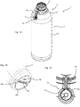
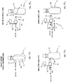
- a delaminatable container 1 in the first example is provided with a container body 3 and a valve member 5.
- the container body 3 is provided with a storage portion 7 to store the contents and a mouth 9 to deliver the contents from the storage portion 7.
- the container body 3 is provided with an outer layer 11 and an inner layer 13 in the storage portion 7 and the mouth 9.
- An outer shell 12 is composed of the outer layer 11 and an inner bag 14 is composed of the inner layer 13. Due to delamination of the inner layer 13 from the outer layer 11 with a decrease in the contents, the inner bag 14 delaminates from the outer shell 12 to be shrunk.
- the mouth 9 is equipped with external threads 9d.
- a cap, a pump, or the like having internal threads is mounted to the external threads 9d.
- Fig. 4 partially illustrates a cap 23 having an inner ring 25.
- the inner ring 25 has an outer diameter approximately same as an inner diameter of the mouth 9.
- An outer surface of the inner ring 25 abuts on an abutment surface 9a of the mouth 9, thereby preventing leakage of the contents.
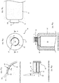
- the mouth 9 is equipped with an enlarged diameter portion 9b at the end.
- the enlarged diameter portion 9b has an inner diameter greater than the inner diameter in an abutment portion 9e, and thus the outer surface of the inner ring 25 does not make contact with the enlarged diameter portion 9b.
- the mouth 9 is also provided with an inner layer support portion 9c to inhibit slip down of the inner layer 13 in a position closer to the storage portion 7 than the abutment portion 9e.
- the inner layer support portion 9c is formed by providing a narrow part in the mouth 9. Even when the mouth 9 is equipped with the enlarged diameter portion 9b, the inner layer 13 sometimes delaminates from the outer layer 11 due to friction between the inner ring 25 and the inner layer 13. In the present example, even in such case, the inner layer support portion 9c inhibits slip down of the inner layer 13, and thus it is possible to inhibit falling out of the inner bag 14 in the outer shell 12.
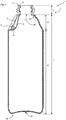
- the storage portion 7 is provided with a main portion 19 having an approximately constant cross-sectional shape in longitudinal directions of the storage portion and a shoulder portion 17 linking the main portion 19 to the mouth 9.
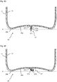
- the shoulder portion 17 is equipped with a bent portion 22.
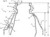
- the bent portion 22 is an area with a bending angle ⁇ illustrated in Fig. 3 of 140 degrees or less and having a radius of curvature on a container inner surface side of 4 mm or less. Without the bent portion 22, the delamination between the inner layer 13 and the outer layer 11 sometimes extends from the main portion 19 to the mouth 9 to delaminate the inner layer 13 from the outer layer 11 even in the mouth 9.
- the delamination of the inner layer 13 from the outer layer 11 in the mouth 9 is, however, undesirable because the delamination of the inner layer 13 from the outer layer 11 in the mouth 9 causes falling out of the inner bag 14 in the outer shell 12.
- the bent portion 22 is provided in the present example, even when delamination between the inner layer 13 and the outer layer 11 extends from the main portion 19 to the bent portion 22, the inner layer 13 is bent at the bent portion 22 as illustrated in Fig. 5 and the force to delaminate the inner layer 13 from the outer layer 11 is not transmitted to the area above the bent portion 22. As a result, the delamination between the inner layer 13 and the outer layer 11 in the area above the bent portion 22 is inhibited.
- the bent portion 22 is provided in the shoulder portion 17, the bent portion 22 may be provided at the boundary between the shoulder portion 17 and the main portion 19.
- the lower limit of bending angle ⁇ is not particularly defined, it is preferably 90 degrees or more for ease of manufacture.
- the lower limit of the radius of curvature is not particularly defined, it is preferably 0.2 mm or more for ease of manufacture.
- the bending angle ⁇ is preferably 120 degrees or less and the radius of curvature is preferably 2 mm or less.
- the bending angle ⁇ is, for example, 90, 95, 100, 105, 110, 115, 120, 125, 130, 135, and 140 degrees or it may be in a range between any two values exemplified here.
- the radius of curvature is, for example, 0.2, 0.4, 0.6, 0.8, 1, 1.2, 1.4, 1.6, 1.8, and 2 mm or it may be in a range between any two values exemplified here.
- the bent portion 22 is provided in a position where a distance L2 from a container center axis C to the container inner surface in the bent portion 22 is 1.3 times or more of a distance L1 from the container center axis C to the container inner surface in the mouth 9.
- the delaminatable container 1 in the present example is formed by blow molding.
- the larger L2/L1 causes a larger blow ratio in the bent portion 22, which results in a thinner thickness.
- L2/L1 ⁇ 1.3 the thickness of the inner layer 13 in the bent portion 22 thus becomes sufficiently thin and the inner layer 13 is easily bent at the bent portion 22 to more securely inhibit delamination of the inner layer 13 from the outer layer 11 in the mouth 9.
- L2/L1 is, for example, from 1.3 to 3 and preferably from 1.4 to 2. Specifically, L2/L1 is, for example, 1.3, 1.4, 1.5, 1.6, 1.7, 1.8, 1.9, 2, 2.5, and 3 or it may be in a range between any two values exemplified here.
- the thickness in the mouth 9 is from 0.45 to 0.50 mm
- the thickness in the bent portion 22 is from 0.25 to 0.30 mm
- the thickness of the main portion 19 is from 0.15 to 0.20 mm.
- the thickness in the bent portion 22 is thus sufficiently less than the thickness in the mouth 9, thereby effectively exhibiting functions of the bent portion 22.
- the storage portion 7 is equipped with the valve member 5 to regulate entrance and exit of air between an external space S of the container body 3 and an intermediate space 21 between the outer shell 12 and the inner bag 14.
- the outer shell 12 is equipped with a fresh air inlet 15 communicating with the intermediate space 21 and the external space S in the storage portion 7.
- the fresh air inlet 15 is a through hole provided only in the outer shell 12 and does not reach the inner bag 14.
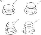
- the valve member 5 is provided with an axis 5a inserted into the fresh air inlet 15 and capable of sliding movement relative to the fresh air inlet 15, a lid 5c provided on the intermediate space 21 side of the axis 5a and having a cross-sectional area greater than that of the axis 5a, and a locking portion 5b provided on the external space S side of the axis 5a and preventing entrance of the valve member 5 to the intermediate space 21.
- the lid 5c is configured to substantially close the fresh air inlet 15 when the outer shell 12 is compressed and shaped to have a smaller cross-sectional area as coming closer to the axis 5a.
- the locking portion 5b is configured to be capable of introducing air in the intermediate space 21 when the outer shell 12 is restored after compression. When the outer shell 12 is compressed, the pressure in the intermediate space 21 becomes higher than external pressure and the air in the intermediate space 21 leaks outside from the fresh air inlet 15. The pressure difference and the air flow cause the lid 5c to move toward the fresh air inlet 15 to close the fresh air inlet 15 by the lid 5c. Since the lid 5c has a shape with a smaller cross-sectional area as coming closer to the axis 5a, the lid 5c readily fits into the fresh air inlet 15 to close the fresh air inlet 15.
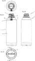
- Fig. 8 illustrates specific examples of the structure of the valve member 5.
- the valve member 5 is mounted to the container body 3 by inserting the lid 5c into the intermediate space 21 while the lid 5c presses and expands the fresh air inlet 15.
- the lid 5c therefore, preferably has an end in a tapered shape. Since such valve member 5 can be mounted only by pressing the lid 5c from outside the container body 3 into the intermediate space 21, it is excellent in productivity.
- the storage portion 7 is covered with a shrink film.
- the valve member 5 is mounted to a valve member mounting recess 7a provided in the storage portion 7.
- an air circulation groove 7b extending from the valve member mounting recess 7a in the direction of the mouth 9 is provided.
- the valve member mounting recess 7a is provided in the shoulder portion 17 of the outer shell 12.
- the shoulder portion 17 is an inclined surface, and a flat region FR is provided in the valve member mounting recess 7a. Since the flat region FR is provided approximately in parallel with the inclined surface of the shoulder portion 17, the flat region FR is also an inclined surface. Since the fresh air inlet 15 is provided in the flat region FR in the valve member mounting recess 7a, the fresh air inlet 15 is provided in the inclined surface. When the fresh air inlet 15 is provided in, for example, a vertical surface of the main portion 19, there is a risk that the once delaminated inner bag 14 makes contact with the valve member 5 to interfere with movement of the valve member 5.
- an inclination angle of the inclined surface is preferably from 45 to 89 degrees, more preferably from 55 to 85 degrees, and even more preferably from 60 to 80 degrees.
- the flat region FR in the valve member mounting recess 7a is provided across a width W of 3 mm or more (preferably 3.5 mm, 4 mm, or more) surrounding the fresh air inlet 15.
- the valve member mounting recess 7a is designed to be ⁇ 10 mm or more.
- the width W of the flat region FR is preferably not too large because a larger width W of the flat region FR causes the valve member mounting recess 7a to have a greater area, and as a result, the area of the gap between the outer shell 12 and the shrink film.
- the upper limit is, for example, 10 mm.
- the width W is, for example, from 3 to 10 mm. Specifically, it is, for example, 3, 3.5, 4, 4.5, 5, 6, 7, 8, 9, and 10 mm or it may be in a range between any two values exemplified here.
- a wider flat region FR on an outer surface side of the outer shell 12 causes a larger radius of curvature on an inner surface of the outer shell 12, and when the flat region FR is provided across the range of 3 mm or more surrounding the fresh air inlet 15 on the outer surface side of the outer shell, the radius of curvature on the inner surface of the outer shell 12 is sufficiently large, and as a result, the close adherence between the outer shell 12 and the valve member 5 is improved.
- the radius of curvature on the inner surface of the outer shell 12 is preferably 200 mm or more in a range of 2 mm surrounding the fresh air inlet 15 and even more preferably 250 mm or more or 300 mm or more. This is because, when the radius of curvature has such value, the inner surface of the outer shell 12 substantially becomes flat and the close adherence between the outer shell 12 and the valve member 5 is good.
- the storage portion 7 has a bottom surface 29 equipped with a central concave region 29a and a peripheral region 29b surrounding the former region, and the central concave region 29a is provided with a bottom seal protrusion 27 protruding from the bottom surface 29.
- the bottom seal protrusion 27 is a sealing portion of a laminated parison in blow molding using a tubular laminated parison provided with the outer layer 11 and the inner layer 13.
- the bottom seal protrusion 27 is provided with, in order from the bottom surface 29 side, a base portion 27d, a thinner portion 27a, and a thicker portion 27b having a thickness greater than that of the thinner portion 27a.
- the bottom seal protrusion 27 is in a state of standing approximately vertically to a plane P defined by the peripheral region 29b. In this state, however, when impact is applied to the container, the inner layers 13 in a welded portion 27c are prone to be separated from each other and the impact resistance is insufficient.
- the thinner portion 27a is softened by blowing hot air on the bottom seal protrusion 27 after blow molding to bend the bottom seal protrusion 27, as illustrated in Fig. 6B , in the thinner portion 27a.
- the impact resistance of the bottom seal protrusion 27 is thus improved simply by a simple procedure of bending the bottom seal protrusion 27.
- Fig. 6A the thinner portion 27a is softened by blowing hot air on the bottom seal protrusion 27 after blow molding to bend the bottom seal protrusion 27, as illustrated in Fig. 6B , in the thinner portion 27a.
- the bottom seal protrusion 27 does not protrude from the plane P defined by the peripheral region 29b in a state of being bent. This prevents, when the delaminatable container 1 is stood, instability of the delaminatable container 1 due to the bottom seal protrusion 27 sticking out of the plane P.
- the base portion 27d is provided on the bottom surface 29 side closer than the thinner portion 27a and is an area thicker than the thinner portion 27a. Although the base portion 27d does not have to be provided, the impact resistance of the bottom seal protrusion 27 is further improved by providing the thinner portion 27a on the base portion 27d.
- the concave region in the bottom surface 29 is provided across the entire bottom surface 29 in longitudinal directions of the bottom seal protrusion 27. That is, the central concave region 29a and the peripheral concave region 29c are connected. Such structure facilitates bending of the bottom seal protrusion 27.
- the layer structure of the container body 3 is described below in further detail.
- the container body 3 is provided with the outer layer 11 and the inner layer 13.
- the outer layer 11 is formed with a larger thickness than the inner layer 13 so as to increase the restorability thereof.
- the outer layer 11 is formed of, for example, low-density polyethylene, linear low-density polyethylene, high-density polyethylene, polypropylene, ethylene-propylene copolymer, or a mixture thereof, or the like.
- the outer layer 11 consists of a single layer or multiple layers, and at least one of the innermost and outermost layers thereof contains a lubricant. If the outer layer 11 consists of a single layer, that single layer serves as both innermost and outermost layers. Accordingly, that layer only has to contain a lubricant. If the outer layer 11 consists of two layers, the layer closer to the inside of the container serves as the innermost layer, and the layer closer to the outside of the container serves as the outermost layer.
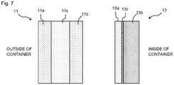
- the outer layer 11 consists of three layers, the layer closest to the inside of the container serves as the innermost layer, and the layer closest to the outside of the container serves as the outermost layer. As shown in Fig. 7 , the outer layer 11 preferably includes a repro layer 11c between an innermost layer 11b and an outermost layer 11a. As used herein, the term "repro layer” refers to a layer formed by recycling burrs generated when a container is molded. Further, if the outer layer 11 consists of multiple layers, both the innermost and outermost layers preferably contain a lubricant.
- the lubricant may be any type of commercially available common lubricant.
- the lubricant may be one of a hydrocarbon-based lubricant, a fatty acid-based lubricant, an aliphatic amide-based lubricant, a metal soap-based lubricant, and a combination of two or more thereof.
- the hydrocarbon-based lubricant include liquid paraffin, paraffin wax, and synthesized polyethylene wax.
- the fatty acid-based lubricant include stearic acid and stearyl alcohol.
- aliphatic amide-based lubricant examples include fatty amides, such as stearamide, oleic amide, and erucic acid amide, and alkylene fatty amides, such as methylene bis(stearamide) and ethylene bis(stearamide).
- the innermost layer of the outer layer 11 is a layer that makes contact with the inner layer 13.
- the outermost layer of the outer layer 11 is a layer that makes contact with a die during blow molding.
- One or both of the innermost layer and the outermost layer of the outer layer 11 may be formed with a random copolymer of propylene and another monomer. This enables improvement in shape restorability, transparency, and heat resistance of the outer shell 12.
- the random copolymer has a content of a monomer other than propylene of less than 50 mol% and preferably from 5 to 35 mol%. Specifically, this content is, for example, 5, 10, 15, 20, 25, and 30 mol% or it may be in a range between any two values exemplified here.
- the monomer to be copolymerized with propylene may be one that improves impact resistance of the random copolymer compared with a homopolymer of polypropylene, and ethylene is particularly preferred. In the case of a random copolymer of propylene and ethylene, the ethylene content is preferably from 5 to 30 mol%.
- the random copolymer preferably has a weight average molecular weight from 100 thousands to 500 thousands, and even more preferably from 100 thousands to 300 thousands.
- the weight average molecular weight is, for example, 100 thousands, 150 thousands, 200 thousands, 250 thousands, 300 thousands, 350 thousands, 400 thousands, 450 thousands, and 500 thousands or it may be in a range between any two values exemplified here.
- the random copolymer has a tensile modulus of elasticity preferably from 400 to 1600 MPa and more preferably from 1000 to 1600 MPa. This is because the shape restorability is particularly good with a tensile modulus of elasticity in such range.
- the tensile modulus of elasticity is, for example, 400, 500, 600, 700, 800, 900, 1000, 1100, 1200, 1300, 1400, 1500, and 1600 Mpa or it may be in a range between any two values exemplified here.
- a mixture obtained by mixing a flexible material, such as linear low density polyethylene, with the random copolymer may be used.
- the material to be mixed with the random copolymer is preferably mixed to be less than 50 weight% based on the entire mixture.
- a mixture obtained by mixing the random copolymer and linear low-density polyethylene at a weight ratio of 85:15 may be used.
- the inner layer 13 includes an EVOH layer 13a provided on a container outer surface side, an inner surface layer 13b provided on a container inner surface side of the EVOH layer 13a, and an adhesion layer 13c provided between the EVOH layer 13a and the inner surface layer 13b.
- the EVOH layer 13a is a layer containing an ethylene-vinyl alcohol copolymer (EVOH) resin and is obtained by hydrolysis of a copolymer of ethylene and vinyl acetate.
- the EVOH resin has an ethylene content, for example, from 25 to 50 mol%, and from the perspective of oxygen barrier properties, it is preferably 32 mol% or less.
- the lower limit of the ethylene content is preferably 25 mol% or more because the flexibility of the EVOH layer 13a is prone to decrease when the ethylene content is less.
- the EVOH layer 13a preferably contains an oxygen absorbent. The content of an oxygen absorbent in the EVOH layer 13a further improves the oxygen barrier properties of the EVOH layer 13a.
- the EVOH resin preferably has a melting point higher than the melting point of the resin contained in the outer layer 11.
- the inlet is prevented from reaching the inner layer 13 by the EVOH resin having a melting point higher than the melting point of the resin contained in the outer layer 11.
- a greater difference of (Melting Point of EVOH) - (Melting Point of the Resin from which the outer layer 11 is formed) is desired, and it is preferably 15°C or more and particularly preferably 30°C or more.
- the difference in melting points is, for example, from 5 to 50°C. Specifically, it is, for example, 5, 10, 15, 20, 25, 30, 35, 40, 45, and 50°C or it may be in a range between any two values exemplified here.
- the inner surface layer 13b is a layer to make contact with the contents of the delaminatable container 1. It contains, for example, polyolefin, such as low density polyethylene, linear low density polyethylene, high density polyethylene, polypropylene, an ethylene-propylene copolymer, and a mixture thereof, and preferably low density polyethylene or linear low density polyethylene.
- the resin contained in the inner surface layer 13b preferably has a tensile modulus of elasticity from 50 to 300 MPa and more preferably from 70 to 200 MPa. This is because the inner surface layer 13b is particularly flexible when the tensile modulus of elasticity is in such range. Specifically, the tensile modulus of elasticity is, for example, specifically for example, 50, 100, 150, 200, 250, and 300 Mpa or it may be in a range between any two values exemplified here.
- the adhesion layer 13c is a layer having a function of adhering the EVOH layer 13a to the inner surface layer 13b, and it is, for example, a product of adding acid modified polyolefin (e.g., maleic anhydride modified polyethylene) with carboxyl groups introduced therein to polyolefin described above or an ethylene-vinyl acetate copolymer (EVA).
- acid modified polyolefin e.g., maleic anhydride modified polyethylene
- EVA ethylene-vinyl acetate copolymer
- An example of the adhesion layer 13c is a mixture of acid modified polyethylene with low density polyethylene or linear low density polyethylene.
- a laminated parison in a melted state with a laminated structure e.g., a laminated structure of PE layer / adhesion layer / EVOH layer / PP layer / repro layer / PP layer in order from the container inner surface side
- a laminated structure e.g., a laminated structure of PE layer / adhesion layer / EVOH layer / PP layer / repro layer / PP layer in order from the container inner surface side
- a blowing nozzle is inserted into an opening of the mouth 9 of the container body 3 to blow air into a cavity of the split die in the mold closing state.
- the split die is opened to take out a blow molded article.
- the split die has a cavity shape to form various shapes of the container body 3, such as the valve member mounting recess 7a, the air circulation groove 7b, and the bottom seal protrusion 27, in the blow molded article.
- the split die is provided with a pinch-off below the bottom seal protrusion 27. Lower burrs are thus formed in the area below the bottom seal protrusion 27 and they are removed.
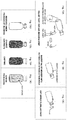
- a perforator 2 is used to form the fresh air inlet 15 in the outer shell 12 of the delaminatable container 1. This procedure is described in detail below.
- the delaminatable container 1 is set in a position close to the perforator 2.
- the perforator 2 is provided with a boring drill 30, having a body portion 31 and an end portion 32, and a motor 2c to rotationally drive the drill 30 through a transmission belt 2b.
- the perforator 2 is supported by a servo cylinder (not shown) to single-axis move the perforator 2 by rotation of a servo motor and is configured movably in an arrow X1 direction in Fig. 10A and in an arrow X2 direction in Fig. 10C .
- Such configuration enables rotation of the drill 30 while pressing the end portion 32 against the outer shell 12 of the delaminatable container 1.
- the control of the position and the moving speed of the perforator 2 by the servo motor enables reduction in tact time.
- the drill 30 is provided with a hollow 33 extending from the body portion 31 to the end portion 32 (see, Figs. 11A to 12B ) and is coupled to a ventilation pipe 2e in communication with the hollow 33.
- the ventilation pipe 2e is coupled to an air intake and exhaust system, not shown. This enables air suction from inside the drill 30 and air blowing inside the drill 30.
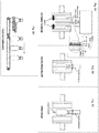
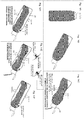
- the end portion 32 of the drill 30 is tubular having a C-shaped cross section.
- the end portion 32 is provided with a flat surface 34 and a notch 37, and the notch 37 has a side of a blade 38.
- the end portion 32 has a side 32a that may be, as illustrated in Figs. 11A-11E , vertical to the flat surface 34 or may be, as illustrated in Figs. 12A, 12B , a tapered surface inclined to the center as coming closer to the flat surface 34.
- the formed fresh air inlet 15 has an edge of a tapered surface widening towards outside and thus has an advantage of facilitating insertion of the valve member 5.
- the flat surface 34 has a radial width W preferably from 0.1 to 0.2 mm and more preferably from 0.12 to 0.18 mm.
- a too small width W causes easy damage of the inner bag 14 during perforation.
- a too large width W causes difficulty in contacting the blade 38 with the outer shell 12, making it difficult to perform smooth perforation.
- the notch 37 is provided in a range from 60 to 120 degrees and preferably from 75 to 105 degrees. The notch being provided in a too large range causes easy damage of the inner bag 14 during perforation, whereas the notch being provided in a too small range causes difficulty in smooth perforation.
- the blade 38 has an inclined plane P2 at an angle ⁇ to a circumscribed surface P1 preferably from 30 to 65 degrees and more preferably from 40 to 55 degrees. A too small angle ⁇ causes easy damage of the inner bag 14 during perforation, whereas a too large angle ⁇ causes difficulty in smooth perforation.
- the end portion 32 has an inner surface 35 provided with a tapered surface 36 widening towards the end. This facilitates movement of a cut piece 15a (see, Fig. 10C ) produced by perforation to the inner surface 35 side, not remaining on the delaminatable container 1 side.
- the tapered surface 36 has an angle to the flat surface 34 preferably from 95 to 110 degrees and more preferably from 95 to 105 degrees. In other words, as illustrated in Fig. 11E , the tapered surface 36 has an angle ⁇ in a direction X parallel to the rotation axis of the drill 30 preferably from 5 to 20 degrees and more preferably from 5 to 15 degrees.
- the inner surface 35 is preferably provided with an approximately annular groove 39 in a concave or V shape with a depth from 0.05 to 0.1 mm and a width from 0.1 to 0.2 mm with a pitch from 0.2 to 1 mm in a direction vertical to the flat surface 34 (direction X parallel to the rotation axis of the drill 30), and in this case, the cut piece 15a more readily moves to the inner surface 35.
- the pitch of the groove 39 is more preferably from 0.3 to 0.7 mm.
- the inner surface 35 is preferably subjected to blasting for even easier movement of the cut piece 15a to the inner surface 35.
- the inner bag 14 is delaminated from the outer shell 12 to be readily deformed towards inside the delaminatable container 1.
- the flat surface 34 thus does not dig in the inner bag 14 and the inner bag 14 does not make contact with the blade 38 to inhibit damaging of the inner bag 14.
- the drill 30 is used without heating. This gives an advantage of not melting the edge of the fresh air inlet 15 to form the edge sharply.
- the drill 30 is preferably form with a material having a high thermal conductivity (e.g., 35 W/(m•°C) or higher at 20°C).
- the drill 30 may be heated.
- the resin contained in the outermost layer of the inner bag 14 preferably has a melting point higher than the melting point of the resin contained in the innermost layer of the outer shell 12.
- the perforator 2 is set back in the arrow X2 direction to blow air into the hollow 33 of the drill 30, thereby emitting the cut piece 15a from the edge of the drill 30.
- preliminary delamination of the inner bag 14 is readily controlled.
- the preliminary delamination may be applied to the entire storage portion 7 or may be applied to part of the storage portion 7, it is preferred that preliminary delamination of the inner bag 14 from the outer shell 12 in approximately the entire storage portion 7 because it is not possible to check the presence of a pinhole in the inner bag 14 in a portion not subjected to preliminary delamination.
- the thinner portion 27a is softened by exposing the bottom seal protrusion 27 to hot air to bend the bottom seal protrusion 27.
- valve member 5 is inserted into the fresh air inlet 15.
- the inner bag 14 is expanded by blowing air into the inner bag 14.
- the inner bag 14 is filled with the contents.
- the storage portion 7 is covered with a shrink film to complete the product.
- the hot air bending procedure may be before the fresh air inlet opening procedure or may be before the inner layer preliminary delamination procedure.
- the procedure of cutting the upper tubular portion 41 may be before inserting the valve member 5 into the fresh air inlet 15.
- a side of the outer shell 12 is squeezed for compression to deliver the contents.
- the compressive force applied to the outer shell 12 directly becomes a compressive force to the inner bag 14 and the inner bag 14 is compressed to deliver the contents.
- the cap 23 has a built-in check valve, not shown, so that it is capable of delivering the contents in the inner bag 14 but not capable of taking fresh air in the inner bag 14. Therefore, when the compressive force applied to the outer shell 12 is removed after delivery of the contents, the outer shell 12 attempts to be back in the original shape by the restoring force of itself but the inner bag 14 remains deflated and only the outer shell 12 expands. Then, as illustrated in Fig. 14D , inside the intermediate space 21 between the inner bag 14 and the outer shell 12 is in a reduced pressure state to introduce fresh air in the intermediate space 21 through the fresh air inlet 15 formed in the outer shell 12.
- the lid 5c When the intermediate space 21 is in a reduced pressure state, the lid 5c is not pressed against the fresh air inlet 15 and thus it does not interfere with introduction of fresh air. Not to cause the locking portion 5b to interfere with introduction of fresh air even in a state where the locking portion 5b makes contact with the outer shell 12, the locking portion 5b is provided with an air passage securing mechanism, such as the projections 5d and grooves.
Landscapes
- Engineering & Computer Science (AREA)
- Mechanical Engineering (AREA)
- Life Sciences & Earth Sciences (AREA)
- Forests & Forestry (AREA)
- Ceramic Engineering (AREA)
- Packages (AREA)
- Containers Having Bodies Formed In One Piece (AREA)
- Drilling And Boring (AREA)
- Drilling Tools (AREA)
- Perforating, Stamping-Out Or Severing By Means Other Than Cutting (AREA)
Claims (4)
- Verfahren zur maschinellen Bearbeitung eines Werkstücks, umfassend:maschinelles Bearbeiten zum Ausbilden eines runden Lochs in einem Werkstück unter Verwendung eines Bohrers (30) durch Drücken einer ebenen Fläche (34) des Bohrers gegen das Werkstück, während der Bohrer (30) dreht, um eine Schneide (38) des Bohrers mit dem Werkstück in Kontakt zu bringen, wobeidas Werkstück ein delaminierbarer Behälter (1) ist, der eine Außenhülle (12) und einen inneren Beutel (14) umfasst, wobei der innere Beutel (14) sich im Zuge einer Abnahme des Inhalts von der Außenhülle (12) ablöst und schrumpft, unddas maschinelle Bearbeiten ein Ausbilden eines Frischlufteinlasses (15) in der Außenhülle (12) durch Drücken der ebenen Fläche (34) gegen die Außenhülle (12), um die Schneide (38) mit der Außenhülle (12) in Kontakt zu bringen, umfasst, wobeider Bohrer (30) Folgendes umfasst:einen rohrförmigen Endabschnitt (32), der die ebene Fläche (34) und eine Seitenfläche (32a), die senkrecht zu der ebenen Fläche (34) ist, oder eine konische Seitenfläche (32a), die der ebenen Fläche (34) näherkommend zur Mitte geneigt ist, aufweist;eine Kerbe (37), die in dem Endabschnitt (32) vorgesehen ist; undwobei die Schneide (38) an einer Seite der Kerbe (37) vorgesehen ist,wobei die Kerbe (37) in einem Bereich von 60 bis 120 Grad entlang eines Umfangs des Endabschnitts (32) vorgesehen ist.
- Verfahren nach Anspruch 1, wobei der Endabschnitt (32) des Bohrers (30) einen C-förmigen Querschnitt aufweist.
- Verfahren nach einem der Ansprüche 1 oder 2, wobei die ebene Fläche (34) eine radiale Breite (W) von 0,1 bis 0,2 mm aufweist.
- Verfahren nach einem der Ansprüche 1 bis 3, wobei der Endabschnitt (32) eine Innenfläche (35) aufweist, die mit einer konischen Oberfläche (36) versehen ist, die sich zu einem Ende hin erweitert.
Applications Claiming Priority (2)
| Application Number | Priority Date | Filing Date | Title |
|---|---|---|---|
| JP2014184552A JP6561442B2 (ja) | 2014-09-10 | 2014-09-10 | 被加工物の加工方法、穴あけドリル |
| PCT/JP2015/073894 WO2016039134A1 (ja) | 2014-09-10 | 2015-08-25 | 被加工物の加工方法、穴あけドリル |
Publications (3)
| Publication Number | Publication Date |
|---|---|
| EP3192602A1 EP3192602A1 (de) | 2017-07-19 |
| EP3192602A4 EP3192602A4 (de) | 2017-08-23 |
| EP3192602B1 true EP3192602B1 (de) | 2019-11-27 |
Family
ID=55458889
Family Applications (1)
| Application Number | Title | Priority Date | Filing Date |
|---|---|---|---|
| EP15839545.9A Active EP3192602B1 (de) | 2014-09-10 | 2015-08-25 | Verfahren zur verarbeitung eines zu verarbeitenden artikels |
Country Status (8)
| Country | Link |
|---|---|
| US (1) | US10213846B2 (de) |
| EP (1) | EP3192602B1 (de) |
| JP (1) | JP6561442B2 (de) |
| KR (1) | KR101893782B1 (de) |
| CN (1) | CN106660142B (de) |
| AU (1) | AU2015313353B2 (de) |
| TW (1) | TWI642532B (de) |
| WO (1) | WO2016039134A1 (de) |
Families Citing this family (5)
| Publication number | Priority date | Publication date | Assignee | Title |
|---|---|---|---|---|
| CN110382371A (zh) * | 2017-03-15 | 2019-10-25 | 京洛株式会社 | 层叠剥离容器 |
| JP6982238B2 (ja) * | 2017-10-30 | 2021-12-17 | キョーラク株式会社 | 積層剥離容器の容器本体の外気導入孔の形成方法、構造体 |
| JP7025633B2 (ja) * | 2017-10-30 | 2022-02-25 | キョーラク株式会社 | 積層剥離容器の容器本体の外気導入孔の形成方法 |
| JP7224732B2 (ja) * | 2019-05-31 | 2023-02-20 | 株式会社吉野工業所 | 合成樹脂製容器、及び合成樹脂製容器の製造方法 |
| CH720555A1 (de) * | 2023-02-27 | 2024-09-13 | Alpla Werke Alwin Lehner Gmbh & Co Kg | Verfahren zum Fertigen eines Innengewindes an einem Behälter |
Citations (1)
| Publication number | Priority date | Publication date | Assignee | Title |
|---|---|---|---|---|
| US5681134A (en) * | 1994-11-19 | 1997-10-28 | Wolfcraft Gmbh | Device for cutting frustoconical plugs from a board |
Family Cites Families (31)
| Publication number | Priority date | Publication date | Assignee | Title |
|---|---|---|---|---|
| US221692A (en) * | 1879-11-18 | Improvement in hollow augers | ||
| US280026A (en) * | 1883-06-26 | Spoon boring-bit | ||
| US1781863A (en) * | 1928-03-22 | 1930-11-18 | Shoemaker William Walter | Cutting tool |
| US1807126A (en) * | 1930-03-25 | 1931-05-26 | Byron F Morrill | Bit |
| US1907880A (en) * | 1930-06-19 | 1933-05-09 | Royle Vernon | Routing tool |
| JPS55156860U (de) * | 1979-04-24 | 1980-11-11 | ||
| US4595321A (en) * | 1980-03-28 | 1986-06-17 | Leonard Van Dalen | Plug cutter |
| JPS5976749A (ja) * | 1982-10-23 | 1984-05-01 | Okuma Mach Works Ltd | 加工面の洗浄方法 |
| SE441807B (sv) * | 1984-04-09 | 1985-11-11 | Santrade Ltd | Borr for borrning av arbetsstycken, foretredesvis av kompositmaterial |
| JPS63166404U (de) * | 1987-04-21 | 1988-10-28 | ||
| SU1495128A1 (ru) * | 1987-02-05 | 1989-07-23 | Костромское Специальное Конструкторское Бюро Автоматических Линий И Агрегатных Станков | Устройство дл очистки от стружки глухих отверстий |
| US4762444A (en) * | 1987-03-16 | 1988-08-09 | Mena Carl M | Screw tap with lubrication and extraction bores |
| US5049010A (en) * | 1988-08-04 | 1991-09-17 | Unibit Corporation | Metal cutting tool |
| DE4016927A1 (de) * | 1990-05-25 | 1991-11-28 | Hawera Probst Kg Hartmetall | Fraeskrone |
| JPH04217498A (ja) * | 1990-12-19 | 1992-08-07 | Chugoku Rubber Kogyo Kk | 孔明け工具 |
| JPH06320498A (ja) * | 1993-05-13 | 1994-11-22 | Yoshio Ikeda | 穴明け工具とその工具を用いた穴明け方法及び穴明け装置 |
| JPH079396A (ja) * | 1993-06-29 | 1995-01-13 | Hideo Ikeda | 回転穴あけ工具 |
| JP3750158B2 (ja) * | 1994-08-15 | 2006-03-01 | 東洋製罐株式会社 | 積層剥離ボトル及びその製造方法 |
| JP3455606B2 (ja) | 1995-03-10 | 2003-10-14 | 株式会社吉野工業所 | 積層剥離ブロー容器における大気導入孔の形成方法および形成装置 |
| US5823720A (en) * | 1996-02-16 | 1998-10-20 | Bitmoore | High precision cutting tools |
| JPH09267207A (ja) * | 1996-04-03 | 1997-10-14 | Cosmo Koki Co Ltd | 管体穿孔用ホールソー |
| US6786684B1 (en) * | 2001-08-15 | 2004-09-07 | Robert J. Ecker | Tubular hole cutter |
| CA2433407C (en) * | 2001-10-31 | 2010-10-19 | Yoshino Kogyosho Co., Ltd. | Blow-molded container |
| JP3585171B2 (ja) * | 2002-05-24 | 2004-11-04 | 株式会社タブチ | 樹脂管の穿孔カッター |
| JP2004034255A (ja) * | 2002-07-05 | 2004-02-05 | Kobayashi Gimune Seisakusho:Kk | 木栓錐 |
| FR2853276B1 (fr) | 2003-04-02 | 2007-05-18 | Plastohm Sa | Procede de realisation d'une reprise d'air dans un recipient multiparois |
| JP2008168398A (ja) * | 2007-01-12 | 2008-07-24 | Asahi Diamond Industrial Co Ltd | コアドリル |
| JP4950093B2 (ja) * | 2008-02-04 | 2012-06-13 | 栗本商事株式会社 | 管体穿孔用カッター |
| CA2719726C (en) * | 2009-09-23 | 2013-04-23 | Btt Corporation | Cutting tool |
| US8622665B2 (en) * | 2010-02-12 | 2014-01-07 | Robert Bosch Gmbh | Fast chip removal hole saw |
| JP5979467B2 (ja) | 2011-08-31 | 2016-08-24 | 株式会社吉野工業所 | 積層ブロー成形容器及び吸気孔の形成方法 |
-
2014
- 2014-09-10 JP JP2014184552A patent/JP6561442B2/ja active Active
-
2015
- 2015-08-25 EP EP15839545.9A patent/EP3192602B1/de active Active
- 2015-08-25 US US15/507,514 patent/US10213846B2/en active Active
- 2015-08-25 CN CN201580047335.1A patent/CN106660142B/zh active Active
- 2015-08-25 KR KR1020177006028A patent/KR101893782B1/ko active Active
- 2015-08-25 WO PCT/JP2015/073894 patent/WO2016039134A1/ja not_active Ceased
- 2015-08-25 AU AU2015313353A patent/AU2015313353B2/en active Active
- 2015-09-10 TW TW104129885A patent/TWI642532B/zh active
Patent Citations (1)
| Publication number | Priority date | Publication date | Assignee | Title |
|---|---|---|---|---|
| US5681134A (en) * | 1994-11-19 | 1997-10-28 | Wolfcraft Gmbh | Device for cutting frustoconical plugs from a board |
Also Published As
| Publication number | Publication date |
|---|---|
| KR101893782B1 (ko) | 2018-08-31 |
| AU2015313353A1 (en) | 2017-04-20 |
| EP3192602A1 (de) | 2017-07-19 |
| JP2016055390A (ja) | 2016-04-21 |
| KR20170038909A (ko) | 2017-04-07 |
| CN106660142B (zh) | 2019-05-14 |
| TW201628829A (zh) | 2016-08-16 |
| WO2016039134A1 (ja) | 2016-03-17 |
| US20170259352A1 (en) | 2017-09-14 |
| TWI642532B (zh) | 2018-12-01 |
| EP3192602A4 (de) | 2017-08-23 |
| AU2015313353B2 (en) | 2019-11-21 |
| JP6561442B2 (ja) | 2019-08-21 |
| US10213846B2 (en) | 2019-02-26 |
| CN106660142A (zh) | 2017-05-10 |
Similar Documents
| Publication | Publication Date | Title |
|---|---|---|
| EP3222541B1 (de) | Laminierungstrennungsbehälter | |
| EP3192602B1 (de) | Verfahren zur verarbeitung eines zu verarbeitenden artikels | |
| US11542055B2 (en) | Delaminatable container | |
| EP3150501B1 (de) | Laminierter freisetzungsbehälter und verfahren zur herstellung davon | |
| JP6405865B2 (ja) | 積層剥離容器 | |
| JP6882661B2 (ja) | 積層剥離容器 | |
| JP6375865B2 (ja) | 積層剥離容器の製造方法 | |
| WO2016080313A1 (ja) | 積層剥離容器 |
Legal Events
| Date | Code | Title | Description |
|---|---|---|---|
| STAA | Information on the status of an ep patent application or granted ep patent |
Free format text: STATUS: THE INTERNATIONAL PUBLICATION HAS BEEN MADE |
|
| PUAI | Public reference made under article 153(3) epc to a published international application that has entered the european phase |
Free format text: ORIGINAL CODE: 0009012 |
|
| STAA | Information on the status of an ep patent application or granted ep patent |
Free format text: STATUS: REQUEST FOR EXAMINATION WAS MADE |
|
| 17P | Request for examination filed |
Effective date: 20170405 |
|
| AK | Designated contracting states |
Kind code of ref document: A1 Designated state(s): AL AT BE BG CH CY CZ DE DK EE ES FI FR GB GR HR HU IE IS IT LI LT LU LV MC MK MT NL NO PL PT RO RS SE SI SK SM TR |
|
| AX | Request for extension of the european patent |
Extension state: BA ME |
|
| A4 | Supplementary search report drawn up and despatched |
Effective date: 20170726 |
|
| RIC1 | Information provided on ipc code assigned before grant |
Ipc: B23B 35/00 20060101ALI20170718BHEP Ipc: B65D 1/02 20060101ALI20170718BHEP Ipc: B65D 83/00 20060101ALI20170718BHEP Ipc: B65D 1/00 20060101ALI20170718BHEP Ipc: B23B 51/04 20060101AFI20170718BHEP Ipc: B26F 1/16 20060101ALI20170718BHEP |
|
| DAV | Request for validation of the european patent (deleted) | ||
| DAX | Request for extension of the european patent (deleted) | ||
| STAA | Information on the status of an ep patent application or granted ep patent |
Free format text: STATUS: EXAMINATION IS IN PROGRESS |
|
| 17Q | First examination report despatched |
Effective date: 20180406 |
|
| GRAP | Despatch of communication of intention to grant a patent |
Free format text: ORIGINAL CODE: EPIDOSNIGR1 |
|
| STAA | Information on the status of an ep patent application or granted ep patent |
Free format text: STATUS: GRANT OF PATENT IS INTENDED |
|
| RIC1 | Information provided on ipc code assigned before grant |
Ipc: B65D 25/16 20060101ALI20190529BHEP Ipc: B26F 1/16 20060101ALI20190529BHEP Ipc: B65D 23/02 20060101ALI20190529BHEP Ipc: B23B 35/00 20060101ALI20190529BHEP Ipc: B23B 51/04 20060101AFI20190529BHEP |
|
| INTG | Intention to grant announced |
Effective date: 20190628 |
|
| GRAS | Grant fee paid |
Free format text: ORIGINAL CODE: EPIDOSNIGR3 |
|
| GRAA | (expected) grant |
Free format text: ORIGINAL CODE: 0009210 |
|
| STAA | Information on the status of an ep patent application or granted ep patent |
Free format text: STATUS: THE PATENT HAS BEEN GRANTED |
|
| AK | Designated contracting states |
Kind code of ref document: B1 Designated state(s): AL AT BE BG CH CY CZ DE DK EE ES FI FR GB GR HR HU IE IS IT LI LT LU LV MC MK MT NL NO PL PT RO RS SE SI SK SM TR |
|
| REG | Reference to a national code |
Ref country code: GB Ref legal event code: FG4D |
|
| REG | Reference to a national code |
Ref country code: CH Ref legal event code: EP |
|
| REG | Reference to a national code |
Ref country code: AT Ref legal event code: REF Ref document number: 1206133 Country of ref document: AT Kind code of ref document: T Effective date: 20191215 |
|
| REG | Reference to a national code |
Ref country code: DE Ref legal event code: R096 Ref document number: 602015042671 Country of ref document: DE |
|
| REG | Reference to a national code |
Ref country code: IE Ref legal event code: FG4D |
|
| REG | Reference to a national code |
Ref country code: NL Ref legal event code: MP Effective date: 20191127 |
|
| REG | Reference to a national code |
Ref country code: LT Ref legal event code: MG4D |
|
| PG25 | Lapsed in a contracting state [announced via postgrant information from national office to epo] |
Ref country code: LV Free format text: LAPSE BECAUSE OF FAILURE TO SUBMIT A TRANSLATION OF THE DESCRIPTION OR TO PAY THE FEE WITHIN THE PRESCRIBED TIME-LIMIT Effective date: 20191127 Ref country code: NL Free format text: LAPSE BECAUSE OF FAILURE TO SUBMIT A TRANSLATION OF THE DESCRIPTION OR TO PAY THE FEE WITHIN THE PRESCRIBED TIME-LIMIT Effective date: 20191127 Ref country code: NO Free format text: LAPSE BECAUSE OF FAILURE TO SUBMIT A TRANSLATION OF THE DESCRIPTION OR TO PAY THE FEE WITHIN THE PRESCRIBED TIME-LIMIT Effective date: 20200227 Ref country code: GR Free format text: LAPSE BECAUSE OF FAILURE TO SUBMIT A TRANSLATION OF THE DESCRIPTION OR TO PAY THE FEE WITHIN THE PRESCRIBED TIME-LIMIT Effective date: 20200228 Ref country code: BG Free format text: LAPSE BECAUSE OF FAILURE TO SUBMIT A TRANSLATION OF THE DESCRIPTION OR TO PAY THE FEE WITHIN THE PRESCRIBED TIME-LIMIT Effective date: 20200227 Ref country code: LT Free format text: LAPSE BECAUSE OF FAILURE TO SUBMIT A TRANSLATION OF THE DESCRIPTION OR TO PAY THE FEE WITHIN THE PRESCRIBED TIME-LIMIT Effective date: 20191127 Ref country code: FI Free format text: LAPSE BECAUSE OF FAILURE TO SUBMIT A TRANSLATION OF THE DESCRIPTION OR TO PAY THE FEE WITHIN THE PRESCRIBED TIME-LIMIT Effective date: 20191127 Ref country code: SE Free format text: LAPSE BECAUSE OF FAILURE TO SUBMIT A TRANSLATION OF THE DESCRIPTION OR TO PAY THE FEE WITHIN THE PRESCRIBED TIME-LIMIT Effective date: 20191127 |
|
| PG25 | Lapsed in a contracting state [announced via postgrant information from national office to epo] |
Ref country code: RS Free format text: LAPSE BECAUSE OF FAILURE TO SUBMIT A TRANSLATION OF THE DESCRIPTION OR TO PAY THE FEE WITHIN THE PRESCRIBED TIME-LIMIT Effective date: 20191127 Ref country code: IS Free format text: LAPSE BECAUSE OF FAILURE TO SUBMIT A TRANSLATION OF THE DESCRIPTION OR TO PAY THE FEE WITHIN THE PRESCRIBED TIME-LIMIT Effective date: 20200327 Ref country code: HR Free format text: LAPSE BECAUSE OF FAILURE TO SUBMIT A TRANSLATION OF THE DESCRIPTION OR TO PAY THE FEE WITHIN THE PRESCRIBED TIME-LIMIT Effective date: 20191127 |
|
| PG25 | Lapsed in a contracting state [announced via postgrant information from national office to epo] |
Ref country code: AL Free format text: LAPSE BECAUSE OF FAILURE TO SUBMIT A TRANSLATION OF THE DESCRIPTION OR TO PAY THE FEE WITHIN THE PRESCRIBED TIME-LIMIT Effective date: 20191127 |
|
| PG25 | Lapsed in a contracting state [announced via postgrant information from national office to epo] |
Ref country code: EE Free format text: LAPSE BECAUSE OF FAILURE TO SUBMIT A TRANSLATION OF THE DESCRIPTION OR TO PAY THE FEE WITHIN THE PRESCRIBED TIME-LIMIT Effective date: 20191127 Ref country code: PT Free format text: LAPSE BECAUSE OF FAILURE TO SUBMIT A TRANSLATION OF THE DESCRIPTION OR TO PAY THE FEE WITHIN THE PRESCRIBED TIME-LIMIT Effective date: 20200419 Ref country code: DK Free format text: LAPSE BECAUSE OF FAILURE TO SUBMIT A TRANSLATION OF THE DESCRIPTION OR TO PAY THE FEE WITHIN THE PRESCRIBED TIME-LIMIT Effective date: 20191127 Ref country code: ES Free format text: LAPSE BECAUSE OF FAILURE TO SUBMIT A TRANSLATION OF THE DESCRIPTION OR TO PAY THE FEE WITHIN THE PRESCRIBED TIME-LIMIT Effective date: 20191127 Ref country code: CZ Free format text: LAPSE BECAUSE OF FAILURE TO SUBMIT A TRANSLATION OF THE DESCRIPTION OR TO PAY THE FEE WITHIN THE PRESCRIBED TIME-LIMIT Effective date: 20191127 Ref country code: RO Free format text: LAPSE BECAUSE OF FAILURE TO SUBMIT A TRANSLATION OF THE DESCRIPTION OR TO PAY THE FEE WITHIN THE PRESCRIBED TIME-LIMIT Effective date: 20191127 |
|
| REG | Reference to a national code |
Ref country code: DE Ref legal event code: R097 Ref document number: 602015042671 Country of ref document: DE |
|
| PG25 | Lapsed in a contracting state [announced via postgrant information from national office to epo] |
Ref country code: SM Free format text: LAPSE BECAUSE OF FAILURE TO SUBMIT A TRANSLATION OF THE DESCRIPTION OR TO PAY THE FEE WITHIN THE PRESCRIBED TIME-LIMIT Effective date: 20191127 Ref country code: SK Free format text: LAPSE BECAUSE OF FAILURE TO SUBMIT A TRANSLATION OF THE DESCRIPTION OR TO PAY THE FEE WITHIN THE PRESCRIBED TIME-LIMIT Effective date: 20191127 |
|
| REG | Reference to a national code |
Ref country code: AT Ref legal event code: MK05 Ref document number: 1206133 Country of ref document: AT Kind code of ref document: T Effective date: 20191127 |
|
| PLBE | No opposition filed within time limit |
Free format text: ORIGINAL CODE: 0009261 |
|
| STAA | Information on the status of an ep patent application or granted ep patent |
Free format text: STATUS: NO OPPOSITION FILED WITHIN TIME LIMIT |
|
| 26N | No opposition filed |
Effective date: 20200828 |
|
| PG25 | Lapsed in a contracting state [announced via postgrant information from national office to epo] |
Ref country code: SI Free format text: LAPSE BECAUSE OF FAILURE TO SUBMIT A TRANSLATION OF THE DESCRIPTION OR TO PAY THE FEE WITHIN THE PRESCRIBED TIME-LIMIT Effective date: 20191127 Ref country code: AT Free format text: LAPSE BECAUSE OF FAILURE TO SUBMIT A TRANSLATION OF THE DESCRIPTION OR TO PAY THE FEE WITHIN THE PRESCRIBED TIME-LIMIT Effective date: 20191127 Ref country code: PL Free format text: LAPSE BECAUSE OF FAILURE TO SUBMIT A TRANSLATION OF THE DESCRIPTION OR TO PAY THE FEE WITHIN THE PRESCRIBED TIME-LIMIT Effective date: 20191127 |
|
| PG25 | Lapsed in a contracting state [announced via postgrant information from national office to epo] |
Ref country code: IT Free format text: LAPSE BECAUSE OF FAILURE TO SUBMIT A TRANSLATION OF THE DESCRIPTION OR TO PAY THE FEE WITHIN THE PRESCRIBED TIME-LIMIT Effective date: 20191127 |
|
| PG25 | Lapsed in a contracting state [announced via postgrant information from national office to epo] |
Ref country code: MC Free format text: LAPSE BECAUSE OF FAILURE TO SUBMIT A TRANSLATION OF THE DESCRIPTION OR TO PAY THE FEE WITHIN THE PRESCRIBED TIME-LIMIT Effective date: 20191127 |
|
| REG | Reference to a national code |
Ref country code: CH Ref legal event code: PL |
|
| PG25 | Lapsed in a contracting state [announced via postgrant information from national office to epo] |
Ref country code: LU Free format text: LAPSE BECAUSE OF NON-PAYMENT OF DUE FEES Effective date: 20200825 Ref country code: LI Free format text: LAPSE BECAUSE OF NON-PAYMENT OF DUE FEES Effective date: 20200831 Ref country code: CH Free format text: LAPSE BECAUSE OF NON-PAYMENT OF DUE FEES Effective date: 20200831 |
|
| REG | Reference to a national code |
Ref country code: BE Ref legal event code: MM Effective date: 20200831 |
|
| PG25 | Lapsed in a contracting state [announced via postgrant information from national office to epo] |
Ref country code: IE Free format text: LAPSE BECAUSE OF NON-PAYMENT OF DUE FEES Effective date: 20200825 Ref country code: BE Free format text: LAPSE BECAUSE OF NON-PAYMENT OF DUE FEES Effective date: 20200831 |
|
| PG25 | Lapsed in a contracting state [announced via postgrant information from national office to epo] |
Ref country code: TR Free format text: LAPSE BECAUSE OF FAILURE TO SUBMIT A TRANSLATION OF THE DESCRIPTION OR TO PAY THE FEE WITHIN THE PRESCRIBED TIME-LIMIT Effective date: 20191127 Ref country code: MT Free format text: LAPSE BECAUSE OF FAILURE TO SUBMIT A TRANSLATION OF THE DESCRIPTION OR TO PAY THE FEE WITHIN THE PRESCRIBED TIME-LIMIT Effective date: 20191127 Ref country code: CY Free format text: LAPSE BECAUSE OF FAILURE TO SUBMIT A TRANSLATION OF THE DESCRIPTION OR TO PAY THE FEE WITHIN THE PRESCRIBED TIME-LIMIT Effective date: 20191127 |
|
| PG25 | Lapsed in a contracting state [announced via postgrant information from national office to epo] |
Ref country code: MK Free format text: LAPSE BECAUSE OF FAILURE TO SUBMIT A TRANSLATION OF THE DESCRIPTION OR TO PAY THE FEE WITHIN THE PRESCRIBED TIME-LIMIT Effective date: 20191127 |
|
| PGFP | Annual fee paid to national office [announced via postgrant information from national office to epo] |
Ref country code: GB Payment date: 20230822 Year of fee payment: 9 |
|
| PGFP | Annual fee paid to national office [announced via postgrant information from national office to epo] |
Ref country code: FR Payment date: 20230825 Year of fee payment: 9 |
|
| GBPC | Gb: european patent ceased through non-payment of renewal fee |
Effective date: 20240825 |
|
| PG25 | Lapsed in a contracting state [announced via postgrant information from national office to epo] |
Ref country code: GB Free format text: LAPSE BECAUSE OF NON-PAYMENT OF DUE FEES Effective date: 20240825 |
|
| PG25 | Lapsed in a contracting state [announced via postgrant information from national office to epo] |
Ref country code: FR Free format text: LAPSE BECAUSE OF NON-PAYMENT OF DUE FEES Effective date: 20240831 |
|
| PGFP | Annual fee paid to national office [announced via postgrant information from national office to epo] |
Ref country code: DE Payment date: 20250820 Year of fee payment: 11 |