EP3187643B1 - Vollautomatische waschmaschine und steuerungsverfahren - Google Patents
Vollautomatische waschmaschine und steuerungsverfahren Download PDFInfo
- Publication number
- EP3187643B1 EP3187643B1 EP14900370.9A EP14900370A EP3187643B1 EP 3187643 B1 EP3187643 B1 EP 3187643B1 EP 14900370 A EP14900370 A EP 14900370A EP 3187643 B1 EP3187643 B1 EP 3187643B1
- Authority
- EP
- European Patent Office
- Prior art keywords
- gear
- shaft
- pulsator
- rotor
- stator
- Prior art date
- Legal status (The legal status is an assumption and is not a legal conclusion. Google has not performed a legal analysis and makes no representation as to the accuracy of the status listed.)
- Not-in-force
Links
- 238000005406 washing Methods 0.000 title claims description 61
- 238000000034 method Methods 0.000 title claims description 27
- 230000005540 biological transmission Effects 0.000 claims description 22
- 230000018044 dehydration Effects 0.000 claims description 22
- 238000006297 dehydration reaction Methods 0.000 claims description 22
- 238000004804 winding Methods 0.000 claims description 5
- 238000005265 energy consumption Methods 0.000 description 8
- XLYOFNOQVPJJNP-UHFFFAOYSA-N water Substances O XLYOFNOQVPJJNP-UHFFFAOYSA-N 0.000 description 4
- 230000000694 effects Effects 0.000 description 3
- 238000006243 chemical reaction Methods 0.000 description 2
- 101150114468 TUB1 gene Proteins 0.000 description 1
- 230000009286 beneficial effect Effects 0.000 description 1
- 238000004140 cleaning Methods 0.000 description 1
- 230000001276 controlling effect Effects 0.000 description 1
- 230000007547 defect Effects 0.000 description 1
- 238000009826 distribution Methods 0.000 description 1
- 238000002474 experimental method Methods 0.000 description 1
- 230000005484 gravity Effects 0.000 description 1
- 238000009434 installation Methods 0.000 description 1
- 238000010412 laundry washing Methods 0.000 description 1
- 238000004519 manufacturing process Methods 0.000 description 1
- 230000001105 regulatory effect Effects 0.000 description 1
- 238000003756 stirring Methods 0.000 description 1
- 230000001360 synchronised effect Effects 0.000 description 1
Images


Classifications
-
- D—TEXTILES; PAPER
- D06—TREATMENT OF TEXTILES OR THE LIKE; LAUNDERING; FLEXIBLE MATERIALS NOT OTHERWISE PROVIDED FOR
- D06F—LAUNDERING, DRYING, IRONING, PRESSING OR FOLDING TEXTILE ARTICLES
- D06F37/00—Details specific to washing machines covered by groups D06F21/00 - D06F25/00
- D06F37/30—Driving arrangements
- D06F37/40—Driving arrangements for driving the receptacle and an agitator or impeller, e.g. alternatively
-
- D—TEXTILES; PAPER
- D06—TREATMENT OF TEXTILES OR THE LIKE; LAUNDERING; FLEXIBLE MATERIALS NOT OTHERWISE PROVIDED FOR
- D06F—LAUNDERING, DRYING, IRONING, PRESSING OR FOLDING TEXTILE ARTICLES
- D06F17/00—Washing machines having receptacles, stationary for washing purposes, wherein the washing action is effected solely by circulation or agitation of the washing liquid
- D06F17/06—Washing machines having receptacles, stationary for washing purposes, wherein the washing action is effected solely by circulation or agitation of the washing liquid by rotary impellers
- D06F17/08—Driving arrangements for the impeller
-
- D—TEXTILES; PAPER
- D06—TREATMENT OF TEXTILES OR THE LIKE; LAUNDERING; FLEXIBLE MATERIALS NOT OTHERWISE PROVIDED FOR
- D06F—LAUNDERING, DRYING, IRONING, PRESSING OR FOLDING TEXTILE ARTICLES
- D06F37/00—Details specific to washing machines covered by groups D06F21/00 - D06F25/00
- D06F37/30—Driving arrangements
- D06F37/304—Arrangements or adaptations of electric motors
-
- H—ELECTRICITY
- H02—GENERATION; CONVERSION OR DISTRIBUTION OF ELECTRIC POWER
- H02K—DYNAMO-ELECTRIC MACHINES
- H02K16/00—Machines with more than one rotor or stator
- H02K16/02—Machines with one stator and two or more rotors
-
- H—ELECTRICITY
- H02—GENERATION; CONVERSION OR DISTRIBUTION OF ELECTRIC POWER
- H02K—DYNAMO-ELECTRIC MACHINES
- H02K7/00—Arrangements for handling mechanical energy structurally associated with dynamo-electric machines, e.g. structural association with mechanical driving motors or auxiliary dynamo-electric machines
- H02K7/10—Structural association with clutches, brakes, gears, pulleys or mechanical starters
- H02K7/116—Structural association with clutches, brakes, gears, pulleys or mechanical starters with gears
Definitions
- the present disclosure relates to a washing machine, more particularly to a fully automatic washing machine and a control method for driving a pulsator and an inner tub to rotate by using a double rotor direct drive motor.
- the rotation of pulsator and inner tub of a traditional pulsator washing machine is driven by a deceleration clutch to which a motor drives a belt through a pulley to transmit power.
- the deceleration clutch through its internal gear structure, transforms the motor's high speed rotation into a lower speed rotation which is required in different washing process of the washing machine.
- the deceleration clutch uses different gear structure which transmits different rotation directions and rotation modes to the pulsator.
- the deceleration clutch and the motor are laterally arranged at the bottom of the outer tub, the whole system structure is relatively large in the structure described above.
- the deceleration clutch is located at the center of the outer tub, and the motor is offset from the central portion. Therefore, the center of the entire structure of the outer tub is offset from the center hole of the outer tub.
- the motor drives the deceleration clutch to work and produces a torque relative to the outer tub when they rotating. And that increases the instability of the entire system, the noise and vibration generated during the washing process are relatively large.
- the Chinese patent application No. 00120729.6 discloses a power direct drive device for a washing machine which comprises: a disc type speed regulating motor, a washing shaft and a motor output shaft, a dehydration shaft rotatably supported on the washing shaft.
- the motor built-in electromagnetic clutch is respectively fixed to the washing shaft and the dehydration shaft.
- a motor built-in loss of power brake is fixed with the dehydration axis.
- the motor power drives the washing shaft through the switching of the electromagnetic clutch and simultaneously passes to the washing shaft and the dehydration shaft.
- the structure of the motor built-in electromagnetic clutch structure is complex, high cost and short service life.
- the Chinese patent application No. 00120729.6 discloses a washing machine with a new direct drive clutch that is driven directly by the motor.
- the pulsator shaft is directly connected with the output shaft of the motor, and the rotating shaft sleeve is arranged on the output shaft of the motor.
- the rotating sleeve is fixedly connected with the washing tub and is rotated synchronously.
- a floating clutch mechanism is provided, which has two operating states: in the dehydration state, the floating clutch mechanism falling and engaging with the output shaft of the motor and the rotating sleeve to realize synchronous rotation of the output shaft and the rotating sleeve and driving washing tub to rotate. In the washing state, the floating clutch mechanism raises and is disconnected from the output shaft of the motor.
- the clutch device of the washing machine has a relatively simple structure and a low cost, the production process is simple, but a relatively larger washing water is required. If the water level is low, it is difficult to lift the floating clutch mechanism. Even if the water level is high, the laundry washing flip also can suppress the floating clutch mechanism.
- An automatic washing machine of the patent application No. 201320560102.X filed by the applicant before comprises an outer tub, an inner tub, a pulsator and a driving means.
- the driving means comprises at least two rotors and at least one stator, wherein a rotor is connected with the inner drum shaft, and a rotor is connected with the pulsator shaft.
- the drive means is a variable frequency direct drive motor, and the rotor, the stator, the inner tub shaft and the pulsator shaft are arranged coaxially.
- the inner tub shaft is hollow and the pulsator shaft is arranged in the inner tub shaft.
- the pulsator and the inner tub rotate in the same direction or reversely rotate during the washing process of the washing machine. Or one of the pulsator and the inner tub rotates.
- the pulsator and the inner tub rotate in the same direction with the same speed during the dehydration process.
- the energy consumption is relatively low in this range. If the rotor rotates at a low rotational speed, it has a higher energy consumption. It consumes additional energy to maintain the low rotational speed, and consumes more energy than using the high rotational speed.
- the structure in the scheme of the above mentioned uses double rotors to directly drive the pulsator and the inner tub to rotate. The inner tub and the pulsator have a relatively low rotation speed during the washing process, which generally is 100-150 rev/min.
- a higher additional energy consumption will be required if the two rotors wants to maintain a low speed at the same time during the washing process and the rinsing process.
- the control of the rotating speed of the pulsator for stirring clothes and water flow accounts for a large proportion.
- a higher additional energy consumption will be required if the two rotors wants to maintain a low speed at the same time.
- WO 2014/112839 A1 discloses a multi-motor driving device for selectively driving a multi-motor by using only one inverter, and an apparatus and a method for driving a motor for a washing machine using the same.
- the technical problem to be solved by the present disclosure is to overcome the shortcomings of the prior art and to provide a completely new automatic washing machine which uses the cooperation between a deceleration means and a rotor of a double rotors direct drive motor driving a pulsator relatively increases the rotational speed of the rotor during the washing process and saves energy.
- An another object of the present disclosure is to disclose a control method of the automatic washing machine.
- a first aspect of the present invention refers to an automatic washing machine, comprising an outer tub, an inner tub, a pulsator and a driving means, wherein the driving means comprises two rotors, a stator and a deceleration mechanism, one rotor drives the pulsator to rotate after being decelerated by the deceleration mechanism, and other rotor drives the inner tub to rotate at a same speed as the other rotor, wherein the deceleration mechanism comprises a rotatable housing, and a gear mechanism arranged in the housing, an inner tub shaft, a pulsator shaft and an input shaft.
- the driving means comprises two rotors, a stator and a deceleration mechanism, one rotor drives the pulsator to rotate after being decelerated by the deceleration mechanism, and other rotor drives the inner tub to rotate at a same speed as the other rotor
- the deceleration mechanism comprises a rotatable housing, and a gear mechanism arranged
- the inner tub shaft is a shaft sleeve structure, one end is connected with the inner tub and the other end is connected with the housing.
- the housing is connected with one rotor.
- the pulsator shaft is coaxially arranged in the inner tub shaft, one end is connected with the pulsator and the other end is connected with an output of the gear mechanism.
- One end of the input shaft is connected with the other rotor; the other end is connected with an input of the gear mechanism.
- the two rotors are an inner rotor and an outer rotor.
- the stator is a disc-shaped structure with a downward concave center, which in turn comprises from inside to outside a central bearing housing, an inner rotor mounting groove with a downward opening, a stator winding, an outer rotor mounting groove with an upward opening, and a mounting base which is at an outer edge and relatively fixed with the outer tub.
- the deceleration mechanism is located at the downward concave center of the stator, and the outer rotor is arranged above the stator to match the shape of the stator.
- a center of the outer rotor has a cavity for accommodating the deceleration mechanism, and an inner wall of the cavity is connected with the housing of the deceleration mechanism.
- the inner rotor is disposed below the stator and is connected to the input shaft.
- the gear mechanism comprises a sun gear, an internal ring gear and a planetary gear meshing with the sun gear and the internal ring gear respectively.
- the sun gear is mounted on the input shaft
- the planetary gear is mounted on a planet wheel carrier
- the planet wheel carrier is connected with the pulsator shaft.
- a lower end of the internal ring gear is provided with a lower end cover; the lower end cover is connected directly or indirectly to the stator.
- the gear mechanism comprises a central gear, an internal ring gear and a transmission gear meshing with the central gear and the internal ring gear respectively.
- the central gear is mounted on the input shaft
- the internal ring gear is connected with the pulsator shaft
- the transmission gear is mounted on a lower end cover through a gear shaft
- the lower end cover is connected directly or indirectly to the stator.
- the gear mechanism comprises an input gear, an output gear, and a transmission gear meshing with the input gear and the output gear respectively.
- the input gear is mounted on the input shaft; the output gear is mounted on the pulsator shaft.
- the transmission gear is a double gear including an upper gear and a lower gear, the upper gear meshes with the output gear and the lower gear meshes with the input gear.
- the transmission gear is mounted on a lower end cover through a gear shaft, the lower end cover is connected directly or indirectly to the stator.
- the lower end cover is connected with an input sleeve, the input sleeve is arranged outside the input shaft, and the input sleeve is spline-connected with the stator.
- the deceleration mechanism has a reduction ratio in a range from 1/10 to 1/2.
- the deceleration mechanism of the present scheme may be an independent structure, which comprises a housing, an input shaft, an output shaft and a gear mechanism.
- the housing and the stator are integrally fixed.
- the lower end cover of the deceleration mechanism is integral with the housing, and the other gear transmission relations are the same as those of the above embodiments.
- a second aspect of the invention refers to a control method of the automatic washing machine of the present disclosure that comprises, the two rotors driving the pulsator and the inner tub to rotate in a same direction or rotate in an opposite direction to each other during the washing process, the pulsator and the inner tub rotating in the same direction at the same rotational speed during the dehydration process.
- the two rotors first rotate for a set time, the inner tub and the pulsator rotate in the same direction, then the rotor that drives the pulsator to rotate is controlled to be in a free state, and only the rotor that drives the inner tub to rotate is controlled at a high speed.
- the rotor that drives the pulsator to rotate and the rotor that drives the inner tub to rotate are controlled to rotate at the same time, and the inner tub and the pulsator are maintained rotating in the same direction at the same speed in the whole dehydration process.
- the present disclosure has the following beneficial effects compared with the prior art.
- the washing machine of the present disclosure uses two rotors to respectively drive the inner tub and the pulsator to rotate.
- the deceleration mechanism is used on the rotor that drives the pulsator to rotate, the transmission efficiency and the stability are improved compared with the existing speed reduction distribution system using one input power and two outputs.
- the use of washing and dehydration conditions conversion clutch space and cost are still saved, and the installation structure is simple, the weight and the volume of the drive system are reduced to some extent. Since the deceleration clutch device is eliminated, the control of the present disclosure is more convenient, the washing and dehydration process conversion is stable.
- the scheme of the present disclosure has an effect of reducing energy consumption compared with the scheme of the dual-rotor direct driving the inner tub and the pulsator. After a long period of testing it is found that the two rotors of the direct drive motor have a lowest energy consumption when they work in the best working range of speed within the parameters of their own, such as 600 rev / min. If the two rotors are controlled to drive the inner tub and the pulsator at a low speed, the power consumption is the highest. Even when running at the speed over the optimum operating range for the same amount of time, the energy consumption is lower than that of the low-speed operation.
- the present disclosure controls only the low rotation speed of the rotor that drives the inner tub, and maintains the rotor that drives the pulsator rotating in the optimum working speed range through the deceleration of the deceleration mechanism, which can save about 20% to 40% energy consumption.
- a deceleration mechanism of the present disclosure In addition, relative to the rotor mounted directly on the pulsator shaft, between the rotor and the pulsator is provided with a deceleration mechanism of the present disclosure.
- the rotor speed changes in the pulsator embodies a certain buffer, clothes softly turn, and the winding is reduced between the laundries.
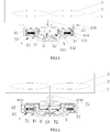
- the automatic washing machine of the present disclosure includes an outer tub 1, an inner tub 2, a pulsator 3 and a driving means.
- the driving means comprises two rotors 41, 42, a stator 43 and a deceleration mechanism 5, one rotor 41 drives the pulsator 3 to rotate after decelerated through the deceleration mechanism 5, the other rotor 42 drives the inner tub 2 to rotate as a same speed as the rotor 42 itself.
- the washing machine of the present disclosure controls the two rotors 41, 42 to respectively drive the pulsator 3 and the inner tub 2 to rotate in the same direction with different rotation speed, or the pulsator 3 and the inner tub 2 to rotate reversely during the washing process.
- the two rotors 41, 42 drive the pulsator 3 and the inner tub 2 to rotate in the same direction with the same speed during the dehydration process.
- the deceleration mechanism 5 of the present embodiment comprises a rotatable housing 51, a gear mechanism 6 arranged in the housing 51, an inner tub shaft 21, a pulsator shaft 31 and an input shaft 52.
- the housing 51 and the gear mechanism 6 rotate relatively independently.
- the inner tub shaft 21 is a sleeve structure, one end of which is connected to the inner tub 2, and the other end thereof is connected to the housing 51.
- the housing 51 is connected with the rotor 42.
- the pulsator shaft 31 is coaxially disposed in the inner tub shaft 21, one end is connected to the pulsator 3, and the other end is connected with a power output end of the gear mechanism 6.
- One end of the input shaft 52 is connected to the rotor 41 and the other end thereof is connected to the power input end of the gear mechanism 6.
- the two rotors of the direct drive motor 4 are respectively an inner rotor 41 and an outer rotor 42.
- the stator 43 is a disc-shaped structure with a downward concave center, which in turn comprises from inside to outside a central bearing housing 431, an inner rotor mounting groove 432 with a downward opening, a stator winding 433, an outer rotor mounting groove 434 with an upward opening, and a mounting base 435 which is at an outer edge and relatively fixed to the outer tub.
- the deceleration mechanism 5 is located at the downward concave center of the stator 43, and the outer rotor 42 is arranged above the stator 43 to match the shape of the stator 43.
- a center of the outer rotor 42 has a cavity for accommodating the deceleration mechanism, and an inner wall of the cavity is connected with the housing 51 of the deceleration mechanism.
- the inner rotor 41 is disposed below the stator 43 and is connected to the input shaft 52.
- the gear mechanism 6 of the deceleration mechanism of the present embodiment comprises a sun gear 61, an internal ring gear 62 and a planetary gear 63 meshing with the sun gear 61 and the internal ring gear 62 respectively.
- the sun gear 61 is mounted on the input shaft 52.
- a plurality of planetary gears 63 are provided and which are mounted on a planet wheel carrier 64, and the planet wheel carrier 64 is connected with the pulsator shaft 31.
- a lower end of the internal ring gear 62 is provided with a lower end cover 65, the lower end cover 65 is directly connected with an upper surface of the stator 43. (see Fig. 1 ).
- the lower end cover is connected with an input sleeve 53, the input sleeve 53 is arranged outside of the input shaft 52, and the input sleeve 53 is spline-connected with the stator 43.
- a reduction ratio of the deceleration mechanism is in a range from 1/10 to 1/2, the reduction ratio of 1/5 is taken as an example, and the deceleration mechanism engages with the direct drive motor 4 of the embodiment 1.
- the inner rotor 41 rotates forward at a speed of 600 rev/min and the input shaft 52 rotates forward to drive the sun gear 61 to rotate forward.
- the pulsator shaft 31 rotates forward at a speed of 120 rev/min.
- the outer rotor 42 drives the inner tub shaft 21 to rotate reversely at a speed of 100 rev/min, a double power washing system in which the inner tub 2 and the pulsator 3 rotate reversely is formed.
- the outer rotor 42 drives the inner tub shaft 21 to rotate forward at a speed of 80 rev/min so that the inner tub 2 and the pulsator 3 rotate in the same direction with different rotation speed to wash.
- the inner rotor 41 is driven to rotate in the same direction as the outer rotor 42 at a speed five times faster than the one of the outer rotor 42.
- the gear mechanism 6 of the deceleration mechanism comprises a central gear 66, an internal ring gear 62 and a transmission gear 67 meshing with the central gear 66 and the internal ring gear 62 respectively.
- the central gear 66 is mounted on the input shaft 52
- the internal ring gear 62 is connected with the pulsator shaft 31
- the transmission gear 67 is mounted on a lower end cover 65 through a gear shaft
- the lower end cover 65 is connected directly to an upper surface of the stator 43(see Fig. 1 ).
- the lower end cover is connected to an input sleeve 53, the input sleeve 53 is arranged outside the input shaft 52, and the input sleeve 53 is spline-connected with the stator 43(see Fig. 2 ).
- the deceleration mechanism with the reduction ratio of 1/6 is taken as an example, in combination with the direct drive motor 4 of the embodiment 1.
- the inner rotor 1 rotates forward at a speed of 600 rev/min
- the input shaft 52 rotates forward, which drives the central gear 66 to rotate forward.
- the pulsator shaft 31 rotates reversely at a speed of 100 rev/min.
- the outer rotor 42 drives the inner tub shaft 21 to rotate forward at a speed of 100 rev/min, a double power washing system in which the inner tub 2 and the pulsator 3 rotate reversely is formed.
- the outer rotor rotates at a speed of 80 rev/min to drive the inner tub shaft 21 to rotate reversely, so that the inner tub 2 and the pulsator 3 rotate in the same direction with different speed.
- the inner rotor 41 is driven to rotate in different direction from the outer rotor 42 at a speed five times faster than the one of the rotor 42.
- the gear mechanism 6 of the deceleration mechanism of the present embodiment comprises an input gear 68, an output gear 69, and a transmission gear 60 meshing with the input gear 68 and the output gear 69 respectively.
- the input gear 68 is mounted on the input shaft 52
- the output gear 69 is mounted on the pulsator shaft 31.
- the transmission gear 60 is a double gear including an upper gear 601 and a lower gear 602.
- the upper gear 601 meshes with the output gear 69 and the lower gear 602 meshes with the input gear 68.
- the transmission gear 60 is mounted on a lower end cover 65 through a gear shaft, the lower end cover is connected directly to an upper surface of the stator (see Fig. 1 ). Or, the lower end cover is connected with an input sleeve 53.
- the input sleeve 53 is arranged outside the input shaft 52
- the input sleeve 53 is spline-connected with the stator 43(see Fig. 2 ).
- the deceleration mechanism of the embodiment with the reduction ratio of 1/4 is taken as an example, and to engage with the direct drive motor 4 of the embodiment 1.
- the inner rotor rotates forward at a speed of 600 rev/min
- the input shaft 52 rotates forward, which drives the input gear 68 to rotate forward.
- the pulsator 31 rotates forward at a speed of 120 rev/min.
- the outer rotor 42 drives the inner tub shaft 21 to rotate reversely at a speed of 90 rev/min, a double power washing system in which the inner tub 2 and the pulsator 3 rotate reversely is formed.
- the outer rotor 42 drives the inner tub shaft 21 to rotate forward at a speed of 80 rev/min, so that the inner tub 2 and the pulsator 3 rotate in the same direction with different speed to wash.
- the inner rotor 41 is driven to rotate in the same direction as the outer rotor 42 at a speed five times faster than the outer rotor 42.
- the gear mechanism in the deceleration mechanism according to the present disclosure is not limited to the structures in the embodiments from 2 to 4, and other gear transmission structures capable of achieving output deceleration are suitable for use in the present disclosure.
- the structure of the two rotors of the present disclosure is likewise not limited to the structure of the embodiments.
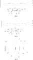
- Such as the deceleration mechanism in embodiment 1 can also be an independent structure, see Fig. 8 .
- the deceleration mechanism of the present scheme may be an independent structure, which comprises a housing 51, an input shaft 52, an output shaft 31 and a gear mechanism.
- the housing 51 and the stator 43 are integrally fixed.
- the lower end cover 65 of the deceleration mechanism is integrally mounted on the housing 51, and the other gear transmission relations are the same as those of the above schemes.
- the two rotors drive the pulsator and the inner tub to rotate in a same direction or in oppositional direction to each other.
- the pulsator and the inner tub rotates in the same direction with the same rotation speed.
- the two rotors first rotate for a set time, the inner tub and the pulsator rotate in the same direction, then the rotor that drives the pulsator to rotate is controlled to be in a free state, and only the rotor that drives the inner tub to rotate is controlled to rotate at a high speed.
- the rotor that drives the pulsator to rotate and the rotor that drives the inner tub to rotate are controlled to rotate at the same time, and maintain the inner tub and the pulsator rotating in the same direction at the same speed in the whole dehydration process.
Landscapes
- Engineering & Computer Science (AREA)
- Textile Engineering (AREA)
- Power Engineering (AREA)
- Main Body Construction Of Washing Machines And Laundry Dryers (AREA)
- Control Of Washing Machine And Dryer (AREA)
- Accessory Of Washing/Drying Machine, Commercial Washing/Drying Machine, Other Washing/Drying Machine (AREA)
Claims (8)
- Automatische Waschmaschine, umfassend eine Außentrommel (1), eine Innentrommel (2), einen Pulsator (3) und ein Antriebsmittel,
wobei das Antriebsmittel zwei Rotoren (41; 42), einen Stator (43) und einen Verzögerungsmechanismus (5) umfasst, ein Rotor (41) den Pulsator (3) zur Drehung nach einer Verzögerung durch den Verzögerungsmechanismus (5) antreibt und der andere Rotor (42) die Innentrommel (2) zur Drehung mit derselben Drehzahl wie der andere Rotor (42) antreibt, wobei der Verzögerungsmechanismus (5) ein drehbares Gehäuse (51) und einen im Gehäuse (51) angeordneten Getriebemechanismus (6), eine Innentrommelwelle (21), eine Pulsatorwelle (31) und eine Eingangswelle (52) umfasst,
die Innentrommelwelle (21) eine Wellenhülsenstruktur ist, ein Ende mit der Innentrommel (2) verbunden ist und das andere Ende mit dem Gehäuse (51) verbunden ist, das Gehäuse (51) mit dem einen Rotor (42) verbunden ist,
die Pulsatorwelle (31) koaxial in der Innentrommelwelle (21) angeordnet ist, ein Ende mit dem Pulsator (3) verbunden ist und das andere Ende mit einem Ausgang des Getriebemechanismus (6) verbunden ist,
ein Ende der Eingangswelle (52) mit dem anderen Rotor (41) verbunden ist, das andere Ende der Eingangswelle (52) mit einem Leistungseingangsende des Getriebemechanismus (6) verbunden ist,
dadurch gekennzeichnet, dass
die beiden Rotoren ein Innenrotor (41) und ein Außenrotor (42) sind,
der Stator (43) eine scheibenförmige Struktur mit einer nach unten konkaven Mitte ist,
der Stator, in der Reihenfolge von der Eingangswelle (52) nach außen, ein Zentrallagergehäuse (431), eine Innenrotorbefestigungsnut (432) mit einer nach unten weisenden Öffnung, eine Statorwicklung (433), eine Außenrotorbefestigungsnut (434) mit einer nach oben weisenden Öffnung und eine Befestigungsbasis (435), die sich an einer Außenkante befindet und mit der Außentrommel (1) relativ feststehend ist, umfasst
der Verzögerungsmechanismus (5) sich an der nach unten konkaven Mitte des Stators (43) befindet und der Außenrotor (42) über dem Stator (43) angeordnet ist, um der Form des Stators (43) zu entsprechen,
eine Mitte des Außenrotors einen Hohlraum zum Aufnehmen des Verzögerungsmechanismus (6) aufweist und eine Innenwand des Hohlraums mit dem Gehäuse (51) des Verzögerungsmechanismus (6) verbunden ist, der Innenrotor (41) unter dem Stator (43) angeordnet ist und mit der Eingangswelle (52) verbunden ist. - Automatische Waschmaschine nach Anspruch 1, wobei der Getriebemechanismus (6) ein Sonnenrad (61), ein Hohlrad (62) und ein Planetenrad (62), das mit dem Sonnenrad (61) bzw. dem Hohlrad (62) kämmt, umfasst,
das Sonnenrad (61) an der Eingangswelle (52) befestigt ist, das Planetenrad (62) an einem Planetenradträger (64) befestigt ist,
der Planetenradträger (64) mit der Pulsatorwelle (31) verbunden ist,
ein unteres Ende des Hohlrads (62) mit einer unteren Endabdeckung (65) bereitgestellt ist, die untere Endabdeckung (65) unmittelbar oder mittelbar mit dem Stator (43) verbunden ist. - Automatische Waschmaschine nach Anspruch 1, wobei der Getriebemechanismus (6) ein Zentralrad (66), ein Hohlrad (62) und ein Getrieberad (67), das mit dem Zentralrad (66) bzw. dem Hohlrad (62) kämmt, umfasst,
das Zentralrad (66) an der Eingangswelle (52) befestigt ist,
das Hohlrad (62) mit der Pulsatorwelle (31) verbunden ist,
das Getrieberad (67) an einer unteren Endabdeckung (65) durch eine Getriebewelle befestigt ist, die untere Endabdeckung unmittelbar oder mittelbar mit dem Stator (43) verbunden ist. - Automatische Waschmaschine nach Anspruch 1, wobei der Getriebemechanismus (6) ein Eingangsrad (68), ein Ausgangsrad (69) und ein Getrieberad (60), das mit dem Eingangsrad (68) bzw. dem Ausgangsrad (69) kämmt, umfasst,
das Eingangsrad (68) an der Eingangswelle (52) befestigt ist,
das Ausgangsrad (69) an der Pulsatorwelle (31) befestigt ist,
das Getrieberad (60) ein Doppelrad ist, das ein oberes Rad (601) und ein unteres Rad (602) einschließt, das obere Rad (601) mit dem Ausgangsrad (69) kämmt und das untere Rad (602) mit dem Eingangsrad (68) kämmt,
das Getrieberad (60) an einer unteren Endabdeckung (65) durch eine Getriebewelle befestigt ist, die untere Endabdeckung (65) unmittelbar oder mittelbar mit dem Stator (43) verbunden ist. - Automatische Waschmaschine nach einem der Ansprüche 2 bis 4, wobei die untere Endabdeckung (65) mit einer Eingangshülle (53) verbunden ist, die Eingangshülle (53) außerhalb der Eingangswelle (52) angeordnet ist und die Eingangshülle (53) mit dem Stator (43) keilverbunden ist.
- Automatische Waschmaschine nach einem der Ansprüche 1 bis 4, wobei der Verzögerungsmechanismus (5) ein Reduktionsverhältnis in einem Bereich von 1/10 bis 1/2 aufweist.
- Verfahren zur Steuerung der automatischen Waschmaschine nach einem der Ansprüche 1 bis 6, umfassend: die beiden Rotoren (41; 42) treiben während eines Waschvorgangs den Pulsator (3) und die Innentrommel (2) zum Drehen in einer selben Richtung oder zum Drehen in einander entgegengesetzten Richtungen an,
der Pulsator (3) und die Innentrommel (2) drehen sich während eines Entwässerungsvorgangs in einer selben Richtung mit einer selben Drehzahl. - Verfahren zur Steuerung der automatischen Waschmaschine nach Anspruch 7, wobei während des Entwässerungsvorgangs die beiden Rotoren (41; 42) sich zunächst über eine eingestellte Zeit drehen, die Innentrommel (2) und der Pulsator (3) sich in derselben Richtung drehen, dann der Rotor (41), der den Pulsator (3) zum Drehen antreibt, gesteuert wird, um in einem Freizustand zu sein, und nur der Rotor (42), der die Innentrommel (2) zum Drehen antreibt, mit einer hohen Geschwindigkeit gesteuert wird.
Applications Claiming Priority (2)
| Application Number | Priority Date | Filing Date | Title |
|---|---|---|---|
| CN201410425002.5A CN105401377B (zh) | 2014-08-26 | 2014-08-26 | 全自动洗衣机及控制方法 |
| PCT/CN2014/091404 WO2016029563A1 (zh) | 2014-08-26 | 2014-11-18 | 全自动洗衣机及控制方法 |
Publications (3)
| Publication Number | Publication Date |
|---|---|
| EP3187643A1 EP3187643A1 (de) | 2017-07-05 |
| EP3187643A4 EP3187643A4 (de) | 2017-08-16 |
| EP3187643B1 true EP3187643B1 (de) | 2018-12-12 |
Family
ID=55398704
Family Applications (1)
| Application Number | Title | Priority Date | Filing Date |
|---|---|---|---|
| EP14900370.9A Not-in-force EP3187643B1 (de) | 2014-08-26 | 2014-11-18 | Vollautomatische waschmaschine und steuerungsverfahren |
Country Status (6)
| Country | Link |
|---|---|
| US (1) | US10612179B2 (de) |
| EP (1) | EP3187643B1 (de) |
| JP (1) | JP6452069B2 (de) |
| KR (1) | KR102278276B1 (de) |
| CN (1) | CN105401377B (de) |
| WO (1) | WO2016029563A1 (de) |
Families Citing this family (23)
| Publication number | Priority date | Publication date | Assignee | Title |
|---|---|---|---|---|
| US10326323B2 (en) | 2015-12-11 | 2019-06-18 | Whirlpool Corporation | Multi-component rotor for an electric motor of an appliance |
| US11255036B2 (en) | 2016-07-28 | 2022-02-22 | Samsung Electronics Co., Ltd. | Washing machine |
| US10704180B2 (en) | 2016-09-22 | 2020-07-07 | Whirlpool Corporation | Reinforcing cap for a tub rear wall of an appliance |
| US10693336B2 (en) | 2017-06-02 | 2020-06-23 | Whirlpool Corporation | Winding configuration electric motor |
| CN107313210A (zh) * | 2017-06-15 | 2017-11-03 | 广西科技大学鹿山学院 | 分层式洗衣机 |
| EP3701075B1 (de) * | 2017-12-20 | 2022-02-16 | Samsung Electronics Co., Ltd. | Waschmaschine und motor |
| CN108611803B (zh) * | 2018-04-27 | 2024-03-01 | 广东威灵电机制造有限公司 | 滚筒洗衣机 |
| CN109487500A (zh) * | 2018-11-16 | 2019-03-19 | 惠而浦(中国)股份有限公司 | 一种双电机直驱全自动洗衣机 |
| CN109629175A (zh) * | 2018-11-16 | 2019-04-16 | 惠而浦(中国)股份有限公司 | 一种复合式多动力驱动装置 |
| CN111197224B (zh) * | 2018-11-20 | 2022-04-29 | 无锡小天鹅电器有限公司 | 洗衣机 |
| CN111764091B (zh) * | 2019-04-01 | 2022-07-19 | 青岛海尔洗衣机有限公司 | 一种波轮洗衣机及其控制方法 |
| CN111850942B (zh) * | 2019-04-01 | 2022-07-19 | 青岛海尔洗衣机有限公司 | 一种洗衣机的控制方法 |
| US11773525B2 (en) | 2019-05-02 | 2023-10-03 | Whirlpool Corporation | Double-rotor washing type drum washing machine |
| US11329537B2 (en) * | 2019-05-02 | 2022-05-10 | X Development Llc | Super-synchronous motor/generator |
| CN110629447B (zh) * | 2019-07-10 | 2024-07-16 | 青岛海尔洗衣机有限公司 | 波轮洗衣机 |
| CN112746459A (zh) * | 2019-10-16 | 2021-05-04 | 青岛海尔洗衣机有限公司 | 一种洗衣机及其控制方法 |
| CN112663289A (zh) * | 2019-10-16 | 2021-04-16 | 青岛海尔洗衣机有限公司 | 一种洗衣机及其控制方法 |
| CN112663276A (zh) * | 2019-10-16 | 2021-04-16 | 青岛海尔洗衣机有限公司 | 一种洗衣机及其控制方法 |
| CN112746458A (zh) * | 2019-10-16 | 2021-05-04 | 青岛海尔洗衣机有限公司 | 一种洗衣机及其控制方法 |
| CN112532000A (zh) * | 2020-11-27 | 2021-03-19 | 李亚兵 | 新型直流无楞次特效发电机 |
| KR102503953B1 (ko) * | 2021-01-29 | 2023-02-27 | 엘지전자 주식회사 | 의류처리장치 |
| CN116770558A (zh) * | 2022-03-10 | 2023-09-19 | 青岛海尔洗衣机有限公司 | 一种用于双驱动洗衣机的齿轮组结构 |
| CN118854608B (zh) * | 2023-04-27 | 2026-01-30 | 无锡小天鹅电器有限公司 | 衣物处理设备及其控制方法、装置和存储介质 |
Family Cites Families (17)
| Publication number | Priority date | Publication date | Assignee | Title |
|---|---|---|---|---|
| JPS59108595A (ja) * | 1982-12-13 | 1984-06-23 | 松下電器産業株式会社 | 遠心脱水洗濯機 |
| JPS59108596A (ja) * | 1982-12-13 | 1984-06-23 | 松下電器産業株式会社 | 遠心脱水洗濯機 |
| KR0130534B1 (ko) * | 1994-07-12 | 1998-04-09 | 김광호 | 세탁기용 리니어 모터 |
| CN1151596C (zh) | 2000-07-12 | 2004-05-26 | 北京东方渴望科技发展有限公司 | 洗衣机动力直驱装置 |
| KR100469256B1 (ko) * | 2002-05-14 | 2005-02-02 | 엘지전자 주식회사 | 세탁기 구동부의 방진구조 |
| US6834407B2 (en) * | 2002-12-17 | 2004-12-28 | General Electric Company | Method and apparatus for electronically commutated motor washer agitation controller |
| KR100504867B1 (ko) * | 2003-01-16 | 2005-07-29 | 엘지전자 주식회사 | 인덕션모터를 구비한 드럼 세탁기 |
| DE602004031407D1 (de) * | 2003-02-06 | 2011-03-31 | Lg Electronics Inc | Waschmaschine |
| KR20060020265A (ko) * | 2004-08-31 | 2006-03-06 | 엘지전자 주식회사 | 세탁기의 구동부 및 그 제어방법 |
| US20060042022A1 (en) | 2004-08-31 | 2006-03-02 | Lg Electronics Inc. | Washing machine and method for controlling the same |
| KR101343580B1 (ko) * | 2007-01-04 | 2013-12-19 | 엘지전자 주식회사 | 모터 및 이를 구비한 드럼 세탁기 |
| KR101228043B1 (ko) * | 2011-06-08 | 2013-01-30 | 주식회사 아모텍 | 직결식 세탁기의 구동장치 |
| KR101368243B1 (ko) * | 2011-11-10 | 2014-02-27 | 주식회사 아모텍 | 세탁기용 모터, 세탁기 모터 제조방법 및 이를 구비한 세탁기 |
| CN102877269B (zh) * | 2012-10-22 | 2015-09-16 | 安徽聚隆传动科技股份有限公司 | 一种洗衣机电机直驱传动减速机构 |
| WO2014112839A1 (ko) * | 2013-01-21 | 2014-07-24 | 주식회사 아모텍 | 다중 모터 구동장치와 이를 이용한 세탁기용 모터 구동장치 및 그 방법 |
| CN203530710U (zh) | 2013-05-10 | 2014-04-09 | 海尔集团公司 | 全自动洗衣机 |
| CN204138927U (zh) * | 2014-08-26 | 2015-02-04 | 青岛海尔洗衣机有限公司 | 全自动洗衣机 |
-
2014
- 2014-08-26 CN CN201410425002.5A patent/CN105401377B/zh active Active
- 2014-11-18 JP JP2017508646A patent/JP6452069B2/ja active Active
- 2014-11-18 EP EP14900370.9A patent/EP3187643B1/de not_active Not-in-force
- 2014-11-18 KR KR1020177007713A patent/KR102278276B1/ko active Active
- 2014-11-18 WO PCT/CN2014/091404 patent/WO2016029563A1/zh not_active Ceased
- 2014-11-18 US US15/505,364 patent/US10612179B2/en active Active
Non-Patent Citations (1)
| Title |
|---|
| None * |
Also Published As
| Publication number | Publication date |
|---|---|
| KR102278276B1 (ko) | 2021-07-16 |
| JP2017529141A (ja) | 2017-10-05 |
| WO2016029563A1 (zh) | 2016-03-03 |
| EP3187643A1 (de) | 2017-07-05 |
| CN105401377A (zh) | 2016-03-16 |
| US10612179B2 (en) | 2020-04-07 |
| KR20170044700A (ko) | 2017-04-25 |
| CN105401377B (zh) | 2019-08-27 |
| EP3187643A4 (de) | 2017-08-16 |
| JP6452069B2 (ja) | 2019-01-16 |
| US20170268150A1 (en) | 2017-09-21 |
Similar Documents
| Publication | Publication Date | Title |
|---|---|---|
| US10612179B2 (en) | Automatic washing machine and control method | |
| CN104141212B (zh) | 全自动洗衣机 | |
| CN108708137B (zh) | 一种洗衣机减速离合装置及洗衣机 | |
| CN101153436B (zh) | 双波轮多动力全自动洗衣机 | |
| CN104674507B (zh) | 全自动洗衣机减速离合器 | |
| CN102296439B (zh) | 直驱双动力全自动洗衣机 | |
| CN204138927U (zh) | 全自动洗衣机 | |
| JP2017505644A (ja) | 洗濯機の洗濯方法およびその洗濯機 | |
| CN102767060A (zh) | 一种多波轮洗衣机洗涤方法及洗衣机 | |
| KR100463545B1 (ko) | 드럼세탁기 | |
| CN104032542A (zh) | 一种双输出滚筒洗衣机减速离合器及其洗衣机 | |
| CN207958780U (zh) | 一种洗衣机 | |
| CN1282132A (zh) | 洗衣机动力直驱装置 | |
| CN203530710U (zh) | 全自动洗衣机 | |
| CN105375682B (zh) | 双转子直驱电机 | |
| CN2441829Y (zh) | 洗衣机动力直驱装置 | |
| CN204258536U (zh) | 双转子直驱电机 | |
| CN205024470U (zh) | 一种滚筒洗衣机减速离合器与滚筒洗衣机 | |
| CN200992648Y (zh) | 双波轮多动力全自动洗衣机 | |
| WO2020200225A1 (zh) | 一种波轮洗衣机及其控制方法 | |
| JP2010094248A (ja) | 洗濯機 | |
| CN106637825B (zh) | 一种滚筒洗衣机减速离合器与滚筒洗衣机及洗涤方法 | |
| CN210856682U (zh) | 一种减速离合器及洗衣机 | |
| CN209443247U (zh) | 一种双电机直驱全自动洗衣机 | |
| KR20030008351A (ko) | 드럼 세탁기 |
Legal Events
| Date | Code | Title | Description |
|---|---|---|---|
| STAA | Information on the status of an ep patent application or granted ep patent |
Free format text: STATUS: THE INTERNATIONAL PUBLICATION HAS BEEN MADE |
|
| PUAI | Public reference made under article 153(3) epc to a published international application that has entered the european phase |
Free format text: ORIGINAL CODE: 0009012 |
|
| STAA | Information on the status of an ep patent application or granted ep patent |
Free format text: STATUS: REQUEST FOR EXAMINATION WAS MADE |
|
| 17P | Request for examination filed |
Effective date: 20170313 |
|
| AK | Designated contracting states |
Kind code of ref document: A1 Designated state(s): AL AT BE BG CH CY CZ DE DK EE ES FI FR GB GR HR HU IE IS IT LI LT LU LV MC MK MT NL NO PL PT RO RS SE SI SK SM TR |
|
| AX | Request for extension of the european patent |
Extension state: BA ME |
|
| RIC1 | Information provided on ipc code assigned before grant |
Ipc: D06F 37/40 20060101AFI20170706BHEP |
|
| A4 | Supplementary search report drawn up and despatched |
Effective date: 20170717 |
|
| DAX | Request for extension of the european patent (deleted) | ||
| RIC1 | Information provided on ipc code assigned before grant |
Ipc: H02K 16/02 20060101ALN20180620BHEP Ipc: H02K 7/116 20060101ALN20180620BHEP Ipc: D06F 37/40 20060101AFI20180620BHEP Ipc: D06F 37/30 20060101ALN20180620BHEP |
|
| GRAP | Despatch of communication of intention to grant a patent |
Free format text: ORIGINAL CODE: EPIDOSNIGR1 |
|
| STAA | Information on the status of an ep patent application or granted ep patent |
Free format text: STATUS: GRANT OF PATENT IS INTENDED |
|
| RIC1 | Information provided on ipc code assigned before grant |
Ipc: H02K 16/02 20060101ALN20180627BHEP Ipc: D06F 37/40 20060101AFI20180627BHEP Ipc: D06F 37/30 20060101ALN20180627BHEP Ipc: H02K 7/116 20060101ALN20180627BHEP |
|
| INTG | Intention to grant announced |
Effective date: 20180730 |
|
| GRAS | Grant fee paid |
Free format text: ORIGINAL CODE: EPIDOSNIGR3 |
|
| GRAA | (expected) grant |
Free format text: ORIGINAL CODE: 0009210 |
|
| STAA | Information on the status of an ep patent application or granted ep patent |
Free format text: STATUS: THE PATENT HAS BEEN GRANTED |
|
| AK | Designated contracting states |
Kind code of ref document: B1 Designated state(s): AL AT BE BG CH CY CZ DE DK EE ES FI FR GB GR HR HU IE IS IT LI LT LU LV MC MK MT NL NO PL PT RO RS SE SI SK SM TR |
|
| REG | Reference to a national code |
Ref country code: GB Ref legal event code: FG4D |
|
| REG | Reference to a national code |
Ref country code: CH Ref legal event code: EP |
|
| REG | Reference to a national code |
Ref country code: AT Ref legal event code: REF Ref document number: 1076108 Country of ref document: AT Kind code of ref document: T Effective date: 20181215 |
|
| REG | Reference to a national code |
Ref country code: DE Ref legal event code: R096 Ref document number: 602014038044 Country of ref document: DE |
|
| REG | Reference to a national code |
Ref country code: IE Ref legal event code: FG4D |
|
| REG | Reference to a national code |
Ref country code: NL Ref legal event code: MP Effective date: 20181212 |
|
| REG | Reference to a national code |
Ref country code: LT Ref legal event code: MG4D |
|
| PG25 | Lapsed in a contracting state [announced via postgrant information from national office to epo] |
Ref country code: NO Free format text: LAPSE BECAUSE OF FAILURE TO SUBMIT A TRANSLATION OF THE DESCRIPTION OR TO PAY THE FEE WITHIN THE PRESCRIBED TIME-LIMIT Effective date: 20190312 Ref country code: BG Free format text: LAPSE BECAUSE OF FAILURE TO SUBMIT A TRANSLATION OF THE DESCRIPTION OR TO PAY THE FEE WITHIN THE PRESCRIBED TIME-LIMIT Effective date: 20190312 Ref country code: LT Free format text: LAPSE BECAUSE OF FAILURE TO SUBMIT A TRANSLATION OF THE DESCRIPTION OR TO PAY THE FEE WITHIN THE PRESCRIBED TIME-LIMIT Effective date: 20181212 Ref country code: FI Free format text: LAPSE BECAUSE OF FAILURE TO SUBMIT A TRANSLATION OF THE DESCRIPTION OR TO PAY THE FEE WITHIN THE PRESCRIBED TIME-LIMIT Effective date: 20181212 Ref country code: ES Free format text: LAPSE BECAUSE OF FAILURE TO SUBMIT A TRANSLATION OF THE DESCRIPTION OR TO PAY THE FEE WITHIN THE PRESCRIBED TIME-LIMIT Effective date: 20181212 Ref country code: LV Free format text: LAPSE BECAUSE OF FAILURE TO SUBMIT A TRANSLATION OF THE DESCRIPTION OR TO PAY THE FEE WITHIN THE PRESCRIBED TIME-LIMIT Effective date: 20181212 Ref country code: HR Free format text: LAPSE BECAUSE OF FAILURE TO SUBMIT A TRANSLATION OF THE DESCRIPTION OR TO PAY THE FEE WITHIN THE PRESCRIBED TIME-LIMIT Effective date: 20181212 |
|
| REG | Reference to a national code |
Ref country code: AT Ref legal event code: MK05 Ref document number: 1076108 Country of ref document: AT Kind code of ref document: T Effective date: 20181212 |
|
| PG25 | Lapsed in a contracting state [announced via postgrant information from national office to epo] |
Ref country code: AL Free format text: LAPSE BECAUSE OF FAILURE TO SUBMIT A TRANSLATION OF THE DESCRIPTION OR TO PAY THE FEE WITHIN THE PRESCRIBED TIME-LIMIT Effective date: 20181212 Ref country code: SE Free format text: LAPSE BECAUSE OF FAILURE TO SUBMIT A TRANSLATION OF THE DESCRIPTION OR TO PAY THE FEE WITHIN THE PRESCRIBED TIME-LIMIT Effective date: 20181212 Ref country code: RS Free format text: LAPSE BECAUSE OF FAILURE TO SUBMIT A TRANSLATION OF THE DESCRIPTION OR TO PAY THE FEE WITHIN THE PRESCRIBED TIME-LIMIT Effective date: 20181212 Ref country code: GR Free format text: LAPSE BECAUSE OF FAILURE TO SUBMIT A TRANSLATION OF THE DESCRIPTION OR TO PAY THE FEE WITHIN THE PRESCRIBED TIME-LIMIT Effective date: 20190313 |
|
| PG25 | Lapsed in a contracting state [announced via postgrant information from national office to epo] |
Ref country code: NL Free format text: LAPSE BECAUSE OF FAILURE TO SUBMIT A TRANSLATION OF THE DESCRIPTION OR TO PAY THE FEE WITHIN THE PRESCRIBED TIME-LIMIT Effective date: 20181212 |
|
| PG25 | Lapsed in a contracting state [announced via postgrant information from national office to epo] |
Ref country code: PL Free format text: LAPSE BECAUSE OF FAILURE TO SUBMIT A TRANSLATION OF THE DESCRIPTION OR TO PAY THE FEE WITHIN THE PRESCRIBED TIME-LIMIT Effective date: 20181212 Ref country code: PT Free format text: LAPSE BECAUSE OF FAILURE TO SUBMIT A TRANSLATION OF THE DESCRIPTION OR TO PAY THE FEE WITHIN THE PRESCRIBED TIME-LIMIT Effective date: 20190412 Ref country code: CZ Free format text: LAPSE BECAUSE OF FAILURE TO SUBMIT A TRANSLATION OF THE DESCRIPTION OR TO PAY THE FEE WITHIN THE PRESCRIBED TIME-LIMIT Effective date: 20181212 Ref country code: IT Free format text: LAPSE BECAUSE OF FAILURE TO SUBMIT A TRANSLATION OF THE DESCRIPTION OR TO PAY THE FEE WITHIN THE PRESCRIBED TIME-LIMIT Effective date: 20181212 |
|
| PG25 | Lapsed in a contracting state [announced via postgrant information from national office to epo] |
Ref country code: EE Free format text: LAPSE BECAUSE OF FAILURE TO SUBMIT A TRANSLATION OF THE DESCRIPTION OR TO PAY THE FEE WITHIN THE PRESCRIBED TIME-LIMIT Effective date: 20181212 Ref country code: SM Free format text: LAPSE BECAUSE OF FAILURE TO SUBMIT A TRANSLATION OF THE DESCRIPTION OR TO PAY THE FEE WITHIN THE PRESCRIBED TIME-LIMIT Effective date: 20181212 Ref country code: RO Free format text: LAPSE BECAUSE OF FAILURE TO SUBMIT A TRANSLATION OF THE DESCRIPTION OR TO PAY THE FEE WITHIN THE PRESCRIBED TIME-LIMIT Effective date: 20181212 Ref country code: SK Free format text: LAPSE BECAUSE OF FAILURE TO SUBMIT A TRANSLATION OF THE DESCRIPTION OR TO PAY THE FEE WITHIN THE PRESCRIBED TIME-LIMIT Effective date: 20181212 Ref country code: IS Free format text: LAPSE BECAUSE OF FAILURE TO SUBMIT A TRANSLATION OF THE DESCRIPTION OR TO PAY THE FEE WITHIN THE PRESCRIBED TIME-LIMIT Effective date: 20190412 |
|
| REG | Reference to a national code |
Ref country code: DE Ref legal event code: R097 Ref document number: 602014038044 Country of ref document: DE |
|
| PLBE | No opposition filed within time limit |
Free format text: ORIGINAL CODE: 0009261 |
|
| STAA | Information on the status of an ep patent application or granted ep patent |
Free format text: STATUS: NO OPPOSITION FILED WITHIN TIME LIMIT |
|
| PG25 | Lapsed in a contracting state [announced via postgrant information from national office to epo] |
Ref country code: AT Free format text: LAPSE BECAUSE OF FAILURE TO SUBMIT A TRANSLATION OF THE DESCRIPTION OR TO PAY THE FEE WITHIN THE PRESCRIBED TIME-LIMIT Effective date: 20181212 Ref country code: DK Free format text: LAPSE BECAUSE OF FAILURE TO SUBMIT A TRANSLATION OF THE DESCRIPTION OR TO PAY THE FEE WITHIN THE PRESCRIBED TIME-LIMIT Effective date: 20181212 Ref country code: SI Free format text: LAPSE BECAUSE OF FAILURE TO SUBMIT A TRANSLATION OF THE DESCRIPTION OR TO PAY THE FEE WITHIN THE PRESCRIBED TIME-LIMIT Effective date: 20181212 |
|
| 26N | No opposition filed |
Effective date: 20190913 |
|
| PG25 | Lapsed in a contracting state [announced via postgrant information from national office to epo] |
Ref country code: TR Free format text: LAPSE BECAUSE OF FAILURE TO SUBMIT A TRANSLATION OF THE DESCRIPTION OR TO PAY THE FEE WITHIN THE PRESCRIBED TIME-LIMIT Effective date: 20181212 |
|
| REG | Reference to a national code |
Ref country code: CH Ref legal event code: PL |
|
| PG25 | Lapsed in a contracting state [announced via postgrant information from national office to epo] |
Ref country code: LU Free format text: LAPSE BECAUSE OF NON-PAYMENT OF DUE FEES Effective date: 20191118 Ref country code: LI Free format text: LAPSE BECAUSE OF NON-PAYMENT OF DUE FEES Effective date: 20191130 Ref country code: CH Free format text: LAPSE BECAUSE OF NON-PAYMENT OF DUE FEES Effective date: 20191130 Ref country code: MC Free format text: LAPSE BECAUSE OF FAILURE TO SUBMIT A TRANSLATION OF THE DESCRIPTION OR TO PAY THE FEE WITHIN THE PRESCRIBED TIME-LIMIT Effective date: 20181212 |
|
| REG | Reference to a national code |
Ref country code: BE Ref legal event code: MM Effective date: 20191130 |
|
| PG25 | Lapsed in a contracting state [announced via postgrant information from national office to epo] |
Ref country code: IE Free format text: LAPSE BECAUSE OF NON-PAYMENT OF DUE FEES Effective date: 20191118 |
|
| PG25 | Lapsed in a contracting state [announced via postgrant information from national office to epo] |
Ref country code: BE Free format text: LAPSE BECAUSE OF NON-PAYMENT OF DUE FEES Effective date: 20191130 |
|
| PG25 | Lapsed in a contracting state [announced via postgrant information from national office to epo] |
Ref country code: CY Free format text: LAPSE BECAUSE OF FAILURE TO SUBMIT A TRANSLATION OF THE DESCRIPTION OR TO PAY THE FEE WITHIN THE PRESCRIBED TIME-LIMIT Effective date: 20181212 |
|
| PG25 | Lapsed in a contracting state [announced via postgrant information from national office to epo] |
Ref country code: HU Free format text: LAPSE BECAUSE OF FAILURE TO SUBMIT A TRANSLATION OF THE DESCRIPTION OR TO PAY THE FEE WITHIN THE PRESCRIBED TIME-LIMIT; INVALID AB INITIO Effective date: 20141118 Ref country code: MT Free format text: LAPSE BECAUSE OF FAILURE TO SUBMIT A TRANSLATION OF THE DESCRIPTION OR TO PAY THE FEE WITHIN THE PRESCRIBED TIME-LIMIT Effective date: 20181212 |
|
| PGFP | Annual fee paid to national office [announced via postgrant information from national office to epo] |
Ref country code: GB Payment date: 20211123 Year of fee payment: 8 Ref country code: DE Payment date: 20211021 Year of fee payment: 8 Ref country code: FR Payment date: 20211119 Year of fee payment: 8 |
|
| PG25 | Lapsed in a contracting state [announced via postgrant information from national office to epo] |
Ref country code: MK Free format text: LAPSE BECAUSE OF FAILURE TO SUBMIT A TRANSLATION OF THE DESCRIPTION OR TO PAY THE FEE WITHIN THE PRESCRIBED TIME-LIMIT Effective date: 20181212 |
|
| REG | Reference to a national code |
Ref country code: DE Ref legal event code: R119 Ref document number: 602014038044 Country of ref document: DE |
|
| GBPC | Gb: european patent ceased through non-payment of renewal fee |
Effective date: 20221118 |
|
| PG25 | Lapsed in a contracting state [announced via postgrant information from national office to epo] |
Ref country code: GB Free format text: LAPSE BECAUSE OF NON-PAYMENT OF DUE FEES Effective date: 20221118 Ref country code: DE Free format text: LAPSE BECAUSE OF NON-PAYMENT OF DUE FEES Effective date: 20230601 |
|
| PG25 | Lapsed in a contracting state [announced via postgrant information from national office to epo] |
Ref country code: FR Free format text: LAPSE BECAUSE OF NON-PAYMENT OF DUE FEES Effective date: 20221130 |