EP3185088B1 - Ensemble de commande d'un mecanisme d'affichage horloger - Google Patents
Ensemble de commande d'un mecanisme d'affichage horloger Download PDFInfo
- Publication number
- EP3185088B1 EP3185088B1 EP17151092.8A EP17151092A EP3185088B1 EP 3185088 B1 EP3185088 B1 EP 3185088B1 EP 17151092 A EP17151092 A EP 17151092A EP 3185088 B1 EP3185088 B1 EP 3185088B1
- Authority
- EP
- European Patent Office
- Prior art keywords
- arm
- wheel
- controlling
- clockwise direction
- pinion
- Prior art date
- Legal status (The legal status is an assumption and is not a legal conclusion. Google has not performed a legal analysis and makes no representation as to the accuracy of the status listed.)
- Active
Links
Images






Classifications
-
- G—PHYSICS
- G04—HOROLOGY
- G04B—MECHANICALLY-DRIVEN CLOCKS OR WATCHES; MECHANICAL PARTS OF CLOCKS OR WATCHES IN GENERAL; TIME PIECES USING THE POSITION OF THE SUN, MOON OR STARS
- G04B37/00—Cases
- G04B37/0083—Cases for more than one clockwork
-
- G—PHYSICS
- G04—HOROLOGY
- G04B—MECHANICALLY-DRIVEN CLOCKS OR WATCHES; MECHANICAL PARTS OF CLOCKS OR WATCHES IN GENERAL; TIME PIECES USING THE POSITION OF THE SUN, MOON OR STARS
- G04B13/00—Gearwork
- G04B13/02—Wheels; Pinions; Spindles; Pivots
-
- G—PHYSICS
- G04—HOROLOGY
- G04B—MECHANICALLY-DRIVEN CLOCKS OR WATCHES; MECHANICAL PARTS OF CLOCKS OR WATCHES IN GENERAL; TIME PIECES USING THE POSITION OF THE SUN, MOON OR STARS
- G04B19/00—Indicating the time by visual means
-
- G—PHYSICS
- G04—HOROLOGY
- G04B—MECHANICALLY-DRIVEN CLOCKS OR WATCHES; MECHANICAL PARTS OF CLOCKS OR WATCHES IN GENERAL; TIME PIECES USING THE POSITION OF THE SUN, MOON OR STARS
- G04B19/00—Indicating the time by visual means
- G04B19/02—Back-gearing arrangements between gear train and hands
-
- G—PHYSICS
- G04—HOROLOGY
- G04B—MECHANICALLY-DRIVEN CLOCKS OR WATCHES; MECHANICAL PARTS OF CLOCKS OR WATCHES IN GENERAL; TIME PIECES USING THE POSITION OF THE SUN, MOON OR STARS
- G04B19/00—Indicating the time by visual means
- G04B19/06—Dials
- G04B19/16—Shiftable dials, e.g. indicating alternately from 1 to 12 and from 13 to 24
-
- G—PHYSICS
- G04—HOROLOGY
- G04B—MECHANICALLY-DRIVEN CLOCKS OR WATCHES; MECHANICAL PARTS OF CLOCKS OR WATCHES IN GENERAL; TIME PIECES USING THE POSITION OF THE SUN, MOON OR STARS
- G04B19/00—Indicating the time by visual means
- G04B19/20—Indicating by numbered bands, drums, discs, or sheets
- G04B19/202—Indicating by numbered bands, drums, discs, or sheets by means of turning discs
-
- G—PHYSICS
- G04—HOROLOGY
- G04B—MECHANICALLY-DRIVEN CLOCKS OR WATCHES; MECHANICAL PARTS OF CLOCKS OR WATCHES IN GENERAL; TIME PIECES USING THE POSITION OF THE SUN, MOON OR STARS
- G04B19/00—Indicating the time by visual means
- G04B19/22—Arrangements for indicating different local apparent times; Universal time pieces
- G04B19/223—Arrangements for indicating different local apparent times; Universal time pieces with rotary disc, rotary bezel, or rotary dial
-
- G—PHYSICS
- G04—HOROLOGY
- G04B—MECHANICALLY-DRIVEN CLOCKS OR WATCHES; MECHANICAL PARTS OF CLOCKS OR WATCHES IN GENERAL; TIME PIECES USING THE POSITION OF THE SUN, MOON OR STARS
- G04B19/00—Indicating the time by visual means
- G04B19/24—Clocks or watches with date or week-day indicators, i.e. calendar clocks or watches; Clockwork calendars
- G04B19/243—Clocks or watches with date or week-day indicators, i.e. calendar clocks or watches; Clockwork calendars characterised by the shape of the date indicator
- G04B19/247—Clocks or watches with date or week-day indicators, i.e. calendar clocks or watches; Clockwork calendars characterised by the shape of the date indicator disc-shaped
-
- G—PHYSICS
- G04—HOROLOGY
- G04B—MECHANICALLY-DRIVEN CLOCKS OR WATCHES; MECHANICAL PARTS OF CLOCKS OR WATCHES IN GENERAL; TIME PIECES USING THE POSITION OF THE SUN, MOON OR STARS
- G04B27/00—Mechanical devices for setting the time indicating means
- G04B27/002—The setting apparatus being crown shaped
-
- G—PHYSICS
- G04—HOROLOGY
- G04B—MECHANICALLY-DRIVEN CLOCKS OR WATCHES; MECHANICAL PARTS OF CLOCKS OR WATCHES IN GENERAL; TIME PIECES USING THE POSITION OF THE SUN, MOON OR STARS
- G04B33/00—Calibers
-
- G—PHYSICS
- G04—HOROLOGY
- G04C—ELECTROMECHANICAL CLOCKS OR WATCHES
- G04C17/00—Indicating the time optically by electric means
- G04C17/005—Indicating the time optically by electric means by discs
-
- G—PHYSICS
- G04—HOROLOGY
- G04F—TIME-INTERVAL MEASURING
- G04F7/00—Apparatus for measuring unknown time intervals by non-electric means
- G04F7/04—Apparatus for measuring unknown time intervals by non-electric means using a mechanical oscillator
- G04F7/08—Watches or clocks with stop devices, e.g. chronograph
- G04F7/0823—Watches or clocks with stop devices, e.g. chronograph with couplings between the chronograph mechanism and the base movement
- G04F7/0828—Watches or clocks with stop devices, e.g. chronograph with couplings between the chronograph mechanism and the base movement acting in the plane of the movement
Definitions
- the present invention relates to mechanical timepieces. It relates more particularly to a mechanism for displaying several different time information items comprising several information carriers on each of which one of said time information items appears.
- the present invention relates to a control assembly for a timepiece, and in particular for a timepiece display mechanism.
- Such a mechanism for displaying several different horometric information items comprising several information media on each of which one of said horometric information items appears is traditionally used in mechanical timepieces in order to display, on the dial, different horometric information items, such as the date, the time according to different time zones, the phases of the moon, etc.
- This information is displayed by means of different windows or indexes distributed on the dial of the timepiece. Once the timepiece is built, the position of the different information displayed on the dial is immutable, so that it is not possible to modify the appearance of the dial.
- each information carrier and its operating mechanism take up a large amount of space under the dial, so that the dial and movement are very cluttered, which does not allow for other displays or other mechanisms due to lack of space.
- An aim of the present invention is therefore to overcome these drawbacks, by proposing a display mechanism making it possible to select the time information to be displayed.
- Another object of the present invention is to provide a display mechanism for displaying different time information in the same place on the dial, leaving space available for other displays or mechanisms.
- a control assembly is proposed for a timepiece, and in particular for a mechanism for displaying several different time information items comprising several information media on each of which one of said time information items appears.
- control assembly for a timepiece comprises a shaft, an arm mounted securely on a toothed actuating wheel mounted freely rotatable around said shaft and a control block. centralized pivoting around the shaft and configured to operate the arm in a clockwise and a counterclockwise direction.
- the control assembly further comprises the features of claim 1. Advantageous embodiments of this assembly are defined in the dependent claims.
- a clock movement 1 comprising a display mechanism, as well as a display of the minutes by means of a retrograde hand 2 and an arc 4 bearing the graduations of the minutes.
- the display mechanism comprises a frame on which a magazine 6 is provided in which said information carriers 8 are stored in an inactive storage position, a platform 10 arranged to receive, in a movably manner depending on the time information to be displayed, the selected information carrier 8 in an active operating position, first means 12 for moving the selected information carrier 8 between said inactive storage position in the magazine 6 and said active operating position on the platform 10, said first means 12 for moving being mounted between the magazine 6 and the platform 10, and means 14 for controlling said first means for moving.
- each information medium 8 comprises a disk 16 carrying time information.
- the time information can be represented in the form of graduations, numbers or any other suitable form and can correspond for example to a time according to a time zone, a date, a moon phase, etc. Indexes for locating the time information to be displayed are provided on the glass of the information medium. It is obvious that the reverse configuration is possible, the time information being represented in the form of an index shown on the disk 16, such as a hand, graduations being provided on the glass of the information medium.
- the disk 16 can be in the form of a solid disk or a disk having a central opening to form a coaxial ring with the other media information.
- Information carriers in the form of several concentric rings can be used, for example, to display a large date, with the units and tens digits positioned on two different rings.
- the platform is then arranged to rotate the rings simultaneously at their respective speeds.
- the rings can also bear any suitable pattern so that their respective drives by the platform form an animation.
- the disk carrying the time information is secured to a base 17 comprising on its bottom, directed outwards, first means for positioning said disk 16 carrying the time information on the platform 10.
- Said first means for positioning said disk 16 carrying the time information on the platform 10 are advantageously constituted by an oblong opening and by a circular orifice allowing respectively to receive a drive pin and a pointing pin provided on the platform 10 as will be seen below.
- the base 17 also comprises a circular groove 18 arranged to allow the free movement of the drive and pointing pins corresponding to another information support.
- the base 17 also includes an external peripheral tooth 20 whose function will be described below.
- the information support 8 also comprises a ring 22 inside which the disk 16 carrying the horometric information and its base 17 are arranged.
- the assembly is closed by means of a glass 24 on which are represented indexes 26 making it possible to locate the horometric information to be displayed.
- the disk 16 carrying the time information and its base 17 are mounted to rotate freely inside the ring 22 around a shaft 28 secured to the crystal 24 by means of a ball bearing 25.
- the ring 22 comprises housings constituting second positioning means 30 of the information support 8 in the magazine 6.
- the ring 22 further comprises housings 32 arranged to receive the first means of movement 12 of the selected information medium 8.
- the ring 22 also includes a cutout 34 arranged to allow the passage of the clutch means of the disc 16 as will be described below.
- the magazine 6 comprises a tray 36 on which are superimposed different housings 38 arranged to receive respectively an information medium 8.
- first actuation means 40 arranged to move the magazine 6 so as to present the selected information medium 8 at the first movement means. Said first actuation means 40 will be described below.
- the movement comprises a fixed chassis 42 inside which said magazine 6 is mounted mobile in translation perpendicular to the general plane of the movement, so as to be able to be moved and present the selected information medium 8 at the level of the first movement means.
- the magazine can be arranged so as to be mobile along a plane inclined relative to the general plane of the movement.
- the fixed chassis 42 comprises a lower bridge 44, an intermediate bridge (not shown) and an upper bridge 46 secured to the frame.
- the fixed frame 42 also comprises a first set of pins 48 mounted between the lower bridge 44 and the intermediate bridge, along which the plate 36 of the magazine 6 slides perpendicular to the general plane of movement.
- the fixed frame 42 also comprises a second set of pins 50 mounted between the lower bridge 44 and the upper bridge 46.
- the plate 36 of the magazine 6 as well as the information supports 8 are arranged to slide perpendicular to the general plane of movement along said second set of pins 50, said pins 50 being in particular introduced into the housings 30 provided on the ring 22 of the information medium 8.
- each pin 50 is interrupted to form a passage and allow the extraction of the selected information medium 8 from the magazine 6, as shown more specifically in Figure 4a .
- an information medium 52 mounted to rotate about an axis 54 mounted in the upper housing of the magazine 6.
- Such an information medium 52 is for example a disk comprising graduations allowing the display of the local time by means of an index provided on the glass protecting said disk. Said information medium 52 moves in translation with the other information media 8 stored in the magazine 6, but remains in its housing.
- Said information support 52 is integral with a crown 56 having external teeth 58. Furthermore, a shaft 59 (visible in the figures 1 And 2 ) pivotally mounted and comprising at its upper end a pinion 60 meshing with the external teeth 58 of the crown 56, and at the lower end a first element of a set of references kinematically connected to an hour wheel allowing the information support 52 to rotate at the speed of the hours.
- the pinion 60 is sufficiently long so that the external teeth 58 of the crown 56 remains meshed with said pinion 60 when the information support 52 slides with the magazine 6.
- the first actuating means 40 arranged to move the magazine 6 comprise a selection arm 62, accessible to a user and secured to a plate 240 pivotally mounted on the fixed chassis 42, such that the angular movement of the selection arm 62 causes the translational movement of the plate 36 of the magazine 6.
- a reduction gear train is provided comprising a pinion 64 pivotally mounted on the plate 240.
- Said pinion 64 meshes with an internal toothing 66 of a fixed wheel 68 provided on the frame and is also secured to a toothed wheel 70 cooperating with a toothed wheel 72 secured to a nut 74 having an internal thread 75.
- a screw 76 having an external thread arranged to cooperate with the internal thread 75 of the nut 74.
- an angular movement of the selection arm 62 causes an angular movement of the pinion 64 which, cooperating with the teeth 66, pivots on its axis, rotating the toothed wheel 70, itself rotating the toothed wheel 72 and the nut 74.
- the rotation of the nut 74 causes the translational movement of the screw 76, and therefore of the plate 36 and the magazine 6.
- the first means 12 for moving the selected information medium 8 comprise an arm 80 pivotally mounted between the magazine 6 and the platform 10, said arm 80 having means for gripping the selected information medium 8 arranged to extract the selected information medium from its housing 38 in the magazine 6.
- the arm 80 has the shape of a two-branched fork, the ends of which have protrusions 81 arranged to be housed in the housings 32 provided on the ring 22 of the information medium 8.
- the branches of the arm 80 are sized to be positioned around the ring 22 of the selected information medium 8.
- one or two of the housings 30 used to position the information medium 8 in the magazine 6 by means of the pins 50 can also be used as housings 32 to house one or two of the protrusions 81 of the arm 80.
- the arm 80 is motorized by means of an independent barrel 234 (cf. figure 14 ), and engaged by means of a push button 248 (cf. figures 1 And 14 ), or any other suitable means.
- a cycle reserve 82 arranged to indicate the reserve of the barrel of the arm 80.
- a cycle corresponds to the output of an information medium 8 and its return to the magazine 6.
- the display of the cycle reserve 82 is dragging.
- the arm 80 is mounted securely on a toothed actuating wheel 84, the assembly being mounted free to rotate around an axis 86 mounted on the frame, said axis 86 being the axis around which a control block pivots.
- centralized 88 This centralized control block 88 comprises, solidly connected, in particular a clockwise arm control wheel 90, a counterclockwise arm control wheel 92, and a feed wheel 94 kinematically connected to the independent motorization barrel of the arm 80 by means of a pinion 95 visible on the figure 1 .
- the clockwise 90 and counterclockwise 92 arm control wheels respectively comprise a 60° toothed sector arranged such that movement of the arm 80 corresponds to a rotation of said control wheels of 60°.
- a set of reversing gears for rotating the actuating wheel 84 of the arm 80 clockwise or counterclockwise.
- This assembly comprises a set of two integral pinions mounted idly on the frame, namely a pinion 96 arranged to cooperate with the toothed sector of the clockwise arm control wheel 90 and a pinion 98 arranged to cooperate with the actuating wheel 84 of the arm 80.
- a pinion 100 mounted idly on the frame and arranged to cooperate on the one hand with the toothed sector of the counterclockwise arm control wheel 92 and on the other hand with another pinion 102 mounted idly on the frame, itself being arranged to cooperate with the actuating wheel 84 of the arm 80.
- the toothed sectors of the clockwise 90 and counterclockwise 92 arm control wheels are arranged such that when one of the toothed sectors arrives in front of the corresponding pinion of the inverter assembly, the other toothed sector does not cooperate with the corresponding pinion of the inverter assembly.
- a flat 97 arranged to cooperate respectively with a positioning lever 101 (visible on the figure 1 ) pivotally mounted on the frame.
- the positioning lever has a flat side edge arranged to cooperate with the flat 97 in order to pivot the pinions 96-98 and 100 to perfectly reposition them when the cycle is completed.
- the centralized control block 88 is regulated by means of a regulating mechanism 104 of the exhaust regulator type (visible in the figure 1 ) comprising a gear train, the first element of which meshes with the feed wheel 94, and the last element meshes with an escape wheel 106 cooperating with an anchor.
- a regulating mechanism 104 of the exhaust regulator type visible in the figure 1
- Such a mechanism is known to those skilled in the art and does not require further details.
- the centralized control block 88 also includes a safety wheel 108 comprising two teeth acting as a cam to actuate a jumper (not shown) in order to release any pressure on the arm 80 during its movement and to reposition it by resting on the arm 80 in order to guarantee the correct positioning of the arm 80 when the information support 8 is in the active or inactive position.
- a safety wheel 108 comprising two teeth acting as a cam to actuate a jumper (not shown) in order to release any pressure on the arm 80 during its movement and to reposition it by resting on the arm 80 in order to guarantee the correct positioning of the arm 80 when the information support 8 is in the active or inactive position.
- a first safety device is provided to ensure that the first movement means 12, and more specifically the arm 80, are maintained in position when the information medium 8 is in the active or inactive position.
- the safety device comprises a safety lever 200 arranged to move between an armed position in which it exerts pressure on the arm 80 to maintain it in position once said arm 80 has placed the information medium 8 in the active or inactive position and a disarmed position in which it leaves the arm 80 free to move to place the information medium 8 in the active or inactive position.
- the safety device also comprises means for arming said safety lever 200 arranged to position it in its armed position as well as means for disarming said safety lever arranged to position it in its disarmed position.
- the safety device comprises a bridge 202 on one side of which the safety lever 200 is pivotally mounted.
- the latter comprises at each of its ends a nose 200a, 200b whose shape is chosen to allow the best possible contact with a pin 204, 206 respectively, provided on the arm 80 (cf. figures 9 , 12 And 13 ).
- the safety lever includes an additional 200c branch, lateral, having the shape of a rake whose function will be described below.
- the safety lever 200 is also provided with a jumper 208.
- the means for arming the safety lever 200 comprise a arming pinion 210 provided with a toothed sector pivotally mounted on the bridge 202 on the side opposite the safety lever 200, and two pinions 212, 214 pivotally mounted on the bridge on the same side as the safety lever, the first pinion 212 being integral with the arming pinion 210 and the second pinion 214 cooperating on the one hand with the first pinion 212 and on the other hand with the rack of the an additional branch 200c of the safety lever 200.
- the arming means also comprise an arming cam 216 pivotally mounted on the bridge 202 on the same side as the arming pinion 210, said arming cam 216 being integral with the second pinion 214.
- the disarming means comprise a disarming lever 218 pivotally mounted on the bridge 202 on the same side as the winding pinion 210.
- the disarming lever 218 comprises a disarming finger 220 whose function will be described below.
- the disarming lever 218 also comprises a beak 222 arranged to cooperate with the winding cam 216 and block it.
- the disarming lever 218 is provided with a jumper 224.
- the centralized control block 88 comprises a safety wheel 226 comprising toothed sectors 227, 228 arranged to cooperate with the toothed sector of the winding pinion 210 and two teeth 229, 230 arranged to cooperate with the disarming finger 220 of the disarming lever 218.
- the toothed sectors 227, 228 and the teeth 229, 230 are distributed on the safety wheel 226 so as to trigger the safety device at the appropriate times.
- the operation of the safety device is as follows: with reference to the figure 12 , when the arm 80 is placed in front of the magazine 6, the information support being in the inactive position, the safety lever 200 is in the armed position, its nose 200a pressing on the pin 204 so as to hold the arm 80 in this position.
- the winding cam 216 is blocked by the beak 222, so that the entire winding mechanism is blocked, and therefore also the rake 200c.
- the safety lever 200 is immobilized against the arm 80.
- the safety wheel 226 rotates so that one of the teeth 229, 230 comes to cooperate with the disarming pin 220 so as to lift the disarming rocker 218 and thereby release the winding cam 216.
- the winding mechanism is then no longer blocked so that the rake 200c, and therefore the safety lever 200 falls into its disarmed position.
- the arm 80 can then be released and pivot.
- the safety wheel 226 rotates so that one of the toothed sectors 227, 228 cooperates with the winding pinion 210 to pivot it.
- the rotation of the winding pinion 210 causes the rotation of the first pinion 212, and therefore of the second pinion 214, and thus of the winding cam 216 on the one hand and of the rake 200c of the safety lever 200 on the other hand.
- the safety lever 200 is raised so as to bring its nose 200b against the pin 206 and press on the safety lever 200 to hold it in its position, as shown in figure 13 .
- the arming cam 216 pivots until it comes to cooperate with the beak 222 of the disarming lever 218 and blocks it, so that the safety device is armed and blocked. Then the same disarming and arming cycle resumes.
- the platform 10 comprises as many concentric crowns 112 as there are time information items to be displayed on the platform 10, each of said crowns 112 being arranged to receive an associated information medium 8.
- each crown 112 is always mobile in rotation at a speed chosen according to the time information item displayed on the associated information medium 8.
- each crown 112 is secured to an annular plate 114 itself secured to a drive wheel kinematically connected to the mechanism corresponding to the selected information and making it possible to drive the annular plate 114 and therefore the crown 112 at the appropriate speed.
- the crown 112a is the crown used to carry the information medium displaying the date, and is integral with the annular plate 114a itself integral with a drive crown 116 kinematically connected to the date wheel of the movement.
- the crown 112b is the crown used to carry the information medium displaying the time according to a time zone different from the local time, and is integral with the annular plate 114b itself integral with a drive crown 118 kinematically connected to the hour wheel according to the time zones.
- a mechanism for correcting this time can be provided and notably comprises a correcting crown 120.
- each crown 112 comprises third positioning means arranged to cooperate with the first positioning means of the disk carrying the horometric information, the first and third positioning means being arranged so that the disk 16 carrying the horometric information is positioned on the associated crown 112 in order to accurately display the associated horometric information.
- said third positioning means provided on the crowns 112a, 112b are advantageously constituted by a drive pin 115a, 115b arranged to cooperate with the oblong opening provided on the base 17 of the disk 16 and by a pointing pin 117a, 117b arranged to cooperate with the circular orifice provided on the base 17 of the disk 16.
- the third positioning means provided on the crowns 112a, 112b are movable in translation between a low position allowing the selected information support 8 to be placed on the platform 10 and a high position allowing cooperation between the selected information support 8 and its associated crown 112a, 112b.
- each crown 112a, 112b and its associated annular plate 114a, 114b there is provided between each crown 112a, 112b and its associated annular plate 114a, 114b, an intermediate ring 119a, 119b. integral in rotation with the crown 112a, 112b and the associated annular plate 114a, 114b, but free to move in translation perpendicular to the general plane of movement between said crown 112a, 112b and said associated annular plate 114a, 114b.
- the drive pins 115a, 115b and the pointing pins 117a, 117b are free to move in translation perpendicular to the general plane of movement between said crown 112a, 112b and said associated annular plate 114a, 114b between said low position and said high position.
- the drive pins 115a, 115b and the pointing pins 117a, 117b are mounted through their respective intermediate ring 119a, 119b and comprise an annular rim making it possible to make them integral with the associated intermediate ring 119a, 119b.
- crowns as well as the annular plates and the associated intermediate rings are mounted mobile in rotation around a shaft 122 secured to the frame and a coaxial shaft 124, itself mobile in translation perpendicular to the general plane of the movement.
- the shaft 124 securely supports a central plate 138 which has an upper shoulder 139 on which the shaft 28 of the disk 16 is positioned, its ball bearing 25 being positioned around said upper shoulder 139.
- the drive pins 115a, 115b and the pointing pins 117a, 117b engage either in the oblong opening and the circular orifice provided on the base 17 of the associated disk 16, or in the circular groove 18 of the disk which is not associated, in which said drive pins 115a, 115b and the pointing pins 117a, 117b can circulate freely.
- the central plate 138 extends above the inner periphery of the intermediate ring 119b.
- the outer periphery of the intermediate ring 119b extends above a shoulder provided on the inner periphery of the intermediate ring 119a.
- the plates 119a, 119b and 138 are free relative to each other.
- the central plate 138 presses on the intermediate ring 119b which presses on the ring 119a so that the drive pins 115a, 115b and the pointing pins 117a, 117b descend to the low position.
- a leaf spring 121 is provided respectively to raise each of the intermediate rings 119a, 119b when the central plate 138 no longer exerts pressure, so that the drive pins 115a, 115b and the pointing pins 117a, 117b rise to the high position.
- the translational movement, perpendicular to the general plane of movement, of the drive pins 115a, 115b and the pointing pins 117a, 117b between their low position and their high position is carried out by means of the second movement means provided on the platform 10.
- Said second displacement means 126 comprise the intermediate rings 119a, 119b, the shaft 124 and its central plate 138, as well as a toothed crown 128 arranged to cooperate, by means of the necessary returns, with a control wheel 130 of the platform 10 secured to the other control wheels of the centralized control block 88.
- the control wheel 130 of the platform 10 comprises four toothed sectors of 30° distributed around said control wheel 130 of the platform 10 so that a rotation of 30° of the control wheel 130 of the platform 10 causes a rise in the high position or a descent in the low position of the drive pins 115a, 115b and the pointing pins 117a, 117b when the toothed crown 128 is kinematically connected to the toothed sectors of the control wheel 130 of the platform 10.
- the toothed crown 128 is integral with a tube 132 mounted to rotate about a shaft 134 fixed to the frame and coaxial with the shaft 122 and the shaft 124 around which it is mounted.
- the tube 132 comprises on its inner periphery a helical cam 136 arranged to cooperate with a helical cam provided on the outer periphery of the shaft 124.
- the mechanism further comprises clutch means arranged to pivot the selected information carrier 8 positioned on the platform 10 until said selected information carrier 8 cooperates with the associated crown 112a, 112b.
- said clutch means comprise a clutch frame 150 secured to the movement frame and a lever 152 pivotally mounted on the clutch frame 150 about an axis 154.
- a clutch pinion 156 On the lever 152 are pivotally mounted a clutch pinion 156 as well as a first element of a return train connected to the clutch pinion 156 by means of a friction system 158.
- the clutch pinion 156 is arranged to engage in the cutout 34 provided on the ring 22 of the information medium 8 and to mesh with the external peripheral toothing 20 provided on the base of the disk 16.
- the lever 152 allows the clutch pinion 156 to tilt slightly and move apart to allow the positioning of the selected information medium 8 on the platform 10.
- a jumper 160 provided on the clutch frame 150 cooperates with a pin 162 provided on the rocker 152 in order to ensure the positioning of the clutch pinion 156.
- the return train also comprises the wheel 164, mounted on the clutch frame 150 and kinematically connected to the second means for actuating the clutch means.
- Said second means for actuating the clutch means are advantageously constituted by a clutch control wheel 166 secured to the other control wheels of the centralized control block 88.
- the clutch control wheel 166 comprises a 120° toothed sector so that a 120° rotation of the clutch control wheel 166 causes the disc 16 to rotate by a maximum of 400°, until the drive pins 115a, 115b and the pointing pins 117a, 117b are correctly positioned in the associated disc so that the latter cooperates with its associated crown 112a, 112b.
- the disk may comprise on its lower face pins representative of a melody and the platform may carry a comb arranged to cooperate with the pins in order to constitute a melody, in a manner similar to a music box. Different disks may be provided to offer different melodies.
- the platform is adapted so that the disk is driven by the clutch means only.
- the individual toothed sectors of the control wheels are arranged relative to each other according to the progress of the output and return cycle of the selected information medium 8 from the magazine.
- the sequence of such a cycle is as follows: the user actuates the selection arm 62 in order to move the magazine 6 in translation and to bring the selected information medium 8 to the level of the arm 80 so that its protrusions 81 engage in the housings 32 provided on the ring 22 of the information medium. If the cycle reserve is sufficient, the cycle starts when the user activates triggering means of the mechanism such as the pusher 248 which triggers the unwinding of the barrel 234 and therefore the power supply of the centralized control unit 88 by the supply wheel 94.
- said triggering means of the display mechanism of the invention comprise the pusher 248 secured to a rocker 260, one arm of which comprises a first beak 262, a locking lever 264 comprising a nose 266 arranged to cooperate with the beak 262, and a locking cam 268 of the barrel 234 arranged to cooperate with the locking lever 264.
- the beak 262 cooperates with the nose 266 of the locking lever 264 which lifts so that the locking cam 268 is released and authorizes the rotation of the barrel 234.
- the triggering means of the display mechanism are also arranged to cooperate with a power reserve 269.
- the arm of the lever 260 comprises a second beak 270 arranged to cooperate with a pin 271 provided at the end of an arm of a power reserve lever 272.
- Another arm 274 of said power reserve lever 272 cooperates with a power reserve cam 276.
- the power reserve cam 276 is positioned so that the power reserve lever 272 pivots to position its pin 271 on the travel of the second beak 270.
- the second beak 270 comes into contact with the pin 271, which makes it possible to prevent the movement of the first beak 262 to the locking lever 264 and thus to disengage the triggering means of the mechanism.
- the power reserve lever 272 is secured to a second pin 254 whose function will be described below.
- a second safety device is also provided for starting the display mechanism of the invention, arranged to allow, on the one hand, said mechanism to occupy a normal operating position when the magazine 6 is correctly repositioned after its movement and to allow, on the other hand, said triggering means to occupy their disengaged position preventing any movement of the first movement means 12, and therefore of the arm 80, when the magazine 6 is not correctly positioned, and more especially when it does not reposition itself correctly after its movement.
- this second safety device for starting the display mechanism comprises as many positioners as there are information supports 8, namely here three positioners 242 mounted on the plate 240.
- Each positioner 242 has the shape of a circular sector, the outer peripheral edge comprising a notch 243 of which the function will be described below.
- Each positioner 242 comprises at its center an oblong opening 244 through which the fixing screws 245 of the positioner 242 are inserted. This makes it possible to precisely adjust the position of each positioner 242.
- the safety device for starting the display mechanism also comprises a first lever 246 pivotally mounted on the frame and comprising a positioning beak 247 corresponding to the notches 243.
- the lever 246 is arranged on the one hand so that its positioning beak 247 is engaged in one of the notches 243 when the magazine 6 occupies its normal operating position after its movement and on the other hand to cooperate with the triggering means of the display mechanism, and more specifically to disengage the pusher 248, when the magazine 6 does not reposition itself correctly after its movement and the positioning beak 247 is no longer engaged in one of the notches 243, as shown in FIG. figure 17 .
- the safety device for starting the display mechanism also comprises a second lever 250 pivotally mounted on the frame and comprising a first arm 251 carrying a first pin 252 arranged to cooperate with the first lever 246 and a second arm 253 arranged to press on the second pin 254 secured to the power reserve lever 272 when the positioning beak 247 is not engaged in one of the notches 243.
- the first lever 246 tilts the second lever 250 by pushing the first pin 252, so that its second arm 253 moves the second pin 254 and therefore the power reserve lever 272.
- the latter pivots and is then in the same position as when the power reserve is exhausted, as described above.
- the barrel 234 remains blocked and therefore the arm 80 cannot move.
- the cycle is stopped until the user actuates the selection arm 62 so as to correctly position the magazine 6 so that the positioning beak 247 engages in one of the notches 243.
- second pin 254 and therefore the power reserve lever 272 return to position to authorize the release of the barrel 234 by actuation of the pusher 248.
- the arrangement of the different toothed sectors of the control wheels of the centralized control block 88 is such that the second displacement means 126, and in particular the toothed crown 128, are first actuated so as to lower the shaft 124 and therefore the drive pins 115a, 115b and the pointing pins 117a, 117b into the low position.
- the arrangement of the various toothed sectors of the control wheels of the centralized control block 88 is such that the arm 80 is then actuated in the clockwise direction by means of the control wheel of the clockwise arm 90 cooperating with the pinion 96, in order to bring the selected information medium 8 above the platform 10, the drive pins 115a, 115b and the pointing pins 117a, 117b being retracted into the low position.
- a third safety device may be provided, arranged to prevent the magazine 6 from moving in the event of actuation of the selection arm when the arm 80 is no longer positioned in front of the magazine 6.
- the selection arm corresponding to the selection arm 62 shown in the figure 5 is now referenced 277 and is here secured to a ring 278, the assembly being pivotally mounted on the frame, under the plate 240.
- the actuating means 40 comprising the pinion 64, the internal teeth 66, the toothed wheel 70 and the toothed wheel 72 secured to the nut 74 remain identical to what was described above.
- Said third safety device comprises a lever 280 pivotally mounted on the frame and having two integral branches 280a, 280b, and a cam 281 pivotally mounted on the plate 240.
- the lever 280 is positioned so that its branch 280b can cooperate with a pin 207 (cf. figures 9 , 12 , 13 , And 22 ) provided on the arm 80 when the latter is positioned in front of the store 6.
- the cam 281 comprises a generally circular part 282, eccentric relative to the axis of the nut 74, and having a rim 283 arranged to cooperate with a pin 284 provided at the end of the branch 280a of the lever 280.
- the cam 281 also comprises an arm 286 substantially concentric with the circular part 282 and having an oblong opening 288 whose function will be described below.
- the third safety device also comprises two clamps 290 and 292, the clamp 292 being integral with a shaft 294 (cf. figure 20 ) pivotally mounted through the plate 240 and the clamp 290 being connected to the clamp 292 by a finger 293 provided on the clamp 292 and engaged in a notch 295 of the clamp 290.
- the shaft 294 carries an arm 296 on which is provided a pin 298, arranged to circulate in the oblong opening 288 of the cam 281.
- the third safety device also comprises the ring 278, the periphery of which has two notches 302 arranged to receive respectively a clamp 290, 292.
- the lever 280 pivots under the action of its return spring 304 so that its pin 284 presses on the edge 283 of the cam 281 to pivot it.
- the pivoting of the cam 281 causes the pin 298 to move in the oblong opening 288 so as to pivot the shaft 294 and therefore the clamp 292.
- the clamp 292 opens and disengages from its notch 302.
- the other clamp 290 follows the same movement and disengages from its notch so that the ring 278 is separated from the plate 240 and disengaged, as shown in figures 18 And 19 .
- the selection arm 277 is moved angularly, the ring 278 rotates in front of the clamps 290 and 292 without being able to cooperate with them. Since the plate 240 is not driven in rotation, the first actuating means for moving the magazine 6 are then not actuated. The magazine 6 cannot therefore be moved, and this until the arm 80 is repositioned in front of the magazine 6.
- the arrangement of the different toothed sectors of the control wheels of the centralized control block 88 is such that the second displacement means 126, and in particular the toothed crown 128, are then actuated again so as to raise the shaft 124 and therefore the drive pins 115a, 115b and the pointing pins 117a, 117b to the high position.
- the arrangement of the various toothed sectors of the control wheels of the centralized control unit 88 is such that the clutch pinion 156 meshing with the disk 16 is then actuated until the associated drive pin 115a, 115b and the associated pointing pin 117a, 117b are correctly positioned in the base 17 of the disk 16, which causes the clutch pinion 156 to be disengaged. The cycle is then stopped by stopping the rotation of the centralized control unit 88.
- the disk 16 is now secured to its associated crown 112a, 112b, and rotates on the platform at the appropriate speed depending on the information displayed.
- the ring 22 held by the arm 80 positioned in front of the platform 10 remains fixed, as does the crystal 24, which makes it possible to read the information by means of the indexes 26 provided on the crystal 24. Because the crowns 112a, 112b rotate continuously, even when their associated disk 16 is not positioned on the platform 10, the memory of the information is preserved and the associated disk 16 is automatically updated when it is placed on the platform 10.
- second displacement means 126 and in particular the toothed crown 128, so as to lower the shaft 124 and therefore the drive pins 115a, 115b and the pointing pins 117a, 117b into the low position.
- the arrangement of the various toothed sectors of the control wheels of the centralized control block 88 is such that the arm 80 is then actuated in the counterclockwise direction by means of the control wheel of the counterclockwise arm 92 cooperating with the pinion 100, in order to return the selected information medium 8 to the magazine 6.
- the arrangement of the various toothed sectors of the control wheels of the centralized control unit 88 is such that the second displacement means 126, and in particular the toothed crown 128, are then actuated again so as to raise the shaft 124 and therefore the drive pins 115a, 115b and the pointing pins 117a, 117b to the high position. Then the cycle stops. As shown in Figure 4b , the arm 80 remains in front of the magazine 6 and serves as a stop to prevent the information support 8 placed at its level from coming out of the magazine 6 unexpectedly.
- the user can modify as he wishes, the information support 8 positioned on the platform so as to be able to display, in the same place, different time information.
- the various safety devices as well as the other devices can be used independently in other mechanisms than the display mechanism of the invention.
- the first safety device can be used to secure the position of a chronograph arm.
- the second safety device can be used in a striking mechanism to prevent the striking mechanism from starting if the mechanism is in its time-setting position.
- the third safety device can be used in a chime mechanism to prevent the time from being set if the user has already started the chime.
Landscapes
- Physics & Mathematics (AREA)
- General Physics & Mathematics (AREA)
- Electromechanical Clocks (AREA)
- Toys (AREA)
- Time Recorders, Dirve Recorders, Access Control (AREA)
- Warehouses Or Storage Devices (AREA)
Description
- La présente invention se rapporte aux pièces d'horlogerie mécanique. Elle concerne plus particulièrement un mécanisme d'affichage de plusieurs informations horométriques différentes les unes des autres comprenant plusieurs supports d'information sur chacun desquels figure une desdites informations horométriques. La présente invention concerne un ensemble de commande pour pièce d'horlogerie, et notamment pour un mécanisme d'affichage de pièce d'horlogerie.
- Un tel mécanisme d'affichage de plusieurs informations horométriques différentes les unes des autres comprenant plusieurs supports d'information sur chacun desquels figure une desdites informations horométriques est traditionnellement utilisé dans les pièces d'horlogerie mécanique afin de faire apparaitre, sur le cadran, différentes informations horométriques, telles que le quantième, l'heure selon différents fuseaux horaires, les phases de la lune, etc...
- Ces informations sont affichées au moyen de différents guichets ou index répartis sur le cadran de la pièce d'horlogerie. Une fois que la pièce d'horlogerie est construite, la position des différentes informations affichées sur le cadran est immuable, de sorte qu'il n'est pas possible de modifier l'aspect du cadran.
- De plus, toutes les informations horométriques apparaissent systématiquement alors que leur affichage n'est plus forcément souhaité par l'utilisateur.
- Par ailleurs, chaque support d'information et son mécanisme d'actionnement occupent, sous le cadran, un espace important de sorte que le cadran et le mouvement sont très encombrés, ce qui ne permet pas de disposer d'autres affichages ou d'autres mécanismes par manque de place.
- Une solution pour résoudre ce problème a été proposée dans le brevet
EP 1 922 591 qui décrit l'utilisation d'un ou deux indicateurs rotatifs reliés cinématiquement à des cames afin de « mettre à jour » les indicateurs lorsque les cames associées sont sélectionnées en fonction du type d'information à afficher choisi. La sélection de la came se fait au moyen d'un doigt qui se déplace en translation pour venir lire l'information sur la came et la transmettre à l'indicateur associé pour le « mettre à jour ». Toutefois, dans ce mécanisme d'affichage, les indicateurs sont fixes derrière un guichet de sorte que l'aspect du cadran ne peut pas être modifié. De plus, les indicateurs utilisés sont les mêmes quel que soit le type d'information à afficher. Cela signifie que les informations à afficher doivent être de même nature.WO 2006/134171 présente un dispositif électronique portable ayant différents ensembles de présentation, chacun avec une fonctionnalité de commande donnée. - On connaît également le document
US2005/174888A1 lequel décrit un mécanisme de chronographe dans lequel un ensemble pour la commande d'un embrayage latéral est prévu. En particulier, deux bras de bascule, chacun portant une roue montée folle à une première extrémité, peuvent pivoter dans les sens horaire et antihoraire pour former une liaison avec des roues faisant partie de trains d'engrenage respectifs, pour l'actionnement de fonctions d'affichage différentes. - Un but de la présente invention est donc de pallier ces inconvénients, en proposant un mécanisme d'affichage permettant de sélectionner l'information horométrique à afficher.
- Un autre but de la présente invention est de proposer un mécanisme d'affichage permettant d'afficher différentes informations horométriques à une même place sur le cadran, laissant de l'espace disponible pour d'autres affichages ou mécanismes.
- A cet effet, et conformément à la présente invention, il est proposé un ensemble de commande pour pièce d'horlogerie, et notamment pour un mécanisme d'affichage de plusieurs informations horométriques différentes les unes des autres comprenant plusieurs supports d'information sur chacun desquels figure une desdites informations horométriques.
- Selon l'invention, l'ensemble de commande pour pièce horlogerie comporte un arbre, un bras monté solidaire sur une roue d'actionnement dentée montée libre en rotation autour dudit arbre et un bloc de commande centralisée pivotant autour de l'arbre et configuré pour actionner le bras dans un sens horaire et dans un sens anti-horaire. L'ensemble de commande comprend en outre les caractéristiques selon la revendication 1. Des réalisations avantageuses de cet ensemble sont définies dans les revendications dépendantes.
- L'invention sera mieux comprise à la lecture de la description qui va suivre, d'un mode de réalisation, donné à titre d'exemple et fait en référence aux dessins dans lesquels:
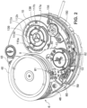
- la
figure 1 représente une vue en perspective d'un mouvement horloger comprenant des éléments d'un mécanisme d'affichage, - la
figure 2 représente une vue en perspective du mouvement horloger de lafigure 1 , des éléments de la partie supérieure ayant été retirés, - les
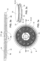
figures 3a, 3b et 3c représentent respectivement une vue de dessus, une vue en coupe selon l'axe AA et une vue en perspective d'un support d'information utilisé dans l'invention, - la
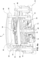
figure 4a représente une vue en coupe du magasin utilisé dans l'invention, un des supports d'information ayant été extrait dudit magasin, - la
figure 4b représente une vue en coupe du magasin utilisé dans l'invention, tous les supports d'information étant dans leur position inactive, - la
figure 5 représente une vue en perspective partielle des premiers moyens d'actionnement, - la
figure 6 représente une vue en perspective des premiers moyens de déplacement du support d'information et de leurs moyens de commande, - la
figure 7 représente une vue en coupe de la plate-forme sur laquelle est positionné un support d'information, - la
figure 8 représente une vue en perspective des moyens d'em brayage, - la
figure 9 représente une vue en perspective du bloc de commande et d'un premier dispositif de sécurité pour garantir le maintien en position des premiers moyens de déplacement, - les
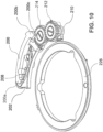
figures 10 et11 représentent respectivement une vue de dessus et de dessous d'un premier dispositif de sécurité pour garantir le maintien en position des premiers moyens de déplacement, - les
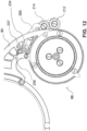
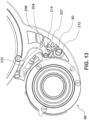
figures 12 et13 représentent respectivement ledit premier dispositif de sécurité lorsque le support d'information est en position inactive et lorsque le support d'information est en position active, - la
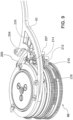
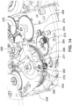
figure 14 représente une vue en perspective des moyens de déclenchement du mécanisme d'affichage, - la
figure 15 représente une vue en perspective d'un deuxième dispositif de sécurité de la mise en marche du mécanisme d'affichage, - les
figures 16 et17 représentent des vues du deuxième dispositif de sécurité de la mise en marche du mécanisme d'affichage, ledit mécanisme étant respectivement en position normale de fonctionnement et en position débrayée, - les
figures 18 et19 sont respectivement une vue en perspective et une vue de dessous d'un troisième dispositif de sécurité pour empêcher le déplacement du magasin lorsque les premiers moyens de déplacement ne sont plus disposés devant le magasin, - les
figures 20 et21 sont respectivement une vue en perspective et une vue de dessous du troisième dispositif de sécurité lorsque les premiers moyens de déplacement sont disposés devant le magasin, et - la
figure 22 est une vue en perspective du premier dispositif de sécurité en lien avec le levier du troisième dispositif de sécurité. - En référence aux
figures 1 et2 , il est représenté un mouvement horloger 1, comprenant un mécanisme d'affichage, ainsi qu'un affichage des minutes au moyen d'une aiguille rétrograde 2 et d'un arc 4 portant les graduations des minutes. - Le mécanisme d'affichage comprend un bâti sur lequel sont prévus un magasin 6 dans lequel sont stockés lesdits supports d'information 8 dans une position inactive de stockage, une plate-forme 10 agencée pour recevoir, de manière mobile en fonction de l'information horométrique à afficher, le support d'information 8 sélectionné dans une position active de fonctionnement, des premiers moyens de déplacement 12 du support d'information 8 sélectionné entre ladite position inactive de stockage dans le magasin 6 et ladite position active de fonctionnement sur la plate-forme 10, lesdits premiers moyens de déplacement 12 étant montés entre le magasin 6 et la plate-forme 10, et des moyens de commande 14 desdits premiers moyens de déplacement.
- Plus spécifiquement, en relation avec les
figures 3a, 3b, 3c , chaque support d'information 8 comprend un disque 16 portant une information horométrique. L'information horométrique peut être représentée sous la forme de graduations, de chiffres ou toute autre forme adéquate et peut correspondre par exemple à une heure selon un fuseau horaire, un quantième, une phase de lune, etc.... Des index permettant de repérer l'information horométrique à afficher sont prévus sur la glace du support d'information. Il est bien évident que la configuration inverse est possible, l'information horométrique étant représentée sous la forme d'un index représenté sur le disque 16, tel qu'une aiguille, des graduations étant prévues sur la glace du support d'information. Par ailleurs, le disque 16 peut se présenter sous la forme d'un disque plein ou d'un disque présentant une ouverture centrale pour former un anneau coaxial avec les autres supports d'information. Les supports d'information sous forme de plusieurs anneaux concentriques peuvent être utilisés par exemple pour l'affichage d'une grande date, les chiffres des unités et des dizaines étant positionnés sur deux anneaux différents. La plate-forme est alors agencée pour faire tourner simultanément les anneaux selon leur vitesse respective. Les anneaux peuvent également porter tout motif approprié de sorte que leurs entrainements respectifs par la plate-forme forment une animation. - Le disque portant l'information horométrique est solidaire d'un socle 17 comprenant sur son fond, dirigés vers l'extérieur, des premiers moyens de positionnement dudit disque 16 portant l'information horométrique sur la plate-forme 10. Lesdits premiers moyens de positionnement dudit disque 16 portant l'information horométrique sur la plate-forme 10 sont avantageusement constitués par une ouverture oblongue et par un orifice circulaire permettant respectivement de recevoir une goupille d'entrainement et une goupille pointeuse prévues sur la plate-forme 10 comme on le verra ci-après. Le socle 17 comprend également une rainure circulaire 18 agencée pour permettre la libre circulation des goupilles d'entrainement et pointeuse correspondant à un autre support d'information.
- Le socle 17 comprend également une denture périphérique extérieure 20 dont la fonction sera décrite ci-après.
- Le support d'information 8 comprend également une bague 22 à l'intérieur de laquelle le disque 16 portant l'information horométrique et son socle 17 sont disposés. L'ensemble est fermé au moyen d'une glace 24 sur laquelle sont représentés des index 26 permettant de repérer l'information horométrique à afficher.
- Le disque 16 portant l'information horométrique et son socle 17 sont montés libres en rotation à l'intérieur de la bague 22 autour d'un arbre 28 solidaire de la glace 24 au moyen d'un roulement à billes 25.
- La bague 22 comprend des logements constituant des deuxièmes moyens de positionnement 30 du support d'information 8 dans le magasin 6.
- La bague 22 comprend en outre des logements 32 agencés pour recevoir les premiers moyens de déplacement 12 du support d'information 8 sélectionné.
- Des découpes correspondantes sont prévues dans la glace 24.
- La bague 22 comprend également une découpe 34 agencée pour permettre le passage des moyens d'embrayage du disque 16 comme cela sera décrit ci-après.
- En référence aux
figures 4a et4b , le magasin 6 comprend un plateau 36 sur lequel sont superposés différents logements 38 agencés pour recevoir respectivement un support d'information 8. Sous le plateau 36 sont disposés des premiers moyens d'actionnement 40 agencés pour déplacer le magasin 6 de manière à présenter le support d'information 8 sélectionné au niveau des premiers moyens de déplacement. Lesdits premiers moyens d'actionnement 40 seront décrits ci-après. - Le mouvement comprend un châssis fixe 42 à l'intérieur duquel ledit magasin 6 est monté mobile en translation perpendiculairement au plan général du mouvement, de manière à pouvoir être déplacé et présenter le support d'information 8 sélectionné au niveau des premiers moyens de déplacement. Il est bien évident que le magasin peut être agencé de manière à être mobile selon un plan incliné par rapport au plan général du mouvement.
- Plus spécifiquement, le châssis fixe 42 comprend un pont inférieur 44, un pont intermédiaire (non représenté) et un pont supérieur 46 solidaires du bâti.
- Le châssis fixe 42 comprend également un premier ensemble de goupilles 48 montées entre le pont inférieur 44 et le pont intermédiaire, le long desquelles coulisse le plateau 36 du magasin 6 perpendiculairement au plan général du mouvement. Le châssis fixe 42 comprend également un second ensemble de goupilles 50 montées entre le pont inférieur 44 et le pont supérieur 46. Le plateau 36 du magasin 6 ainsi que les supports d'informations 8 sont agencés pour coulisser perpendiculairement au plan général du mouvement le long dudit second ensemble de goupilles 50, lesdites goupilles 50 étant notamment introduites dans les logements 30 prévus sur la bague 22 du support d'information 8. En outre, chaque goupille 50 est interrompue pour former un passage et permettre l'extraction du support d'information 8 sélectionné du magasin 6, comme le montre plus spécifiquement la
figure 4a . - En haut du magasin 6 se trouve un support d'information 52 monté mobile en rotation autour d'un axe 54 monté dans le logement supérieur du magasin 6. Un tel support d'information 52 est par exemple un disque comprenant des graduations permettant l'affichage de l'heure locale au moyen d'un index prévu sur la glace protégeant ledit disque. Ledit support d'information 52 se déplace en translation avec les autres supports d'information 8 stockés dans le magasin 6, mais reste dans son logement.
- Ledit support d'information 52 est solidaire d'une couronne 56 présentant une denture extérieure 58. Il est par ailleurs prévu sur le châssis fixe 42 un arbre 59 (visible sur les
figures 1 et2 ) monté pivotant et comprenant à son extrémité supérieure un pignon 60 engrenant avec la denture extérieure 58 de la couronne 56, et à l'extrémité inférieure un premier élément d'un ensemble de renvois reliés cinématiquement à une roue des heures permettant de faire tourner le support d'information 52 à la vitesse des heures. Le pignon 60 est suffisamment long pour que la denture extérieure 58 de la couronne 56 reste engrenée avec ledit pignon 60 lorsque le support d'information 52 coulisse avec le magasin 6. - En référence à la
figure 5 , les premiers moyens d'actionnement 40 agencés pour déplacer le magasin 6 comprennent un bras de sélection 62, accessible à un utilisateur et solidaire d'une platine 240 montée pivotante sur le châssis fixe 42, de sorte que le déplacement angulaire du bras de sélection 62 entraine le déplacement en translation du plateau 36 du magasin 6. A cet effet, il est prévu un train démultiplicateur comprenant un pignon 64 monté pivotant sur la platine 240. Ledit pignon 64 engrène avec une denture intérieure 66 d'une roue fixe 68 prévue sur le bâti et est également solidaire d'une roue dentée 70 coopérant avec une roue dentée 72 solidaire d'un écrou 74 présentant un filetage intérieur 75. Par ailleurs, il est prévu, solidaire du plateau 36, une vis 76 présentant un filetage extérieur agencé pour coopérer avec le filetage intérieur 75 de l'écrou 74. - Ainsi, un déplacement angulaire du bras de sélection 62, entraine un déplacement angulaire du pignon 64 qui, coopérant avec la denture 66, pivote sur son axe, entrainant en rotation la roue dentée 70, entrainant elle-même en rotation la roue dentée 72 et l'écrou 74. La rotation de l'écrou 74 entraine le déplacement en translation de la vis 76, et donc du plateau 36 et du magasin 6.
- En référence aux
figures 2 et5 , les premiers moyens de déplacement 12 du support d'information 8 sélectionné comprennent un bras 80 monté pivotant entre le magasin 6 et la plate-forme 10, ledit bras 80 présentant des moyens de préhension du support d'information 8 sélectionné agencés pour extraire le support d'information sélectionné de son logement 38 dans le magasin 6. Plus spécifiquement, le bras 80 présente la forme d'une fourche à deux branches, dont les extrémités présentent des excroissances 81 agencées pour se loger dans les logements 32 prévus sur la bague 22 du support d'information 8. Les branches du bras 80 sont dimensionnées pour se positionner autour de la bague 22 du support d'information 8 sélectionné. De manière avantageuse, un ou deux des logements 30 utilisés pour positionner le support d'information 8 dans le magasin 6 au moyen des goupilles 50 peuvent être utilisés également comme logements 32 pour loger une ou deux des excroissances 81 du bras 80. - Le bras 80 est motorisé au moyen d'un barillet indépendant 234 (cf.
figure 14 ), et enclenché au moyen d'un poussoir 248 (cf.figures 1 et14 ), ou tout autre moyen adéquat. Au centre du bras 80 se trouve une réserve de cycle 82 agencée pour indiquer la réserve du barillet du bras 80. Un cycle correspond à la sortie d'un support d'information 8 et son retour dans le magasin 6. L'affichage de la réserve de cycle 82 est trainant. - Le bras 80 est monté solidaire sur une roue d'actionnement dentée 84, l'ensemble étant monté libre en rotation autour d'un axe 86 monté sur le bâti, ledit axe 86 étant l'axe autour duquel pivote un bloc de commande centralisée 88. Ce bloc de commande centralisée 88 comprend, reliées solidairement, notamment une roue de commande du bras dans le sens horaire 90, une roue de commande du bras dans le sens anti-horaire 92, et une roue d'alimentation 94 reliée cinématiquement au barillet indépendant de motorisation du bras 80 par l'intermédiaire d'un pignon 95 visible sur la
figure 1 . - Les roues de commande du bras dans le sens horaire 90 et dans le sens anti-horaire 92 comprennent respectivement un secteur denté de 60° disposé de sorte que le déplacement du bras 80 corresponde à une rotation desdites roues de commande de 60°.
- Il est également prévu un ensemble de pignons inverseurs permettant de faire tourner la roue d'actionnement 84 du bras 80 dans le sens horaire ou anti-horaire. Cet ensemble comprend un ensemble de deux pignons solidaires monté fous sur le bâti, à savoir un pignon 96 agencé pour coopérer avec le secteur denté de la roue de commande du bras dans le sens horaire 90 et un pignon 98 agencée pour coopérer avec la roue d'actionnement 84 du bras 80. Il est également prévu un pignon 100 monté fou sur le bâti et agencé pour coopérer d'une part avec le secteur denté de la roue de commande du bras dans le sens anti-horaire 92 et d'autre part avec un autre pignon 102 monté fou sur le bâti, lui-même étant agencé pour coopérer avec la roue d'actionnement 84 du bras 80. Les secteurs dentés des roues de commande du bras dans le sens horaire 90 et anti-horaire 92 sont disposés de sorte que lorsque l'un des secteurs dentés arrive devant le pignon correspondant de l'ensemble inverseur, l'autre secteur denté ne coopère pas avec le pignon correspondant de l'ensemble inverseur.
- Il est prévu, sur l'axe des pignons 96-98 et sur l'axe du pignon 100, un plat 97 agencé pour coopérer respectivement avec un levier de positionnement 101 (visible sur la
figure 1 ) monté pivotant sur le bâti. Le levier de positionnement présente un bord latéral plat agencé pour coopérer avec le plat 97 afin de faire pivoter les pignons 96-98 et 100 pour les repositionner parfaitement lorsque le cycle est terminé. - Le bloc de commande centralisée 88 est régulé au moyen d'un mécanisme de régulation 104 du type régulateur à échappement (visible sur la
figure 1 ) comprenant un train de renvois dont le premier élément engrène avec la roue d'alimentation 94, et le dernier élément engrène avec une roue d'échappement 106 coopérant avec une ancre. Un tel mécanisme est connu de l'homme du métier et ne nécessite pas plus de détails. - Le bloc de commande centralisée 88 comprend également une roue de sécurité 108 comprenant deux dents agissant comme une came pour actionner un sautoir (non représenté) afin de libérer toute pression sur le bras 80 lors de son déplacement et pour le repositionner en appui sur le bras 80 afin de garantir le bon positionnement du bras 80 lorsque le support d'information 8 est en position active ou inactive.
- Selon une autre variante de réalisation représentée sur les
figures 9 à 13 , il est prévu un premier dispositif de sécurité permettant de garantir le maintien en position des premiers moyens de déplacement 12, et plus spécifiquement du bras 80, lorsque le support d'information 8 est en position active ou inactive. A cet effet, le dispositif de sécurité comprend un levier de sécurité 200 agencé pour évoluer entre une position armée selon laquelle il exerce une pression sur le bras 80 pour le maintenir en position une fois que ledit bras 80 a placé le support d'information 8 en position active ou inactive et une position désarmée selon laquelle il laisse libre le bras 80 de se déplacer pour placer le support d'information 8 en position active ou inactive. Le dispositif de sécurité comprend également des moyens d'armage dudit levier de sécurité 200 agencés pour le positionner dans sa position armée ainsi que des moyens de désarmage dudit levier de sécurité agencés pour le positionner dans sa position désarmée. Plus spécifiquement en référence à lafigure 10 , le dispositif de sécurité comprend un pont 202 sur un côté duquel est monté pivotant le levier de sécurité 200. Celui-ci comporte à chacune de ses extrémités un nez 200a, 200b dont la forme est choisie pour permettre le meilleur contact possible avec une goupille 204, 206 respectivement, prévue sur le bras 80 (cf.figures 9 ,12 et13 ). De plus, le levier de sécurité comprend une branche supplémentaire 200c, latérale, présentant la forme d'un râteau dont la fonction sera décrite ci-après. Le levier de sécurité 200 est également muni d'un sautoir 208. - Les moyens d'armage du levier de sécurité 200 comprennent un pignon d'armage 210 muni d'un secteur denté monté pivotant sur le pont 202 du côté opposé au levier de sécurité 200, et deux pignons 212, 214 montés pivotant sur le pont du même côté que le levier de sécurité, le premier pignon 212 étant solidaire du pignon d'armage 210 et le deuxième pignon 214 coopérant d'une part avec le premier pignon 212 et d'autre part avec le râteau de la une branche supplémentaire 200c du levier de sécurité 200. Comme le montre la
figure 11 , les moyens d'armage comprennent également une came d'armage 216 montée pivotante sur le pont 202 du même coté que le pignon d'armage 210, ladite came d'armage 216 étant solidaire du deuxième pignon 214. - En référence à la
figure 11 , les moyens de désarmage comprennent une bascule de désarmage 218 montée pivotante sur le pont 202 du même côté que le pignon d'armage 210. La bascule de désarmage 218 comprend un doigt de désarmage 220 dont la fonction sera décrite ci-après. La bascule de désarmage 218 comprend également un bec 222 agencé pour coopérer avec la came d'armage 216 et la bloquer. La bascule de désarmage 218 est munie d'un sautoir 224. - Par ailleurs, comme le montre la
figure 10 , le bloc de commande centralisée 88 comprend une roue de sécurité 226 comprenant des secteurs dentés 227, 228 agencés pour coopérer avec le secteur denté du pignon d'armage 210 et deux dents 229, 230 agencées pour coopérer avec le doigt de désarmage 220 de la bascule de désarmage 218. Les secteurs dentés 227, 228 et les dents 229, 230 sont répartis sur la roue de sécurité 226 de manière à déclencher le dispositif de sécurité aux moments adéquats. - Le fonctionnement du dispositif de sécurité est le suivant : en référence à la
figure 12 , lorsque le bras 80 est placé devant le magasin 6, le support d'information étant en position inactive, le levier de sécurité 200 est en position armée, son nez 200a appuyant sur la goupille 204 de manière à maintenir le bras 80 dans cette position. La came d'armage 216 est bloquée par le bec 222, de sorte tout le mécanisme d'armage est bloqué, et donc également le râteau 200c. De ce fait, le levier de sécurité 200 est immobilisé contre le bras 80. Lorsque l'utilisateur a lancé un cycle, la roue de sécurité 226 tourne de sorte qu'une des dents 229, 230 vient coopérer avec le doit de désarmage 220 de manière à soulever la bascule de désarmage 218 et de ce fait libérer la came d'armage 216. Le mécanisme d'armage n'est alors plus bloqué de sorte que le râteau 200c, et donc le levier de sécurité 200 tombe dans sa position désarmée. Le bras 80 peut alors se dégager et pivoter. Lorsque le bras 80 se positionne devant la plate-forme 10 pour placer le support d'information en position active, la roue de sécurité 226 tourne de sorte que l'un des secteurs dentés 227, 228 coopère avec le pignon d'armage 210 pour le faire pivoter. La rotation du pignon d'armage 210 entraine la rotation du premier pignon 212, et donc du deuxième pignon 214, et ainsi de la came d'armage 216 d'une part et du râteau 200c du levier de sécurité 200 d'autre part. Le levier de sécurité 200 est remonté de manière à ramener son nez 200b contre la goupille 206 et appuyer sur le levier de sécurité 200 pour le maintenir dans sa position, comme le montre lafigure 13 . En même temps, la came d'armage 216 pivote jusqu'à venir coopérer avec le bec 222 de la bascule de désarmage 218 et le bloquer, de sorte que le dispositif de sécurité est armé et bloqué. Puis le même cycle de désarmage et armage reprend. - Les autres éléments du bloc de commande centralisée 88 seront décrits ultérieurement.
- En référence aux
figures 2 et7 , la plate-forme 10 comprend autant de couronnes 112 concentriques que d'informations horométriques à afficher sur la plate-forme 10, chacune desdites couronnes 112 étant agencée pour recevoir un support d'information 8 associé. De plus, chaque couronne 112 est toujours mobile en rotation à une vitesse choisie en fonction de l'information horométrique affichée sur le support d'information 8 associé. Pour cela, chaque couronne 112 est solidaire d'un plateau annulaire 114 lui-même solidaire d'une roue d'entrainement reliée cinématiquement au mécanisme correspondant à l'information sélectionné et permettant d'entrainer le plateau annulaire 114 et donc la couronne 112 à la vitesse appropriée. Par exemple, la couronne 112a est la couronne utilisée pour porter le support d'information affichant le quantième, et est solidaire du plateau annulaire 114a lui-même solidaire d'une couronne d'entrainement 116 reliée cinématiquement à la roue de quantième du mouvement. La couronne 112b est la couronne utilisée pour porter le support d'information affichant l'heure selon un fuseau horaire différente de l'heure locale, et est solidaire du plateau annulaire 114b lui-même solidaire d'une couronne d'entrainement 118 reliée cinématiquement à la roue des heures selon les fuseaux horaires. Un mécanisme de correction de cette heure peut être prévu et comprend notamment une couronne correctrice 120. - De plus, chaque couronne 112 comprend des troisièmes moyens de positionnement agencés pour coopérer avec les premiers moyens de positionnement du disque portant l'information horométrique, les premiers et troisièmes moyens de positionnement étant agencés pour que le disque 16 portant l'information horométrique se positionne sur la couronne 112 associée afin d'afficher de manière juste l'information horométrique associée.
- Comme cela a été vu ci-dessus, lesdits troisièmes moyens de positionnement prévus sur les couronnes 112a, 112b sont avantageusement constitués par une goupille d'entrainement 115a, 115b agencées pour coopérer avec l'ouverture oblongue prévue sur le socle 17 du disque 16 et par une goupille pointeuse 117a, 117b agencées pour coopérer avec l'orifice circulaire prévu sur le socle 17 du disque 16.
- Les troisièmes moyens de positionnement prévus sur les couronnes 112a, 112b sont mobiles en translation entre une position basse permettant la mise en place du support d'information 8 sélectionné sur la plate-forme 10 et une position haute permettant la coopération entre le support d'information 8 sélectionné et sa couronne associée 112a, 112b.
- Plus précisément, il est prévu entre chaque couronne 112a, 112b et son plateau annulaire associé 114a, 114b, un anneau intermédiaire 119a, 119b solidaire en rotation de la couronne 112a, 112b et du plateau annulaire 114a, 114b associés, mais libre de se déplacer en translation perpendiculairement au plan général du mouvement entre ladite couronne 112a, 112b et ledit plateau annulaire 114a, 114b associés.
- De même, les goupilles d'entrainement 115a, 115b et les goupilles pointeuses 117a, 117b sont libres de se déplacer en translation perpendiculairement au plan général du mouvement entre ladite couronne 112a, 112b et ledit plateau annulaire 114a, 114b associés entre ladite position basse et ladite position haute.
- Les goupilles d'entrainement 115a, 115b et les goupilles pointeuses 117a, 117b sont montées traversantes dans leur anneau intermédiaire 119a, 119b respectif et comprennent un rebord annulaire permettant de rendre les rendre solidaires de l'anneau intermédiaire associé 119a, 119b.
- Ces différentes couronnes ainsi que les plateaux annulaires et les anneaux intermédiaires associés sont montés mobiles en rotation autour d'un arbre 122 solidaire du bâti et d'un arbre 124 coaxial, lui-même mobile en translation perpendiculairement au plan général du mouvement.
- L'arbre 124 porte solidairement un plateau central 138 qui comporte un épaulement supérieur 139 sur lequel se positionne l'arbre 28 du disque 16, son roulement à billes 25 se positionnant autour dudit épaulement supérieur 139. Les goupilles d'entrainement 115a, 115b et les goupilles pointeuses 117a, 117b s'engagent soit dans l'ouverture oblongue et l'orifice circulaire prévus sur le socle 17 du disque 16 associé, soit dans la rainure circulaire 18 du disque qui n'est pas associé, dans laquelle lesdites goupilles d'entrainement 115a, 115b et les goupilles pointeuses 117a, 117b peuvent librement circuler.
- Le plateau central 138 s'étend au-dessus du pourtour intérieur de l'anneau intermédiaire 119b. Le pourtour extérieur de l'anneau intermédiaire 119b s'étend au-dessus d'un épaulement prévu sur le pourtour intérieur de l'anneau intermédiaire 119a. Les plateaux 119a, 119b et 138 sont libres les uns par rapport aux autres. Ainsi lorsque l'arbre 124 se déplace en translation vers le bas, le plateau central 138 appuie sur l'anneau intermédiaire 119b qui appuie sur l'anneau 119a de sorte que les goupilles d'entrainement 115a, 115b et les goupilles pointeuses 117a, 117b descendent en position basse.
- Un ressort-lame 121 est prévu respectivement pour faire remonter chacun des anneaux intermédiaires 119a, 119b lorsque le plateau central 138 n'exerce plus de pression, de sorte que les goupilles d'entrainement 115a, 115b et les goupilles pointeuses 117a, 117b remontent en position haute.
- Le déplacement en translation, perpendiculairement au plan général du mouvement, des goupilles d'entrainement 115a, 115b et des goupilles pointeuses 117a, 117b entre leur position basse et leur position haute est réalisé par le biais des deuxièmes moyens de déplacement prévus sur la plate-forme 10.
- Lesdits deuxièmes moyens de déplacement 126 comprennent les anneaux intermédiaires 119a, 119b, l'arbre 124 et son plateau central 138, ainsi qu'une couronne dentée 128 agencée pour coopérer, par l'intermédiaire des renvois nécessaires, avec une roue de commande 130 de la plate-forme 10 solidaire des autres roues de commande du bloc de commande centralisée 88. La roue de commande 130 de la plate-forme 10 comprend quatre secteurs dentés de 30° répartis autour de ladite roue de commande 130 de la plate-forme 10 de sorte qu'une rotation de 30° de la roue de commande 130 de la plate-forme 10 entraine une montée en position haute ou une descente en position basse des goupilles d'entrainement 115a, 115b et des goupilles pointeuses 117a, 117b lorsque la couronne dentée 128 est reliée cinématiquement aux secteurs dentés de la roue de commande 130 de la plate-forme 10.
- La couronne dentée 128 est solidaire d'un tube 132 monté mobile en rotation autour d'un arbre 134 fixé sur le bâti et coaxial à l'arbre 122 et à l'arbre 124 autour duquel il est monté. Le tube 132 comprend sur son pourtour intérieur une came hélicoïdale 136 agencée pour coopérer avec une came hélicoïdale prévue sur le pourtour extérieur de l'arbre 124. Ainsi, une rotation de la couronne dentée 128 entraine un déplacement en translation, perpendiculairement au plan général du mouvement aussi bien vers le haut que vers le bas, de l'arbre 124 qui est monté coulissant sur l'arbre 134, et donc un déplacement en translation, perpendiculairement au plan général du mouvement, du plateau central 138.
- Afin d'aider le support d'information 8 sélectionné à se positionner sur la plate-forme 10, le mécanisme comprend en outre des moyens d'embrayage agencés pour faire pivoter le support d'information 8 sélectionné positionné sur la plate-forme 10 jusqu'à ce que ledit support d'information sélectionné 8 coopère avec la couronne associée 112a, 112b.
- En référence à la
figure 8 , lesdits moyens d'embrayage comprennent un châssis d'embrayage 150 solidaire du bâti du mouvement et une bascule 152 montée pivotante sur le châssis d'embrayage 150 autour d'un axe 154. Sur la bascule 152 sont montés pivotants un pignon d'embrayage 156 ainsi qu'un premier élément d'un train de renvois relié au pignon d'embrayage 156 au moyen d'un système à friction 158. Le pignon d'embrayage 156 est agencé pour s'engager dans la découpe 34 prévue sur la bague 22 du support d'information 8 et venir engrener avec la denture périphérique extérieure 20 prévue sur le socle du disque 16. La bascule 152 permet au pignon d'embrayage 156 de basculer légèrement et s'écarter pour permettre le positionnement du support d'information 8 sélectionné sur la plate-forme 10. - Un sautoir 160 prévu sur le châssis d'embrayage 150 coopère avec une goupille 162 prévue sur la bascule 152 afin d'assurer le positionnement du pignon d'embrayage 156.
- Le train de renvoi comprend également la roue 164, montée sur le châssis d'embrayage 150 et reliée cinématiquement aux deuxièmes moyens d'actionnement des moyens d'embrayage. Lesdits deuxièmes moyens d'actionnement des moyens d'embrayage sont avantageusement constitués par une roue de commande d'embrayage 166 solidaire des autres roues de commande du bloc de commande centralisée 88. La roue de commande d'embrayage 166 comprend un secteur denté de 120° de sorte qu'une rotation de 120° de la roue de commande d'embrayage 166 entraine une rotation du disque 16 de 400° au maximum, jusqu'à ce que les goupilles d'entrainement 115a, 115b et les goupilles pointeuses 117a, 117b soient correctement positionnées dans le disque associé pour que celui-ci coopère avec sa couronne 112a, 112b associée.
- Selon une variante non représentée, le disque peut comprendre sur sa face inférieure des picots représentatifs d'une mélodie et la plate-forme peut porter un peigne agencé pour coopérer avec les picots afin de constituer une mélodie, de la manière similaire à une boite à musique. Différents disques peuvent être prévus pour proposer différentes mélodies. Dans ce cas, la plate-forme est adaptée pour que le disque soit entrainé par les moyens d'embrayage uniquement.
- Les différents secteurs dentés des roues de commande sont agencés les uns par rapport aux autres en fonction de l'évolution du cycle de sortie et de retour du support d'information 8 sélectionné du magasin.
- Le déroulement d'un tel cycle est le suivant : l'utilisateur actionne le bras de sélection 62 afin de déplacer en translation le magasin 6 et d'amener le support d'information 8 sélectionné au niveau du bras 80 de sorte que ses excroissances 81 s'engagent dans les logements 32 prévus sur la bague 22 du support d'information. Si la réserve de cycle est suffisante, le cycle démarre lorsque l'utilisateur active des moyens de déclenchement du mécanisme tel que le poussoir 248 qui enclenche le déroulement du barillet 234 et donc l'alimentation en énergie du bloc de commande centralisée 88 par la roue d'alimentation 94.
- Selon un mode de réalisation préféré des moyens de déclenchement du mécanisme d'affichage représentés sur la
figure 14 , lesdits moyens de déclenchement du mécanisme d'affichage de l'invention comprennent le poussoir 248 solidaire d'une bascule 260 dont un bras comprend un premier bec 262, un levier de blocage 264 comprenant un nez 266 agencé pour coopérer avec le bec 262, et une came de blocage 268 du barillet 234 agencée pour coopérer avec le levier de blocage 264. Lorsque l'utilisateur appuie sur le poussoir 248, le bec 262 coopère avec le nez 266 du levier de blocage 264 qui se soulève de sorte que la came de blocage 268 est libérée et autorise la rotation du barillet 234. - Les moyens de déclenchement du mécanisme d'affichage sont également agencés pour coopérer avec une réserve de marche 269. A cet effet, le bras de la bascule 260 comprend un deuxième bec 270 agencé pour coopérer avec une goupille 271 prévue à l'extrémité d'un bras d'une bascule 272 de réserve de marche. Un autre bras 274 de ladite bascule 272 de réserve de marche coopère avec une came 276 de réserve de marche. Lorsque la réserve de marche est épuisée, la came 276 de réserve de marche est positionnée de sorte que la bascule 272 de réserve de marche pivote pour positionner sa goupille 271 sur la course du deuxième bec 270. Ainsi, lorsque l'utilisateur appuie sur le poussoir 248, le deuxième bec 270 entre au contact de la goupille 271 ce qui permet d'empêcher le déplacement du premier bec 262 jusqu'au levier de blocage 264 et ainsi de débrayer les moyens de déclenchement du mécanisme.
- De plus, la bascule 272 de réserve de marche est solidaire d'une deuxième goupille 254 dont la fonction sera décrite ci-après.
- En référence aux
figures 15 à 17 , il est prévu par ailleurs un deuxième dispositif de sécurité de la mise en marche du mécanisme d'affichage de l'invention agencé pour permettre d'une part audit mécanisme d'occuper une position normale de fonctionnement lorsque le magasin 6 se repositionne correctement après son déplacement et pour permettre d'autre part auxdits moyens de déclenchement d'occuper leur position débrayée empêchant tout mouvement des premiers moyens de déplacement 12, et donc du bras 80, lorsque le magasin 6 n'est pas positionné correctement, et plus spécialement lorsqu'il ne se repositionne pas correctement après son déplacement. En référence auxfigures 15 et16 , ce deuxième dispositif de sécurité de la mise en marche du mécanisme d'affichage comprend autant de positionneurs que de supports d'information 8, à savoir ici trois positionneurs 242 montés sur la platine 240. Chaque positionneur 242 présente une forme de secteur circulaire, le rebord périphérique extérieur comportant une encoche 243 dont la fonction sera décrite ci-après. Chaque positionneur 242 comprend en son centre une ouverture oblongue 244 à travers laquelle sont introduites les vis de fixation 245 du positionneur 242. Cela permet de régler de manière précise la position de chaque positionneur 242. Le dispositif de sécurité de la mise en marche du mécanisme d'affichage comprend également un premier levier 246 monté pivotant sur le bâti et comprenant un bec de positionnement 247 correspondant aux encoches 243. Le levier 246 est agencé d'une part pour que son bec de positionnement 247 soit engagé dans l'une des encoches 243 lorsque le magasin 6 occupe sa position normale de fonctionnement après son déplacement et d'autre part pour coopérer avec les moyens de déclenchement du mécanisme d'affichage, et plus spécifiquement débrayer le poussoir 248, lorsque le magasin 6 ne se repositionne pas correctement après son déplacement et que le bec de positionnement 247 n'est plus engagé dans l'une des encoches 243, tel que cela est représenté sur lafigure 17 . A cet effet, le dispositif de sécurité de la mise en marche du mécanisme d'affichage comprend également un second levier 250 monté pivotant sur le bâti et comprenant un premier bras 251 portant une première goupille 252 agencée pour coopérer avec le premier levier 246 et un deuxième bras 253 agencé pour appuyer sur la deuxième goupille 254 solidaire de la bascule 272 de réserve de marche lorsque le bec de positionnement 247 n'est pas engagé dans l'une des encoches 243. Ainsi, lorsque le bec de positionnement 247 n'est pas engagé dans l'une des encoches 243, le premier levier 246 fait basculer le deuxième levier 250 en poussant la première goupille 252, de sorte que son deuxième bras 253 déplace la deuxième goupille 254 et donc la bascule 272 de réserve de marche. Cette dernière pivote et se trouve alors dans la même position que lorsque la réserve de marche est épuisée, telle que décrite ci-dessus. Ainsi, lorsque le bec de positionnement 247 n'est pas engagé dans l'une des encoches 243, le barillet 234 reste bloqué et donc le bras 80 ne peut se déplacer. Le cycle est arrêté jusqu'à ce que l'utilisateur actionne le bras de sélection 62 de manière à positionner correctement le magasin 6 pour que le bec de positionnement 247 s'engage dans l'une des encoches 243. La deuxième goupille 254 et donc la bascule 272 de réserve de marche reviennent en position pour autoriser la libération du barillet 234 par actionnement du poussoir 248. - L'agencement des différents secteurs dentés des roues de commande du bloc de commande centralisée 88 est tel que les deuxièmes moyens de déplacement 126, et notamment la couronne dentée 128, sont tout d'abord actionnés de manière à faire descendre l'arbre 124 et donc les goupilles d'entrainement 115a, 115b et les goupilles pointeuses 117a, 117b en position basse.
- L'agencement des différents secteurs dentés des roues de commande du bloc de commande centralisée 88 est tel qu'est ensuite actionné, au moyen de la roue de commande du bras dans le sens horaire 90 coopérant avec le pignon 96, le bras 80 dans le sens horaire, afin d'amener le support d'information 8 sélectionné au-dessus de la plate-forme 10, les goupilles d'entrainement 115a, 115b et les goupilles pointeuses 117a, 117b étant rentrées en position basse.
- Dans une autre variante de réalisation de l'invention, il peut être prévu un troisième dispositif de sécurité agencé pour empêcher le déplacement du magasin 6 en cas d'actionnement du bras de sélection lorsque le bras 80 n'est plus positionné devant le magasin 6. Dans cette variante, en référence aux
figures 18 à 22 , le bras de sélection correspondant au bras de sélection 62 représenté sur lafigure 5 est désormais référencé 277 et est ici solidaire d'une bague 278, l'ensemble étant monté pivotant sur le bâti, sous la platine 240. Les moyens d'actionnement 40 comprenant le pignon 64, la denture intérieure 66, la roue dentée 70 et la roue dentée 72 solidaire de l'écrou 74 restent identiques à ce qui a été décrit ci-dessus. - Ledit troisième dispositif de sécurité comprend un levier 280 monté pivotant sur le bâti et présentant deux branches 280a, 280b solidaires, et une came 281 montée pivotante sur la platine 240. Le levier 280 est positionné de sorte que sa branche 280b peut coopérer avec une goupille 207 (cf.
figures 9 ,12 ,13 , et22 ) prévue sur le bras 80 lorsque ce dernier est positionné devant le magasin 6. La came 281 comprend une partie 282 globalement circulaire, excentrée par rapport à l'axe de l'écrou 74, et présentant un rebord 283 agencé pour coopérer avec une goupille 284 prévue à l'extrémité de la branche 280a du levier 280. La came 281 comprend également un bras 286 sensiblement concentrique à la partie circulaire 282 et présentant une ouverture oblongue 288 dont la fonction sera décrite ci-après. Le troisième dispositif de sécurité comprend également deux pinces 290 et 292, la pince 292 étant solidaire d'un arbre 294 (cf.figure 20 ) monté pivotant à travers la platine 240 et la pince 290 étant reliée à la pince 292 par un doigt 293 prévu sur la pince 292 et engagé dans une encoche 295 de la pince 290. L'arbre 294 porte un bras 296 sur lequel est prévue une goupille 298, agencée pour circuler dans l'ouverture oblongue 288 de la came 281. Le troisième dispositif de sécurité comprend également la bague 278 dont le pourtour présente deux encoches 302 agencées pour recevoir respectivement une pince 290, 292. Ainsi, lorsque le bras 80 se déplace entre le magasin 6 et la plate-forme 10, sa goupille 207 s'écarte et libère la branche 280b du levier 280. Le levier 280 pivote sous l'action de son ressort de rappel 304 de sorte que sa goupille 284 appuie sur le rebord 283 de la came 281 pour la faire pivoter. Le pivotement de la came 281 entraine le déplacement de la goupille 298 dans l'ouverture oblongue 288 de manière à faire pivoter l'arbre 294 et donc la pince 292. La pince 292 s'ouvre et se dégage de son encoche 302. L'autre pince 290 suit le même mouvement et se dégage de son encoche de sorte que la bague 278 est désolidarisée de la platine 240 et débrayée, comme le montrent lesfigures 18 et19 . De ce fait, si le bras de sélection 277 est déplacé angulairement, la bague 278 tourne devant les pinces 290 et 292 sans pouvoir coopérer avec elles. La platine 240 n'étant pas entrainée en rotation, les premiers moyens d'actionnement pour déplacer le magasin 6 ne sont alors pas actionnés. Le magasin 6 ne peut donc pas être déplacé, et cela tant que le bras 80 n'est pas repositionné devant le magasin 6. Quand le bras 80 revient devant le magasin 6, sa goupille 207 appuie de nouveau sur la branche 280b du levier 280 de manière à déplacer la came 281, et donc la goupille 298, ce qui entraine la rotation de l'arbre 294 et la fermeture des pinces 290 et 292 dans leurs encoches 302 prévues sur la bague 278, comme le montrent lesfigures 20 et21 . La bague 278 est donc de nouveau reliée solidairement à la platine 240 de sorte que l'actionnement du bras de sélection 277 entraine le déplacement du magasin 6 comme décrit ci-dessus. - L'agencement des différents secteurs dentés des roues de commande du bloc de commande centralisée 88 est tel que sont ensuite de nouveau actionnés les deuxièmes moyens de déplacement 126, et notamment la couronne dentée 128, de manière à faire monter l'arbre 124 et donc les goupilles d'entrainement 115a, 115b et les goupilles pointeuses 117a, 117b en position haute.
- L'agencement des différents secteurs dentés des roues de commande du bloc de commande centralisée 88 est tel qu'est ensuite actionné le pignon d'embrayage 156 engrenant avec le disque 16 jusqu'à ce que la goupille d'entrainement associée 115a, 115b et la goupille pointeuse associée 117a, 117b se positionnent correctement dans le socle 17 du disque 16, ce qui entraine le débrayage du pignon d'embrayage 156. Le cycle est alors arrêté en arrêtant la rotation du bloc de commande centralisée 88.
- Le disque 16 est désormais rendu solidaire de sa couronne 112a, 112b associée, et tourne sur la plate-forme à la vitesse adéquate en fonction de l'information affichée. La bague 22 maintenue par le bras 80 positionné devant la plate-forme 10, reste fixe, de même que la glace 24, ce qui permet de lire l'information au moyen des index 26 prévus sur la glace 24. Du fait que les couronnes 112a, 112b tournent en permanence, même lorsque leur disque 16 associé n'est pas positionné sur la plate-forme 10, la mémoire de l'information est conservée et le disque associé 16 se met automatiquement à jour lorsqu'il est mis en place sur la plate-forme 10.
- Lorsque l'utilisateur souhaite de nouveau modifier le support d'information en place sur la plate-forme 10, il actionne le poussoir pour relancer le barillet et la rotation du bloc de commande centralisée 88.
- L'agencement des différents secteurs dentés des roues de commande du bloc de commande centralisée 88 est tel que sont de nouveau actionnés les deuxièmes moyens de déplacement 126, et notamment la couronne dentée 128, de manière à faire descendre l'arbre 124 et donc les goupilles d'entrainement 115a, 115b et les goupilles pointeuses 117a, 117b en position basse.
- L'agencement des différents secteurs dentés des roues de commande du bloc de commande centralisée 88 est tel qu'est ensuite actionné, au moyen de la roue de commande du bras dans le sens anti-horaire 92 coopérant avec le pignon 100, le bras 80 dans le sens anti-horaire, afin de ramener le support d'information 8 sélectionné dans le magasin 6.
- L'agencement des différents secteurs dentés des roues de commande du bloc de commande centralisée 88 est tel que sont ensuite de nouveau actionnés les deuxièmes moyens de déplacement 126, et notamment la couronne dentée 128, de manière à faire monter l'arbre 124 et donc les goupilles d'entrainement 115a, 115b et les goupilles pointeuses 117a, 117b en position haute. Puis le cycle s'arrête. Comme le montre la
figure 4b , le bras 80 reste devant le magasin 6 et sert de butée pour éviter que le support d'information 8 placé à son niveau ne sorte du magasin 6 de manière intempestive. - Ainsi, l'utilisateur peut modifier comme il le souhaite, le support d'information 8 positionné sur la plate-forme de manière à pouvoir afficher, à une même place, différentes informations horométriques.
- Il est bien évident que la présente invention n'est pas limitée à la réalisation décrite. Notamment le nombre de couronnes peut varier.
- Par ailleurs, les différents dispositifs de sécurité ainsi que les autres dispositifs telle que la plate-forme ou le bloc de commande peuvent être utilisés indépendamment dans d'autres mécanismes que le mécanisme d'affichage de l'invention. Par exemple, le premier dispositif de sécurité peut être utilisé pour sécuriser la position d'un bras de chronographe. Le deuxième dispositif de sécurité peut être utilisé dans un mécanisme de sonnerie pour empêcher le lancement de la sonnerie si le mécanisme est sur sa position de mise à l'heure. Le troisième dispositif de sécurité peut être utilisé dans un mécanisme de sonnerie pour empêcher la mise à l'heure si l'utilisateur a déjà lancé la sonnerie.
Claims (5)
- Ensemble de commande pour pièce d'horlogerie comportant un arbre (86), un bras (80) monté solidaire sur une roue d'actionnement dentée (84) montée libre en rotation autour dudit arbre (86) et un bloc de commande centralisée (88) pivotant autour de l'arbre (86), le bloc de commande centralisée (88) étant configuré pour actionner ledit bras (80) dans un sens horaire et dans un sens anti-horaire, ledit bloc de commande centralisée (88) comprenant:- une première roue de commande (90) du bras (80) dans le sens horaire ;- une deuxième roue de commande (92) du bras (80) dans le sens anti-horaire ; et- une roue d'alimentation (94) reliée cinématiquement à un barillet indépendant de motorisation du bras (80) ;la première roue de commande (90) du bras (80) dans le sens horaire, la deuxième roue de commande (92) du bras (80) dans le sens anti-horaire et la roue d'alimentation (94) étant reliées solidairement.
- Ensemble de commande d'une pièce d'horlogerie selon la revendication 1, caractérisé en ce que la première roue de commande (90) du bras (80) dans le sens horaire et la deuxième roue de commande (92) du bras (80) dans le sens anti-horaire comprennent respectivement un secteur denté de 60° disposé de sorte que le déplacement du bras (80) corresponde à une rotation de 60° de ladite première roue de commande (90) du bras (80) dans le sens horaire et de ladite deuxième roue de commande (92) du bras (80) dans le sens anti-horaire.
- Ensemble de commande d'une pièce d'horlogerie selon la revendication 2, caractérisé en ce qu'il comprend en outre un ensemble de pignons inverseurs permettant de faire tourner la roue d'actionnement (84) du bras (80) dans le sens horaire ou anti-horaire, ledit ensemble comprenant un pignon (96) agencé pour coopérer avec le secteur denté de la première roue de commande (90) du bras (80) dans le sens horaire et un pignon (98) agencée pour coopérer avec la roue d'actionnement (84) du bras (80), lesdits pignons (96, 98) étant solidaires et monté fous, et un pignon (100) monté fou et agencé pour coopérer d'une part avec le secteur denté de la deuxième roue de commande (92) du bras (80) dans le sens anti-horaire et d'autre part avec un autre pignon (102) monté fou, lui-même étant agencé pour coopérer avec la roue d'actionnement (84) du bras (80).
- Ensemble de commande d'une pièce d'horlogerie selon la revendication 3, caractérisé en ce que les secteurs dentés de la première roue de commande (90) du bras (80) dans le sens horaire 90 et de la deuxième roue de commande (92) du bras (80) dans le sens anti-horaire sont disposés de sorte que lorsque l'un des secteurs dentés arrive devant le pignon correspondant de l'ensemble inverseur, l'autre secteur denté ne coopère pas avec le pignon correspondant de l'ensemble inverseur.
- Ensemble de commande d'une pièce d'horlogerie selon la revendication 2, caractérisé en ce qu'il comprend également une roue de sécurité (108) comprenant deux dents agissant comme une came pour actionner un sautoir afin de libérer toute pression sur le bras (80) lors de son déplacement et pour le repositionner en appui sur le bras (80).
Applications Claiming Priority (3)
| Application Number | Priority Date | Filing Date | Title |
|---|---|---|---|
| CH02423/12A CH707269B1 (fr) | 2012-11-16 | 2012-11-16 | Méchanisme d'affichage de plusieurs informations horométriques différentes et pièce d'horlogerie comprenant un tel mécanisme. |
| EP13789842.5A EP2920654B1 (fr) | 2012-11-16 | 2013-11-15 | Mecanisme d'affichage |
| PCT/EP2013/073996 WO2014076262A1 (fr) | 2012-11-16 | 2013-11-15 | Mecanisme d'affichage |
Related Parent Applications (2)
| Application Number | Title | Priority Date | Filing Date |
|---|---|---|---|
| EP13789842.5A Division EP2920654B1 (fr) | 2012-11-16 | 2013-11-15 | Mecanisme d'affichage |
| EP13789842.5A Division-Into EP2920654B1 (fr) | 2012-11-16 | 2013-11-15 | Mecanisme d'affichage |
Publications (2)
| Publication Number | Publication Date |
|---|---|
| EP3185088A1 EP3185088A1 (fr) | 2017-06-28 |
| EP3185088B1 true EP3185088B1 (fr) | 2025-01-01 |
Family
ID=47900389
Family Applications (3)
| Application Number | Title | Priority Date | Filing Date |
|---|---|---|---|
| EP13789842.5A Active EP2920654B1 (fr) | 2012-11-16 | 2013-11-15 | Mecanisme d'affichage |
| EP17151091.0A Active EP3185087B1 (fr) | 2012-11-16 | 2013-11-15 | Mecanisme d'affichage |
| EP17151092.8A Active EP3185088B1 (fr) | 2012-11-16 | 2013-11-15 | Ensemble de commande d'un mecanisme d'affichage horloger |
Family Applications Before (2)
| Application Number | Title | Priority Date | Filing Date |
|---|---|---|---|
| EP13789842.5A Active EP2920654B1 (fr) | 2012-11-16 | 2013-11-15 | Mecanisme d'affichage |
| EP17151091.0A Active EP3185087B1 (fr) | 2012-11-16 | 2013-11-15 | Mecanisme d'affichage |
Country Status (6)
| Country | Link |
|---|---|
| US (3) | US9529329B2 (fr) |
| EP (3) | EP2920654B1 (fr) |
| JP (3) | JP6010232B2 (fr) |
| CN (3) | CN107272391B (fr) |
| CH (1) | CH707269B1 (fr) |
| WO (1) | WO2014076262A1 (fr) |
Families Citing this family (11)
| Publication number | Priority date | Publication date | Assignee | Title |
|---|---|---|---|---|
| CH711112A2 (fr) * | 2015-05-21 | 2016-11-30 | Blancpain Sa | Mécanisme de sécurité de sélection et/ou de déclenchement de sonnerie d'horlogerie. |
| EP3147728A1 (fr) | 2015-09-24 | 2017-03-29 | Harry Winston SA | Mécanisme de positionnement d'une roue dentée dans un mouvement horloger |
| JP1599863S (fr) * | 2017-03-09 | 2018-03-19 | ||
| USD894778S1 (en) * | 2018-03-02 | 2020-09-01 | Tudor Watch U.S.A., Llc | Watch movement |
| USD891284S1 (en) * | 2018-03-02 | 2020-07-28 | Tudor Watch U.S.A., Llc | Watch movement |
| USD894777S1 (en) * | 2018-03-02 | 2020-09-01 | Tudor Watch U.S.A., Llc | Watch movement |
| USD894779S1 (en) * | 2018-03-06 | 2020-09-01 | Rolex Watch U.S.A., Inc. | Watch movement |
| EP3599517B1 (fr) | 2018-07-24 | 2021-03-10 | Harry Winston SA | Tourbillon ou carrousel rétrogradé d'horlogerie |
| WO2021038396A1 (fr) * | 2019-08-30 | 2021-03-04 | Patek Philippe Sa Geneve | Mécanisme d'affichage |
| USD1067786S1 (en) * | 2022-07-22 | 2025-03-25 | Hamilton International Ag (Hamilton International Sa) (Hamilton International Ltd.) | Watch |
| CN118859666B (zh) * | 2024-07-05 | 2025-09-30 | 合肥安达创展科技股份有限公司 | 一种基于时间显示装置的计时方法 |
Family Cites Families (51)
| Publication number | Priority date | Publication date | Assignee | Title |
|---|---|---|---|---|
| US3116593A (en) * | 1960-08-17 | 1964-01-07 | Hamilton Watch Co | Automatic regulator |
| DE1673676B1 (de) * | 1967-05-03 | 1972-05-31 | Walter Dr Nissen | Datumsanzeigevorrichtung |
| US3601973A (en) * | 1969-11-21 | 1971-08-31 | Mallory & Co Inc P R | Motor driven timer |
| CH578202B5 (fr) * | 1973-01-16 | 1976-07-30 | Suisse Horlogerie | |
| US4660992A (en) * | 1986-07-02 | 1987-04-28 | Gary Paul | Watch with removable face |
| US4796240A (en) * | 1987-12-14 | 1989-01-03 | Stevens Robert B | Cartridge timepiece |
| US5008869A (en) * | 1990-04-11 | 1991-04-16 | Colony Corporation | Transparent dial face watch with replaceable visual display |
| US5018118A (en) * | 1990-04-16 | 1991-05-21 | Jeanne Ross | Replaceable watch face improvement |
| JPH05128695A (ja) * | 1991-11-08 | 1993-05-25 | Matsushita Electric Ind Co Ltd | デイスクローデイング装置 |
| CH684618B5 (fr) * | 1992-06-18 | 1995-05-15 | Tiffany & Co | Pièce d'horlogerie à affichage simultané de l'heure pour au moins deux fuseaux horaires. |
| US5687140A (en) * | 1993-06-17 | 1997-11-11 | Orient Watch Company Limited | Timepiece and its display switching mechanism |
| US5305291A (en) * | 1993-09-22 | 1994-04-19 | Timex Corporation | Alarm setting and actuating mechanism for analog timepiece |
| JP2859529B2 (ja) * | 1993-12-15 | 1999-02-17 | シンワ株式会社 | 記録再生ディスクの記録再生方法および装置 |
| US5787055A (en) * | 1996-03-19 | 1998-07-28 | Alpert; David J. | Changeable wall clock |
| US5844863A (en) * | 1997-02-28 | 1998-12-01 | Voss; Wolf-Dieter | Modular time piece |
| JPH1152219A (ja) * | 1997-07-29 | 1999-02-26 | Copal Co Ltd | レンズ駆動装置 |
| JP3546129B2 (ja) * | 1997-11-28 | 2004-07-21 | リズム時計工業株式会社 | ディスクオルゴールのオートチェンジ機構 |
| CN2407378Y (zh) * | 2000-02-18 | 2000-11-22 | 陈炳武 | 时钟全自动翻跳显示日历装置 |
| DE10128671A1 (de) * | 2001-06-13 | 2003-01-02 | Gottfried Wolf | Uhr |
| US6754139B2 (en) * | 2001-11-29 | 2004-06-22 | Timefoundry, Llc | Animated timepiece |
| ATE390654T1 (de) * | 2002-02-01 | 2008-04-15 | Tag Heuer Sa | Vorrichtung mit uhrwerk und chronographenmodul |
| US20030151980A1 (en) * | 2002-02-13 | 2003-08-14 | Isador Farash | Color referenced multi-time watch |
| US6975561B2 (en) * | 2002-06-13 | 2005-12-13 | Vaucher Manufacture Fleurier S.A. | Chronograph mechanism |
| EP1406131A1 (fr) * | 2002-10-01 | 2004-04-07 | Manufacture Roger Dubuis S.A. | Dispositif mécanique d'affichage des heures et des minutes |
| US20040105345A1 (en) * | 2002-11-29 | 2004-06-03 | Kevin Kouch | Moon glow illuminated watch calendar |
| US7120093B2 (en) * | 2004-02-20 | 2006-10-10 | Daniel Lazaretnik | Oval shaped timepieces and stem arrangement for watches |
| EP1628174A3 (fr) * | 2004-08-19 | 2010-07-21 | Eterna AG Uhrenfabrik | Indicateur d'écoulement de temps avec disque en mouvement |
| US7289392B2 (en) * | 2005-06-17 | 2007-10-30 | Timex Group B.V. | Date display assembly for a timepiece |
| US7859951B2 (en) | 2005-06-17 | 2010-12-28 | Timex Group B.V. | Universal electronic device module configuration |
| EP1922591B1 (fr) * | 2005-08-17 | 2011-05-18 | Richemont International S.A. | Mouvement horloger comprenant un indicateur a indication selectionnable |
| FR2893726B1 (fr) * | 2005-11-21 | 2008-01-18 | Sylvain Boileau | Mecanisme d'affichage du quantieme pour pieces d'horlogerie |
| JP4692967B2 (ja) * | 2006-01-27 | 2011-06-01 | セイコーインスツル株式会社 | 偏心配置した2つの日車を有するカレンダ時計 |
| JP4692968B2 (ja) * | 2006-02-20 | 2011-06-01 | セイコーインスツル株式会社 | 第一日車と第二日車とを有するカレンダ機構付き時計 |
| US7177234B1 (en) * | 2006-04-27 | 2007-02-13 | Gary Paul | Wristwatch with removable face |
| DE602007006151D1 (de) * | 2007-02-14 | 2010-06-10 | Maurice Lacroix Sa | Mechanismus zur umschaltbaren Übertragung |
| EP2015146B1 (fr) * | 2007-07-13 | 2011-03-02 | Omega SA | Mécanisme d'affichage instantané pour pièce d'horlogerie |
| JP5206233B2 (ja) * | 2007-09-05 | 2013-06-12 | セイコーエプソン株式会社 | 時計および携帯機器 |
| DE102007042141A1 (de) * | 2007-09-05 | 2009-03-19 | U.T.S. Präzisionstechnik GmbH | Tisch- oder Wanduhr |
| EP2107435A1 (fr) * | 2008-04-02 | 2009-10-07 | Glashütter Uhrenbetrieb GmbH | Montre avec affichage de fuseaux horaires |
| EP2107438A1 (fr) * | 2008-04-04 | 2009-10-07 | Montres Journe S.A. | Pièce d'horlogerie à répétition minute |
| CN201233510Y (zh) * | 2008-05-29 | 2009-05-06 | 东莞洲进电子塑胶五金有限公司 | 卫星信号源指针式手表 |
| EP2180383B1 (fr) * | 2008-10-24 | 2012-01-25 | ETA SA Manufacture Horlogère Suisse | Dispositif d'aide au maintien en position d'un disque indicateur de quantième pour pièce d'horlogerie |
| JP5359649B2 (ja) * | 2009-07-28 | 2013-12-04 | カシオ計算機株式会社 | 情報表示装置 |
| US9021835B2 (en) * | 2010-04-05 | 2015-05-05 | Babyak Holdings, LLC | Removable jewelry setting |
| CH704602A2 (fr) * | 2011-03-14 | 2012-09-14 | Winston Harry Sa | Module d'affichage d'une pièce d'horlogerie. |
| JP2012211865A (ja) * | 2011-03-31 | 2012-11-01 | Citizen Holdings Co Ltd | 時計 |
| EP2515186B1 (fr) * | 2011-04-20 | 2014-06-11 | Cartier Création Studio S.A. | Rouage de finissage pour pièce d'horlogerie |
| JP5736242B2 (ja) * | 2011-06-10 | 2015-06-17 | セイコーインスツル株式会社 | カレンダ機構及びこれを有する時計 |
| JP5517004B2 (ja) * | 2012-02-15 | 2014-06-11 | カシオ計算機株式会社 | 表示装置および電子機器 |
| EP2917790B1 (fr) * | 2012-05-25 | 2019-04-03 | James J. Jacobi Jr. | Horlogerie à cadran amovible et interchangeable |
| EP2713225B1 (fr) * | 2012-09-27 | 2016-05-25 | Montblanc-Simplo GmbH | Pièce d'horlogerie munie d'un affichage horaire jour/nuit et dispositif d'affichage horaire jour/nuit |
-
2012
- 2012-11-16 CH CH02423/12A patent/CH707269B1/fr unknown
-
2013
- 2013-11-15 JP JP2015542281A patent/JP6010232B2/ja active Active
- 2013-11-15 CN CN201710332405.9A patent/CN107272391B/zh active Active
- 2013-11-15 EP EP13789842.5A patent/EP2920654B1/fr active Active
- 2013-11-15 US US14/442,629 patent/US9529329B2/en active Active
- 2013-11-15 CN CN201380070546.8A patent/CN104937501B/zh active Active
- 2013-11-15 EP EP17151091.0A patent/EP3185087B1/fr active Active
- 2013-11-15 WO PCT/EP2013/073996 patent/WO2014076262A1/fr not_active Ceased
- 2013-11-15 CN CN201710332397.8A patent/CN107247400B/zh active Active
- 2013-11-15 EP EP17151092.8A patent/EP3185088B1/fr active Active
-
2016
- 2016-09-15 JP JP2016180236A patent/JP6326466B2/ja active Active
- 2016-09-15 JP JP2016180237A patent/JP6326467B2/ja active Active
- 2016-10-19 US US15/298,057 patent/US9746830B2/en active Active
- 2016-10-19 US US15/298,002 patent/US9946226B2/en active Active
Also Published As
| Publication number | Publication date |
|---|---|
| CN107272391B (zh) | 2020-03-27 |
| HK1245424A1 (zh) | 2018-08-24 |
| JP2017015726A (ja) | 2017-01-19 |
| JP6010232B2 (ja) | 2016-10-19 |
| HK1244322A1 (zh) | 2018-08-03 |
| EP3185087A1 (fr) | 2017-06-28 |
| US20160282815A1 (en) | 2016-09-29 |
| CH707269A1 (fr) | 2014-05-30 |
| HK1214660A1 (zh) | 2016-07-29 |
| JP2017015727A (ja) | 2017-01-19 |
| JP2015535081A (ja) | 2015-12-07 |
| CN107247400A (zh) | 2017-10-13 |
| US20170038732A1 (en) | 2017-02-09 |
| EP3185088A1 (fr) | 2017-06-28 |
| US9746830B2 (en) | 2017-08-29 |
| EP2920654B1 (fr) | 2017-03-01 |
| EP2920654A1 (fr) | 2015-09-23 |
| WO2014076262A1 (fr) | 2014-05-22 |
| US20170038731A1 (en) | 2017-02-09 |
| CH707269B1 (fr) | 2018-07-13 |
| CN104937501A (zh) | 2015-09-23 |
| JP6326467B2 (ja) | 2018-05-16 |
| CN104937501B (zh) | 2017-06-09 |
| US9946226B2 (en) | 2018-04-17 |
| US9529329B2 (en) | 2016-12-27 |
| EP3185087B1 (fr) | 2025-01-01 |
| JP6326466B2 (ja) | 2018-05-16 |
| CN107247400B (zh) | 2019-06-28 |
| CN107272391A (zh) | 2017-10-20 |
Similar Documents
| Publication | Publication Date | Title |
|---|---|---|
| EP3185087B1 (fr) | Mecanisme d'affichage | |
| EP1785783B1 (fr) | Mécanisme de quantième annuel pour mouvement d'horlogerie | |
| EP2453322B1 (fr) | Correcteur rapide d'indicateur d'une grandeur temporelle pour pièce d'horlogerie | |
| EP3021175B1 (fr) | Dispositif de rattrapante à train épicycloïdale pour pièce d'horlogerie | |
| EP2180383B1 (fr) | Dispositif d'aide au maintien en position d'un disque indicateur de quantième pour pièce d'horlogerie | |
| EP1962152B1 (fr) | Dispositif de sécurité pour affichage | |
| EP3945374A1 (fr) | Ensemble sympathique d horlogerie | |
| EP2813902A1 (fr) | Mécanisme de calendrier pour mouvement horloger | |
| EP4320487B1 (fr) | Pièce d'horlogerie à répétition et alarme | |
| EP3985448A1 (fr) | Système d'entraînement et de maintien en position d'un mobile d'affichage d'une information horaire ou dérivée du temps | |
| WO2009141262A1 (fr) | Mecanisme de piece d'horlogerie et module comprenant un tel mecanisme | |
| CH699794A2 (fr) | Dispositif d'aide au maintien en position d'un disque indicateur de quantième pour pièce d'horlogerie. | |
| EP1660952B1 (fr) | Correcteur de quantieme | |
| EP2112564A1 (fr) | Dispositif d'embrayage | |
| EP4189493B1 (fr) | Ensemble sympathique d'horlogerie | |
| EP4189494B1 (fr) | Ensemble sympathique d'horlogerie | |
| EP4189495B1 (fr) | Ensemble sympathique d'horlogerie | |
| EP4189492B1 (fr) | Ensemble sympathique d'horlogerie | |
| EP4312087B1 (fr) | Mécanisme de quantième annuel pour mouvement horloger | |
| CH713474A2 (fr) | Module pour pièce d'horlogerie comportant un mobile et un mécanisme de mise en rotation dudit mobile. | |
| EP4189491B1 (fr) | Procédé de mise à l'heure d'une montre dans un ensemble sympathique d'horlogerie | |
| EP4189490B1 (fr) | Ensemble sympathique d'horlogerie | |
| CH717652A2 (fr) | Ensemble sympathique d'horlogerie. | |
| CH718037A2 (fr) | Mécanisme d'affichage numérique pour chronographe à rattrapante et chronographe comportant un tel mécanisme. | |
| CH717651B1 (fr) | Procédé de remontage d'une montre sympathique. |
Legal Events
| Date | Code | Title | Description |
|---|---|---|---|
| PUAI | Public reference made under article 153(3) epc to a published international application that has entered the european phase |
Free format text: ORIGINAL CODE: 0009012 |
|
| STAA | Information on the status of an ep patent application or granted ep patent |
Free format text: STATUS: THE APPLICATION HAS BEEN PUBLISHED |
|
| AC | Divisional application: reference to earlier application |
Ref document number: 2920654 Country of ref document: EP Kind code of ref document: P |
|
| AK | Designated contracting states |
Kind code of ref document: A1 Designated state(s): AL AT BE BG CH CY CZ DE DK EE ES FI FR GB GR HR HU IE IS IT LI LT LU LV MC MK MT NL NO PL PT RO RS SE SI SK SM TR |
|
| STAA | Information on the status of an ep patent application or granted ep patent |
Free format text: STATUS: REQUEST FOR EXAMINATION WAS MADE |
|
| 17P | Request for examination filed |
Effective date: 20180102 |
|
| RBV | Designated contracting states (corrected) |
Designated state(s): AL AT BE BG CH CY CZ DE DK EE ES FI FR GB GR HR HU IE IS IT LI LT LU LV MC MK MT NL NO PL PT RO RS SE SI SK SM TR |
|
| STAA | Information on the status of an ep patent application or granted ep patent |
Free format text: STATUS: EXAMINATION IS IN PROGRESS |
|
| 17Q | First examination report despatched |
Effective date: 20210520 |
|
| P01 | Opt-out of the competence of the unified patent court (upc) registered |
Effective date: 20230531 |
|
| REG | Reference to a national code |
Ref country code: DE Ref legal event code: R079 Free format text: PREVIOUS MAIN CLASS: G04B0019200000 Ipc: G04B0019000000 Ref country code: DE Ref legal event code: R079 Ref document number: 602013086420 Country of ref document: DE Free format text: PREVIOUS MAIN CLASS: G04B0019200000 Ipc: G04B0019000000 |
|
| GRAP | Despatch of communication of intention to grant a patent |
Free format text: ORIGINAL CODE: EPIDOSNIGR1 |
|
| STAA | Information on the status of an ep patent application or granted ep patent |
Free format text: STATUS: GRANT OF PATENT IS INTENDED |
|
| RIC1 | Information provided on ipc code assigned before grant |
Ipc: G04C 17/00 20060101ALI20240923BHEP Ipc: G04B 33/00 20060101ALI20240923BHEP Ipc: G04B 19/02 20060101ALI20240923BHEP Ipc: G04B 19/00 20060101AFI20240923BHEP |
|
| GRAS | Grant fee paid |
Free format text: ORIGINAL CODE: EPIDOSNIGR3 |
|
| INTG | Intention to grant announced |
Effective date: 20241002 |
|
| GRAA | (expected) grant |
Free format text: ORIGINAL CODE: 0009210 |
|
| STAA | Information on the status of an ep patent application or granted ep patent |
Free format text: STATUS: THE PATENT HAS BEEN GRANTED |
|
| AC | Divisional application: reference to earlier application |
Ref document number: 2920654 Country of ref document: EP Kind code of ref document: P |
|
| AK | Designated contracting states |
Kind code of ref document: B1 Designated state(s): AL AT BE BG CH CY CZ DE DK EE ES FI FR GB GR HR HU IE IS IT LI LT LU LV MC MK MT NL NO PL PT RO RS SE SI SK SM TR |
|
| REG | Reference to a national code |
Ref country code: GB Ref legal event code: FG4D Free format text: NOT ENGLISH |
|
| REG | Reference to a national code |
Ref country code: DE Ref legal event code: R096 Ref document number: 602013086420 Country of ref document: DE |
|
| REG | Reference to a national code |
Ref country code: CH Ref legal event code: EP |
|
| REG | Reference to a national code |
Ref country code: IE Ref legal event code: FG4D Free format text: LANGUAGE OF EP DOCUMENT: FRENCH |
|
| REG | Reference to a national code |
Ref country code: LT Ref legal event code: MG9D |
|
| REG | Reference to a national code |
Ref country code: NL Ref legal event code: MP Effective date: 20250101 |
|
| REG | Reference to a national code |
Ref country code: AT Ref legal event code: MK05 Ref document number: 1756865 Country of ref document: AT Kind code of ref document: T Effective date: 20250101 |
|
| PG25 | Lapsed in a contracting state [announced via postgrant information from national office to epo] |
Ref country code: NL Free format text: LAPSE BECAUSE OF FAILURE TO SUBMIT A TRANSLATION OF THE DESCRIPTION OR TO PAY THE FEE WITHIN THE PRESCRIBED TIME-LIMIT Effective date: 20250101 |
|
| PG25 | Lapsed in a contracting state [announced via postgrant information from national office to epo] |
Ref country code: FI Free format text: LAPSE BECAUSE OF FAILURE TO SUBMIT A TRANSLATION OF THE DESCRIPTION OR TO PAY THE FEE WITHIN THE PRESCRIBED TIME-LIMIT Effective date: 20250101 |
|
| PG25 | Lapsed in a contracting state [announced via postgrant information from national office to epo] |
Ref country code: PL Free format text: LAPSE BECAUSE OF FAILURE TO SUBMIT A TRANSLATION OF THE DESCRIPTION OR TO PAY THE FEE WITHIN THE PRESCRIBED TIME-LIMIT Effective date: 20250101 |
|
| PG25 | Lapsed in a contracting state [announced via postgrant information from national office to epo] |
Ref country code: ES Free format text: LAPSE BECAUSE OF FAILURE TO SUBMIT A TRANSLATION OF THE DESCRIPTION OR TO PAY THE FEE WITHIN THE PRESCRIBED TIME-LIMIT Effective date: 20250101 |
|
| PG25 | Lapsed in a contracting state [announced via postgrant information from national office to epo] |
Ref country code: NO Free format text: LAPSE BECAUSE OF FAILURE TO SUBMIT A TRANSLATION OF THE DESCRIPTION OR TO PAY THE FEE WITHIN THE PRESCRIBED TIME-LIMIT Effective date: 20250401 Ref country code: IS Free format text: LAPSE BECAUSE OF FAILURE TO SUBMIT A TRANSLATION OF THE DESCRIPTION OR TO PAY THE FEE WITHIN THE PRESCRIBED TIME-LIMIT Effective date: 20250501 |
|
| PG25 | Lapsed in a contracting state [announced via postgrant information from national office to epo] |
Ref country code: HR Free format text: LAPSE BECAUSE OF FAILURE TO SUBMIT A TRANSLATION OF THE DESCRIPTION OR TO PAY THE FEE WITHIN THE PRESCRIBED TIME-LIMIT Effective date: 20250101 |
|
| PG25 | Lapsed in a contracting state [announced via postgrant information from national office to epo] |
Ref country code: LV Free format text: LAPSE BECAUSE OF FAILURE TO SUBMIT A TRANSLATION OF THE DESCRIPTION OR TO PAY THE FEE WITHIN THE PRESCRIBED TIME-LIMIT Effective date: 20250101 Ref country code: PT Free format text: LAPSE BECAUSE OF FAILURE TO SUBMIT A TRANSLATION OF THE DESCRIPTION OR TO PAY THE FEE WITHIN THE PRESCRIBED TIME-LIMIT Effective date: 20250502 |
|
| PG25 | Lapsed in a contracting state [announced via postgrant information from national office to epo] |
Ref country code: GR Free format text: LAPSE BECAUSE OF FAILURE TO SUBMIT A TRANSLATION OF THE DESCRIPTION OR TO PAY THE FEE WITHIN THE PRESCRIBED TIME-LIMIT Effective date: 20250402 Ref country code: BG Free format text: LAPSE BECAUSE OF FAILURE TO SUBMIT A TRANSLATION OF THE DESCRIPTION OR TO PAY THE FEE WITHIN THE PRESCRIBED TIME-LIMIT Effective date: 20250101 |
|
| PG25 | Lapsed in a contracting state [announced via postgrant information from national office to epo] |
Ref country code: AT Free format text: LAPSE BECAUSE OF FAILURE TO SUBMIT A TRANSLATION OF THE DESCRIPTION OR TO PAY THE FEE WITHIN THE PRESCRIBED TIME-LIMIT Effective date: 20250101 |
|
| PG25 | Lapsed in a contracting state [announced via postgrant information from national office to epo] |
Ref country code: CZ Free format text: LAPSE BECAUSE OF FAILURE TO SUBMIT A TRANSLATION OF THE DESCRIPTION OR TO PAY THE FEE WITHIN THE PRESCRIBED TIME-LIMIT Effective date: 20250101 |
|
| PG25 | Lapsed in a contracting state [announced via postgrant information from national office to epo] |
Ref country code: SE Free format text: LAPSE BECAUSE OF FAILURE TO SUBMIT A TRANSLATION OF THE DESCRIPTION OR TO PAY THE FEE WITHIN THE PRESCRIBED TIME-LIMIT Effective date: 20250101 |
|
| REG | Reference to a national code |
Ref country code: DE Ref legal event code: R097 Ref document number: 602013086420 Country of ref document: DE |
|
| PG25 | Lapsed in a contracting state [announced via postgrant information from national office to epo] |
Ref country code: SM Free format text: LAPSE BECAUSE OF FAILURE TO SUBMIT A TRANSLATION OF THE DESCRIPTION OR TO PAY THE FEE WITHIN THE PRESCRIBED TIME-LIMIT Effective date: 20250101 |
|
| PG25 | Lapsed in a contracting state [announced via postgrant information from national office to epo] |
Ref country code: DK Free format text: LAPSE BECAUSE OF FAILURE TO SUBMIT A TRANSLATION OF THE DESCRIPTION OR TO PAY THE FEE WITHIN THE PRESCRIBED TIME-LIMIT Effective date: 20250101 |
|
| PG25 | Lapsed in a contracting state [announced via postgrant information from national office to epo] |
Ref country code: IT Free format text: LAPSE BECAUSE OF FAILURE TO SUBMIT A TRANSLATION OF THE DESCRIPTION OR TO PAY THE FEE WITHIN THE PRESCRIBED TIME-LIMIT Effective date: 20250101 |
|
| PG25 | Lapsed in a contracting state [announced via postgrant information from national office to epo] |
Ref country code: EE Free format text: LAPSE BECAUSE OF FAILURE TO SUBMIT A TRANSLATION OF THE DESCRIPTION OR TO PAY THE FEE WITHIN THE PRESCRIBED TIME-LIMIT Effective date: 20250101 |
|
| PG25 | Lapsed in a contracting state [announced via postgrant information from national office to epo] |
Ref country code: RO Free format text: LAPSE BECAUSE OF FAILURE TO SUBMIT A TRANSLATION OF THE DESCRIPTION OR TO PAY THE FEE WITHIN THE PRESCRIBED TIME-LIMIT Effective date: 20250101 |
|
| PG25 | Lapsed in a contracting state [announced via postgrant information from national office to epo] |
Ref country code: SK Free format text: LAPSE BECAUSE OF FAILURE TO SUBMIT A TRANSLATION OF THE DESCRIPTION OR TO PAY THE FEE WITHIN THE PRESCRIBED TIME-LIMIT Effective date: 20250101 |
|
| PLBE | No opposition filed within time limit |
Free format text: ORIGINAL CODE: 0009261 |
|
| STAA | Information on the status of an ep patent application or granted ep patent |
Free format text: STATUS: NO OPPOSITION FILED WITHIN TIME LIMIT |
|
| REG | Reference to a national code |
Ref country code: CH Ref legal event code: L10 Free format text: ST27 STATUS EVENT CODE: U-0-0-L10-L00 (AS PROVIDED BY THE NATIONAL OFFICE) Effective date: 20251112 |
|
| REG | Reference to a national code |
Ref country code: CH Ref legal event code: U11 Free format text: ST27 STATUS EVENT CODE: U-0-0-U10-U11 (AS PROVIDED BY THE NATIONAL OFFICE) Effective date: 20251201 |
|
| 26N | No opposition filed |
Effective date: 20251002 |
|
| PGFP | Annual fee paid to national office [announced via postgrant information from national office to epo] |
Ref country code: DE Payment date: 20251022 Year of fee payment: 13 |
|
| PGFP | Annual fee paid to national office [announced via postgrant information from national office to epo] |
Ref country code: GB Payment date: 20251023 Year of fee payment: 13 |
|
| PGFP | Annual fee paid to national office [announced via postgrant information from national office to epo] |
Ref country code: FR Payment date: 20251023 Year of fee payment: 13 |
|
| PGFP | Annual fee paid to national office [announced via postgrant information from national office to epo] |
Ref country code: CH Payment date: 20251201 Year of fee payment: 13 |