EP3184191B1 - Dispositif d'alignement des conducteurs - Google Patents
Dispositif d'alignement des conducteurs Download PDFInfo
- Publication number
- EP3184191B1 EP3184191B1 EP15201628.3A EP15201628A EP3184191B1 EP 3184191 B1 EP3184191 B1 EP 3184191B1 EP 15201628 A EP15201628 A EP 15201628A EP 3184191 B1 EP3184191 B1 EP 3184191B1
- Authority
- EP
- European Patent Office
- Prior art keywords
- rollers
- straightening
- distance
- series
- cable
- Prior art date
- Legal status (The legal status is an assumption and is not a legal conclusion. Google has not performed a legal analysis and makes no representation as to the accuracy of the status listed.)
- Active
Links
- 238000000034 method Methods 0.000 claims description 8
- 230000003287 optical effect Effects 0.000 claims description 7
- 238000004519 manufacturing process Methods 0.000 claims description 6
- 239000003086 colorant Substances 0.000 claims description 3
- 238000003860 storage Methods 0.000 claims description 3
- 230000000007 visual effect Effects 0.000 claims description 3
- 238000002788 crimping Methods 0.000 description 3
- RYGMFSIKBFXOCR-UHFFFAOYSA-N Copper Chemical compound [Cu] RYGMFSIKBFXOCR-UHFFFAOYSA-N 0.000 description 2
- 229910000831 Steel Inorganic materials 0.000 description 2
- 230000006835 compression Effects 0.000 description 2
- 238000007906 compression Methods 0.000 description 2
- 239000004020 conductor Substances 0.000 description 2
- 229910052802 copper Inorganic materials 0.000 description 2
- 239000010949 copper Substances 0.000 description 2
- 238000001514 detection method Methods 0.000 description 2
- 238000006073 displacement reaction Methods 0.000 description 2
- 238000007620 mathematical function Methods 0.000 description 2
- 238000005259 measurement Methods 0.000 description 2
- 239000007787 solid Substances 0.000 description 2
- 239000010959 steel Substances 0.000 description 2
- 230000000712 assembly Effects 0.000 description 1
- 238000000429 assembly Methods 0.000 description 1
- 238000005520 cutting process Methods 0.000 description 1
- 230000007423 decrease Effects 0.000 description 1
- 230000000694 effects Effects 0.000 description 1
- 238000000275 quality assurance Methods 0.000 description 1
Images


Classifications
-
- B—PERFORMING OPERATIONS; TRANSPORTING
- B21—MECHANICAL METAL-WORKING WITHOUT ESSENTIALLY REMOVING MATERIAL; PUNCHING METAL
- B21B—ROLLING OF METAL
- B21B37/00—Control devices or methods specially adapted for metal-rolling mills or the work produced thereby
- B21B37/58—Roll-force control; Roll-gap control
-
- H—ELECTRICITY
- H01—ELECTRIC ELEMENTS
- H01R—ELECTRICALLY-CONDUCTIVE CONNECTIONS; STRUCTURAL ASSOCIATIONS OF A PLURALITY OF MUTUALLY-INSULATED ELECTRICAL CONNECTING ELEMENTS; COUPLING DEVICES; CURRENT COLLECTORS
- H01R43/00—Apparatus or processes specially adapted for manufacturing, assembling, maintaining, or repairing of line connectors or current collectors or for joining electric conductors
- H01R43/28—Apparatus or processes specially adapted for manufacturing, assembling, maintaining, or repairing of line connectors or current collectors or for joining electric conductors for wire processing before connecting to contact members, not provided for in groups H01R43/02 - H01R43/26
-
- B—PERFORMING OPERATIONS; TRANSPORTING
- B21—MECHANICAL METAL-WORKING WITHOUT ESSENTIALLY REMOVING MATERIAL; PUNCHING METAL
- B21B—ROLLING OF METAL
- B21B38/00—Methods or devices for measuring, detecting or monitoring specially adapted for metal-rolling mills, e.g. position detection, inspection of the product
- B21B38/10—Methods or devices for measuring, detecting or monitoring specially adapted for metal-rolling mills, e.g. position detection, inspection of the product for measuring roll-gap, e.g. pass indicators
-
- B—PERFORMING OPERATIONS; TRANSPORTING
- B21—MECHANICAL METAL-WORKING WITHOUT ESSENTIALLY REMOVING MATERIAL; PUNCHING METAL
- B21C—MANUFACTURE OF METAL SHEETS, WIRE, RODS, TUBES OR PROFILES, OTHERWISE THAN BY ROLLING; AUXILIARY OPERATIONS USED IN CONNECTION WITH METAL-WORKING WITHOUT ESSENTIALLY REMOVING MATERIAL
- B21C51/00—Measuring, gauging, indicating, counting, or marking devices specially adapted for use in the production or manipulation of material in accordance with subclasses B21B - B21F
-
- B—PERFORMING OPERATIONS; TRANSPORTING
- B21—MECHANICAL METAL-WORKING WITHOUT ESSENTIALLY REMOVING MATERIAL; PUNCHING METAL
- B21D—WORKING OR PROCESSING OF SHEET METAL OR METAL TUBES, RODS OR PROFILES WITHOUT ESSENTIALLY REMOVING MATERIAL; PUNCHING METAL
- B21D3/00—Straightening or restoring form of metal rods, metal tubes, metal profiles, or specific articles made therefrom, whether or not in combination with sheet metal parts
- B21D3/02—Straightening or restoring form of metal rods, metal tubes, metal profiles, or specific articles made therefrom, whether or not in combination with sheet metal parts by rollers
-
- B—PERFORMING OPERATIONS; TRANSPORTING
- B21—MECHANICAL METAL-WORKING WITHOUT ESSENTIALLY REMOVING MATERIAL; PUNCHING METAL
- B21F—WORKING OR PROCESSING OF METAL WIRE
- B21F1/00—Bending wire other than coiling; Straightening wire
- B21F1/02—Straightening
-
- B—PERFORMING OPERATIONS; TRANSPORTING
- B65—CONVEYING; PACKING; STORING; HANDLING THIN OR FILAMENTARY MATERIAL
- B65H—HANDLING THIN OR FILAMENTARY MATERIAL, e.g. SHEETS, WEBS, CABLES
- B65H57/00—Guides for filamentary materials; Supports therefor
- B65H57/14—Pulleys, rollers, or rotary bars
-
- B—PERFORMING OPERATIONS; TRANSPORTING
- B65—CONVEYING; PACKING; STORING; HANDLING THIN OR FILAMENTARY MATERIAL
- B65H—HANDLING THIN OR FILAMENTARY MATERIAL, e.g. SHEETS, WEBS, CABLES
- B65H2701/00—Handled material; Storage means
- B65H2701/30—Handled filamentary material
- B65H2701/36—Wires
-
- D—TEXTILES; PAPER
- D07—ROPES; CABLES OTHER THAN ELECTRIC
- D07B—ROPES OR CABLES IN GENERAL
- D07B2201/00—Ropes or cables
- D07B2201/20—Rope or cable components
- D07B2201/2001—Wires or filaments
- D07B2201/2007—Wires or filaments characterised by their longitudinal shape
-
- D—TEXTILES; PAPER
- D07—ROPES; CABLES OTHER THAN ELECTRIC
- D07B—ROPES OR CABLES IN GENERAL
- D07B2201/00—Ropes or cables
- D07B2201/20—Rope or cable components
- D07B2201/2001—Wires or filaments
- D07B2201/201—Wires or filaments characterised by a coating
- D07B2201/2012—Wires or filaments characterised by a coating comprising polymers
-
- D—TEXTILES; PAPER
- D07—ROPES; CABLES OTHER THAN ELECTRIC
- D07B—ROPES OR CABLES IN GENERAL
- D07B2201/00—Ropes or cables
- D07B2201/20—Rope or cable components
- D07B2201/2015—Strands
- D07B2201/2021—Strands characterised by their longitudinal shape
-
- D—TEXTILES; PAPER
- D07—ROPES; CABLES OTHER THAN ELECTRIC
- D07B—ROPES OR CABLES IN GENERAL
- D07B2201/00—Ropes or cables
- D07B2201/20—Rope or cable components
- D07B2201/2015—Strands
- D07B2201/2042—Strands characterised by a coating
- D07B2201/2044—Strands characterised by a coating comprising polymers
-
- D—TEXTILES; PAPER
- D07—ROPES; CABLES OTHER THAN ELECTRIC
- D07B—ROPES OR CABLES IN GENERAL
- D07B2205/00—Rope or cable materials
- D07B2205/30—Inorganic materials
- D07B2205/3021—Metals
- D07B2205/3025—Steel
-
- D—TEXTILES; PAPER
- D07—ROPES; CABLES OTHER THAN ELECTRIC
- D07B—ROPES OR CABLES IN GENERAL
- D07B2205/00—Rope or cable materials
- D07B2205/30—Inorganic materials
- D07B2205/3021—Metals
- D07B2205/3067—Copper (Cu)
-
- D—TEXTILES; PAPER
- D07—ROPES; CABLES OTHER THAN ELECTRIC
- D07B—ROPES OR CABLES IN GENERAL
- D07B2207/00—Rope or cable making machines
- D07B2207/40—Machine components
- D07B2207/4072—Means for mechanically reducing serpentining or mechanically killing of rope
-
- D—TEXTILES; PAPER
- D07—ROPES; CABLES OTHER THAN ELECTRIC
- D07B—ROPES OR CABLES IN GENERAL
- D07B2301/00—Controls
- D07B2301/30—Signals indicating failure or excessive conditions, e.g. overheating
-
- D—TEXTILES; PAPER
- D07—ROPES; CABLES OTHER THAN ELECTRIC
- D07B—ROPES OR CABLES IN GENERAL
- D07B2301/00—Controls
- D07B2301/50—User Interface or value setting
-
- D—TEXTILES; PAPER
- D07—ROPES; CABLES OTHER THAN ELECTRIC
- D07B—ROPES OR CABLES IN GENERAL
- D07B2501/00—Application field
- D07B2501/40—Application field related to rope or cable making machines
- D07B2501/406—Application field related to rope or cable making machines for making electrically conductive cables
-
- D—TEXTILES; PAPER
- D07—ROPES; CABLES OTHER THAN ELECTRIC
- D07B—ROPES OR CABLES IN GENERAL
- D07B5/00—Making ropes or cables from special materials or of particular form
- D07B5/12—Making ropes or cables from special materials or of particular form of low twist or low tension by processes comprising setting or straightening treatments
Definitions
- the invention relates to a straightening device for straightening cables according to the preamble of claim 1. Furthermore, the invention relates to a method for operating such a straightening device.
- the straightening device can be part of a cable processing machine. Such cable processing machines are used for the assembly of electrical cables. When assembling cables, cables can be cut to length and stripped and then the cable ends can be crimped.
- the cable processing machines can further comprise grommet stations in which the stripped cable ends are fitted with grommets before crimping.
- the cables such as insulated strands or solid conductors made of copper or steel, which are processed on a cable processing machine, are usually provided in drums, on rolls or as a bundle and are therefore more or less curved and provided with a twist after unrolling.
- Straight cables are important in order to be able to reliably carry out process steps such as stripping, crimping and, if necessary, fitting with connector housings provided on the cable processing machine.
- process steps such as stripping, crimping and, if necessary, fitting with connector housings provided on the cable processing machine.
- they are usually pulled through one or more straightening devices attached to the machine's inlet using the drives in the cable processing machine.
- a comparable comparable straightening device is for example from the EP 2 399 856 A1 known.
- the straightening device has an upper and a lower row of rollers which can be moved relative to one another in order to set the straightening parameters.
- the cable to be straightened is passed between the rollers of the two roller assemblies.
- the distance between the rollers can be set manually using an adjusting screw or a rotary knob.
- the setting device has a scale that is labeled with different cable dimensions or a sensor that measures the distance between the roller plates.
- the roller spacing can also be set fully automatically.
- the feed mechanism for moving the upper row of rollers provided with a motorized drive against the lower row of rollers.
- this variant is technically complex and cost-intensive.
- a straightening device for straightening cables with rolls of an upper and a lower row of rolls has become known, the cable being able to be carried out alternately between rolls of the upper row of rolls and rolls of the lower row of rolls, and each roll can be adjusted by means of a set screw and the rolls on each other too can be moved.
- the straightening device has a digital display for each roller, which shows how far and how many turns the screw has been screwed in.
- the straightening device should be able to be set reliably and precisely without incurring high costs.
- the straightening device has a first row of rolls with several rolls and a second row of rolls with several rolls.
- the two rows of rollers could be arranged, for example, as upper and lower rows of rollers in the straightening device.
- the first row of rolls and the second row of rolls are arranged opposite one another and the cable can be passed alternately in a transport direction in each case between the rolls of the first row of rolls arranged one behind the other in relation to the transport direction and rolls of the second row of rolls.
- the straightening device further has an adjusting device for manually adjusting the distance between the rollers of the first and the rollers of the second row of rollers and a measuring device for detecting at least one straightening parameter.
- the measuring device mentioned can in particular be a measuring device for detecting the distance (as a first parameter for the straightening process) between the rolls of the first and the second row of rolls.
- the distance between the rollers can preferably be measured in the area of the output-side rollers of the rows of rollers lying opposite one another. For certain applications, however, it would also be conceivable to additionally or alternatively measure the distance between the rollers on the input side or the input rollers and take them into account for the adjustment.
- the measuring device can be equipped with a control device connected or connectable.
- the measuring device can communicate with the control device, which can be a central machine control for a cable processing machine, for example via an analog or a digital interface.
- the straightening device has a display device, preferably also connected or connectable to the mentioned control device, with the deviations of an actual value of the straightening parameter determined by means of the measuring device from a target value for the straightening parameter, for example of the roller spacing, can be displayed visually, acoustically and / or tactilely, the straightening device can be set simply, inexpensively and without great effort.
- the display device makes it easier for the user to correctly set the straightening device correctly in relation to the cable to be processed. Incorrect settings that can lead to inferior cable ends can thus be practically excluded.
- the setpoint for example for the roller spacing, can be calculated automatically from the cable data of the cable to be processed. For example, the known or previously measured outer diameter of the cable can be taken into account in the nominal value of the roller spacing.
- the setpoint can be stored as a mathematical function or as a table in the control device.
- the display device has at least one error display element for displaying an actual value that is too high compared to the target value of the target parameter and / or for displaying an actual value that is too low compared to the target value of the target parameter.
- This arrangement enables intuitive user guidance with regard to a correct setting of the straightening device.
- Such a display device signals to the user whether and how he has to change the setting of the straightening device by actuating the setting device.
- the error display element can emit a beep, for example, the volume, pitch and / or beep frequency of which changes depending on the size of the deviation between the target and actual values. If the user actuates the setting device incorrectly, for example if he moves the rows of rollers in the wrong direction, the acoustic error display element can indicate this by a faster beep. The beeping will slow down if the rows of rollers are moved relatively in the right direction.
- the display device can preferably have at least one optical error display element, which can display an actual value that is too high and / or too low an actual value compared to the target value of the directional parameter.
- the optical error display element can have light sources with one or more light emitting diodes (LED).
- the illuminant for the error display is particularly preferably designed such that it lights up red when required or when it is activated if the condition is fulfilled (ie actual value too high or too low).
- red LEDs can be used for this.
- white LEDs which are arranged behind a red translucent wall.
- the display device could further be configured such that by varying the light intensity, flashing light and / or changing the light tone, the user is shown in an intuitive manner in which direction the rows of rollers should be moved to set the distance.
- the display device can further comprise an optical good display element for displaying that the actual value matches the target value or that the actual value is within a predefined value range around the target value of the target parameter.
- an optical good display element for displaying that the actual value matches the target value or that the actual value is within a predefined value range around the target value of the target parameter.
- the display device comprises two error display elements and a good display element, wherein the good display element can be arranged, for example, between the error display elements. This arrangement allows the user a particularly simple manual setting of the straightening device.
- the error display elements and the good display element can be designed such that they light up in different colors when activated.
- the error display elements can light up red and the good display element can light up green.
- the display device could also have a common error and good display element which can emit both red and green light. If the user makes the correct setting in this case, the element that previously glowed red is switched to green.
- the display device can comprise a digital display for the numerical representation of a target parameter value.
- the digital display can, for example, show the actual value determined by the measuring device, for example the actual value of the measured roller spacing.
- the display device could, however, also be designed in such a way that the digital display additionally or at most alternatively also that assigned to the cable Displays the target value.
- the measuring device can have a potentiometric displacement sensor for detecting the distance between the rollers of the first and the second roller arrangement.
- a potentiometric displacement sensor for detecting the distance between the rollers of the first and the second roller arrangement.
- other sensors could also be used for the detection of the roller spacing.
- the advantage of the potentiometric displacement sensor is that it is inexpensive but still delivers good measurement results.
- the measuring device can be connected or can be connected to a storage unit, with which the actual values and / or the deviations of the actual values from the target value of the respective directional parameter are recorded for logging.
- the logging of deviations from the ideal position at the start of production serves quality assurance.
- the control device is programmed in such a way that production operation is blocked if the actual value does not match the target value; in other words if the target parameter (s) are not set correctly.
- the production operation is characterized in that, in order to straighten the cable, the cable is drawn between the rolls of the first and the second row of rolls for delivery to the respective processing stations of the cable processing machine.
- the adjusting device can have a rotary knob or an adjusting screw for manually adjusting the distance between the rollers of the first and the second row of rollers.
- the straightening device can furthermore have devices for adjusting the angle between the roller lines predetermined by the roller rows. This angle can also be measured using appropriate sensors.
- the angle represents a second or further directional parameter which is taken into account in or by the described or a further display device or can be displayed.
- Another aspect of the invention relates to a method for operating the aforementioned straightening device, in particular using the previously described straightening device.
- the straightening device can be easily adjusted and so be set up in the cable processing machine before mass production of prefabricated cables.
- the cable to be straightened is introduced into an intermediate space between rolls of the first row of rolls and rolls of the second row of rolls opposite the first row of rolls.
- the two rows of rollers are then moved towards one another, so that the cable is acted upon by the rollers of the rows of rollers with regard to the subsequent straightening process by the rollers.
- a manual actuation of the adjusting device takes place.
- the actual value of at least one target parameter is then determined using the measuring device.
- the determined actual value is compared in the control device with the target value for the respective directional parameter. If the comparison of the two values results in an impermissible deviation between the actual value and the target value, the display device generates a visual, acoustic and / or tactile error signal for user guidance.
- the relative infeed movement is continued and the measurement and comparison operations are repeated until the error signal of the display device disappears and / or until the display device generates a good signal for indicating that the actual value corresponds to the target value.
- Fig. 1 shows a total of 10 designated cable processing machine for assembling cables.
- the cable processing machine 10 is designed as a swivel machine and has a swivel unit 13 with a cable gripper 14.
- the swivel unit 13 In order to feed the cable ends to the processing stations (not shown), such as a grommet station and a crimping station, the swivel unit 13 must be rotated about a vertical axis.
- a cutting and stripping station (also not shown here) is usually arranged on the longitudinal axis of the machine.
- the cable processing machine 10 further comprises a feed unit with a cable conveyor 12 designed as a belt conveyor, which brings the cables in the transport direction indicated by the arrow x along the machine longitudinal axis to the swivel unit 13.
- a straightening device designated 1, for straightening the cable 2.
- electrical cables for example insulated strands or insulated solid conductors made of copper or steel, can be processed.
- the cables to be processed are provided in drums (not shown) on rolls or as a bundle.
- the cables 2 fed from drums, rolls or bundles to the cable processing machine 10 are more or less curved and provided with twist.
- the cable 2 must therefore be straightened, for which purpose the straightening device 1 already mentioned is used.
- the distance between the rollers of the first row of rollers 3 and the rollers of the second row of rollers 4 can be adjusted by means of an adjusting device 5.
- the correct setting of the straightening device 1 is essential for the quality of the cable subsequently processed with the cable processing machine 10. It is particularly important to correctly set the distance between the rollers of the upper and lower row of rollers. Incorrect settings can have a negative impact on the straightening quality or the straightness of the cable. Incorrectly set straightening devices 1 can lead to inaccurate stripping lengths or have a negative impact on the quality of the crimp connection.
- Fig. 2 the overall structure of the straightening device 1 according to the invention for the cable processing machine described above is shown.
- the straightening device 1 comprises the two rows of rollers 3 and 4.
- a rotary knob 19 of the adjusting device 5 When a rotary knob 19 of the adjusting device 5 is turned, the rows of rollers 3 and 4 can be moved towards or away from one another.
- the direction of movement running vertically to the longitudinal axis of the cable 2 or perpendicular to the transport direction x is indicated by a double arrow.
- the setting device 5 By manually operating the setting device 5, the distance d between the rollers of the upper and lower roller rows 3, 4 can thus obviously be changed.
- the distance d is recorded by a measuring device 6 and can be displayed numerically in a display device 8.
- the exemplary value “1,234 mm” corresponds to a determined value for the clear width between guide surfaces of the rollers of the upper and lower row of rollers 3 and 4, if in each case a cable or possibly a rigid pin for calibrating the straightening device 1 between the rollers of the parallel roller rows 3 and 4 is clamped. It thus corresponds approximately to the cable diameter of cable 2 Fig. 2 would be about 1,234 mm.
- other values can also be displayed with the digital display 25.
- the display device 8 could also be designed such that the actual value for the roller spacing d is shown in the digital display 25.
- the measuring device 6 is connected to a control device 7, for example a central machine control of the cable processing machine.
- a control device 7 for example a central machine control of the cable processing machine.
- the actual value of the roller distance d determined by means of the measuring device 6 is compared with a target value for the roller distance.
- the setpoint for the roller distance can be calculated automatically from the known cable data of the cable 2 to be processed, for example on the basis of the outer diameter of the cable 2.
- the setpoint for the roller spacing can also be stored in the control device 7 as a mathematical function or as a table.
- the distance d between the rollers will be measured in the area of the output-side rollers 20.6 and 21.7 of the opposite rows of rollers 3 and 4. However, it would also be conceivable to measure the roller spacing on the input side as an alternative or in addition. In this case the distance between the rollers 20.1 and 21.1 would be measured.
- Deviations of the actual value from the target value of the roller distance d can be visually displayed.
- the display device 8 has two error display elements 22 and 23 and a good display element 24. If the measured roller distance d is too large, the error display element 22 labeled "too high” lights up. If the measured roller distance d is too small, the error display element 23 labeled "too low” lights up.
- the two error display elements 22 and 23 are designed as light elements and each have, for example, a red or at least red light-emitting diode (short: "LED").
- a good display element 24 is arranged between the two error display elements 22 and 23.
- the good display element 24 is designed as a lighting element and has a green or white light-emitting diode.
- the light element 24 is activated for the good indication and lights up white or green.
- the agreement of the actual value with the target value corresponds to the state when the straightening device is set correctly. It should be noted that the correspondence can already exist if the actual value is within a predefined range or band for the target value. Obviously, an exact match between two singular values is therefore not necessary. Thanks to this display device, the user who actuates the setting device 6 can be guided in an intuitive manner with regard to the setting of the directional parameters. Thanks to the two error display elements 22 and 23, the user knows whether and in which direction the rows of rollers 3, 4 have to be adjusted by turning the rotary knob 19 of the adjusting device 6. A storage unit with which the measured data is logged is designated by 26 can be.
- the numerical display 25 in such a way that it can display the different states, for example by means of different types of lighting or by using different colors.
- the digital display can have 25 LEDs which generate a backlight depending on the setting state.
- the frame around the display field 29 could be illuminated. Depending on the state, that is, if the actual value is too high or too low compared to the target value for the roller spacing, then the digital display 25 could show this by a red light on the frame of the display panel 29.
- the display device 8 could also be configured such that, in addition to the visual display, it can acoustically display deviations of the actual values determined by the measuring device 6 from the target value. It would also be conceivable to provide a vibration generator in the area of the rotary knob of the setting device. For example, vibrating the dial could indicate to the user that he is turning the dial in the wrong direction.
- the straightening device 1 has six rollers of the lower row 3 of rollers arranged one behind the other in relation to the transport direction x. The roles are designated with 20.1 to 20.6.
- the upper row of rolls 4, which has seven rolls, is arranged opposite the lower row of rolls 3.
- the first or frontmost roller is designated 21.1 and the last or rearmost roller is designated 21.7.
- a deflection roller 28 with a larger diameter is arranged in front of the rollers of the roller rows 3 and 4, on which the cable 2 experiences the greatest bend.
- the respective rollers 20.1 to 20.6 or 21.1 to 21.7 of the upper and lower roller rows 3, 4 are each freely rotatably mounted on roller plates 17 and 18.
- the roller plates 17 and 18 are mounted in the vertical direction or perpendicular to the longitudinal axis x relative to each other.
- the upper roller plate 18 can still be moved up or down by turning the rotary knob 19. So that the cable can be easily inserted into the straightening device 1, the straightening device has 1 for quick opening a quick release lever 31 with an eccentric 15.
- the upper roller plate 18 can be guided on a base plate 33 perpendicular to the transport direction x of the cable 2.
- the roller plate 18 is pressed into the open state by means of a compression spring 16 ( Fig. 4 ).
- the quick release lever 31, the eccentric 15 and the upper roller plate 18 can be easily and precisely with an adjusting screw or the rotary knob 19 via a spindle 32 (see Fig. 6a ) perpendicular to the machine longitudinal axis or to the transport direction x to the lower roller plate 19 towards or away and thus the roller distance d can be adjusted.
- the roller lines of the rollers 20.1 to 20.6 on the one side and the rollers 21.1 to 21.7 on the other side shown by the dashed lines point in the position according to Fig. 3 a more or less parallel course. As long as only the setting device 5 is actuated with the rotary knob 19, the remaining roller lines would remain parallel to one another.
- the straightening device 1 can be equipped with a pneumatic cylinder 9 such as that shown in FIG EP 2 399 856 A1 be equipped.
- the lower roller plate 17 is rotatably supported about an edge axis 27.
- the axis 27 is arranged next to the axis of rotation of the last roller 20.6 of the lower row 3 of rollers.
- the lower roller plate 17 with the first roller row 3 can thus be inclined relative to the upper roller plate 18 with the second roller row 4 by the aforementioned rotary movement about the axis 27.
- the rollers in this case press more strongly on the input side onto the cable 2, which is pulled through the straightening device 1.
- the straightening device 1 thus brings about a directional effect which decreases in the transport direction x of the cable 2 from the first rollers 20.1, 21.1 to the last rollers 20.6, 21.7.
- the pneumatic cylinder 9 can be controlled via a valve.
- the pressure of the pneumatic cylinder 9 and thus the force that presses on the cable 2 on the input side can be adjusted via a pressure regulator.
- the angle between the roller lines predetermined by the rollers of the roller rows 3, 4 is the second straightening parameter.
- This angle can be set with the aid of the pneumatic cylinder 9 described above or by means of an adjusting device (not shown) which can be operated manually, if necessary, for pivoting the lower roller plate 17.
- the angular position between the rows of rollers 3, 4 could be set to a fixed value, which is generally between 0 ° and 5 °.
- screws (not shown) can be used, for example, which can be guided in a corresponding elongated hole when the lower roller plate is pivoted.
- the angle can also be detected by a measuring device and this measuring device can be connected to the control device 7 and a display device in such a way that an incorrect angle position is displayed to the user.
- a measuring device for example, after having set the correct roller spacing in a first set-up phase, the user can set the angle by means of the adjusting device for pivoting the lower roller plate. Thanks to a corresponding display device, which can be implemented analogously to the display device already described and assigned to the roller spacing, the angle can be set easily and without great effort.
- an automatic execution EP 2 399 856 A1 which has comparatively high requirements and is therefore expensive, could be dispensed with.
- a socket 30 can be seen.
- the plug socket 30 can be, for example, a digital interface to the control device (not shown).
- the measuring device 6 for detecting the distance between the rolls of the upper and lower row of rolls communicates with the control unit via this interface.
- a compression spring 16 recognizable.
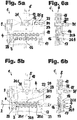
- the 5a and 6a show the straightening device 1 in an open position.
- the rollers of the two rows of rollers 3, 4 are spaced so far apart that a sufficiently large space is created through which the cable can be inserted.
- the rows of rollers are preferably first shifted against one another in the vertical direction by means of a quick-release device comprising the quick-release lever 31.
- the parallel rollers of the upper and lower roller rows 3, 4 are close to the cable, so that the actual setting of the straightening device 1 can now be started.
- the user can now turn the knob 19 of the adjusting device 5 clockwise, whereby the upper roller plate 18 is moved with the upper roller row 4 down against the lower roller row 3.
- the user executes this relative infeed movement by manually actuating the setting device 5 until the rollers 20.1 .. 20.6 of the first row of rollers 3 and the rollers 21.1 .. 21.7 of the second row of rollers 4 contact the cable 2.
- the user can determine the approximate contact by eye. Then he checks the display device 8. If the error display element 22 lights up red, then the rows of rollers 3 and 4 are still too far apart. In other words, the measured actual value for the distance d between the rollers 20.1 .. 20.6 and the rollers 21.1 .. 21.7 of the first or the second row of rollers 3, 4 compared to the target value for the roller distance d is too high.
- the user On the basis of the display device 8, the user is thus indirectly instructed to continue to turn the rotary knob 19 in the same direction of rotation. He does this until the good display element 24, which illuminates the display device 8 green. A good signal is generated which indicates that the actual value of the roller distance corresponds to the corresponding target value. If the user turns the rotary knob 19 for too long, the error display element 23 lights up red due to the insufficient roller spacing.
- the measured value for the roller distance d is shown on a digital display 25, the three LEDs of the error display elements 22, 23 and the good display element 24 signal to the user whether he should close or open the straightening device 1 in order to achieve the desired setpoint for the roller distance.
- the operator turns the rotary knob 19 until the green LED of the good indicator element 24 lights up when the desired value is reached.
- the control unit 7 assigned to the machine control then releases the production of the cable.
- the active position in which the straightening device 1 is correctly set is in 5b and 6b shown. If necessary, after setting the roller spacing, the angular position of the roller rows 3, 4 can be changed in a conventional manner by switching on or automatically actuating the pneumatic cylinder 9. The angular position of the rows of rollers 3, 4 could, however, also be changed manually after a corresponding redesign of the straightening device 1 and set in an analogous manner to the roller spacing.
Landscapes
- Engineering & Computer Science (AREA)
- Mechanical Engineering (AREA)
- Manufacturing & Machinery (AREA)
- Wire Processing (AREA)
- Storing, Repeated Paying-Out, And Re-Storing Of Elongated Articles (AREA)
- Ropes Or Cables (AREA)
Claims (12)
- Dispositif d'alignement (1), destiné à aligner des câbles (2) comprenant :- une première rangée de galets (3) et une deuxième rangée de galets (4), le câble (2) étant susceptible d'être passé dans une direction de transport (x), alternativement chaque fois entre des galets (20.1 ... 20.6) de la première rangée de galets (3) et des galets (21.1 ... 21.7) de la deuxième rangée de galets (4),- un système de réglage (5), destiné au réglage manuel d'un écart (d) entre les galets (20.1 ... 20.6 ; 21.1 ... 21.7) de la première et de la deuxième rangées de galets (3, 4),- un système de mesure (6), destiné à détecter au moins l'écart (d) entre les galets (20.1 ... 20.6 ; 21.1 ... ; 21.7) de la première et de la deuxième rangées de galets (3, 4),caractérisé en ce que le dispositif d'alignement (1) comporte un système de signalisation (8), permettant de signaler par voie visuelle, acoustique et/ou tactile des différences entre une valeur réelle déterminée au moyen du système de mesure (6) et une valeur de consigne de l'écart (d).
- Dispositif d'alignement (1) selon la revendication 1, caractérisé en ce que le système de signalisation (8) comprend au moins un élément de signalisation des défauts (22, 23), destiné à signaler une valeur réelle trop élevée par rapport à la valeur de consigne des écart (d) et/ou à signaler une valeur réelle trop faible par rapport à la valeur de consigne de l'écart (d).
- Dispositif d'alignement (1) selon la revendication 1 ou 2, caractérisé en ce que le système de signalisation (8) comprend au moins un élément de signalisation optique des défauts (22, 23), destiné à signaler une valeur réelle trop élevée et/ou une valeur réelle trop faible par rapport à la valeur de consigne de l'écart (d), l'au moins un élément de signalisation optique des défauts (22, 23) comportant des moyens lumineux, de préférence sur base de DEL.
- Dispositif d'alignement (1) selon la revendication 3, caractérisé en ce que le système de signalisation (8) comprend un système optique de signalisation de conformité (24), destiné à signaler que la valeur réelle coïncide avec la valeur de consigne.
- Dispositif d'alignement (1) selon l'une quelconque des revendications 1 à 4, caractérisé en ce que le système de signalisation (8) comprend deux éléments de signalisation des défauts (22, 23) et un élément de signalisation de conformité (24), l'élément de signalisation de conformité (24) étant placé de préférence entre les éléments de signalisation des défauts (22, 23).
- Dispositif d'alignement (1) selon la revendication 5, caractérisé en ce que les éléments de signalisation des défauts (22, 23) et l'élément de signalisation de conformité (24) sont conçus de sorte à pouvoir s'allumer dans différentes couleurs.
- Dispositif d'alignement (1) selon l'une quelconque des revendications 1 à 6, caractérisé en ce que le système de signalisation (8) comprend un affichage numérique (25), destiné à afficher numériquement l'écart (d).
- Dispositif d'alignement (1) selon l'une quelconque des revendications 1 à 7, caractérisé en ce que le système de mesure (6) destiné à détecter l'écart (d) entre les galets (20.1 ... 20.6 ; 21.1 ... 21.7) du premier et du deuxième agencements de galets (3, 4) comporte un capteur de course potentiométrique.
- Dispositif d'alignement (1) selon l'une quelconque des revendications 1 à 8, caractérisé en ce que le système de mesure (8) est connecté ou susceptible d'être connecté sur une unité de mémoire (26), à l'aide de laquelle, aux fins d'une documentation, les valeurs réelles et/ou les différences entre les valeurs réelles et la valeur de consigne des écart (d) sont enregistrées.
- Dispositif d'alignement (1) selon l'une quelconque des revendications 1 à 9, caractérisé en ce que le système de mesure (6) est connecté ou susceptible d'être connecté sur un système de commande (7) et en ce que le système de commande (7) est programmé de telle sorte qu'un fonctionnement en production, lors duquel pour l'alignement du câble, le câble (2) est tiré entre les galets (20.1 ... 20.6 ; 21.1 ... 21.7) de la première et de la deuxième rangées de galets (3, 4) soit bloqué aussi longtemps que la valeur réelle ne coïncide pas avec la valeur de consigne.
- Dispositif d'alignement (1) selon l'une quelconque des revendications 1 à 10, caractérisé en ce que pour le réglage manuel de l'écart (d) entre les galets (20.1 ... 20.6 ; 21.1 ... 21.7) de la première et de la deuxième rangées de galets (3, 4), le système de réglage (5) comporte un bouton rotatif ou une vis de réglage (19).
- Procédé opératoire d'un dispositif d'alignement (1) selon l'une quelconque des revendications 1 à 11, dans une première étape a) étant réalisé ce qui suit :a) l'introduction d'un câble (1) qu'il s'agit d'aligner dans un espace intermédiaire entre des galets (20.1 ... 20.6) d'une première rangée de galets (3) et des galets (21.1 ... 21.7) d'une deuxième rangée de galets (4) opposée à la première rangée de galets (3), caractérisé en ce qu'après l'étape a), les étapes suivantes sont réalisées :b) la réalisation d'un mouvement d'approche relative, par actionnement manuel d'un système de réglage (5), pour amener les galets (20.1... 20.6) de la première rangée de galets (3) et les galets (21.1 ... 21.7) de la deuxième rangée de galets (4) en contact avec le câble (2) ;c) la détermination d'une valeur réelle au moins de l'écart (d), au moyen d'un système de mesure (6),d) la comparaison de la valeur réelle déterminée au moyen du système de mesure (6) avec une valeur de consigne pour l'écart (d), dans un système de commande (7),e) si une différence inadmissible résulte de la comparaison dans l'étape d), un système de signalisation (8) délivre un signal de défaut visuel, acoustique et/ou tactile, pour guider l'opérateur,f) le mouvement d'approche relative est poursuivi par un actionnement manuel d'un système de réglage (5) selon l'étape b) et les étapes c) à e) sont réitérées, jusqu'au ce que le signal de défaut du système de signalisation (8) disparaisse et/ou jusqu'à ce que le système de signalisation (8) génère un signal de conformité pour signaler que la valeur réelle coïncide avec la valeur de consigne.
Priority Applications (7)
| Application Number | Priority Date | Filing Date | Title |
|---|---|---|---|
| EP15201628.3A EP3184191B1 (fr) | 2015-12-21 | 2015-12-21 | Dispositif d'alignement des conducteurs |
| RS20200443A RS60196B1 (sr) | 2015-12-21 | 2015-12-21 | Uređaj za ispravljanje kablova |
| JP2016227530A JP2017113805A (ja) | 2015-12-21 | 2016-11-24 | ケーブルをまっすぐにするための矯正装置 |
| US15/364,348 US10773285B2 (en) | 2015-12-21 | 2016-11-30 | Straightening device for straightening cables |
| CN201611164399.2A CN107039872B (zh) | 2015-12-21 | 2016-12-15 | 用于校直电缆的校直装置 |
| JP2021094912A JP2021130138A (ja) | 2015-12-21 | 2021-06-07 | ケーブルをまっすぐにするための矯正装置 |
| JP2023114939A JP2023134637A (ja) | 2015-12-21 | 2023-07-13 | ケーブルをまっすぐにするための矯正装置 |
Applications Claiming Priority (1)
| Application Number | Priority Date | Filing Date | Title |
|---|---|---|---|
| EP15201628.3A EP3184191B1 (fr) | 2015-12-21 | 2015-12-21 | Dispositif d'alignement des conducteurs |
Publications (2)
| Publication Number | Publication Date |
|---|---|
| EP3184191A1 EP3184191A1 (fr) | 2017-06-28 |
| EP3184191B1 true EP3184191B1 (fr) | 2020-02-05 |
Family
ID=55024881
Family Applications (1)
| Application Number | Title | Priority Date | Filing Date |
|---|---|---|---|
| EP15201628.3A Active EP3184191B1 (fr) | 2015-12-21 | 2015-12-21 | Dispositif d'alignement des conducteurs |
Country Status (5)
| Country | Link |
|---|---|
| US (1) | US10773285B2 (fr) |
| EP (1) | EP3184191B1 (fr) |
| JP (3) | JP2017113805A (fr) |
| CN (1) | CN107039872B (fr) |
| RS (1) | RS60196B1 (fr) |
Families Citing this family (17)
| Publication number | Priority date | Publication date | Assignee | Title |
|---|---|---|---|---|
| WO2019111039A1 (fr) * | 2017-12-05 | 2019-06-13 | Tecnomatic Spa | Appareil et procédé pour traiter un produit semi-traité continu |
| US20190240721A1 (en) * | 2018-02-05 | 2019-08-08 | Kenneth A. Fullick | Machine and Method of Introducing a Camber into a Length of Wire |
| EP3873687A1 (fr) * | 2018-10-31 | 2021-09-08 | Schleuniger AG | Dispositif de redressage destiné à une machine de traitement de câble et procédé de fonctionnement d'une machine de redressage |
| CN109482780A (zh) * | 2018-11-09 | 2019-03-19 | 东华大学 | 制造导纱针用扁丝矫直机构 |
| DE202019106612U1 (de) * | 2019-04-12 | 2020-01-21 | UGM-Holding AS | Vorrichtung zum Reduzieren eingebetteter oder eigener Reibung in einem Mehrleitungsrohr |
| CN109896342A (zh) * | 2019-04-28 | 2019-06-18 | 杨迪章 | 一种节能环保型漆包线防跑偏自动化收卷装置 |
| WO2021024363A1 (fr) * | 2019-08-05 | 2021-02-11 | 新明和工業株式会社 | Dispositif de redressement de fil électrique, dispositif de traitement de fil électrique équipé de celui-ci, procédé de redressement de fil électrique et son procédé de fabrication |
| DE102019212090B4 (de) * | 2019-08-13 | 2024-02-01 | Wafios Aktiengesellschaft | Umformmaschine mit Einzugseinrichtung |
| JP6785399B1 (ja) * | 2019-10-11 | 2020-11-18 | 新明和工業株式会社 | 電線矯正装置、それを備えた電線処理装置、および電線矯正方法 |
| EP3812060B1 (fr) * | 2019-10-21 | 2022-11-30 | Komax Holding Ag | Appareil pour le dressage de câbles |
| CN110695140B (zh) * | 2019-10-24 | 2024-04-02 | 亚太轻合金(南通)科技有限公司 | 智能自动调节圆管、圆棒矫直机及其加工方法 |
| CN110788246B (zh) * | 2019-11-04 | 2021-09-17 | 国网河南省电力公司偃师市供电公司 | 一种电缆检测及拉直装置 |
| CN110947869A (zh) * | 2019-12-25 | 2020-04-03 | 国网辽宁省电力有限公司沈阳供电公司 | 一种高压线专用防松散装置 |
| US11701694B2 (en) * | 2021-06-11 | 2023-07-18 | Primetals Technologies USA LLC | Automated calibration and realtime communication of data, problems, damage, manipulation, and failure from a network of battery powered smart guide nodes within a rolling mill |
| CN114030944A (zh) * | 2021-10-19 | 2022-02-11 | 国网河南省电力公司洛宁县供电公司 | 一种高压线引线装置 |
| CN116765283B (zh) * | 2023-06-01 | 2023-12-19 | 苏州索力伊智能科技有限公司 | 基于裁剥铆拧一体机的校正系统及其方法 |
| CN116727564B (zh) * | 2023-06-26 | 2024-01-19 | 阳谷华东特种电缆有限公司 | 一种电缆加工用矫正设备及方法 |
Citations (2)
| Publication number | Priority date | Publication date | Assignee | Title |
|---|---|---|---|---|
| DE10259257A1 (de) * | 2002-12-11 | 2004-06-24 | Marquart, Ingeborg | Vorrichtung und Verfahren zum zentrierten Spannen von rotierend antreibbaren Teilen |
| DE102009007977A1 (de) * | 2009-02-06 | 2009-07-23 | Konrad, Hilmar, Dipl.-Ing. | Handwerkzeugmaschine mit Drehratensensor |
Family Cites Families (18)
| Publication number | Priority date | Publication date | Assignee | Title |
|---|---|---|---|---|
| US1113121A (en) * | 1913-09-20 | 1914-10-06 | California Fuel Mfg Company | Material-compressing machine. |
| US2123124A (en) * | 1937-11-26 | 1938-07-05 | Smith Lewie Roberts | Grass guard for mowers |
| DE1034576B (de) * | 1954-11-16 | 1958-07-24 | Evg Entwicklung Verwert Ges | Vorrichtung zum Richten von Draehten |
| IT1143544B (it) * | 1981-04-13 | 1986-10-22 | Hs Hydraulic Systems Srl | Laminatoio per anelli |
| JPS6289529A (ja) * | 1985-10-14 | 1987-04-24 | Kawasaki Steel Corp | 形鋼のロ−ラ矯正方法及び装置 |
| DE3840016A1 (de) * | 1988-11-26 | 1990-05-31 | Schloemann Siemag Ag | Verfahren zum richten von blechen, baendern, tafeln, profilen, traegern etc. |
| US5676010A (en) * | 1996-09-20 | 1997-10-14 | The Whitaker Corporation | Wire straightening device |
| FR2860738B1 (fr) * | 2003-10-13 | 2006-02-03 | Vai Clecim | Procede d'augmentation de la precision du controle de la trajectoire du produit dans une machine a planer a rouleaux imbriques et installation de planage permettant la mise en oeuvre du procede. |
| US7383711B2 (en) * | 2005-06-10 | 2008-06-10 | Blue Ip, Inc. | CNC leveler |
| DE102007009946A1 (de) * | 2006-03-30 | 2007-10-18 | Sms Meer Gmbh | Verfahren zur Qualitätssicherung beim Walzen eines Rundprofils |
| JP2009172642A (ja) | 2008-01-24 | 2009-08-06 | Furukawa Electric Co Ltd:The | 線状体矯正装置及び線状体製造装置 |
| CN102099132B (zh) * | 2008-07-10 | 2014-07-30 | 阿库机械制造有限公司 | 用于在辊式矫平机中矫平部件的方法 |
| CN201596726U (zh) | 2009-12-16 | 2010-10-06 | 福建省金得利集团有限公司 | 一种剪铜线装置 |
| CN102366803B (zh) * | 2010-06-23 | 2015-09-02 | 科马斯控股股份公司 | 用于矫直线缆的矫直装置以及相应的方法 |
| RU2602216C2 (ru) * | 2011-09-14 | 2016-11-10 | Смс Меер Гмбх | Прокатный стан, а также устройство и способ определения прокатного или направляющего калибра прокатных или направляющих клетей в многоклетевом прокатном стане |
| CN102601273A (zh) * | 2012-03-28 | 2012-07-25 | 无锡兆一锻压数控装备有限公司 | 带数字显示的校直机 |
| CN202506786U (zh) | 2012-03-30 | 2012-10-31 | 巩飞 | 一种制圈机 |
| CN104942183B (zh) | 2015-06-15 | 2017-05-24 | 中山市亚泰机械实业有限公司 | 送线机构的前置检测校直装置 |
-
2015
- 2015-12-21 EP EP15201628.3A patent/EP3184191B1/fr active Active
- 2015-12-21 RS RS20200443A patent/RS60196B1/sr unknown
-
2016
- 2016-11-24 JP JP2016227530A patent/JP2017113805A/ja active Pending
- 2016-11-30 US US15/364,348 patent/US10773285B2/en active Active
- 2016-12-15 CN CN201611164399.2A patent/CN107039872B/zh active Active
-
2021
- 2021-06-07 JP JP2021094912A patent/JP2021130138A/ja active Pending
-
2023
- 2023-07-13 JP JP2023114939A patent/JP2023134637A/ja active Pending
Patent Citations (2)
| Publication number | Priority date | Publication date | Assignee | Title |
|---|---|---|---|---|
| DE10259257A1 (de) * | 2002-12-11 | 2004-06-24 | Marquart, Ingeborg | Vorrichtung und Verfahren zum zentrierten Spannen von rotierend antreibbaren Teilen |
| DE102009007977A1 (de) * | 2009-02-06 | 2009-07-23 | Konrad, Hilmar, Dipl.-Ing. | Handwerkzeugmaschine mit Drehratensensor |
Also Published As
| Publication number | Publication date |
|---|---|
| RS60196B1 (sr) | 2020-06-30 |
| CN107039872B (zh) | 2020-10-23 |
| JP2017113805A (ja) | 2017-06-29 |
| CN107039872A (zh) | 2017-08-11 |
| US20170173652A1 (en) | 2017-06-22 |
| JP2023134637A (ja) | 2023-09-27 |
| EP3184191A1 (fr) | 2017-06-28 |
| US10773285B2 (en) | 2020-09-15 |
| JP2021130138A (ja) | 2021-09-09 |
Similar Documents
| Publication | Publication Date | Title |
|---|---|---|
| EP3184191B1 (fr) | Dispositif d'alignement des conducteurs | |
| EP0796158B1 (fr) | Procede et dispositif de production optimisee de ressorts helicoidaux sur des machines automatiques a enrouler les ressorts | |
| EP2399856A1 (fr) | Dispositif d'orientation destiné à orienter des câbles et procédé correspondant | |
| DE2015967A1 (de) | Verfahren und Vorrichtung zur Herstellung von verschraubten Rohrverbindungen | |
| EP3301768A1 (fr) | Procédé et dispositif pour l'alignement d'extrémités de câble préparés d'un faisceau de câbles | |
| DE102015208350B3 (de) | Verfahren zur Herstellung von Formteilen und Umformmaschine zur Durchführung des Verfahrens | |
| EP3426421A1 (fr) | Dispositif de fabrication de cages d'armature | |
| EP2313235A1 (fr) | Procédé de surveillance de l'état d'usure d'une pince manuelle et dispositif à cet effet | |
| EP3614821A1 (fr) | Robots de câblage et procédé de câblage, système et procédé de planification de câblages, système et procédé de détection de composants | |
| WO2019207344A1 (fr) | Dispositif de torsadage et procédé pour la détermination ou la vérification d'une longueur de pas d'un faisceau de lignes, procédé mis en œuvre par ordinateur ainsi que produit de programme informatique et un kit de mise à niveau correspondant | |
| EP3873687A1 (fr) | Dispositif de redressage destiné à une machine de traitement de câble et procédé de fonctionnement d'une machine de redressage | |
| EP3965973A1 (fr) | Machine de formage et procédé de production de pièces cintrées à partir d'un matériau allongé isolé doté d'extrémités dénudées | |
| DE69103304T2 (de) | Steuereinrichtung für einen automatisierten Kabel-Wickler. | |
| EP2152445B1 (fr) | Procédé et dispositif pour ajuster un poste d'assouplissement pendant le cintrage de tôles | |
| DE3804913A1 (de) | Vorrichtung und verfahren zur herstellung von federn | |
| DE19932962B4 (de) | Zange mit Wegmeßeinrichtung und zugehörigen Verfahren zur Kraft-Weg-Messung | |
| EP3012842B1 (fr) | Dispositif de toronnage avec écart réglable des extrémités de ligne | |
| DE2901376B2 (de) | Steuereinrichtung an Freibiegemaschinen | |
| EP3158288B1 (fr) | Dispositif de mesure d'angles de pliage destiné à une presse de pliage | |
| EP1383212B1 (fr) | Appareil et procédé pour l'assurance de la qualité de connexions de sertissage | |
| DE4111404C2 (fr) | ||
| CH713739A2 (de) | Verfahren und Vorrichtung zur Rollnahtschweissung von Behälterzargen. | |
| EP1757522B1 (fr) | Procédé et dispositif pour sceller avec des clips des paquets avec la forme d'une saucisse | |
| DE102014206251B3 (de) | Wickelvorrichtung und Verfahren zu deren Betrieb | |
| DE102006051300A1 (de) | Vorrichtung zum Strecken bzw. Glätten und/oder Ausrichten von Teigrohlingen, insbesondere von zur Brezelherstellung vorgeformten Teigsträngen und Verfahren zum Betreiben der Vorrichtung |
Legal Events
| Date | Code | Title | Description |
|---|---|---|---|
| PUAI | Public reference made under article 153(3) epc to a published international application that has entered the european phase |
Free format text: ORIGINAL CODE: 0009012 |
|
| STAA | Information on the status of an ep patent application or granted ep patent |
Free format text: STATUS: THE APPLICATION HAS BEEN PUBLISHED |
|
| AK | Designated contracting states |
Kind code of ref document: A1 Designated state(s): AL AT BE BG CH CY CZ DE DK EE ES FI FR GB GR HR HU IE IS IT LI LT LU LV MC MK MT NL NO PL PT RO RS SE SI SK SM TR |
|
| AX | Request for extension of the european patent |
Extension state: BA ME |
|
| STAA | Information on the status of an ep patent application or granted ep patent |
Free format text: STATUS: REQUEST FOR EXAMINATION WAS MADE |
|
| 17P | Request for examination filed |
Effective date: 20171219 |
|
| RBV | Designated contracting states (corrected) |
Designated state(s): AL AT BE BG CH CY CZ DE DK EE ES FI FR GB GR HR HU IE IS IT LI LT LU LV MC MK MT NL NO PL PT RO RS SE SI SK SM TR |
|
| STAA | Information on the status of an ep patent application or granted ep patent |
Free format text: STATUS: EXAMINATION IS IN PROGRESS |
|
| 17Q | First examination report despatched |
Effective date: 20180425 |
|
| GRAP | Despatch of communication of intention to grant a patent |
Free format text: ORIGINAL CODE: EPIDOSNIGR1 |
|
| STAA | Information on the status of an ep patent application or granted ep patent |
Free format text: STATUS: GRANT OF PATENT IS INTENDED |
|
| INTG | Intention to grant announced |
Effective date: 20190723 |
|
| GRAS | Grant fee paid |
Free format text: ORIGINAL CODE: EPIDOSNIGR3 |
|
| GRAA | (expected) grant |
Free format text: ORIGINAL CODE: 0009210 |
|
| STAA | Information on the status of an ep patent application or granted ep patent |
Free format text: STATUS: THE PATENT HAS BEEN GRANTED |
|
| AK | Designated contracting states |
Kind code of ref document: B1 Designated state(s): AL AT BE BG CH CY CZ DE DK EE ES FI FR GB GR HR HU IE IS IT LI LT LU LV MC MK MT NL NO PL PT RO RS SE SI SK SM TR |
|
| REG | Reference to a national code |
Ref country code: GB Ref legal event code: FG4D Free format text: NOT ENGLISH |
|
| REG | Reference to a national code |
Ref country code: CH Ref legal event code: NV Representative=s name: INVENTIO AG, CH |
|
| REG | Reference to a national code |
Ref country code: AT Ref legal event code: REF Ref document number: 1229545 Country of ref document: AT Kind code of ref document: T Effective date: 20200215 |
|
| REG | Reference to a national code |
Ref country code: DE Ref legal event code: R096 Ref document number: 502015011632 Country of ref document: DE |
|
| REG | Reference to a national code |
Ref country code: IE Ref legal event code: FG4D Free format text: LANGUAGE OF EP DOCUMENT: GERMAN |
|
| REG | Reference to a national code |
Ref country code: CH Ref legal event code: EP |
|
| REG | Reference to a national code |
Ref country code: RO Ref legal event code: EPE |
|
| REG | Reference to a national code |
Ref country code: NL Ref legal event code: MP Effective date: 20200205 |
|
| PG25 | Lapsed in a contracting state [announced via postgrant information from national office to epo] |
Ref country code: PT Free format text: LAPSE BECAUSE OF FAILURE TO SUBMIT A TRANSLATION OF THE DESCRIPTION OR TO PAY THE FEE WITHIN THE PRESCRIBED TIME-LIMIT Effective date: 20200628 Ref country code: FI Free format text: LAPSE BECAUSE OF FAILURE TO SUBMIT A TRANSLATION OF THE DESCRIPTION OR TO PAY THE FEE WITHIN THE PRESCRIBED TIME-LIMIT Effective date: 20200205 Ref country code: NO Free format text: LAPSE BECAUSE OF FAILURE TO SUBMIT A TRANSLATION OF THE DESCRIPTION OR TO PAY THE FEE WITHIN THE PRESCRIBED TIME-LIMIT Effective date: 20200505 |
|
| REG | Reference to a national code |
Ref country code: LT Ref legal event code: MG4D |
|
| PG25 | Lapsed in a contracting state [announced via postgrant information from national office to epo] |
Ref country code: BG Free format text: LAPSE BECAUSE OF FAILURE TO SUBMIT A TRANSLATION OF THE DESCRIPTION OR TO PAY THE FEE WITHIN THE PRESCRIBED TIME-LIMIT Effective date: 20200505 Ref country code: GR Free format text: LAPSE BECAUSE OF FAILURE TO SUBMIT A TRANSLATION OF THE DESCRIPTION OR TO PAY THE FEE WITHIN THE PRESCRIBED TIME-LIMIT Effective date: 20200506 Ref country code: HR Free format text: LAPSE BECAUSE OF FAILURE TO SUBMIT A TRANSLATION OF THE DESCRIPTION OR TO PAY THE FEE WITHIN THE PRESCRIBED TIME-LIMIT Effective date: 20200205 Ref country code: IS Free format text: LAPSE BECAUSE OF FAILURE TO SUBMIT A TRANSLATION OF THE DESCRIPTION OR TO PAY THE FEE WITHIN THE PRESCRIBED TIME-LIMIT Effective date: 20200605 Ref country code: SE Free format text: LAPSE BECAUSE OF FAILURE TO SUBMIT A TRANSLATION OF THE DESCRIPTION OR TO PAY THE FEE WITHIN THE PRESCRIBED TIME-LIMIT Effective date: 20200205 Ref country code: LV Free format text: LAPSE BECAUSE OF FAILURE TO SUBMIT A TRANSLATION OF THE DESCRIPTION OR TO PAY THE FEE WITHIN THE PRESCRIBED TIME-LIMIT Effective date: 20200205 |
|
| PG25 | Lapsed in a contracting state [announced via postgrant information from national office to epo] |
Ref country code: NL Free format text: LAPSE BECAUSE OF FAILURE TO SUBMIT A TRANSLATION OF THE DESCRIPTION OR TO PAY THE FEE WITHIN THE PRESCRIBED TIME-LIMIT Effective date: 20200205 |
|
| PG25 | Lapsed in a contracting state [announced via postgrant information from national office to epo] |
Ref country code: DK Free format text: LAPSE BECAUSE OF FAILURE TO SUBMIT A TRANSLATION OF THE DESCRIPTION OR TO PAY THE FEE WITHIN THE PRESCRIBED TIME-LIMIT Effective date: 20200205 Ref country code: SK Free format text: LAPSE BECAUSE OF FAILURE TO SUBMIT A TRANSLATION OF THE DESCRIPTION OR TO PAY THE FEE WITHIN THE PRESCRIBED TIME-LIMIT Effective date: 20200205 Ref country code: SM Free format text: LAPSE BECAUSE OF FAILURE TO SUBMIT A TRANSLATION OF THE DESCRIPTION OR TO PAY THE FEE WITHIN THE PRESCRIBED TIME-LIMIT Effective date: 20200205 Ref country code: EE Free format text: LAPSE BECAUSE OF FAILURE TO SUBMIT A TRANSLATION OF THE DESCRIPTION OR TO PAY THE FEE WITHIN THE PRESCRIBED TIME-LIMIT Effective date: 20200205 Ref country code: LT Free format text: LAPSE BECAUSE OF FAILURE TO SUBMIT A TRANSLATION OF THE DESCRIPTION OR TO PAY THE FEE WITHIN THE PRESCRIBED TIME-LIMIT Effective date: 20200205 Ref country code: ES Free format text: LAPSE BECAUSE OF FAILURE TO SUBMIT A TRANSLATION OF THE DESCRIPTION OR TO PAY THE FEE WITHIN THE PRESCRIBED TIME-LIMIT Effective date: 20200205 Ref country code: CZ Free format text: LAPSE BECAUSE OF FAILURE TO SUBMIT A TRANSLATION OF THE DESCRIPTION OR TO PAY THE FEE WITHIN THE PRESCRIBED TIME-LIMIT Effective date: 20200205 |
|
| REG | Reference to a national code |
Ref country code: DE Ref legal event code: R097 Ref document number: 502015011632 Country of ref document: DE |
|
| PLBE | No opposition filed within time limit |
Free format text: ORIGINAL CODE: 0009261 |
|
| STAA | Information on the status of an ep patent application or granted ep patent |
Free format text: STATUS: NO OPPOSITION FILED WITHIN TIME LIMIT |
|
| 26N | No opposition filed |
Effective date: 20201106 |
|
| PG25 | Lapsed in a contracting state [announced via postgrant information from national office to epo] |
Ref country code: PL Free format text: LAPSE BECAUSE OF FAILURE TO SUBMIT A TRANSLATION OF THE DESCRIPTION OR TO PAY THE FEE WITHIN THE PRESCRIBED TIME-LIMIT Effective date: 20200205 Ref country code: SI Free format text: LAPSE BECAUSE OF FAILURE TO SUBMIT A TRANSLATION OF THE DESCRIPTION OR TO PAY THE FEE WITHIN THE PRESCRIBED TIME-LIMIT Effective date: 20200205 |
|
| GBPC | Gb: european patent ceased through non-payment of renewal fee |
Effective date: 20201221 |
|
| PG25 | Lapsed in a contracting state [announced via postgrant information from national office to epo] |
Ref country code: MC Free format text: LAPSE BECAUSE OF FAILURE TO SUBMIT A TRANSLATION OF THE DESCRIPTION OR TO PAY THE FEE WITHIN THE PRESCRIBED TIME-LIMIT Effective date: 20200205 |
|
| REG | Reference to a national code |
Ref country code: BE Ref legal event code: MM Effective date: 20201231 |
|
| PG25 | Lapsed in a contracting state [announced via postgrant information from national office to epo] |
Ref country code: FR Free format text: LAPSE BECAUSE OF NON-PAYMENT OF DUE FEES Effective date: 20201231 Ref country code: LU Free format text: LAPSE BECAUSE OF NON-PAYMENT OF DUE FEES Effective date: 20201221 Ref country code: IE Free format text: LAPSE BECAUSE OF NON-PAYMENT OF DUE FEES Effective date: 20201221 |
|
| PG25 | Lapsed in a contracting state [announced via postgrant information from national office to epo] |
Ref country code: GB Free format text: LAPSE BECAUSE OF NON-PAYMENT OF DUE FEES Effective date: 20201221 |
|
| REG | Reference to a national code |
Ref country code: AT Ref legal event code: MM01 Ref document number: 1229545 Country of ref document: AT Kind code of ref document: T Effective date: 20201221 |
|
| PG25 | Lapsed in a contracting state [announced via postgrant information from national office to epo] |
Ref country code: AT Free format text: LAPSE BECAUSE OF NON-PAYMENT OF DUE FEES Effective date: 20201221 |
|
| PG25 | Lapsed in a contracting state [announced via postgrant information from national office to epo] |
Ref country code: TR Free format text: LAPSE BECAUSE OF FAILURE TO SUBMIT A TRANSLATION OF THE DESCRIPTION OR TO PAY THE FEE WITHIN THE PRESCRIBED TIME-LIMIT Effective date: 20200205 Ref country code: MT Free format text: LAPSE BECAUSE OF FAILURE TO SUBMIT A TRANSLATION OF THE DESCRIPTION OR TO PAY THE FEE WITHIN THE PRESCRIBED TIME-LIMIT Effective date: 20200205 Ref country code: CY Free format text: LAPSE BECAUSE OF FAILURE TO SUBMIT A TRANSLATION OF THE DESCRIPTION OR TO PAY THE FEE WITHIN THE PRESCRIBED TIME-LIMIT Effective date: 20200205 |
|
| PG25 | Lapsed in a contracting state [announced via postgrant information from national office to epo] |
Ref country code: MK Free format text: LAPSE BECAUSE OF FAILURE TO SUBMIT A TRANSLATION OF THE DESCRIPTION OR TO PAY THE FEE WITHIN THE PRESCRIBED TIME-LIMIT Effective date: 20200205 Ref country code: AL Free format text: LAPSE BECAUSE OF FAILURE TO SUBMIT A TRANSLATION OF THE DESCRIPTION OR TO PAY THE FEE WITHIN THE PRESCRIBED TIME-LIMIT Effective date: 20200205 |
|
| PG25 | Lapsed in a contracting state [announced via postgrant information from national office to epo] |
Ref country code: BE Free format text: LAPSE BECAUSE OF NON-PAYMENT OF DUE FEES Effective date: 20201231 |
|
| PGFP | Annual fee paid to national office [announced via postgrant information from national office to epo] |
Ref country code: RS Payment date: 20231208 Year of fee payment: 9 Ref country code: RO Payment date: 20231213 Year of fee payment: 9 Ref country code: IT Payment date: 20231221 Year of fee payment: 9 |
|
| PGFP | Annual fee paid to national office [announced via postgrant information from national office to epo] |
Ref country code: DE Payment date: 20231227 Year of fee payment: 9 Ref country code: CH Payment date: 20240102 Year of fee payment: 9 |