EP3181790A1 - Schiebesystem für fenster oder türen - Google Patents
Schiebesystem für fenster oder türen Download PDFInfo
- Publication number
- EP3181790A1 EP3181790A1 EP16203778.2A EP16203778A EP3181790A1 EP 3181790 A1 EP3181790 A1 EP 3181790A1 EP 16203778 A EP16203778 A EP 16203778A EP 3181790 A1 EP3181790 A1 EP 3181790A1
- Authority
- EP
- European Patent Office
- Prior art keywords
- wing
- sliding system
- sealing element
- magnetic
- seal
- Prior art date
- Legal status (The legal status is an assumption and is not a legal conclusion. Google has not performed a legal analysis and makes no representation as to the accuracy of the status listed.)
- Withdrawn
Links
- 238000007789 sealing Methods 0.000 claims abstract description 68
- 239000011521 glass Substances 0.000 claims abstract description 5
- 238000006073 displacement reaction Methods 0.000 claims description 12
- BHMLFPOTZYRDKA-IRXDYDNUSA-N (2s)-2-[(s)-(2-iodophenoxy)-phenylmethyl]morpholine Chemical compound IC1=CC=CC=C1O[C@@H](C=1C=CC=CC=1)[C@H]1OCCNC1 BHMLFPOTZYRDKA-IRXDYDNUSA-N 0.000 claims 1
- 230000000694 effects Effects 0.000 description 3
- 230000002349 favourable effect Effects 0.000 description 1
- 239000012530 fluid Substances 0.000 description 1
- 238000009434 installation Methods 0.000 description 1
- 239000000463 material Substances 0.000 description 1
- 230000001846 repelling effect Effects 0.000 description 1
Images


Classifications
-
- E—FIXED CONSTRUCTIONS
- E06—DOORS, WINDOWS, SHUTTERS, OR ROLLER BLINDS IN GENERAL; LADDERS
- E06B—FIXED OR MOVABLE CLOSURES FOR OPENINGS IN BUILDINGS, VEHICLES, FENCES OR LIKE ENCLOSURES IN GENERAL, e.g. DOORS, WINDOWS, BLINDS, GATES
- E06B3/00—Window sashes, door leaves, or like elements for closing wall or like openings; Layout of fixed or moving closures, e.g. windows in wall or like openings; Features of rigidly-mounted outer frames relating to the mounting of wing frames
- E06B3/32—Arrangements of wings characterised by the manner of movement; Arrangements of movable wings in openings; Features of wings or frames relating solely to the manner of movement of the wing
- E06B3/34—Arrangements of wings characterised by the manner of movement; Arrangements of movable wings in openings; Features of wings or frames relating solely to the manner of movement of the wing with only one kind of movement
- E06B3/42—Sliding wings; Details of frames with respect to guiding
- E06B3/46—Horizontally-sliding wings
-
- E—FIXED CONSTRUCTIONS
- E06—DOORS, WINDOWS, SHUTTERS, OR ROLLER BLINDS IN GENERAL; LADDERS
- E06B—FIXED OR MOVABLE CLOSURES FOR OPENINGS IN BUILDINGS, VEHICLES, FENCES OR LIKE ENCLOSURES IN GENERAL, e.g. DOORS, WINDOWS, BLINDS, GATES
- E06B3/00—Window sashes, door leaves, or like elements for closing wall or like openings; Layout of fixed or moving closures, e.g. windows in wall or like openings; Features of rigidly-mounted outer frames relating to the mounting of wing frames
- E06B3/32—Arrangements of wings characterised by the manner of movement; Arrangements of movable wings in openings; Features of wings or frames relating solely to the manner of movement of the wing
- E06B3/50—Arrangements of wings characterised by the manner of movement; Arrangements of movable wings in openings; Features of wings or frames relating solely to the manner of movement of the wing with more than one kind of movement
- E06B3/52—Wings requiring lifting before opening
-
- E—FIXED CONSTRUCTIONS
- E05—LOCKS; KEYS; WINDOW OR DOOR FITTINGS; SAFES
- E05C—BOLTS OR FASTENING DEVICES FOR WINGS, SPECIALLY FOR DOORS OR WINDOWS
- E05C19/00—Other devices specially designed for securing wings, e.g. with suction cups
- E05C19/16—Devices holding the wing by magnetic or electromagnetic attraction
- E05C19/161—Devices holding the wing by magnetic or electromagnetic attraction magnetic gaskets
-
- E—FIXED CONSTRUCTIONS
- E06—DOORS, WINDOWS, SHUTTERS, OR ROLLER BLINDS IN GENERAL; LADDERS
- E06B—FIXED OR MOVABLE CLOSURES FOR OPENINGS IN BUILDINGS, VEHICLES, FENCES OR LIKE ENCLOSURES IN GENERAL, e.g. DOORS, WINDOWS, BLINDS, GATES
- E06B7/00—Special arrangements or measures in connection with doors or windows
- E06B7/16—Sealing arrangements on wings or parts co-operating with the wings
- E06B7/18—Sealing arrangements on wings or parts co-operating with the wings by means of movable edgings, e.g. draught sealings additionally used for bolting, e.g. by spring force or with operating lever
- E06B7/20—Sealing arrangements on wings or parts co-operating with the wings by means of movable edgings, e.g. draught sealings additionally used for bolting, e.g. by spring force or with operating lever automatically withdrawn when the wing is opened, e.g. by means of magnetic attraction, a pin or an inclined surface, especially for sills
- E06B7/215—Sealing arrangements on wings or parts co-operating with the wings by means of movable edgings, e.g. draught sealings additionally used for bolting, e.g. by spring force or with operating lever automatically withdrawn when the wing is opened, e.g. by means of magnetic attraction, a pin or an inclined surface, especially for sills with sealing strip being moved to a retracted position by elastic means, e.g. springs
-
- E—FIXED CONSTRUCTIONS
- E06—DOORS, WINDOWS, SHUTTERS, OR ROLLER BLINDS IN GENERAL; LADDERS
- E06B—FIXED OR MOVABLE CLOSURES FOR OPENINGS IN BUILDINGS, VEHICLES, FENCES OR LIKE ENCLOSURES IN GENERAL, e.g. DOORS, WINDOWS, BLINDS, GATES
- E06B7/00—Special arrangements or measures in connection with doors or windows
- E06B7/16—Sealing arrangements on wings or parts co-operating with the wings
- E06B7/22—Sealing arrangements on wings or parts co-operating with the wings by means of elastic edgings, e.g. elastic rubber tubes; by means of resilient edgings, e.g. felt or plush strips, resilient metal strips
- E06B7/23—Plastic, sponge rubber, or like strips or tubes
- E06B7/2314—Plastic, sponge rubber, or like strips or tubes characterised by the material
-
- E—FIXED CONSTRUCTIONS
- E05—LOCKS; KEYS; WINDOW OR DOOR FITTINGS; SAFES
- E05D—HINGES OR SUSPENSION DEVICES FOR DOORS, WINDOWS OR WINGS
- E05D15/00—Suspension arrangements for wings
- E05D15/56—Suspension arrangements for wings with successive different movements
- E05D15/565—Suspension arrangements for wings with successive different movements for raising wings before sliding
-
- E—FIXED CONSTRUCTIONS
- E05—LOCKS; KEYS; WINDOW OR DOOR FITTINGS; SAFES
- E05Y—INDEXING SCHEME ASSOCIATED WITH SUBCLASSES E05D AND E05F, RELATING TO CONSTRUCTION ELEMENTS, ELECTRIC CONTROL, POWER SUPPLY, POWER SIGNAL OR TRANSMISSION, USER INTERFACES, MOUNTING OR COUPLING, DETAILS, ACCESSORIES, AUXILIARY OPERATIONS NOT OTHERWISE PROVIDED FOR, APPLICATION THEREOF
- E05Y2201/00—Constructional elements; Accessories therefor
- E05Y2201/40—Motors; Magnets; Springs; Weights; Accessories therefor
- E05Y2201/46—Magnets
-
- E—FIXED CONSTRUCTIONS
- E05—LOCKS; KEYS; WINDOW OR DOOR FITTINGS; SAFES
- E05Y—INDEXING SCHEME ASSOCIATED WITH SUBCLASSES E05D AND E05F, RELATING TO CONSTRUCTION ELEMENTS, ELECTRIC CONTROL, POWER SUPPLY, POWER SIGNAL OR TRANSMISSION, USER INTERFACES, MOUNTING OR COUPLING, DETAILS, ACCESSORIES, AUXILIARY OPERATIONS NOT OTHERWISE PROVIDED FOR, APPLICATION THEREOF
- E05Y2800/00—Details, accessories and auxiliary operations not otherwise provided for
- E05Y2800/10—Additional functions
- E05Y2800/12—Sealing
-
- E—FIXED CONSTRUCTIONS
- E05—LOCKS; KEYS; WINDOW OR DOOR FITTINGS; SAFES
- E05Y—INDEXING SCHEME ASSOCIATED WITH SUBCLASSES E05D AND E05F, RELATING TO CONSTRUCTION ELEMENTS, ELECTRIC CONTROL, POWER SUPPLY, POWER SIGNAL OR TRANSMISSION, USER INTERFACES, MOUNTING OR COUPLING, DETAILS, ACCESSORIES, AUXILIARY OPERATIONS NOT OTHERWISE PROVIDED FOR, APPLICATION THEREOF
- E05Y2900/00—Application of doors, windows, wings or fittings thereof
- E05Y2900/10—Application of doors, windows, wings or fittings thereof for buildings or parts thereof
- E05Y2900/13—Type of wing
- E05Y2900/132—Doors
-
- E—FIXED CONSTRUCTIONS
- E05—LOCKS; KEYS; WINDOW OR DOOR FITTINGS; SAFES
- E05Y—INDEXING SCHEME ASSOCIATED WITH SUBCLASSES E05D AND E05F, RELATING TO CONSTRUCTION ELEMENTS, ELECTRIC CONTROL, POWER SUPPLY, POWER SIGNAL OR TRANSMISSION, USER INTERFACES, MOUNTING OR COUPLING, DETAILS, ACCESSORIES, AUXILIARY OPERATIONS NOT OTHERWISE PROVIDED FOR, APPLICATION THEREOF
- E05Y2900/00—Application of doors, windows, wings or fittings thereof
- E05Y2900/10—Application of doors, windows, wings or fittings thereof for buildings or parts thereof
- E05Y2900/13—Type of wing
- E05Y2900/148—Windows
-
- E—FIXED CONSTRUCTIONS
- E06—DOORS, WINDOWS, SHUTTERS, OR ROLLER BLINDS IN GENERAL; LADDERS
- E06B—FIXED OR MOVABLE CLOSURES FOR OPENINGS IN BUILDINGS, VEHICLES, FENCES OR LIKE ENCLOSURES IN GENERAL, e.g. DOORS, WINDOWS, BLINDS, GATES
- E06B7/00—Special arrangements or measures in connection with doors or windows
- E06B7/16—Sealing arrangements on wings or parts co-operating with the wings
- E06B7/18—Sealing arrangements on wings or parts co-operating with the wings by means of movable edgings, e.g. draught sealings additionally used for bolting, e.g. by spring force or with operating lever
- E06B7/20—Sealing arrangements on wings or parts co-operating with the wings by means of movable edgings, e.g. draught sealings additionally used for bolting, e.g. by spring force or with operating lever automatically withdrawn when the wing is opened, e.g. by means of magnetic attraction, a pin or an inclined surface, especially for sills
- E06B2007/202—Actuator connected to wing frame
Definitions
- the invention relates to a sliding system for windows or doors with an inner wing and an outer wing, wherein at least one wing is horizontally displaceable between a closed position and an open position and wherein the wings are each composed of a sash and at least one glass element, and with a first vertical frame profile, a second vertical frame profile and a horizontal upper frame profile, and a horizontal lower frame profile forming the door or window opening in which the wing is horizontally displaceable, and at least one of at least one of the frame profiles and at least one Frame profile opposite wing frame attached magnetic seal having a movable magnetic sealing element and a holding magnet, wherein the movable magnetic sealing element is slidably mounted in a groove between a sealing position and a movement position t, and the magnetic seal has a spring element, which biases the movable magnetic sealing element in the movement position.
- At least one wing is horizontally displaceable between a closed position and an open position and that the wings are each composed of a sash and at least one glass element.
- a first vertical frame profile, a second vertical frame profile and an upper and lower horizontal frame profile form the door or window opening in which the wing is horizontally displaceable.
- inner wing and outer wing here refer to the mounting position, but it is not essential in the context of the present invention, which wing is arranged inside and which wing outside. The above distinction serves primarily to facilitate explanation of the invention.
- Brush seals allow a shift of wings with little effort, but have the disadvantage of a relatively low sealing effect and often cause undesirable noise when moving.
- Magnetic seals are made of US 5,706,607 A known.
- a magnetic seal in the direction of the door is arranged.
- a movable magnetic seal member of the magnetic seal is slidably disposed in a groove and is pulled out of the groove by means of the magnetic attraction force between the seal member and an opposed holding magnet of the magnetic seal.
- Disadvantage of this design is that the provision of the movable magnetic sealing element is not guaranteed.
- the possibility for sealing the vertical frame profiles is missing.
- the sealing effect is very good in this arrangement, it comes through the grinding of the sealing element to a counterpart during the movement to wear of the magnetic seal. Furthermore, the resistance to the opening movement is increased by the constant contact of the magnetic seal with the sealing surface.
- the US 4,006,562 A and the DE 81 26649 U1 show magnetic seals with a resilient bellows element for use in a door leaf or at the fixed side rails of a sliding door.
- the object of the present invention is to avoid these disadvantages and to provide a solution which ensures easy displaceability and reduces the wear of the sealing elements.
- the horizontally movable wing is designed as a lift-slide wing.
- the easy displacement can be guaranteed.
- the horizontally arranged magnetic seals of the sliding system according to the invention have a great advantage over the known seals.
- the movable wing In a sliding system for windows and doors of this type, the movable wing must first be lifted before the displacement in order to be brought in the raised state in the open position.
- the horizontal sealing surfaces can be sealed exclusively or additionally by soft rubber seals, which are not necessarily to be formed as magnetic seals, since the lifting is perpendicular to the sealing plane and then no contact with the opposite component occurs more. For this reason, such sliding systems are preferably used for high demands.
- the holding magnet is arranged in the closed position from a sealing surface opposite to the magnetic sealing element, and that the holding magnet is offset in the open position relative to the magnetic sealing element.
- the movable magnetic sealing element has a gas-tight connecting web to the groove, since the now prescribed strict tightness values for sliding doors can be achieved and yet an extreme ease with very low noise is achieved, because this connecting web is between the movable magnetic sealing element and the Groove no leaks too.
- the magnetic seal has a vertical portion which is arranged perpendicular to a direction of displacement and parallel to a plane of the wing in at least one of the vertical frame profiles.
- the magnetic seal has a horizontal portion which is arranged in at least one of the horizontal frame profiles parallel to the displacement direction.
- the sliding system has an opening magnet, which is arranged next to the holding magnet, and the movable magnetic Seals sealing element. This results in the effect that after movement has begun, a further movement less force and lifting the weight of the wing no longer has to be lifted by the person.
- the opening magnet is arranged in at least one of the horizontal frame profiles so that it repels the magnetic sealing element in a raised position of the wing and shifts it into the movement position.
- the magnetic seals are designed as circumferential seals.
- the corner areas always represent weaknesses of the seal. With circulating magnetic seals, these weak points can be avoided in an advantageous manner.
- a vertical frame profile has an attached subframe supporting the magnetic seal.
- the basic profile of the frame can be designed as standard, so that only in the relevant areas, a subframe must be provided.
- plugged here is meant any common type of positive and / or non-positive connection, such as clipped, screwed or the like.
- the horizontal frame profile has a plugged subframe which carries the magnetic seal.
- the magnetic seal is integrally formed. Due to the fact that the magnetic seal is formed circumferentially, a reliable seal in the corners is also achieved.
- both the inner and the outer wings are horizontally displaceable and that each wing carries a in use position perpendicularly extending second movable magnetic sealing element, which abuts the respective other wing at least in the closed position on a second holding magnet. This can be achieved between the two wings a reliable seal.
- each wing on a vertically extending portion of the sash at least one plugged auxiliary profile, which carries the second magnetic sealing element and / or the second holding magnet.
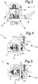
- FIG. 1 an inventive sliding system 1 for windows and doors in a variant is shown. It has a door or window opening 2, which is formed by a first vertical frame profile 3a, a second vertical frame profile 3b and an upper horizontal 4 and a lower horizontal frame profile 5.
- An outer wing 6 and an inner wing 7 each have a glass element 8, which are held firmly in the frame profiles 9, which form a casement 10.
- both wings 6, 7 horizontally against each other.
- only one wing 6, 7 is slidably mounted.
- the sliding system 1 has a plurality of magnetic seals 11. These magnetic seals 11 each have a holding magnet 12 and a movable magnetic sealing element 13.
- the magnetic seals 11 are fixed to the vertical frame profile 3 by means of plugged auxiliary frame 14.
- the subframe 14 with clips 15 and screws 16 are connected externally and by means of screws 16 inside with the frame profile 9, but it is also possible to connect using other conventional material or form-fitting connections.
- the subframe 14 has a groove 17 in which the magnetic sealing element 13 is slidably mounted.
- the magnetic sealing element 13 is biased by means of a spring element 18, which constitutes a gas-tight connecting web between magnetic sealing element 13 and groove 17, in a movement position 19.
- the movable magnetic sealing element 13 is arranged in the auxiliary frame 9 and the holding magnet 12 in the casement 10. It is also possible that the holding magnet 12 is mounted analogously to the magnetic sealing element 13 in an infected auxiliary profile on the casement 10.
- the arrangement of the magnetic seal 11 may be designed in a non-illustrated embodiment so that the holding magnet 12 is located on the non-moving frame profile 9 or subframe 14 and the magnetic sealing element 13 on the sash 10, or on the auxiliary profile 28th
- the magnetic sealing element 13 is displaceable in the groove 17 between a sealing position 20 and the movement position 19.
- the magnetic seal 11 is an active seal. That is, this is in a closed position 50 of the wing 7 in the sealing position 20 and in an open position 51 in the movement position 19th
- the displacement is accomplished by means of the magnetic attraction between the holding magnet 12 and the magnetic sealing element 13.
- a spring force of the spring element 18 outweighs the magnetic attraction, since the holding magnet 12 by the displacement of the blade 7 has no significant magnetic attraction more on the movable magnetic sealing element 13 more.
- the magnetic attraction force predominates over the spring force.
- the magnetic sealing element 13 rests with a sealing surface 21 directly on the wing 7. This results in a tight connection between the inner wing 7 and the frame profile.
- a fluid flow 22 is shown, which can not pass the magnetic seal 11.
- the magnetic seals 11 are formed continuously and integrally in this embodiment.
- the sliding system 1 of the embodiment shown has a lift-slide wing.
- the magnetic seal 11 has not only a vertical portion 22 but also a horizontal portion 23.
- the magnetic seal 11 additionally has an opening magnet 24, as in 4 and FIG. 5 shown. This is arranged next to the holding magnet 12 and provides in a raised position 52 of the blade 7 for a repulsion of the movable magnetic sealing element 13. In a lowered 53, closed position 50, the opening magnet 24 has no influence.
- an additional opening magnet 24 may be arranged analogously in an embodiment not shown, also in the vertical portion 22 to provide in an open position 51 of the inner wing 7 for horizontal displacement in a direction of displacement 25 for repulsion of the magnetic sealing element 13.
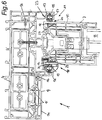
- Fig. 6 the installation situation of the opening magnet 24 is shown in more detail.
- Fig. 7 and in Fig. 8 each have a second movable magnetic sealing element 26 extending perpendicularly in the position of use. At this is on the other opposite wing 6, 7 in the closed position 50, a second holding magnet 27 at.
- an auxiliary profile 28 is attached to each wing 6, 7 at a vertically extending portion 29 of the sash.
- the plugged auxiliary profile 28 carries the second magnetic sealing element 13 and the second holding magnet 27th
- the function of the opening magnet 24 between the vertical portions 29 of the sash 10 is in the FIGS. 7 and 8 shown in detail. The function is analogous to that of the lifting-sliding mechanism.
Landscapes
- Engineering & Computer Science (AREA)
- Civil Engineering (AREA)
- Structural Engineering (AREA)
- Physics & Mathematics (AREA)
- Electromagnetism (AREA)
- Mechanical Engineering (AREA)
- Specific Sealing Or Ventilating Devices For Doors And Windows (AREA)
Abstract
Description
- Die Erfindung betrifft ein Schiebesystem für Fenster oder Türen mit einem inneren Flügel und einem äußeren Flügel, wobei mindestens ein Flügel horizontal zwischen einer geschlossenen Stellung und einer offenen Stellung verschiebbar ist und wobei die Flügel jeweils aus einem Flügelrahmen und mindestens einem Glaselement aufgebaut sind, sowie mit einem ersten vertikalen Rahmenprofil, einem zweiten vertikalen Rahmenprofil und einem horizontalen oberen Rahmenprofil, und einem horizontalen unteren Rahmenprofil, die die Tür- oder Fensteröffnung bilden, in der der Flügel horizontal verschiebbar ist, und mit mindestens einer an zumindest einem der Rahmenprofile und zumindest einem dem Rahmenprofil gegenüberliegenden Flügelrahmen befestigten magnetischen Dichtung, die ein bewegliches magnetisches Dichtelement und einen Haltemagneten aufweist, wobei das bewegliche magnetische Dichtelement in einer Nut zwischen einer Dichtstellung und einer Bewegungsstellung verschiebbar gelagert ist, und die magnetische Dichtung ein Federelement aufweist, welches das bewegliche magnetische Dichtelement in die Bewegungsstellung vorspannt.
- Dabei ist vorgesehen, dass mindestens ein Flügel horizontal zwischen einer geschlossenen Stellung und einer offenen Stellung verschiebbar ist und dass die Flügel jeweils aus einem Flügelrahmen und mindestens einem Glaselement aufgebaut sind. Ein erstes vertikales Rahmenprofil, ein zweites vertikales Rahmenprofil und ein oberes und unteres horizontales Rahmenprofil bilden die Tür- oder Fensteröffnung, in der der Flügel horizontal verschiebbar ist. Mindestens eine an einem Rahmenprofil befestigte erste magnetische Dichtung, die am Flügelrahmen des horizontal beweglichen Flügels anliegt, gleitet beim Verschieben an diesem entlang.
- Die Begriffe innerer Flügel und äußerer Flügel beziehen sich hier auf die Einbaulage, wobei es aber im Rahmen der vorliegenden Erfindung nicht wesentlich ist, welcher Flügel innen und welcher Flügel außen angeordnet ist. Die obige Unterscheidung dient primär der leichteren Erklärung der Erfindung.
- Die Abdichtung von Flügeln in Schiebesystemen ist generell problematisch. Mit Gummidichtungen kann eine sehr gute Abdichtung erzielt werden, allerdings ist der Gleit-Widerstand beim Verschieben der Flügel groß. Besonders störend ist dabei zuweilen der extrem hohe Losbrech-Widerstand, insbesondere dann, wenn ein Flügel längere Zeit nicht bewegt worden ist.
- Bürstendichtungen ermöglichen eine Verschiebung von Flügeln mit geringem Kraftaufwand, besitzen aber den Nachteil einer relativ geringen Dichtwirkung und verursachen beim Verschieben häufig unerwünschte Geräusche.
- Die oben dargestellten Probleme sind besonders im Fall von Hebe-Schiebetüren störend, bei denen ein zu verschiebender Flügel zuerst angehoben werden muss, bevor eine Verschiebung möglich ist. Beim Anheben muss in einem solchen Fall nicht nur das Gewicht des Flügels überwunden werden sondern auch der Reibungswiderstand der Dichtungen.
- Magnetische Dichtungen sind aus der
US 5 706 607 A bekannt. Dabei ist eine magnetische Dichtung in Verschieberichtung der Tür angeordnet. Ein bewegliches magnetisches Dichtelement der magnetischen Dichtung ist in einer Nut verschiebbar angeordnet und wird mittels der magnetischen Anziehungskraft zwischen dem Dichtelement und einem gegenüberliegenden Haltemagnet der magnetischen Dichtung aus der Nut gezogen. Nachteil dieser Ausführung ist, dass die Rückstellung des beweglichen magnetischen Dichtelementes nicht gewährleistet ist. Weiters fehlt die Möglichkeit zur Abdichtung der vertikalen Rahmenprofile. Darüber hinaus ist hier zu erwarten, dass Undichtigkeiten zwischen der Nut und dem beweglichen magnetischen Dichtelement auftreten. - Aus der
DE 86 13 038 U1 ist eine horizontale magnetische Dichtung in einem normalen Schiebesystem bekannt, bei der während eines Öffnungsvorgangs durchgehend das magnetische Dichtelement am Haltemagneten anliegt. - Die Dichtwirkung ist bei dieser Anordnung zwar sehr gut, jedoch kommt es durch das Schleifen des Dichtelements an einem Gegenstück während der Bewegung zur Abnutzung der magnetischen Dichtung. Weiters ist durch den ständigen Kontakt der magnetischen Dichtung mit der Dichtfläche der Widerstand gegen die Öffnungsbewegung erhöht.
- Die
US 4 006 562 A und dieDE 81 26649 U1 zeigen magnetische Dichtungen mit einem federnden Balgelement für den Einsatz bei einem Türflügel oder bei den feststehenden Seitenholmen einer Schiebetür. - Aufgabe der vorliegenden Erfindung ist es, diese Nachteile zu vermeiden und eine Lösung anzugeben, die eine leichte Verschiebbarkeit gewährleistet und die Abnutzung der Dichtelemente verringert.
- Diese Aufgabe wird dadurch gelöst, dass der horizontal bewegliche Flügel als Hebe-Schiebe-Flügel ausgebildet ist. Dadurch kann die leichte Verschiebbarkeit garantiert werden. Vor allem die horizontal angeordneten magnetischen Dichtungen des erfindungsgemäßen Schiebesystems haben einen großen Vorteil gegenüber den bekannten Dichtungen. Durch das Anheben zu Beginn wird das magnetische Dichtelement von der Dichtfläche durch die Kraft der Feder wegbewegt. Dadurch kommt es während der gesamten Bewegung des Flügels nicht zu einem Kontakt zwischen Dichtfläche und magnetischem Dichtelement. Der Widerstand ist dadurch verringert. Abnutzung oder Beschädigung der magnetischen Dichtung durch die mehrmalige Öffnung und das häufige Schließen des Schiebesystems werden verhindert.
- Bei einem Schiebesystem für Fenster und Türen dieser Bauart muss der bewegliche Flügel vor der Verschiebung zunächst angehoben werden, um in angehobenem Zustand in die geöffnete Stellung gebracht zu werden. Bei einem solchen System können die waagerechten Dichtflächen ausschließlich oder zusätzlich durch weiche Gummidichtungen abgedichtet werden, die nicht notwendigerweise als magnetische Dichtungen auszubilden sind, da das Anheben senkrecht zur Dichtebene erfolgt und danach keine Berührung mit den gegenüberliegenden Bauteil mehr auftritt. Aus diesem Grund werden solche Schiebesysteme bevorzugt für hohe Anforderungen eingesetzt.
- Um den Widerstand während der Verschiebung noch weiter zu verringern, ist es günstig, wenn der Haltemagnet in der geschlossenen Stellung von einer Dichtfläche aus gegenüber dem magnetischen Dichtelement angeordnet ist, und dass der Haltemagnet in der offenen Stellung gegenüber dem magnetischen Dichtelement versetzt ist.
- Es ist günstig, wenn das bewegliche magnetische Dichtelement einen gasdichten Verbindungssteg zur Nut aufweist, da die nunmehr vorgeschriebenen strengen Dichtheitswerte für Schiebetüren erreicht werden können und dennoch eine extreme Leichtgängigkeit bei sehr geringer Geräuschentwicklung erzielt wird, denn dieser Verbindungssteg lässt zwischen dem beweglichen magnetischen Dichtelement und der Nut keine Undichtigkeiten zu.
- Besonders vorteilhaft ist eine Ausführungsform, bei der das Federelement den Verbindungssteg bildet, denn dadurch wird die Komplexität reduziert.
- Um auch eine Dichtung für die vertikalen Rahmenprofile bereitzustellen ist es vorteilhaft, wenn die magnetische Dichtung einen vertikalen Abschnitt aufweist, der senkrecht zu einer Verschieberichtung und parallel zu einer Ebene des Flügels in zumindest einem der vertikalen Rahmenprofile angeordnet ist.
- Um eine Dichtungsmöglichkeit für das gesamte Schiebesystem bereitzustellen ist es günstig, wenn die magnetische Dichtung einen horizontalen Abschnitt aufweist, der in zumindest einem der horizontalen Rahmenprofile parallel zur Verschieberichtung angeordnet ist.
- Es ist vorteilhaft, wenn das Schiebesystem einen Öffnungsmagneten aufweist, der neben dem Haltemagneten angeordnet ist, und der das bewegliche magnetische Dichtelement abstößt. Dadurch entsteht der Effekt, dass nach begonnener Bewegung, eine weitere Bewegung weniger Kraft bedarf und beim Anheben nicht mehr das gesamte Gewicht des Flügels von der Person gehoben werden muss.
- Der gleichen Vorteile lassen sich erzielen, wenn der Öffnungsmagnet in zumindest einem der horizontalen Rahmenprofile so angeordnet ist, dass dieser in einer angehobenen Stellung des Flügels das magnetische Dichtelement abstößt und in die Bewegungsstellung verschiebt.
- In einer besonders bevorzugten Ausführungsvariante der Erfindung ist vorgesehen, dass die magnetischen Dichtungen als umlaufende Dichtungen ausgeführt sind. Auch wenn es wie oben ausgeführt theoretisch möglich ist, die waagerechten Dichtflächen mit herkömmlichen Gummidichtungen auszustatten, stellen die Eckbereiche stets Schwachpunkte der Abdichtung dar. Mit umlaufend ausgeführten magnetischen Dichtungen können diese Schwachpunkte in vorteilhafter Weise vermieden werden.
- Vorzugsweise weist ein vertikales Rahmenprofil einen aufgesteckten Hilfsrahmen auf, der die magnetische Dichtung trägt. Das Grundprofil des Rahmens kann dabei standardmäßig ausgebildet werden, so dass nur in den relevanten Bereichen ein Hilfsrahmen vorgesehen sein muss. Mit aufgesteckt soll hier jede übliche Art der form- und/ oder kraftschlüssigen Verbindung gemeint sein, wie etwa aufgeklipst, verschraubt oder dergleichen.
- In analoger Weise kann ebenso vorgesehen sein, dass das horizontale Rahmenprofil einen aufgesteckten Hilfsrahmen aufweist, der die magnetische Dichtung trägt.
- Besonders bevorzugt ist es in diesem Zusammenhang, wenn die magnetische Dichtung einstückig ausgebildet ist. Aufgrund der Tatsache, dass die magnetische Dichtung umlaufend ausgebildet ist, wird auch eine zuverlässige Abdichtung in den Eckbereichen erzielt.
- Insbesondere ist es günstig, wenn sowohl der innere als auch der äußere Flügel horizontal verschiebbar sind und dass jeder Flügel ein in Gebrauchslage senkrecht verlaufendes zweites bewegliches magnetisches Dichtelement trägt, das am jeweils anderen Flügel zumindest in der geschlossenen Stellung an einem zweiten Haltemagnet anliegt. Damit kann auch zwischen den beiden Flügeln eine zuverlässige Abdichtung erreicht werden.
- Vorzugsweise weist jeder Flügel an einem vertikal verlaufenden Abschnitt des Flügelrahmens zumindest ein aufgestecktes Hilfsprofil auf, das das zweite magnetische Dichtelement und/oder den zweiten Haltemagneten trägt.
- In der Folge wird die Erfindung anhand der in den Figuren dargestellten Ausführungsvariante näher erläutert. Es zeigen:
- Fig. 1
- ein erfindungsgemäßes Schiebesystem in einer Ausführungsvariante;
- Fig. 2
- einen teilweisen waagrechten Schnitt eines seitlichen Bereichs des Schiebesystems entsprechend der Linie I-I aus
Fig. 1 ; - Fig. 3
- eine magnetische Dichtung des Schiebesystems nach einem Detail aus
Fig. 2 ; - Fig. 4
- die magnetische Dichtung in einer Bewegungsstellung des Schiebesystems analog zu
Fig. 5 ; - Fig. 5
- die magnetische Dichtung in einer Dichtstellung des Schiebesystems nach einem Detail aus
Fig. 6 ; - Fig. 6
- einen teilweisen vertikalen Schnitt des Schiebesystems entsprechend der Linie VI - VI in
Fig. 1 ; - Fig. 7
- einen teilweisen horizontalen Schnitt des Schiebesystems in geschlossener Position entsprechend der Linie VII - VII in
Fig. 1 ; und - Fig. 8
- einen teilweisen horizontalen Schnitt des Schiebesystems in geöffneter Position analog zu
Fig. 7 . - In
Fig. 1 ist ein erfindungsgemäßes Schiebesystem 1 für Fenster und Türen in einer Ausführungsvariante gezeigt. Sie weist eine Tür- oder Fensteröffnung 2 auf, die durch ein erstes vertikales Rahmenprofil 3a, ein zweites vertikales Rahmenprofil 3b und ein oberes horizontales 4 und ein unteres horizontales Rahmenprofil 5 gebildet ist. Ein äußerer Flügel 6 und ein innerer Flügel 7 weisen jeweils ein Glaselement 8 auf, das in den Rahmenprofilen 9, die einen Flügelrahmen 10 bilden, fest gehalten werden. - In der gezeigten Ausführungsvariante sind beide Flügel 6, 7 horizontal gegeneinander verschiebbar. Allerdings ist es denkbar, dass in einer anderen Ausführungsform nur ein Flügel 6, 7 verschiebbar gelagert ist.
- Im Schnitt in
Fig. 2 sind das vertikale Rahmenprofil 3a, 3b und der innere Flügel 7 zu sehen. Dabei hat das Schiebesystem 1 mehrere magnetische Dichtungen 11. Diese magnetische Dichtungen 11 weisen je einen Haltemagneten 12 und ein bewegliches magnetisches Dichtelement 13 auf. - In der gezeigten Ausführungsform sind die magnetischen Dichtungen 11 am vertikalen Rahmenprofil 3 mithilfe von aufgesteckten Hilfsrahmen 14 fixiert. Dabei sind die Hilfsrahmen 14 mit Klipps 15 und Schrauben 16 außen und mithilfe von Schrauben 16 innen mit dem Rahmenprofil 9 verbunden, es ist aber auch eine Verbindung mithilfe von anderen üblichen stoff- oder formschlüssige Verbindungen möglich.
- Die magnetischen Dichtungen 11 werden in weiterer Folge anhand der äußeren magnetischen Dichtung 11 näher erläutert. Dabei weist der Hilfsrahmen 14 eine Nut 17 auf, in der das magnetische Dichtelement 13 verschiebbar gelagert ist. Das magnetische Dichtelement 13 ist mithilfe eines Federelementes 18, das einen gasdichten Verbindungssteg zwischen magnetischem Dichtelement 13 und Nut 17 darstellt, in eine Bewegungsstellung 19 vorgespannt.
- Das bewegliche magnetische Dichtelement 13 ist im Hilfsrahmen 9 angeordnet und der Haltemagnet 12 im Flügelrahmen 10. Es ist auch möglich, dass der Haltemagnet 12 analog zum magnetischen Dichtelement 13 in einem angesteckten Hilfsprofil am Flügelrahmen 10 montiert ist.
- Die Anordnung der magnetischen Dichtung 11 kann bei einer nicht dargestellten Ausführung so gestaltet sein, dass sich der Haltemagnet 12 am nicht bewegten Rahmenprofil 9 oder Hilfsrahmen 14 befindet und das magnetische Dichtelement 13 am Flügelrahmen 10, oder am Hilfsprofil 28.
- Das magnetische Dichtelement 13 ist in der Nut 17 zwischen einer Dichtstellung 20 und der Bewegungsstellung 19 verschiebbar. Die magnetische Dichtung 11 ist eine aktive Dichtung. Das heißt, dass sich diese in einer geschlossenen Stellung 50 des Flügels 7 in der Dichtstellung 20 befindet und in einer offenen Stellung 51 in der Bewegungsstellung 19.
- Die Verschiebung wird mithilfe der magnetischen Anziehungskraft zwischen Haltemagnet 12 und magnetischem Dichtelement 13 bewerkstelligt. In der Bewegungsstellung 19 überwiegt eine Federkraft von dem Federelement 18 gegenüber der magnetischen Anziehungskraft, da der Haltemagnet 12 durch die Verschiebung des Flügels 7 keine wesentliche magnetische Anziehungskraft mehr auf das bewegliche magnetische Dichtelement 13 mehr hat.
- In der Dichtstellung 20 überwiegt die magnetische Anziehungskraft gegenüber der Federkraft. Dabei liegt das magnetische Dichtelement 13 mit einer Dichtfläche 21 direkt am Flügel 7 an. Dadurch ergibt sich eine dichte Verbindung zwischen dem inneren Flügel 7 und dem Rahmenprofil 9.
- Die Wirkungsweise der magnetischen Dichtung 11 ist in
Fig. 3 dargestellt. Dabei ist ein Fluidstrom 22 gezeigt, der die magnetische Dichtung 11 nicht passieren kann. - Die magnetischen Dichtungen 11 sind in dieser Ausführungsvariante durchlaufend und einstückig ausgebildet.
- Das Schiebesystem 1 der gezeigten Ausführung weist einen Hebe-Schiebe-Flügel auf. Dabei weist die magnetische Dichtung 11 nicht nur einen vertikalen Abschnitt 22 auf, sondern auch einen horizontalen Abschnitt 23 auf.
- Hier weist die magnetische Dichtung 11 noch zusätzlich einen Öffnungsmagneten 24 auf, wie in
Fig. 4 und Fig. 5 gezeigt. Dieser ist neben dem Haltemagneten 12 angeordnet und sorgt in einer angehobenen Stellung 52 des Flügels 7 für eine Abstoßung des beweglichen magnetischen Dichtelementes 13. In einer abgesenkten 53, geschlossenen Stellung 50 hat der Öffnungsmagnet 24 keinen Einfluss. - Durch die Abstoßung des magnetischen Dichtelementes 13 in die Bewegungsstellung 19 kann, nach Überwindung der Kraft, die notwendig ist, um in die angehobene Stellung 52 zu kommen, der Flügel 6, 7 einfacher verschoben werden.
- Die Anordnung eines zusätzlichen Öffnungsmagneten 24 kann in einer nicht dargestellten Ausführung analog dazu, auch im vertikalen Abschnitt 22 angeordnet sein um in einer offenen Stellung 51 des inneren Flügels 7 nach horizontaler Verschiebung in eine Verschieberichtung 25 für eine Abstoßung des magnetischen Dichtelementes 13 zu sorgen.
- In
Fig. 6 ist die Einbausituation des Öffnungsmagneten 24 näher gezeigt. - In
Fig. 7 und inFig. 8 weisen der innere 7 und der äußere Flügel 8 jeweils ein in Gebrauchslage senkrecht verlaufendes zweites bewegliches magnetisches Dichtelement 26 auf. An dieses liegt am jeweils anderen gegenüberliegenden Flügel 6, 7 in der geschlossenen Stellung 50 ein zweiter Haltemagnet 27 an. - Dabei ist an jedem Flügel 6, 7 an einem senkrecht verlaufenden Abschnitt 29 des Flügelrahmens ein Hilfsprofil 28 aufgesteckt. Das aufgesteckte Hilfsprofil 28 trägt das zweite magnetische Dichtelement 13 und den zweiten Haltemagneten 27.
- Die Funktion des Öffnungsmagneten 24 zwischen den vertikalen Abschnitten 29 des Flügelrahmens 10 ist in den
Figuren 7 und 8 detailliert dargestellt. Die Funktion ist analog zu der des Hebe-Schiebe-Mechanismus.
Claims (14)
- Schiebesystem (1) für Fenster oder Türen mit einem inneren Flügel (7) und einem äußeren Flügel (6), wobei mindestens ein Flügel (6, 7) horizontal zwischen einer geschlossenen Stellung (50) und einer offenen Stellung (51) verschiebbar ist und wobei die Flügel (6, 7) jeweils aus einem Flügelrahmen (10) und mindestens einem Glaselement (8) aufgebaut sind, sowie mit einem ersten vertikalen Rahmenprofil (3a), einem zweiten vertikalen Rahmenprofil (3b) und einem horizontalen oberen Rahmenprofil (4), und einem horizontalen unteren Rahmenprofil (5), die die Tür- oder Fensteröffnung (2) bilden, in der der Flügel (6, 7) horizontal verschiebbar ist, und mit mindestens einer an zumindest einem der Rahmenprofile (3a, 3b) und zumindest einem dem Rahmenprofil (3a, 3b) gegenüberliegenden Flügelrahmen (10) befestigten magnetischen Dichtung (11), die ein bewegliches magnetisches Dichtelement (13) und einen Haltemagneten (12) aufweist, wobei das bewegliche magnetische Dichtelement (13) in einer Nut (17) zwischen einer Dichtstellung (20) und einer Bewegungsstellung (19) verschiebbar gelagert ist, und die magnetische Dichtung (11) ein Federelement (18) aufweist, welches das bewegliche magnetische Dichtelement (13) in die Bewegungsstellung (19) vorspannt, dadurch gekennzeichnet, dass der horizontal bewegliche Flügel (6, 7) als Hebe-Schiebe-Flügel ausgebildet ist.
- Schiebesystem (1) nach Anspruch 1, dadurch gekennzeichnet, dass der Haltemagnet (12) in der geschlossenen Stellung (50) von einer Dichtfläche (21) aus gegenüber dem magnetischen Dichtelement (13) angeordnet ist, und dass der Haltemagnet (12) in der offenen Stellung (51) gegenüber dem magnetischen Dichtelement (13) versetzt ist.
- Schiebesystem (1) nach Anspruch 1 oder 2, dadurch gekennzeichnet, dass das bewegliche magnetische Dichtelement (13) einen gasdichten Verbindungssteg zur Nut (17) aufweist.
- Schiebesystem (1) nach Anspruch 3, dadurch gekennzeichnet, dass das Federelement (18) den Verbindungssteg bildet.
- Schiebesystem (1) nach einem der Ansprüche 1 bis 4, dadurch gekennzeichnet, dass die magnetische Dichtung (11) einen vertikalen Abschnitt (22) aufweist, der senkrecht zu einer Verschieberichtung (25) und parallel zu einer Ebene des Flügels (29) in zumindest einem der vertikalen Rahmenprofile (3a, 3b) angeordnet ist.
- Schiebesystem (1) nach einem der Ansprüche 1 bis 5, dadurch gekennzeichnet, dass die magnetische Dichtung (11) einen horizontalen Abschnitt (23) aufweist, der in zumindest einem der horizontalen Rahmenprofile (4, 5) parallel zur Verschieberichtung (25) angeordnet ist.
- Schiebesystem (1) nach einem der Ansprüche 1 bis 6, dadurch gekennzeichnet, dass das Schiebesystem (1) einen Öffnungsmagneten (24) aufweist, der neben dem Haltemagneten (12) angeordnet ist, und der das bewegliche magnetische Dichtelement (13) abstößt.
- Schiebesystem (1) nach Anspruch 7, dadurch gekennzeichnet, dass der Öffnungsmagnet (24) in zumindest einem der horizontalen Rahmenprofile (4, 5) so angeordnet ist, dass dieser in einer angehobenen Stellung (52) des Flügels (6, 7) das magnetische Dichtelement (13) abstößt und in die Bewegungsstellung (19) verschiebt.
- Schiebesystem (1) nach einem der Ansprüche 1 bis 8, dadurch gekennzeichnet, dass die magnetische Dichtung (11) als umlaufende Dichtung ausgeführt ist.
- Schiebesystem (1) nach einem der Ansprüche 1 bis 9, dadurch gekennzeichnet, dass ein vertikales Rahmenprofil (3a, 3b) einen aufgesteckten Hilfsrahmen (14) aufweist, der die magnetische Dichtung (11) trägt.
- Schiebesystem (1) nach einem der Ansprüche 1 bis 10, dadurch gekennzeichnet, dass das horizontale Rahmenprofil (4 ,5) einen aufgesteckten Hilfsrahmen (14) aufweist, der die magnetische Dichtung (11) trägt.
- Schiebesystem (1) nach einem der Ansprüche 1 bis 11, dadurch gekennzeichnet, dass die magnetische Dichtung (11) einstückig ausgebildet ist.
- Schiebesystem (1) nach einem der Ansprüche 1 bis 12, dadurch gekennzeichnet, dass sowohl der innere (7) als auch der äußere Flügel (6) horizontal verschiebbar sind und dass jeder Flügel (6, 7) ein in Gebrauchslage senkrecht verlaufendes zweites bewegliches magnetisches Dichtelement (13) trägt, das am jeweils anderen Flügel (6, 7) zumindest in der geschlossenen Stellung (50) gegen einen zweiten Haltemagnet (27) anliegt.
- Schiebesystem (1) nach einem der Ansprüche 1 bis 13, dadurch gekennzeichnet, dass jeder Flügel (6, 7) an einem senkrecht verlaufenden Abschnitt des Flügelrahmens (10) zumindest ein aufgestecktes Hilfsprofil (28) aufweist, das das zweite magnetische Dichtelement (26) und/oder den zweiten Haltemagneten (27) trägt.
Applications Claiming Priority (1)
| Application Number | Priority Date | Filing Date | Title |
|---|---|---|---|
| ATA51078/2015A AT518105B1 (de) | 2015-12-17 | 2015-12-17 | Schiebesystem für fenster oder türen |
Publications (1)
| Publication Number | Publication Date |
|---|---|
| EP3181790A1 true EP3181790A1 (de) | 2017-06-21 |
Family
ID=57544352
Family Applications (1)
| Application Number | Title | Priority Date | Filing Date |
|---|---|---|---|
| EP16203778.2A Withdrawn EP3181790A1 (de) | 2015-12-17 | 2016-12-13 | Schiebesystem für fenster oder türen |
Country Status (2)
| Country | Link |
|---|---|
| EP (1) | EP3181790A1 (de) |
| AT (1) | AT518105B1 (de) |
Cited By (9)
| Publication number | Priority date | Publication date | Assignee | Title |
|---|---|---|---|---|
| CN107339050A (zh) * | 2017-07-11 | 2017-11-10 | 佛山市南海富轩门窗幕墙有限公司 | 三防推拉窗 |
| CN107524398A (zh) * | 2017-09-05 | 2017-12-29 | 山东南山铝业股份有限公司 | 密封机构及提升推拉门 |
| DE102017127642A1 (de) | 2017-11-23 | 2019-05-23 | Athmer Ohg | Schiebetürdichtungssystem |
| CN110130810A (zh) * | 2019-06-03 | 2019-08-16 | 杭州知天电子商务有限公司 | 一种电气柜 |
| WO2020078379A1 (zh) * | 2018-10-16 | 2020-04-23 | 清远市首一建筑新材料有限公司 | 一种磁悬浮推拉侧压门窗 |
| EP3790824A1 (de) * | 2018-05-07 | 2021-03-17 | Rite-Hite Holding Corporation | Dichtungsvorrichtung für ladebrücken |
| CN112739879A (zh) * | 2018-08-31 | 2021-04-30 | 铁箱有限公司 | 滑动支承装置 |
| US20220170548A1 (en) * | 2019-08-27 | 2022-06-02 | Phc Corporation | Seal structure of cold storage and cold storage |
| CN114753745A (zh) * | 2022-04-21 | 2022-07-15 | 浙江世纪豪门家居科技有限公司 | 一种铝合金推拉节能门窗系统 |
Families Citing this family (2)
| Publication number | Priority date | Publication date | Assignee | Title |
|---|---|---|---|---|
| DE202019102317U1 (de) * | 2019-04-25 | 2020-07-29 | Raico Bautechnik Gmbh | Hebe-Schiebe-Tür oder Hebe-Schiebe-Fenster |
| DE102021106832A1 (de) | 2021-03-19 | 2022-09-22 | SCHÜCO International KG | Schiebewand mit dichtungsanordnung |
Citations (3)
| Publication number | Priority date | Publication date | Assignee | Title |
|---|---|---|---|---|
| CH580219A5 (en) * | 1972-12-27 | 1976-09-30 | Plastik Bauelemente Ag | Hollow member for window frame - sealing strips for glass and retaining member fit into channels formed between ribs |
| DE3200497A1 (de) * | 1982-01-09 | 1983-07-21 | Hans Kühl Metallbau GmbH & Co KG, 4630 Bochum | Schiebetueranlage |
| DE8613038U1 (de) * | 1985-05-17 | 1986-08-21 | Ilpea S.p.A., Malgesso, Varese | Dichtung für Türen und Fenster, die in Schließstellung zwischen den Außen- und den Innenteilen der Tür bzw. des Fensters eine Abdichtung bewirkt |
Family Cites Families (2)
| Publication number | Priority date | Publication date | Assignee | Title |
|---|---|---|---|---|
| US4006562A (en) * | 1976-01-02 | 1977-02-08 | The Stanley Works | Door system with improved weatherseal |
| DE8126649U1 (de) * | 1981-09-12 | 1982-01-14 | Hüppe Duscha GmbH, 2900 Oldenburg | Magnetleistenverschluss insbesondere fuer duschabtrennungs-schiebetueren |
-
2015
- 2015-12-17 AT ATA51078/2015A patent/AT518105B1/de not_active IP Right Cessation
-
2016
- 2016-12-13 EP EP16203778.2A patent/EP3181790A1/de not_active Withdrawn
Patent Citations (3)
| Publication number | Priority date | Publication date | Assignee | Title |
|---|---|---|---|---|
| CH580219A5 (en) * | 1972-12-27 | 1976-09-30 | Plastik Bauelemente Ag | Hollow member for window frame - sealing strips for glass and retaining member fit into channels formed between ribs |
| DE3200497A1 (de) * | 1982-01-09 | 1983-07-21 | Hans Kühl Metallbau GmbH & Co KG, 4630 Bochum | Schiebetueranlage |
| DE8613038U1 (de) * | 1985-05-17 | 1986-08-21 | Ilpea S.p.A., Malgesso, Varese | Dichtung für Türen und Fenster, die in Schließstellung zwischen den Außen- und den Innenteilen der Tür bzw. des Fensters eine Abdichtung bewirkt |
Cited By (10)
| Publication number | Priority date | Publication date | Assignee | Title |
|---|---|---|---|---|
| CN107339050A (zh) * | 2017-07-11 | 2017-11-10 | 佛山市南海富轩门窗幕墙有限公司 | 三防推拉窗 |
| CN107524398A (zh) * | 2017-09-05 | 2017-12-29 | 山东南山铝业股份有限公司 | 密封机构及提升推拉门 |
| DE102017127642A1 (de) | 2017-11-23 | 2019-05-23 | Athmer Ohg | Schiebetürdichtungssystem |
| EP3790824A1 (de) * | 2018-05-07 | 2021-03-17 | Rite-Hite Holding Corporation | Dichtungsvorrichtung für ladebrücken |
| CN112739879A (zh) * | 2018-08-31 | 2021-04-30 | 铁箱有限公司 | 滑动支承装置 |
| WO2020078379A1 (zh) * | 2018-10-16 | 2020-04-23 | 清远市首一建筑新材料有限公司 | 一种磁悬浮推拉侧压门窗 |
| CN110130810A (zh) * | 2019-06-03 | 2019-08-16 | 杭州知天电子商务有限公司 | 一种电气柜 |
| US20220170548A1 (en) * | 2019-08-27 | 2022-06-02 | Phc Corporation | Seal structure of cold storage and cold storage |
| US12018755B2 (en) * | 2019-08-27 | 2024-06-25 | Phc Corporation | Seal structure of cold storage and cold storage |
| CN114753745A (zh) * | 2022-04-21 | 2022-07-15 | 浙江世纪豪门家居科技有限公司 | 一种铝合金推拉节能门窗系统 |
Also Published As
| Publication number | Publication date |
|---|---|
| AT518105A1 (de) | 2017-07-15 |
| AT518105B1 (de) | 2017-10-15 |
Similar Documents
| Publication | Publication Date | Title |
|---|---|---|
| AT518105B1 (de) | Schiebesystem für fenster oder türen | |
| EP3259428B1 (de) | Dichtungsvorrichtung für fenster- und türelemente | |
| DE102017117573B4 (de) | Anordnung einer Dichtungsvorrichtung sowie damit versehene Schiebetür | |
| DE102017101555A1 (de) | Hubschwelle | |
| DE102006007672A1 (de) | Dichtungsanordnung eines Fensters, einer Tür oder dgl. | |
| EP2957699B1 (de) | Montagehilfe für ein Fenster | |
| EP2402545B1 (de) | Schiebetüranlage | |
| EP3728778B1 (de) | Türflügel mit dichtungssystem | |
| EP2672046A2 (de) | Führungsschienenanordnung | |
| EP3371402B1 (de) | Beschlaganordnung für ein hebe-schiebe-element mit rahmenseitigem verstellelement | |
| EP2960421B1 (de) | Schiebetürsystem | |
| EP3064698A1 (de) | Tor | |
| EP2979951B1 (de) | Schiebetür mit abgedichteter führungsschiene | |
| EP3543451B1 (de) | Mittelverschlusseinheit für einen hebe-schiebetür-flügel | |
| DE2525837A1 (de) | Schiebetuere mit steuerelementen zum andruecken der schiebetuere an einen blendrahmen oder dergleichen | |
| DE10235301A1 (de) | Faltanlage | |
| EP3730730A1 (de) | Hebe-schiebe-tür oder hebe-schiebe-fenster | |
| DE202016008096U1 (de) | Gebäudeabschlussantriebsvorrichtung | |
| AT11890U1 (de) | Fensterelement | |
| DE102015102582B3 (de) | Vorsatztür oder -fenster, insbesondere Insektenschutztür oder -fenster | |
| DE202021105732U1 (de) | Sicherheitsfenster | |
| EP2861811B1 (de) | Fenster, tür oder dergleichen, mit einer verschlussleiste | |
| DE102010030785B4 (de) | Schiebetüranlage | |
| EP2261453B1 (de) | Fenster oder Tür | |
| DE102015011292A1 (de) | Kupplungsvorrichtung für Hebe-Schiebe-Türen oder -Fenster und Verfahren |
Legal Events
| Date | Code | Title | Description |
|---|---|---|---|
| PUAI | Public reference made under article 153(3) epc to a published international application that has entered the european phase |
Free format text: ORIGINAL CODE: 0009012 |
|
| AK | Designated contracting states |
Kind code of ref document: A1 Designated state(s): AL AT BE BG CH CY CZ DE DK EE ES FI FR GB GR HR HU IE IS IT LI LT LU LV MC MK MT NL NO PL PT RO RS SE SI SK SM TR |
|
| AX | Request for extension of the european patent |
Extension state: BA ME |
|
| 17P | Request for examination filed |
Effective date: 20171218 |
|
| RBV | Designated contracting states (corrected) |
Designated state(s): AL AT BE BG CH CY CZ DE DK EE ES FI FR GB GR HR HU IE IS IT LI LT LU LV MC MK MT NL NO PL PT RO RS SE SI SK SM TR |
|
| 17Q | First examination report despatched |
Effective date: 20190628 |
|
| RIC1 | Information provided on ipc code assigned before grant |
Ipc: E05D 15/56 20060101ALI20191219BHEP Ipc: E06B 7/215 20060101ALI20191219BHEP Ipc: E06B 7/20 20060101AFI20191219BHEP Ipc: E06B 3/52 20060101ALI20191219BHEP |
|
| STAA | Information on the status of an ep patent application or granted ep patent |
Free format text: STATUS: THE APPLICATION IS DEEMED TO BE WITHDRAWN |
|
| 18D | Application deemed to be withdrawn |
Effective date: 20200701 |