EP3178604B1 - Vorrichtung zum beschleifen der innenseiten der wulstbereiche von fahrzeugluftreifen - Google Patents
Vorrichtung zum beschleifen der innenseiten der wulstbereiche von fahrzeugluftreifen Download PDFInfo
- Publication number
- EP3178604B1 EP3178604B1 EP16186505.0A EP16186505A EP3178604B1 EP 3178604 B1 EP3178604 B1 EP 3178604B1 EP 16186505 A EP16186505 A EP 16186505A EP 3178604 B1 EP3178604 B1 EP 3178604B1
- Authority
- EP
- European Patent Office
- Prior art keywords
- grinding
- pneumatic vehicle
- vehicle tyre
- tire
- tyre
- Prior art date
- Legal status (The legal status is an assumption and is not a legal conclusion. Google has not performed a legal analysis and makes no representation as to the accuracy of the status listed.)
- Active
Links
Images

Classifications
-
- B—PERFORMING OPERATIONS; TRANSPORTING
- B29—WORKING OF PLASTICS; WORKING OF SUBSTANCES IN A PLASTIC STATE IN GENERAL
- B29D—PRODUCING PARTICULAR ARTICLES FROM PLASTICS OR FROM SUBSTANCES IN A PLASTIC STATE
- B29D30/00—Producing pneumatic or solid tyres or parts thereof
- B29D30/06—Pneumatic tyres or parts thereof (e.g. produced by casting, moulding, compression moulding, injection moulding, centrifugal casting)
- B29D30/0601—Vulcanising tyres; Vulcanising presses for tyres
- B29D30/0633—After-treatment specially adapted for vulcanising tyres
-
- B—PERFORMING OPERATIONS; TRANSPORTING
- B24—GRINDING; POLISHING
- B24B—MACHINES, DEVICES, OR PROCESSES FOR GRINDING OR POLISHING; DRESSING OR CONDITIONING OF ABRADING SURFACES; FEEDING OF GRINDING, POLISHING, OR LAPPING AGENTS
- B24B19/00—Single-purpose machines or devices for particular grinding operations not covered by any other main group
- B24B19/26—Single-purpose machines or devices for particular grinding operations not covered by any other main group for grinding workpieces with arcuate surfaces, e.g. parts of car bodies, bumpers or magnetic recording heads
-
- B—PERFORMING OPERATIONS; TRANSPORTING
- B24—GRINDING; POLISHING
- B24B—MACHINES, DEVICES, OR PROCESSES FOR GRINDING OR POLISHING; DRESSING OR CONDITIONING OF ABRADING SURFACES; FEEDING OF GRINDING, POLISHING, OR LAPPING AGENTS
- B24B5/00—Machines or devices designed for grinding surfaces of revolution on work, including those which also grind adjacent plane surfaces; Accessories therefor
- B24B5/18—Machines or devices designed for grinding surfaces of revolution on work, including those which also grind adjacent plane surfaces; Accessories therefor involving centreless means for supporting, guiding, floating or rotating work
- B24B5/185—Machines or devices designed for grinding surfaces of revolution on work, including those which also grind adjacent plane surfaces; Accessories therefor involving centreless means for supporting, guiding, floating or rotating work for internal surfaces
-
- B—PERFORMING OPERATIONS; TRANSPORTING
- B24—GRINDING; POLISHING
- B24B—MACHINES, DEVICES, OR PROCESSES FOR GRINDING OR POLISHING; DRESSING OR CONDITIONING OF ABRADING SURFACES; FEEDING OF GRINDING, POLISHING, OR LAPPING AGENTS
- B24B5/00—Machines or devices designed for grinding surfaces of revolution on work, including those which also grind adjacent plane surfaces; Accessories therefor
- B24B5/36—Single-purpose machines or devices
- B24B5/366—Single-purpose machines or devices for grinding tyres
Definitions
- Such a sealing tape consists of a rubber ring with an integrated tire valve, sits on the cylindrical part of the rim between the two tire beads and is supported on the inside of the tire beads.
- the most important advantage of the sealing tape compared to the system with hose and flap is that that the risk of a sudden loss of pressure in the event of a breakdown is extremely unlikely.
- For a seat of the sealing tape that seals the interior of the tire it is necessary that the elevations or unevenness produced during vulcanization on the inside of the bead areas - the contact surfaces of the sealing tape - be removed by grinding. Up to now it has been customary to grind these unevenness by hand using a hand grinder of conventional design.
- a device of the type mentioned is for example from EP 1 839 913 A2 known.
- This device is primarily intended to grind the inner surface of a pneumatic vehicle tire in order to prepare the tire for the application of a stain in such a way that the tire can be equipped with various electronic devices, for example.
- the device enables the grinding depth provided for the application of stains to be set precisely and allows adaptation to different tire sizes and types.
- a device of the type mentioned is also known in which the inner surface of a pneumatic vehicle tire is ground together with a mold release agent to level out the surface.
- the device has a frame structure on which a swivel element provided with a grinding wheel is adjustably arranged.
- a mechanism that is rotatable with respect to the grinding wheel is also attached to the frame structure in order to hold the vehicle tire and to rotate it at a specific peripheral speed.
- the international registration document WO 2013/048464 A1 discloses an apparatus for deforming and supporting the sidewall of a tire to mount components on the inside of the tire.
- the DE 10 2012 111 454 A1 discloses an apparatus for machine-buffing the surface of a solid rubber tire. The tire is held in rotation by a tensioning device. The tensioning device holds and fixes the tire only on one side on a partial area of the tire floor, with a machine-driven, rotating buffing unit provided with a buffing head that can be positioned on the tire floor and variably adjusted in all spatial directions.
- a bead grinding device for reducing the eccentricity between the center of the outer contour of a pneumatic vehicle tire and the center of the bead contour by grinding the bead by means of a grinding head over a sector of up to preferably 40 °.
- the grinding head is arranged on a grinding arm that can be moved along the bead and carries a motor-driven grinding stone.
- a clamping device is provided which grips and fixes the tire on the inside of the bead to be ground.
- the invention is based on the object of providing a device by means of which the grinding process can be carried out in a simpler and more rational manner and as precisely as possible.
- the device has a vertical support plate, adjustable parallel to the tire axis of the positioned pneumatic vehicle tire, against which the pneumatic vehicle tire is pressed by the grinding unit and which is designed with low friction on its side facing the pneumatic vehicle tire.
- the device according to the invention allows a defined grinding of the inside of the bead areas in a rational way.
- the tire is held by the grinding unit and at the same time pressed against the vertical support plate which is adjustable parallel to the tire axis of the positioned pneumatic vehicle tire and which is designed with low friction on its side facing the pneumatic vehicle tire.
- the support plate can be provided with a plurality of omnidirectional rollers on its side facing the pneumatic vehicle tire according to a further feature.
- the device for rotating the pneumatic vehicle tire sets the pneumatic vehicle tire in rotary motion from the outside during the grinding.
- This device has a plurality of, in particular two, rollers which can be set in rotary motion and on which the pneumatic vehicle tire is positioned axially parallel.
- the grinding unit in addition to the motor-driven grinding cylinder, has two free-running rollers on its holder in an axially parallel alignment to the axis of rotation of the grinding cylinder, one of which is arranged in the grinding direction in front of the grinding cylinder, the other behind the grinding cylinder.
- the leading roller has the function of a guide roller and is arranged on the holder in such a way that it tangentially contacts the area to be ground.
- the second, trailing roller determines the grinding depth and is arranged on the holder in such a way that it contacts the area that has already been ground and is therefore offset by the mentioned grinding depth compared to the other roller. Both roles are advantageously mounted elastically on the bracket.
- the grinding unit also has a further roller on its holder, namely a free-running pressure roller, the axis of rotation of which runs parallel to the tire axis when the grinding cylinder is perpendicular.
- a further roller on its holder, namely a free-running pressure roller, the axis of rotation of which runs parallel to the tire axis when the grinding cylinder is perpendicular.
- the pressure roller is brought into contact with the bead seat surface of the bead area and also has a holding function.
- the outer surface of the pressure roller is advantageously curved in a concave manner, so that the roller can be well supported on the tire bead in the required different positions of the grinding unit during the grinding process.
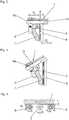
- Fig. 1 shows the device according to the invention has a frame 10, on which a horizontal positioning device 11 is arranged with preferably two motor-driven rollers 12, which run parallel to one another and on which a pneumatic vehicle tire can be positioned upright with its axis of rotation parallel to the rollers 12 .
- a horizontal positioning device 11 is arranged with preferably two motor-driven rollers 12, which run parallel to one another and on which a pneumatic vehicle tire can be positioned upright with its axis of rotation parallel to the rollers 12 .
- the rollers 12 are driven, the pneumatic vehicle tire is set in rotary motion.
- Another component of the device is a grinding unit 1 for grinding the insides of the bead areas of the pneumatic vehicle tire, the grinding unit 1, as will be described below, pressing the pneumatic vehicle tire to be ground against a support plate 8 arranged vertically on the frame 10 during a grinding process.
- the grinding unit 1 has a holder 1a on which a grinding cylinder 2 is rotatably mounted, which is coated with granular material and can be set in rotary motion about its cylinder axis by means of an electric drive (not shown).
- a grinding cylinder 2 is rotatably mounted, which is coated with granular material and can be set in rotary motion about its cylinder axis by means of an electric drive (not shown).
- the starting position of the grinding unit 1 shown the cylinder axis of the grinding cylinder 2 runs in the vertical direction.
- the holder 1a and therefore also the grinding cylinder 2 are mounted adjustable and movable in the vertical direction (double arrow P 1 ) and in the horizontal direction - axially to the pneumatic vehicle tire (double arrow P 2 ) and by means of an inclination adjustment device, which is not shown in detail, in the direction Inside of the tire mold can be tilted.
- the “tilt angle" with respect to a vertical is preferably up to 30 °.
- the adjustment options of inclination, The height and horizontal position allow the grinding cylinder 2 to be brought into the required position and to be aligned tangentially to the inside of the contacting tire bead.
- the grinding unit 1 further comprises two free-running rollers 4, 5, the axes of which run parallel to the axis of the grinding cylinder 2, which are rotatably mounted on the holder 1a and opposite the holder 1a in the direction of the double arrow P 3 in Fig. 4 are adjustable, so that they can be placed tangentially on the inside of the tire bead while maintaining the parallelism of the axes, one free roller 4 leading the grinding cylinder 2 and the other roller 5 following the grinding cylinder 2.
- the rollers 4, 5 are adjustable, the roller 4 tangentially contacting the tire in the same plane as the grinding cylinder 2, the roller 5 offset by the grinding depth t, as in FIG Fig. 4 shown.
- the pressure roller 6 has an outwardly and thus concavely curved outer surface 6a.
- a bead area 7 of a pneumatic vehicle tire is also shown schematically in FIG Fig. 4 a cross-section of a short longitudinal section of the bead area 7.
- the pneumatic vehicle tire To operate the device, the pneumatic vehicle tire, the bead areas 7 of which are to be ground on the inside, is placed upright on the rollers 12 of the positioning device 11.
- the support plate 8 On the back of the tire is the support plate 8, the position of which in the direction of the double arrow P 4 in Fig. 2 is adjustable in order to position pneumatic vehicle tires of different widths relative to the inclination adjustment device.
- the support plate 8 is interrupted or open in the middle in order to be able to position the grinding device 1 inside the tire.
- the pneumatic vehicle tire is pressed against the support plate 8 by the grinding unit 1 or the grinding cylinder 2. So that the friction between the support plate 8 and the side wall of the pneumatic vehicle tire is as low as possible, the support plate 8 is provided with a plurality of omnidirectional rollers 9, for example ball rollers, on which the pneumatic vehicle tire can run almost without friction.
- the grinding unit 1 is driven into the pneumatic vehicle tire, lowered and retracted until the grinding cylinder 2 and the leading free-wheeling roller 4 come into contact with the inside of that bead area 7, the pressure roller 6 making contact with the tire bead from above.
- the grinding cylinder 2 is put into operation and at the same time the tire is also set in a rotary motion.
- the trailing free-running roller 5 is positioned at the desired grinding depth 1 and determines the grinding depth 1. After a complete rotation of the tire, that area of the inside of the bead that immediately adjoins the bead toe is sanded over a certain width.
- the structures formed by the bladder during the vulcanization of the tire are ground off in this area.
- the grinding unit 1 is tilted at the required angle, the grinding cylinder 2 being aligned tangentially to the inside of the bead area 7.
- This area of the inside of the bead, which is covered by the grinding cylinder 2 is now also ground in an analogous manner as described.
- the second bead area of the pneumatic vehicle tire is processed in an analogous manner after the pneumatic vehicle tire has been turned around and repositioned. Flawlessly smooth inner bead surfaces are necessary in order to be able to tightly position a so-called "tire sealing ring" in the pneumatic vehicle tire.
- Such sealing rings enable tubeless industrial tires to be fitted onto standard industrial tire rims which, due to their construction, normally require a tube and a flap.
- the tire sealing ring consists of a rubber ring with an integrated tire valve. This rubber ring sits on the cylindrical part of the rim, between the two tire beads, and ensures the airtight seal of the air chamber in the tire without a tube or bead tape.
- the device according to the invention can have two grinding units in the embodiment according to the invention, so that both bead areas of the tire can be ground at the same time.
Landscapes
- Engineering & Computer Science (AREA)
- Mechanical Engineering (AREA)
- Tyre Moulding (AREA)
Description
- Die Erfindung betrifft eine Vorrichtung zum Beschleifen der Innenseiten der Wulstbereiche von Fahrzeugluftreifen mit
- einer Positioniereinrichtung zum Positionieren des Fahrzeugluftreifens in aufrechter Lage mit einer Einrichtung zum Drehen des Fahrzeugluftreifens,
- einer Schleifeinheit, welche in horizontaler und vertikaler Richtung verstellbar und verfahrbar ist und mittels einer Neigungsverstelleinrichtung in Richtung des Inneren des Reifentorus kippbar ist,
- einem an der Schleifeinheit angeordneten, motorisch antreibbaren Schleifzylinder, dessen Außenfläche durch Verstellen der Schleifeinheit tangential zur Innenseite des Wulstbereiches ausrichtbar ist.
- Es ist üblich, bei der Vulkanisation von Rohreifen in Heizpressen in das Innere des Rohreifens einen Heizbalg einzubringen, welcher den Gegendruck beim Vulkanisationsprozess erzeugt und somit ermöglicht, dass der Reifen in seiner Kontur gehalten wird. Infolge ihres Aufbaus erzeugen Heizbälge an der Innenseite des vulkanisierten Fahrzeugluftreifens umlaufende oder netzstrukturartig verlaufende Erhebungen, die an und für sich nicht störend sind. Soll der Fahrzeugluftreifen mit einem Dichtband verwendet werden, sind glatte Wulstinnenseiten erforderlich. Dichtbänder ermöglichen das Aufziehen schlauchloser Industriereifen auf Standard-Industriereifenfelgen, die normalerweise aufgrund ihres Aufbaus einen Schlauch und ein Wulstband erfordern. Ein solches Dichtband besteht aus einem Gummiring mit einem integrierten Reifenventil, sitzt auf dem zylindrischen Teil der Felge zwischen den beiden Reifenwülsten und stützt sich an den Innenseiten der Reifenwülste ab. Der wichtigste Vorteil des Dichtbandes gegenüber dem System mit Schlauch und Wulstband besteht darin, dass das Risiko einen plötzlichen Druckverlustes im Pannenfall äußerst unwahrscheinlich wird. Für einen den Innenraum des Reifens abdichtenden Sitz des Dichtbandes ist es erforderlich, dass die bei der Vulkanisation an der Innenseite der Wulstbereiche - der Kontaktflächen des Dichtbandes - entstandenen Erhebungen bzw. Unebenheiten durch Schleifen entfernt werden. Bislang ist es üblich, diese Unebenheiten von Hand aus mittels einer Handschleifmaschine herkömmlicher Bauart abzuschleifen.
- Eine Vorrichtung der eingangs genannten Art ist beispielsweise aus der
EP 1 839 913 A2 bekannt. Diese Vorrichtung ist vorrangig dafür vorgesehen, die innere Oberfläche eines Fahrzeugluftreifens zu schleifen, um derart den Reifen zum Aufbringen eines Fleckens vorzubereiten, sodass der Reifen beispielsweise mit verschiedenen elektronischen Vorrichtungen ausgestattet werden kann. Die Vorrichtung ermöglicht, die zum Fleckenauftrag vorgesehene Schleiftiefe genau einzustellen und gestattet eine Anpassung an unterschiedliche Reifengrößen und Reifentypen. Aus derUS 3,953,952 B ist ebenfalls eine Vorrichtung der eingangs genannten Art bekannt, bei der die innere Oberfläche eines Fahrzeugluftreifens zusammen mit einem Formtrennmittel zum Ausgleichen der Oberfläche geschliffen wird. Die Vorrichtung weist eine Rahmenstruktur auf, an welcher ein mit einem Schleifrad versehenes Schwenkelement verstellbar angeordnet ist. An der Rahmenstruktur ist ferner ein gegenüber dem Schleifrad drehbarer Mechanismus angebracht, um den Fahrzeugreifen zu halten und mit einer bestimmten Umfangsgeschwindigkeit zu drehen. Die internationale AnmeldeschriftWO 2013/048464 A1 offenbart eine Vorrichtung zum Verformen und Stützen der Seitenwand eines Reifens um Komponenten auf der Reifeninnenseite anzubringen. DieDE 10 2012 111 454 A1 offenbart eine Vorrichtung zum maschinellen Abrauen der Oberfläche eines Vollgummireifens. Der Reifen wird von einer Spanneinrichtung gehalten in Drehbewegung versetzt. Die Spanneinrichtung hält und fixiert den Reifen lediglich einseitig an einem Teilbereich des Reifenbodens, wobei ein maschinell drehend angetriebenes Rauaggregat vorgesehen ist, welches mit einem Raukopf versehen ist, welcher am Reifenboden positionierbar ist und in allen Raumrichtungen variabel verstellbar ist. Aus derDE 10 2008 026 964 A1 ist eine Wulstschleifvorrichtung zum Verringern der Exzentrizität zwischen dem Mittelpunkt der Außenkontur eines Fahrzeugluftreifens und dem Mittelpunkt der Wulstkontur durch Abschleifen des Wulstes mittels eines Schleifkopfes über einen Sektor von bis zu vorzugsweise 40° bekannt. Der Schleifkopf ist auf einem entlang des Wulstes bewegbaren Schleifarm angeordnet und trägt einen motorisch antreibbaren Schleifstein. Des Weiteren ist eine den Reifen an der Innenseite des zu schleifenden Wulstes erfassende und fixierende Spanneinrichtung vorgesehen. - Der Erfindung liegt nun die Aufgabe zu Grunde, eine Vorrichtung zur Verfügung zu stellen, mittels welcher der Abschleifvorgang auf einfachere und rationellere Weise und möglichst exakt durchführbar ist.
- Gelöst wird die gestellte Aufgabe erfindungsgemäß dadurch, dass die Vorrichtung eine senkrecht stehende, parallel zur Reifenachse des positionierten Fahrzeugluftreifens verstellbare Stützplatte aufweist, gegen welche der Fahrzeugluftreifen von der Schleifeinheit gedrückt wird und welche an ihrer dem Fahrzeugluftreifen zugewandten Seite reibungsarm ausgeführt ist.
- Die erfindungsgemäße Vorrichtung gestattet ein definiertes Abschleifen der Innenseiten der Wulstbereiche auf rationelle Weise.
- Während des Schleifvorganges wird der Reifen von der Schleifeinheit gehalten und gleichzeitig gegen die senkrecht stehende, parallel zur Reifenachse des positionierten Fahrzeugluftreifens verstellbare Stützplatte gedrückt, welche an ihrer dem Fahrzeugluftreifen zugewandten Seite reibungsarm ausgeführt ist. Zu diesem Zweck kann die Stützplatte an ihrer dem Fahrzeugluftreifen zugewandten Seite gemäß einem weiteren Merkmal mit einer Vielzahl von Allseitenrollen versehen sein.
- Bei einer weiteren bevorzugten Ausführungsform der Vorrichtung ist vorgesehen, dass die Einrichtung zum Drehen des Fahrzeugluftreifens während des Abschleifens den Fahrzeugluftreifen von außen in Drehbewegung versetzt. Besonders bevorzugt ist eine Ausführung, bei der diese Einrichtung mehrere, insbesondere zwei in Drehbewegung versetzbare Rollen aufweist, auf welchen der Fahrzeugluftreifen achsparallel positioniert wird.
- Die Schleifeinheit weist gemäß einer weiteren, vorteilhaften Ausführungsvariante der Erfindung neben dem motorisch antreibbaren Schleifzylinder an ihrer Halterung in achsparalleler Ausrichtung zur Drehachse des Schleifzylinders zwei freilaufende Rollen auf, von welchen die eine in Schleifrichtung vor dem Schleifzylinder, die andere hinter dem Schleifzylinder angeordnet ist. Die vorlaufende Rolle hat dabei die Funktion einer Führungsrolle und ist derart an der Halterung angeordnet, dass sie den zu schleifenden Bereich tangential kontaktiert.
- Die zweite, nachlaufende Rolle bestimmt die Schleiftiefe und ist derart an der Halterung angeordnet, dass sie den bereits geschliffenen Bereich kontaktiert und daher gegenüber der anderen Rolle um die erwähnte Schleiftiefe versetzt ist. Beide Rollen sind vorteilhafterweise an der Halterung elastisch gelagert.
- Die Schleifeinheit weist ferner erfindungsgemäß an ihrer Halterung eine weitere Rolle, nämlich eine freilaufende Andrückrolle auf, deren Drehachse bei senkrechter Ausrichtung des Schleifzylinders parallel zur Reifenachse verläuft. Die Andrückrolle wird beim Schleifvorgang mit der Wulstsitzfläche des Wulstbereiches in Kontaktgebracht und übt ebenfalls eine Haltefunktion aus. Die Außenfläche der Andrückrolle ist vorteilhafterweise konkav gebogen, sodass sich die Rolle in den erforderlichen unterschiedlichen Positionen der Schleifeinheit während des Schleifvorganges am Reifenwulst gut abstützen kann.
- Weitere Merkmale, Vorteile und Einzelheiten der Erfindung werden nun anhand der schematischen Zeichnung, die ein Ausführungsbeispiel darstellt, näher beschrieben. Dabei zeigen
-
Fig. 1 eine Ansicht einer erfindungsgemäßen Vorrichtung, -
Fig. 2 eine Ansicht einer Schleifeinheit der erfindungsgemäßen Vorrichtung im Betrieb in einer möglichen Stellung, -
Fig. 3 eine Ansicht der Schleifeinheit analog zuFig. 2 , jedoch in einer anderen Stellung während des Betriebes und -
Fig. 4 eine Schnittdarstellung (Querschnitt) durch Bestandteile der Schleifeinheit im Betrieb. - In der nachfolgenden Beschreibung beziehen sich Begriffe wie "senkrecht", "waagrecht", "oben" und "unten" auf die Darstellungen in den Figuren.
- Wie
Fig. 1 zeigt weist die erfindungsgemäße Vorrichtung ein Gestell 10, auf, an welchem eine waagrechte Positioniereinrichtung 11 mit vorzugsweise zwei motorisch antreibbaren Rollen 12 angeordnet ist, die parallel zueinander verlaufen und auf welchen ein Fahrzeugluftreifen aufrecht stehend, mit seiner Drehachse parallel zu den Rollen 12, positionierbar ist. Bei angetriebenen Rollen 12 wird der Fahrzeugluftreifen in Drehbewegung versetzt. Ein weiterer Bestandteil der Vorrichtung ist eine Schleifeinheit 1 zum Abschleifen der Innenseiten der Wulstbereiche des Fahrzeugluftreifens, wobei die Schleifeinheit 1, wie noch beschrieben wird, den zu beschleifenden Fahrzeugluftreifen während eines Schleifvorganges gegen eine am Gestell 10 senkrecht angeordnete Stützplatte 8 drückt. - Die Schleifeinheit 1 weist eine Halterung 1a auf, an welcher ein Schleifzylinder 2 drehbar gelagert ist, welcher mit körnigem Material beschichtet ist und mittels eines nicht dargestellten elektrischen Antriebes um seine Zylinderachse in Drehbewegung versetzbar ist. In der in
Fig. 1 gezeigten Ausgangslage der Schleifeinheit 1 verläuft die Zylinderachse des Schleifzylinders 2 in vertikaler Richtung. Die Halterung 1a und daher auch der Schleifzylinder 2 sind in vertikaler Richtung (Doppelpfeil P1) und in horizontaler Richtung - axial zum Fahrzeugluftreifen (Doppelpfeil P2) - verstellbar und verfahrbar gelagert und mittels einer Neigungsverstelleinrichtung, die im Detail nicht dargestellt ist, in Richtung Inneres der Reifenform kippbar.Fig. 1 zeigt beispielhaft zwei Betätigungsarme 13 einer von Hand einstellbaren Neigungsverstelleinrichtung. Der "Kippwinkel" gegenüber einer Senkrechten beträgt vorzugsweise bis zu 30°. Die Verstellmöglichkeiten von Neigung, Höhe und horizontaler Lage gestatten es, den Schleifzylinder 2 in die erforderliche Position zu bringen und tangential zur Innenseite des kontaktierenden Reifenwulstes auszurichten. - Wie
Fig. 4 zeigt, umfasst die Schleifeinheit 1 ferner zwei Freilaufrollen 4, 5, deren Achsen parallel zur Achse des Schleifzylinders 2 verlaufen, welche an der Halterung 1a drehbar gelagert sind und gegenüber der Halterung 1a in Richtung des Doppelpfeiles P3 inFig. 4 verstellbar sind, sodass sie unter Beibehalten der Parallelität der Achsen an der Innenseite des Reifenwulstes tangential anlegbar sind, wobei die eine Freilaufrolle 4 dem Schleifzylinder 2 vorläuft und die andere Rolle 5 dem Schleifzylinder 2 nachläuft. Die Rollen 4, 5 sind einstellbar gelagert, wobei die Rolle 4 den Reifen in der gleichen Ebene tangential kontaktiert wie der Schleifzylinders 2, die Rolle 5 um die Schleiftiefe t versetzt, wie inFig. 4 gezeigt. An der Halterung 1a ist ferner innenseitig des Schleifzylinders 2 und gegenüber diesem nach oben versetzt eine Andrückrolle 6, ebenfalls eine Freilaufrolle, drehbar gelagert, deren Drehachse im rechten Winkel zur Drehachse des Schleifzylinders 2 und in der inFig. 1 gezeigten Betriebsstellung parallel zur Reifenachse verläuft. Die Andrückrolle 6 weist eine nach außen und somit konkav gebogene Außenfläche 6a auf. InFig. 2 und Fig. 3 ist ferner schematisch ein Wulstbereich 7 eines Fahrzeugluftreifens eingezeichnet, inFig. 4 ein Querschnitt ein kurzer Längsabschnitt des Wulstbereiches 7. - Zum Betrieb der Vorrichtung wird der Fahrzeugluftreifen, dessen Wulstbereiche 7 innenseitig geschliffen werden sollen, aufrecht stehend auf die Rollen 12 der Positioniereinrichtung 11 gestellt. An der Rückseite des Reifens befindet sich die Stützplatte 8, deren Lage in Richtung des Doppelpfeils P4 in
Fig. 2 verstellbar ist, um unterschiedlich breite Fahrzeugluftreifen gegenüber der Neigungsverstelleinrichtung zu positionieren. Die Stützplatte 8 ist mittig unterbrochen bzw. offen, um die Schleifeinrichtung 1 im Reifeninneren positionieren zu können. Während des Schleifvorganges wird der Fahrzeugluftreifen von der Schleifeinheit 1 bzw. dem Schleifzylinder 2 gegen die Stützplatte 8 gedrückt. Damit die Reibung zwischen der Stützplatte 8 und der Seitenwand des Fahrzeugluftreifens möglichst gering ist, ist die Stützplatte 8 mit einer Vielzahl von Allseitenrollen 9, beispielsweise Kugelrollen, versehen, an welchen der Fahrzeugluftreifen nahezu reibungsfrei ablaufen kann. - Sobald der Fahrzeugluftreifen positioniert ist, wird die Schleifeinheit 1 in den Fahrzeugluftreifen hineingefahren, abgesenkt und so weit zurückgefahren, bis der Schleifzylinder 2 und die vorlaufende Freilaufrolle 4 mit der Innenseite jenes Wulstbereiches 7 in Kontakt kommen, wobei die Andrückrolle 6 den Reifenwulst von oben kontaktiert. Der Schleifzylinder 2 wird in Betrieb genommen und gleichzeitig wird auch der Reifen in eine Drehbewegung versetzt. Nach dem ersten anfänglichen Abrieb ist die nachlaufende Freilaufrolle 5 in der gewünschten Schleiftiefe 1 positioniert und bestimmt die Schleiftiefe 1. Nach einer kompletten Drehung des Reifens ist jener Bereich der Wulstinnenseite, welcher unmittelbar an die Wulstzehe anschließt, über eine gewisse Breite angeschliffen. Die bei der Vulkanisation des Reifens durch den Heizbalg gebildeten Strukturen, beispielsweise umlaufende oder netzstrukturartig verlaufende Erhebungen, sind in diesem Bereich abgeschliffen. Um die Innenseite des Wulstbereiches 7 noch etwas weiter innen abzuschleifen, wird die Schleifeinheit 1 im erforderlichen Winkel gekippt, wobei der Schleifzylinder 2 tangential zur Innenseite des Wulstbereiches 7 ausgerichtet wird. Nun wird auch dieser vom Schleifzylinder 2 erfasste Bereich der Wulstinnenseite auf analoge Weise wie beschrieben abgeschliffen.
- Der zweite Wulstbereich des Fahrzeugluftreifens wird nach einem Umdrehen und neuerlichen Positionieren des Fahrzeugluftreifens auf analoge Weise bearbeitet. Einwandfrei glatte Wulstinnenflächen sind erforderlich, um im Fahrzeugluftreifen einen sogenannten "Tire-Sealing-Ring" dicht positionieren zu können. Derartige Sealing-Ringe ermöglichen das Aufziehen schlauchloser Industriereifen auf Standard-Industriereifenfelgen, die normalerweise aufgrund ihres Aufbaus einen Schlauch und ein Wulstband erfordern. Der Tire-Sealing-Ring besteht aus einem Gummiring mit einem integrierten Reifenventil. Dieser Gummiring sitzt auf dem zylindrischen Teil der Felge, zwischen den beiden Reifenwülsten, und sorgt ohne Schlauch und Wulstband für den luftdichten Abschluss der Luftkammer im Reifen.
- Die erfindungsgemäße Vorrichtung kann bei einer möglichen Weiterentwicklung zwei Schleifeinheiten in der erfindungsgemäßen Ausführung aufweisen, sodass beide Wulstbereiche des Reifens gleichzeitig beschliffen werden können.
-
- 1 ......................
- Schleifeinheit
- 1a ....................
- Halterung
- 2 ......................
- Schleifzylinder
- 3 ......................
- Achse
- 4, 5 ..................
- Freilaufrolle
- 6 ......................
- Andrückrolle
- 6a ....................
- Außenfläche
- 7 ......................
- Wulstbereich
- 8 ......................
- Stützplatte
- 9 ......................
- Allseitenrollen
- 10 ....................
- Gestell
- 11 ....................
- Positioniereinrichtung
- 12 ....................
- Rolle
- 13 ....................
- Betätigungsarm
- t.......................
- Schleiftiefe
- P1, P2, P3, P4.....
- Doppelpfeil
Claims (9)
- Vorrichtung zum Beschleifen der Innenseiten der Wulstbereiche (7) von Fahrzeugluftreifen, mit- einer Positioniereinrichtung (11) zum Positionieren des Fahrzeugluftreifens in aufrechter Lage mit einer Einrichtung zum Drehen des Fahrzeugluftreifens,- einer Schleifeinheit (1), welche in horizontaler und vertikaler Richtung verstellbar und verfahrbar ist und mittels einer Neigungsverstelleinrichtung in Richtung des Inneren des Reifentorus kippbar ist,- einem an der Schleifeinheit (1) angeordneten, motorisch antreibbaren Schleifzylinder (2), dessen Außenfläche durch Verstellen der Schleifeinheit (1) tangential zur Innenseite des Wulstbereiches (7) ausrichtbar ist,dadurch gekennzeichnet,
dass sie eine senkrecht stehende, parallel zur Reifenachse des positionierten Fahrzeugluftreifens verstellbare Stützplatte (8) aufweist, gegen welche der Fahrzeugluftreifen von der Schleifeinheit (1) gedrückt wird und welche an ihrer dem Fahrzeugluftreifen zugewandten Seite reibungsarm ausgeführt ist. - Vorrichtung nach Anspruch 1, dadurch gekennzeichnet, dass die dem Fahrzeugluftreifen zugewandte Seite der Stützplatte (8) mit einer Vielzahl von Allseitenrollen (9) versehen ist.
- Vorrichtung nach Anspruch 1, dadurch gekennzeichnet, dass die Einrichtung zum Drehen des Fahrzeugluftreifens während eines Schleifvorganges den Fahrzeugluftreifens von außen in Drehbewegung versetzt.
- Vorrichtung nach Anspruch 1 oder 3, dadurch gekennzeichnet, dass die Einrichtung zum Drehen des Fahrzeugluftreifens mehrere, insbesondere zwei, in Drehbewegung versetzbare Rollen (12) aufweist, auf welchen der Fahrzeugluftreifen achsparallel positioniert wird.
- Vorrichtung nach einem der Ansprüche 1 bis 4, dadurch gekennzeichnet, dass an der Halterung (1a) in achsparalleler Ausrichtung zur Drehachse des Schleifzylinders (2) zwei freilaufende Rollen (4, 5) - die eine in Schleifrichtung vor dem Schleifzylinder (2), die andere in Schleifrichtung hinter dem Schleifzylinder (2) - angeordnet sind.
- Vorrichtung nach Anspruch 5, dadurch gekennzeichnet, dass die in Schleifrichtung vor dem Schleifzylinder (2) befindliche Rolle (4) derart an der Halterung (1a) angeordnet ist, dass sie den zu schleifenden Bereich tangential kontaktiert.
- Vorrichtung nach Anspruch 5, dadurch gekennzeichnet, dass die in Schleifrichtung hinter dem Schleifzylinder (2) befindliche Rolle (5) derart an der Halterung (1a) angeordnet ist, dass sie den bereits geschliffenen Bereich tangential kontaktiert und daher gegenüber der anderen Rolle (4) um die Schleiftiefe (t) versetzt ist.
- Vorrichtung nach einem der Ansprüche 1 bis 7, dadurch gekennzeichnet, dass an der Halterung (1a) eine freilaufende Andrückrolle (6) angeordnet ist, deren Drehachse bei senkrechter Ausrichtung des Schleifzylinders (2) parallel zur Reifenachse verläuft.
- Vorrichtung nach Anspruch 8, dadurch gekennzeichnet, dass die Außenfläche (6a) der Andrückrolle (6) konkav gebogen ist.
Applications Claiming Priority (1)
| Application Number | Priority Date | Filing Date | Title |
|---|---|---|---|
| DE102015224404.0A DE102015224404A1 (de) | 2015-12-07 | 2015-12-07 | Vorrichtung zum Beschleifen der Innenseiten der Wulstbereiche von Fahrzeugluftreifen |
Publications (2)
| Publication Number | Publication Date |
|---|---|
| EP3178604A1 EP3178604A1 (de) | 2017-06-14 |
| EP3178604B1 true EP3178604B1 (de) | 2020-10-07 |
Family
ID=56851504
Family Applications (1)
| Application Number | Title | Priority Date | Filing Date |
|---|---|---|---|
| EP16186505.0A Active EP3178604B1 (de) | 2015-12-07 | 2016-08-31 | Vorrichtung zum beschleifen der innenseiten der wulstbereiche von fahrzeugluftreifen |
Country Status (2)
| Country | Link |
|---|---|
| EP (1) | EP3178604B1 (de) |
| DE (1) | DE102015224404A1 (de) |
Families Citing this family (4)
| Publication number | Priority date | Publication date | Assignee | Title |
|---|---|---|---|---|
| CN111230616B (zh) * | 2020-01-09 | 2021-07-02 | 荣成荣鹰橡胶制品有限公司 | 一种实心橡胶轮胎生产后处理精加工方法 |
| CN111515775B (zh) * | 2020-04-30 | 2021-08-17 | 嘉兴市益隆橡塑有限公司 | 一种橡胶轮胎制造成型后精加工机械 |
| CN111468996B (zh) * | 2020-04-30 | 2021-05-14 | 山东省振泰集团股份有限公司 | 一种橡胶轮胎制造成型精加工工艺 |
| CN111889885A (zh) * | 2020-07-14 | 2020-11-06 | 山东新达重工机械有限公司 | 一种变速箱壳体的打磨装置及其工作方法 |
Family Cites Families (8)
| Publication number | Priority date | Publication date | Assignee | Title |
|---|---|---|---|---|
| JPS5240347B2 (de) * | 1974-02-15 | 1977-10-12 | ||
| US5313745A (en) * | 1993-01-21 | 1994-05-24 | The Goodyear Tire & Rubber Company | Tread edge grinding method and apparatus |
| US7322876B2 (en) * | 2006-03-28 | 2008-01-29 | Michelin Recherche Et Technique S.A. | Apparatus for preparing a tire surface for application of a patch |
| DE102008026964A1 (de) * | 2008-06-05 | 2009-12-10 | Continental Aktiengesellschaft | Wulstschleifvorrichtung |
| JP2012045699A (ja) * | 2010-08-30 | 2012-03-08 | Bridgestone Corp | タイヤ加工装置及びタイヤ加工方法 |
| EP2744643B1 (de) * | 2011-09-30 | 2022-03-09 | Compagnie Générale des Etablissements Michelin | Verfahren und vorrichtung zur beugung und unterstützung eine reifenseitenwand |
| DE102012111454A1 (de) * | 2012-11-27 | 2014-05-28 | Continental Reifen Deutschland Gmbh | Vorrichtung zum maschinellen Abrauen der Oberfläche eines Reifens |
| CN203045452U (zh) * | 2012-12-29 | 2013-07-10 | 天台县铭通机械有限公司 | 轮胎内腔打磨机 |
-
2015
- 2015-12-07 DE DE102015224404.0A patent/DE102015224404A1/de not_active Withdrawn
-
2016
- 2016-08-31 EP EP16186505.0A patent/EP3178604B1/de active Active
Non-Patent Citations (1)
| Title |
|---|
| None * |
Also Published As
| Publication number | Publication date |
|---|---|
| DE102015224404A1 (de) | 2017-06-08 |
| EP3178604A1 (de) | 2017-06-14 |
Similar Documents
| Publication | Publication Date | Title |
|---|---|---|
| DE69205932T2 (de) | Vorrichtung zum Abreiben von Reifen. | |
| DE1729767C3 (de) | Verfahren und Vorrichtung zum Auf bauen eines Luftreifenrohhngs | |
| DE60000896T2 (de) | Mehrzweckstation für das Montieren und Demontieren von Konvetionell- und Spezialreifen | |
| DE1204399B (de) | Reifenaufbaumaschine mit einer aufblasbaren Aufbautrommel | |
| DE1205271B (de) | Verfahren und Vorrichtung zum Aufbauen einer Reifenkarkasse | |
| DE60308532T2 (de) | Reifenherstellungsverfahren und einrichtung zur herstellung eines rohreifens | |
| EP3178604A1 (de) | Vorrichtung zum beschleifen der innenseiten der wulstbereiche von fahrzeugluftreifen | |
| WO2001007242A1 (de) | Vorrichtung zum hochschlagen der reifenseitenwände | |
| DE10134808B4 (de) | Schleifvorrichtung für eine Reifenabrichtmaschine | |
| EP1630010B1 (de) | Vorrichtung und Verfahren zum Montieren eines Reifens | |
| DE1579266C3 (de) | Vorrichtung zum Bombieren ejner auf einer Hochschultertrommel aufgebauten Reifenkarkasse | |
| DE60306376T2 (de) | Verfahren zum druckverbinden einer gürtellaufflächenanordnung mit einer karkassenanordnung mittels heften bei der herstellung von rohreifen und vorrichtung zur durchführung solch eines verfahrens | |
| EP0556623B1 (de) | Runderneuerungsvorrichtung | |
| DE69409412T2 (de) | Verfahren und Gerät zum Schleifen von Laufflächenseiten | |
| DE60028102T2 (de) | Maschine für das Montieren und Demontieren von Spezialreifen | |
| DE7801656U1 (de) | Vorrichtung zum runderneuern von luftreifen | |
| EP0413711A1 (de) | Gerät für das aufbringen von zierringen u. dgl. auf rotationssymmetrische gummigegenstände. | |
| DE1264759B (de) | Maschine zum Bombieren und Endaufbau eines Luftreifenrohlings | |
| DE3504903A1 (de) | Verfahren und vorrichtung zur montage von fahrzeugluftreifen | |
| DE1285725B (de) | Trommel fuer eine Maschine zum Aufbauen und Formen von Luftreifenrohlingen | |
| DE2720022A1 (de) | Verfahren und vorrichtung zum anordnen von ringen, insbesondere wulstringen, bei der herstellung von reifen | |
| DE941715C (de) | Einrichtung zum Montieren schlauchloser Reifen | |
| DE60226228T2 (de) | Horizontalachsige maschine zum präsentieren von reifen | |
| EP0820849A2 (de) | Extrusionsvorrichtung für Reifen | |
| DE10160643B4 (de) | Schleifscheibe für eine Reifenabrichtmaschine |
Legal Events
| Date | Code | Title | Description |
|---|---|---|---|
| PUAI | Public reference made under article 153(3) epc to a published international application that has entered the european phase |
Free format text: ORIGINAL CODE: 0009012 |
|
| STAA | Information on the status of an ep patent application or granted ep patent |
Free format text: STATUS: THE APPLICATION HAS BEEN PUBLISHED |
|
| AK | Designated contracting states |
Kind code of ref document: A1 Designated state(s): AL AT BE BG CH CY CZ DE DK EE ES FI FR GB GR HR HU IE IS IT LI LT LU LV MC MK MT NL NO PL PT RO RS SE SI SK SM TR |
|
| AX | Request for extension of the european patent |
Extension state: BA ME |
|
| STAA | Information on the status of an ep patent application or granted ep patent |
Free format text: STATUS: REQUEST FOR EXAMINATION WAS MADE |
|
| 17P | Request for examination filed |
Effective date: 20171214 |
|
| RBV | Designated contracting states (corrected) |
Designated state(s): AL AT BE BG CH CY CZ DE DK EE ES FI FR GB GR HR HU IE IS IT LI LT LU LV MC MK MT NL NO PL PT RO RS SE SI SK SM TR |
|
| GRAP | Despatch of communication of intention to grant a patent |
Free format text: ORIGINAL CODE: EPIDOSNIGR1 |
|
| STAA | Information on the status of an ep patent application or granted ep patent |
Free format text: STATUS: GRANT OF PATENT IS INTENDED |
|
| RIC1 | Information provided on ipc code assigned before grant |
Ipc: B29D 30/06 20060101ALI20200609BHEP Ipc: B24B 19/26 20060101ALI20200609BHEP Ipc: B24B 5/18 20060101ALI20200609BHEP Ipc: B24B 5/36 20060101AFI20200609BHEP |
|
| INTG | Intention to grant announced |
Effective date: 20200626 |
|
| GRAS | Grant fee paid |
Free format text: ORIGINAL CODE: EPIDOSNIGR3 |
|
| GRAA | (expected) grant |
Free format text: ORIGINAL CODE: 0009210 |
|
| STAA | Information on the status of an ep patent application or granted ep patent |
Free format text: STATUS: THE PATENT HAS BEEN GRANTED |
|
| AK | Designated contracting states |
Kind code of ref document: B1 Designated state(s): AL AT BE BG CH CY CZ DE DK EE ES FI FR GB GR HR HU IE IS IT LI LT LU LV MC MK MT NL NO PL PT RO RS SE SI SK SM TR |
|
| REG | Reference to a national code |
Ref country code: GB Ref legal event code: FG4D Free format text: NOT ENGLISH |
|
| REG | Reference to a national code |
Ref country code: CH Ref legal event code: EP Ref country code: AT Ref legal event code: REF Ref document number: 1320626 Country of ref document: AT Kind code of ref document: T Effective date: 20201015 |
|
| REG | Reference to a national code |
Ref country code: DE Ref legal event code: R096 Ref document number: 502016011376 Country of ref document: DE |
|
| REG | Reference to a national code |
Ref country code: IE Ref legal event code: FG4D Free format text: LANGUAGE OF EP DOCUMENT: GERMAN |
|
| RAP2 | Party data changed (patent owner data changed or rights of a patent transferred) |
Owner name: CONTINENTAL REIFEN DEUTSCHLAND GMBH |
|
| REG | Reference to a national code |
Ref country code: NL Ref legal event code: MP Effective date: 20201007 |
|
| PG25 | Lapsed in a contracting state [announced via postgrant information from national office to epo] |
Ref country code: GR Free format text: LAPSE BECAUSE OF FAILURE TO SUBMIT A TRANSLATION OF THE DESCRIPTION OR TO PAY THE FEE WITHIN THE PRESCRIBED TIME-LIMIT Effective date: 20210108 Ref country code: FI Free format text: LAPSE BECAUSE OF FAILURE TO SUBMIT A TRANSLATION OF THE DESCRIPTION OR TO PAY THE FEE WITHIN THE PRESCRIBED TIME-LIMIT Effective date: 20201007 Ref country code: PT Free format text: LAPSE BECAUSE OF FAILURE TO SUBMIT A TRANSLATION OF THE DESCRIPTION OR TO PAY THE FEE WITHIN THE PRESCRIBED TIME-LIMIT Effective date: 20210208 Ref country code: RS Free format text: LAPSE BECAUSE OF FAILURE TO SUBMIT A TRANSLATION OF THE DESCRIPTION OR TO PAY THE FEE WITHIN THE PRESCRIBED TIME-LIMIT Effective date: 20201007 Ref country code: NO Free format text: LAPSE BECAUSE OF FAILURE TO SUBMIT A TRANSLATION OF THE DESCRIPTION OR TO PAY THE FEE WITHIN THE PRESCRIBED TIME-LIMIT Effective date: 20210107 Ref country code: NL Free format text: LAPSE BECAUSE OF FAILURE TO SUBMIT A TRANSLATION OF THE DESCRIPTION OR TO PAY THE FEE WITHIN THE PRESCRIBED TIME-LIMIT Effective date: 20201007 |
|
| REG | Reference to a national code |
Ref country code: LT Ref legal event code: MG4D |
|
| PG25 | Lapsed in a contracting state [announced via postgrant information from national office to epo] |
Ref country code: ES Free format text: LAPSE BECAUSE OF FAILURE TO SUBMIT A TRANSLATION OF THE DESCRIPTION OR TO PAY THE FEE WITHIN THE PRESCRIBED TIME-LIMIT Effective date: 20201007 Ref country code: BG Free format text: LAPSE BECAUSE OF FAILURE TO SUBMIT A TRANSLATION OF THE DESCRIPTION OR TO PAY THE FEE WITHIN THE PRESCRIBED TIME-LIMIT Effective date: 20210107 Ref country code: IS Free format text: LAPSE BECAUSE OF FAILURE TO SUBMIT A TRANSLATION OF THE DESCRIPTION OR TO PAY THE FEE WITHIN THE PRESCRIBED TIME-LIMIT Effective date: 20210207 Ref country code: LV Free format text: LAPSE BECAUSE OF FAILURE TO SUBMIT A TRANSLATION OF THE DESCRIPTION OR TO PAY THE FEE WITHIN THE PRESCRIBED TIME-LIMIT Effective date: 20201007 Ref country code: PL Free format text: LAPSE BECAUSE OF FAILURE TO SUBMIT A TRANSLATION OF THE DESCRIPTION OR TO PAY THE FEE WITHIN THE PRESCRIBED TIME-LIMIT Effective date: 20201007 Ref country code: SE Free format text: LAPSE BECAUSE OF FAILURE TO SUBMIT A TRANSLATION OF THE DESCRIPTION OR TO PAY THE FEE WITHIN THE PRESCRIBED TIME-LIMIT Effective date: 20201007 |
|
| PG25 | Lapsed in a contracting state [announced via postgrant information from national office to epo] |
Ref country code: HR Free format text: LAPSE BECAUSE OF FAILURE TO SUBMIT A TRANSLATION OF THE DESCRIPTION OR TO PAY THE FEE WITHIN THE PRESCRIBED TIME-LIMIT Effective date: 20201007 |
|
| REG | Reference to a national code |
Ref country code: DE Ref legal event code: R097 Ref document number: 502016011376 Country of ref document: DE |
|
| PG25 | Lapsed in a contracting state [announced via postgrant information from national office to epo] |
Ref country code: EE Free format text: LAPSE BECAUSE OF FAILURE TO SUBMIT A TRANSLATION OF THE DESCRIPTION OR TO PAY THE FEE WITHIN THE PRESCRIBED TIME-LIMIT Effective date: 20201007 Ref country code: CZ Free format text: LAPSE BECAUSE OF FAILURE TO SUBMIT A TRANSLATION OF THE DESCRIPTION OR TO PAY THE FEE WITHIN THE PRESCRIBED TIME-LIMIT Effective date: 20201007 Ref country code: LT Free format text: LAPSE BECAUSE OF FAILURE TO SUBMIT A TRANSLATION OF THE DESCRIPTION OR TO PAY THE FEE WITHIN THE PRESCRIBED TIME-LIMIT Effective date: 20201007 Ref country code: SM Free format text: LAPSE BECAUSE OF FAILURE TO SUBMIT A TRANSLATION OF THE DESCRIPTION OR TO PAY THE FEE WITHIN THE PRESCRIBED TIME-LIMIT Effective date: 20201007 Ref country code: RO Free format text: LAPSE BECAUSE OF FAILURE TO SUBMIT A TRANSLATION OF THE DESCRIPTION OR TO PAY THE FEE WITHIN THE PRESCRIBED TIME-LIMIT Effective date: 20201007 Ref country code: SK Free format text: LAPSE BECAUSE OF FAILURE TO SUBMIT A TRANSLATION OF THE DESCRIPTION OR TO PAY THE FEE WITHIN THE PRESCRIBED TIME-LIMIT Effective date: 20201007 |
|
| PLBE | No opposition filed within time limit |
Free format text: ORIGINAL CODE: 0009261 |
|
| STAA | Information on the status of an ep patent application or granted ep patent |
Free format text: STATUS: NO OPPOSITION FILED WITHIN TIME LIMIT |
|
| PG25 | Lapsed in a contracting state [announced via postgrant information from national office to epo] |
Ref country code: DK Free format text: LAPSE BECAUSE OF FAILURE TO SUBMIT A TRANSLATION OF THE DESCRIPTION OR TO PAY THE FEE WITHIN THE PRESCRIBED TIME-LIMIT Effective date: 20201007 |
|
| 26N | No opposition filed |
Effective date: 20210708 |
|
| PG25 | Lapsed in a contracting state [announced via postgrant information from national office to epo] |
Ref country code: AL Free format text: LAPSE BECAUSE OF FAILURE TO SUBMIT A TRANSLATION OF THE DESCRIPTION OR TO PAY THE FEE WITHIN THE PRESCRIBED TIME-LIMIT Effective date: 20201007 Ref country code: IT Free format text: LAPSE BECAUSE OF FAILURE TO SUBMIT A TRANSLATION OF THE DESCRIPTION OR TO PAY THE FEE WITHIN THE PRESCRIBED TIME-LIMIT Effective date: 20201007 |
|
| PG25 | Lapsed in a contracting state [announced via postgrant information from national office to epo] |
Ref country code: SI Free format text: LAPSE BECAUSE OF FAILURE TO SUBMIT A TRANSLATION OF THE DESCRIPTION OR TO PAY THE FEE WITHIN THE PRESCRIBED TIME-LIMIT Effective date: 20201007 |
|
| REG | Reference to a national code |
Ref country code: CH Ref legal event code: PL |
|
| PG25 | Lapsed in a contracting state [announced via postgrant information from national office to epo] |
Ref country code: MC Free format text: LAPSE BECAUSE OF FAILURE TO SUBMIT A TRANSLATION OF THE DESCRIPTION OR TO PAY THE FEE WITHIN THE PRESCRIBED TIME-LIMIT Effective date: 20201007 |
|
| REG | Reference to a national code |
Ref country code: BE Ref legal event code: MM Effective date: 20210831 |
|
| GBPC | Gb: european patent ceased through non-payment of renewal fee |
Effective date: 20210831 |
|
| PG25 | Lapsed in a contracting state [announced via postgrant information from national office to epo] |
Ref country code: LI Free format text: LAPSE BECAUSE OF NON-PAYMENT OF DUE FEES Effective date: 20210831 Ref country code: CH Free format text: LAPSE BECAUSE OF NON-PAYMENT OF DUE FEES Effective date: 20210831 |
|
| PG25 | Lapsed in a contracting state [announced via postgrant information from national office to epo] |
Ref country code: IS Free format text: LAPSE BECAUSE OF FAILURE TO SUBMIT A TRANSLATION OF THE DESCRIPTION OR TO PAY THE FEE WITHIN THE PRESCRIBED TIME-LIMIT Effective date: 20210207 Ref country code: LU Free format text: LAPSE BECAUSE OF NON-PAYMENT OF DUE FEES Effective date: 20210831 |
|
| PG25 | Lapsed in a contracting state [announced via postgrant information from national office to epo] |
Ref country code: IE Free format text: LAPSE BECAUSE OF NON-PAYMENT OF DUE FEES Effective date: 20210831 Ref country code: GB Free format text: LAPSE BECAUSE OF NON-PAYMENT OF DUE FEES Effective date: 20210831 Ref country code: BE Free format text: LAPSE BECAUSE OF NON-PAYMENT OF DUE FEES Effective date: 20210831 |
|
| REG | Reference to a national code |
Ref country code: AT Ref legal event code: MM01 Ref document number: 1320626 Country of ref document: AT Kind code of ref document: T Effective date: 20210831 |
|
| PG25 | Lapsed in a contracting state [announced via postgrant information from national office to epo] |
Ref country code: AT Free format text: LAPSE BECAUSE OF NON-PAYMENT OF DUE FEES Effective date: 20210831 |
|
| PG25 | Lapsed in a contracting state [announced via postgrant information from national office to epo] |
Ref country code: HU Free format text: LAPSE BECAUSE OF FAILURE TO SUBMIT A TRANSLATION OF THE DESCRIPTION OR TO PAY THE FEE WITHIN THE PRESCRIBED TIME-LIMIT; INVALID AB INITIO Effective date: 20160831 |
|
| PG25 | Lapsed in a contracting state [announced via postgrant information from national office to epo] |
Ref country code: CY Free format text: LAPSE BECAUSE OF FAILURE TO SUBMIT A TRANSLATION OF THE DESCRIPTION OR TO PAY THE FEE WITHIN THE PRESCRIBED TIME-LIMIT Effective date: 20201007 |
|
| REG | Reference to a national code |
Ref country code: DE Ref legal event code: R081 Ref document number: 502016011376 Country of ref document: DE Owner name: CONTINENTAL REIFEN DEUTSCHLAND GMBH, DE Free format text: FORMER OWNER: CONTINENTAL REIFEN DEUTSCHLAND GMBH, 30165 HANNOVER, DE |
|
| PG25 | Lapsed in a contracting state [announced via postgrant information from national office to epo] |
Ref country code: MK Free format text: LAPSE BECAUSE OF FAILURE TO SUBMIT A TRANSLATION OF THE DESCRIPTION OR TO PAY THE FEE WITHIN THE PRESCRIBED TIME-LIMIT Effective date: 20201007 |
|
| PG25 | Lapsed in a contracting state [announced via postgrant information from national office to epo] |
Ref country code: TR Free format text: LAPSE BECAUSE OF FAILURE TO SUBMIT A TRANSLATION OF THE DESCRIPTION OR TO PAY THE FEE WITHIN THE PRESCRIBED TIME-LIMIT Effective date: 20201007 |
|
| PG25 | Lapsed in a contracting state [announced via postgrant information from national office to epo] |
Ref country code: MT Free format text: LAPSE BECAUSE OF FAILURE TO SUBMIT A TRANSLATION OF THE DESCRIPTION OR TO PAY THE FEE WITHIN THE PRESCRIBED TIME-LIMIT Effective date: 20201007 |
|
| PGFP | Annual fee paid to national office [announced via postgrant information from national office to epo] |
Ref country code: DE Payment date: 20240831 Year of fee payment: 9 |
|
| PGFP | Annual fee paid to national office [announced via postgrant information from national office to epo] |
Ref country code: FR Payment date: 20240829 Year of fee payment: 9 |
|
| REG | Reference to a national code |
Ref country code: DE Ref legal event code: R119 Ref document number: 502016011376 Country of ref document: DE |