EP3178582B1 - Werkstückfördervorrichtung für eine pressmaschine - Google Patents
Werkstückfördervorrichtung für eine pressmaschine Download PDFInfo
- Publication number
- EP3178582B1 EP3178582B1 EP16203036.5A EP16203036A EP3178582B1 EP 3178582 B1 EP3178582 B1 EP 3178582B1 EP 16203036 A EP16203036 A EP 16203036A EP 3178582 B1 EP3178582 B1 EP 3178582B1
- Authority
- EP
- European Patent Office
- Prior art keywords
- workpiece
- arm
- conveying
- conveying table
- workpiece conveying
- Prior art date
- Legal status (The legal status is an assumption and is not a legal conclusion. Google has not performed a legal analysis and makes no representation as to the accuracy of the status listed.)
- Active
Links
- 238000003825 pressing Methods 0.000 title claims description 12
- 230000007246 mechanism Effects 0.000 claims description 27
- 230000008878 coupling Effects 0.000 claims description 12
- 238000010168 coupling process Methods 0.000 claims description 12
- 238000005859 coupling reaction Methods 0.000 claims description 12
- 230000008859 change Effects 0.000 claims description 3
- 238000012546 transfer Methods 0.000 description 19
- 239000000463 material Substances 0.000 description 15
- 238000011144 upstream manufacturing Methods 0.000 description 15
- 239000011295 pitch Substances 0.000 description 8
- 230000009467 reduction Effects 0.000 description 6
- 238000000034 method Methods 0.000 description 5
- 238000004519 manufacturing process Methods 0.000 description 4
- 238000004364 calculation method Methods 0.000 description 3
- 230000000694 effects Effects 0.000 description 3
- 238000013459 approach Methods 0.000 description 2
- 230000010485 coping Effects 0.000 description 2
- 238000012423 maintenance Methods 0.000 description 2
- 238000012545 processing Methods 0.000 description 2
- 238000003672 processing method Methods 0.000 description 2
- 229910000831 Steel Inorganic materials 0.000 description 1
- 230000002238 attenuated effect Effects 0.000 description 1
- 238000005452 bending Methods 0.000 description 1
- 230000015556 catabolic process Effects 0.000 description 1
- 238000006243 chemical reaction Methods 0.000 description 1
- 238000006731 degradation reaction Methods 0.000 description 1
- 230000001419 dependent effect Effects 0.000 description 1
- 238000013461 design Methods 0.000 description 1
- 238000011161 development Methods 0.000 description 1
- 230000014509 gene expression Effects 0.000 description 1
- 238000012986 modification Methods 0.000 description 1
- 230000004048 modification Effects 0.000 description 1
- 230000008569 process Effects 0.000 description 1
- 230000036632 reaction speed Effects 0.000 description 1
- 239000011435 rock Substances 0.000 description 1
- 239000010959 steel Substances 0.000 description 1
- 238000009966 trimming Methods 0.000 description 1
Images


Classifications
-
- B—PERFORMING OPERATIONS; TRANSPORTING
- B30—PRESSES
- B30B—PRESSES IN GENERAL
- B30B15/00—Details of, or accessories for, presses; Auxiliary measures in connection with pressing
- B30B15/30—Feeding material to presses
-
- B—PERFORMING OPERATIONS; TRANSPORTING
- B21—MECHANICAL METAL-WORKING WITHOUT ESSENTIALLY REMOVING MATERIAL; PUNCHING METAL
- B21D—WORKING OR PROCESSING OF SHEET METAL OR METAL TUBES, RODS OR PROFILES WITHOUT ESSENTIALLY REMOVING MATERIAL; PUNCHING METAL
- B21D43/00—Feeding, positioning or storing devices combined with, or arranged in, or specially adapted for use in connection with, apparatus for working or processing sheet metal, metal tubes or metal profiles; Associations therewith of cutting devices
- B21D43/02—Advancing work in relation to the stroke of the die or tool
- B21D43/04—Advancing work in relation to the stroke of the die or tool by means in mechanical engagement with the work
- B21D43/05—Advancing work in relation to the stroke of the die or tool by means in mechanical engagement with the work specially adapted for multi-stage presses
- B21D43/052—Devices having a cross bar
-
- B—PERFORMING OPERATIONS; TRANSPORTING
- B21—MECHANICAL METAL-WORKING WITHOUT ESSENTIALLY REMOVING MATERIAL; PUNCHING METAL
- B21D—WORKING OR PROCESSING OF SHEET METAL OR METAL TUBES, RODS OR PROFILES WITHOUT ESSENTIALLY REMOVING MATERIAL; PUNCHING METAL
- B21D43/00—Feeding, positioning or storing devices combined with, or arranged in, or specially adapted for use in connection with, apparatus for working or processing sheet metal, metal tubes or metal profiles; Associations therewith of cutting devices
- B21D43/02—Advancing work in relation to the stroke of the die or tool
- B21D43/04—Advancing work in relation to the stroke of the die or tool by means in mechanical engagement with the work
- B21D43/05—Advancing work in relation to the stroke of the die or tool by means in mechanical engagement with the work specially adapted for multi-stage presses
- B21D43/055—Devices comprising a pair of longitudinally and laterally movable parallel transfer bars
-
- B—PERFORMING OPERATIONS; TRANSPORTING
- B21—MECHANICAL METAL-WORKING WITHOUT ESSENTIALLY REMOVING MATERIAL; PUNCHING METAL
- B21D—WORKING OR PROCESSING OF SHEET METAL OR METAL TUBES, RODS OR PROFILES WITHOUT ESSENTIALLY REMOVING MATERIAL; PUNCHING METAL
- B21D43/00—Feeding, positioning or storing devices combined with, or arranged in, or specially adapted for use in connection with, apparatus for working or processing sheet metal, metal tubes or metal profiles; Associations therewith of cutting devices
- B21D43/02—Advancing work in relation to the stroke of the die or tool
- B21D43/18—Advancing work in relation to the stroke of the die or tool by means in pneumatic or magnetic engagement with the work
-
- B—PERFORMING OPERATIONS; TRANSPORTING
- B65—CONVEYING; PACKING; STORING; HANDLING THIN OR FILAMENTARY MATERIAL
- B65G—TRANSPORT OR STORAGE DEVICES, e.g. CONVEYORS FOR LOADING OR TIPPING, SHOP CONVEYOR SYSTEMS OR PNEUMATIC TUBE CONVEYORS
- B65G47/00—Article or material-handling devices associated with conveyors; Methods employing such devices
- B65G47/74—Feeding, transfer, or discharging devices of particular kinds or types
- B65G47/90—Devices for picking-up and depositing articles or materials
- B65G47/902—Devices for picking-up and depositing articles or materials provided with drive systems incorporating rotary and rectilinear movements
-
- B—PERFORMING OPERATIONS; TRANSPORTING
- B65—CONVEYING; PACKING; STORING; HANDLING THIN OR FILAMENTARY MATERIAL
- B65G—TRANSPORT OR STORAGE DEVICES, e.g. CONVEYORS FOR LOADING OR TIPPING, SHOP CONVEYOR SYSTEMS OR PNEUMATIC TUBE CONVEYORS
- B65G47/00—Article or material-handling devices associated with conveyors; Methods employing such devices
- B65G47/74—Feeding, transfer, or discharging devices of particular kinds or types
- B65G47/90—Devices for picking-up and depositing articles or materials
- B65G47/91—Devices for picking-up and depositing articles or materials incorporating pneumatic, e.g. suction, grippers
-
- B—PERFORMING OPERATIONS; TRANSPORTING
- B65—CONVEYING; PACKING; STORING; HANDLING THIN OR FILAMENTARY MATERIAL
- B65G—TRANSPORT OR STORAGE DEVICES, e.g. CONVEYORS FOR LOADING OR TIPPING, SHOP CONVEYOR SYSTEMS OR PNEUMATIC TUBE CONVEYORS
- B65G47/00—Article or material-handling devices associated with conveyors; Methods employing such devices
- B65G47/74—Feeding, transfer, or discharging devices of particular kinds or types
- B65G47/94—Devices for flexing or tilting travelling structures; Throw-off carriages
- B65G47/96—Devices for tilting links or platform
- B65G47/967—Devices for tilting links or platform tilting about an axis perpendicular to the conveying direction
-
- B—PERFORMING OPERATIONS; TRANSPORTING
- B65—CONVEYING; PACKING; STORING; HANDLING THIN OR FILAMENTARY MATERIAL
- B65G—TRANSPORT OR STORAGE DEVICES, e.g. CONVEYORS FOR LOADING OR TIPPING, SHOP CONVEYOR SYSTEMS OR PNEUMATIC TUBE CONVEYORS
- B65G54/00—Non-mechanical conveyors not otherwise provided for
- B65G54/02—Non-mechanical conveyors not otherwise provided for electrostatic, electric, or magnetic
Definitions
- the present invention relates to a workpiece conveying apparatus for a pressing machine (press machine).
- a workpiece (material) conveying apparatus for a transfer press including a plurality of dies for multiple steps (a plurality of steps) aligned along a workpiece conveying direction on one slide or bolster
- a transfer apparatus configured to sequentially convey workpieces through the plurality of dies for the multiple steps (the plurality of steps) from an upstream die to a downstream die.
- transfer working is performed as follows.
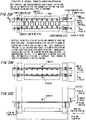
- two feed bars 10A and 10B extending in the workpiece conveying direction and being arranged opposed to each other approach to, from both sides, workpieces (material) being molded in respective stages (a first stage to a sixth stage are illustrated in FIG. 22 ) for multiple steps to clamp the workpieces in the respective steps with fingers 20A to 25A and fingers 20B to 25B.
- the workpieces are lifted up, advanced (moved to downstream in the workpiece conveying direction), and lifted down.
- the workpieces are unclamped (the feed bars 10A and 10B are moved apart from each other to release the workpieces) and returned (to original upstream positions in the workpiece conveying direction). Those operations are repeated to convey and work the workpieces through the respective stages.
- a linear-motion mechanism such as a ball screw or a rack and pinion.
- the two feed bars require the plurality of fingers corresponding to the respective stages to hold the workpieces in the respective stages. Consequently, weights of movable components are increased, and there is needed a driving unit capable of exerting a large driving force for simultaneously conveying the workpieces (materials) in all of the stages.
- a driving unit for lifting up and down, a driving unit (feed unit) for advancing and returning, and a driving unit for clamping and unclamping are driven by separate servomotors or the like (see FIG. 23A to FIG. 23C ).
- a driving unit for lifting up and down, a driving unit (feed unit) for advancing and returning, and a driving unit for clamping and unclamping are driven by separate servomotors or the like (see FIG. 23A to FIG. 23C ).
- high-power servomotors are required to move the feed bars (and finger units) having large lengths and large weights at high speed, and the movable components having large weights need to be supported.
- strength and rigidity of the apparatus also need to be increased. Consequently, in actuality, cost is increased.
- the feed bars and the finger units
- the feed bars have relatively large lengths and large inertia, and hence higher speed may cause resonance in the feed bars.
- critical speed is low, and the related-art feed bars are not suitable for high-speed conveyance (see FIG. 23B and FIG. 23C ).
- the movable components have large weights. Thus, in actuality, vibration noise is increased along with an increase in speed.
- Another configuration for conveying apparatuses is known from DE 101 28 189 A1 .
- several arms coupled to a crossbar configured to hold a workpiece are provided.
- Two of the arms are coupled to various moving units but to one common axle of the crossbar.
- the conveying apparatus has a third arm provided with a piston and coupled to one of the two moving units and another axle of the crossbar.
- the third arm is provided to tilt the crossbar about the common axle via a length variation thereof.
- the problem to be solved by the present invention is to provide a workpiece conveying apparatus having an alternative configuration and ideally overcoming the above indicated drawbacks of known systems.
- a workpiece conveying apparatus for a pressing machine including a conveying table including a workpiece supporting mechanism configured to support a workpiece in a releasable manner, a first arm and a second arm each having one end coupled to the conveying table so as to be pivotable through a pivot axis in a substantially vertical plane extending along a workpiece conveying direction, a first moving unit to which another end of the first arm is coupled so as to be pivotable through a pivot axis, a second moving unit to which another end of the second arm is coupled so as to be pivotable through a pivot axis and a posture control unit configured to control a posture of the conveying table through control of at least one of an angle between the conveying table and one of the first arm and the second arm, an angle between the first arm and the first moving unit, and an angle between the second arm and the second moving unit, in which the first moving unit and the second moving unit are movable by a moving mechanism in the workpiece conveying direction
- the pivot axis coupling the conveying table and the first arm to each other, and the pivot axis coupling the conveying table and the second arm to each other may be formed of separate pivot axes.
- the posture control unit comprises a first gear supported so as to be pivotable about the pivot axis coupling the conveying table and the first arm to each other and a second gear, which is meshed with the first gear, supported so as to be pivotable about the pivot axis coupling the conveying table and the second arm to each other. At least one of the combination of the first gear and the first arm, and the combination of the second gear and the second arm, is provided in a substantially integrated manner
- the first gear is substantially integrated with the first arm and the second gear is substantially integrated with the second arm.
- the pivot axis coupling the conveying table and the first arm to each other, and the pivot axis coupling the conveying table and the second arm to each other may be formed of a common pivot axis.
- the posture control unit may include a servomotor mounted substantially integrally with the conveying table, one of the first arm and the second arm may be pivotable about the common pivot axis by the servomotor with respect to the conveying table, and through control of drive of the servomotor, the angle between the conveying table and one of the first arm and the second arm may be controlled, thereby controlling the posture of the conveying table.
- a workpiece conveying apparatus in which, when the workpiece conveying apparatus includes a plurality of workpiece conveying apparatus arranged in the workpiece conveying direction, the plurality of workpiece conveying apparatus are configured to prevent mutual interference, and to be movable along the workpiece conveying direction while passing each other.
- the moving mechanism may include a linear motor.
- the present invention has been made in view of the above-mentioned circumstances, and has an object to provide a workpiece conveying apparatus, with a lightweight and compact configuration achieved relatively easily at low cost, capable of increasing a degree of freedom in posture of a workpiece during workpiece conveyance while reducing vibration noise, and capable of contributing to an increase in conveying speed of the workpiece, to a reduction in cycle time period, and to an increase in production efficiency.
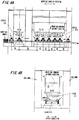
- a workpiece conveying apparatus 1 includes a pair of linear motor tables (moving units: movable members) 100 and 200 to be used to feed a workpiece (used to move, for example, advance and return the workpiece along a workpiece conveying direction).
- the linear motor tables (moving units: movable members) 100 and 200 are movable in the workpiece conveying direction above a linear motor unit 10 (stationary member: LM guide rail 11) extending in the workpiece conveying direction.
- the linear motor table 100 supports one end (lower end) of a corresponding arm 110 so as to be pivotable (rotatable or rockable) through a lower pivot shaft (or axis) 110B
- the linear motor table 200 supports one end (lower end) of a corresponding arm 120 so as to be pivotable (rotatable or rockable) through a lower pivot shaft (or axis) 120B.
- the conveying table 300 includes a workpiece supporting mechanism capable of supporting the workpiece in a releasable manner (such as a mechanism including a suction cup or the like arranged at a distal end of a clamping actuator 310 capable of expanding and contracting).
- the arm 110 corresponds to a first arm according to the present invention
- the arm 120 corresponds to a second arm according to the present invention
- the linear motor table 100 corresponds to a first moving unit according to the present invention
- the linear motor table 200 corresponds to a second moving unit according to the present invention.
- FIGS. 11 are illustrations of a configuration example of a linear servomotor including the linear motor tables (movable members) 100 and 200, the linear motor unit (magnet plate) 10 (stationary member: LM guide rail 11), and the like.
- the linear servomotor corresponds to an example of a moving mechanism according to the present invention.
- the linear motor tables (movable members) 100 and 200 can be driven and controlled independently of each other, and are configured so as to be movable independently of each other along a longitudinal direction of the linear motor unit 10 (LM guide rail 11).
- the linear motor table (movable member) 100 (200) is formed substantially integrally with an LM guide 101.
- the LM guide 101 is engaged with the LM guide rail 11 stationarily and substantially horizontally placed on an apparatus frame side (or floor side), to thereby be linearly guided while being restrained in transverse movement.
- the engagement between the LM guide 101 and the LM guide rail 11 prevents the linear motor table from falling in a lateral direction (width direction substantially orthogonal to the workpiece conveying direction) of the drawing sheet of FIG. 1B even under a reaction force or the like applied when the clamping actuator 310 holds the workpiece.
- the workpiece conveying apparatus 1 each including the linear motor tables (movable members) 100 and 200 and the linear motor unit (stationary member) 10 are arranged on both sides in the width direction with respect to the workpiece conveying direction across the workpiece or a die (lower die).
- the pair of opposed workpiece conveying apparatus 1 is configured to cooperate with each other to support and convey the workpiece.
- only one of the workpiece conveying apparatus 1 may be used.
- the two linear motor tables 100 and 200 are moved above the linear motor unit 10, that is, for example, the linear motor tables 100 and 200 are moved to approach to each other to enable the conveying table 300 and the workpiece to be lifted up, and the linear motor tables 100 and 200 are moved away from each other to enable the conveying table 300 and the workpiece to be lifted down.
- the linear motor tables 100 and 200 are moved away from each other to enable the conveying table 300 and the workpiece to be lifted down.
- the lower end sides of the arms 110 and 120 are respectively pivoted about (pin-coupled to) the linear motor tables 100 and 200 through the lower pivot shafts (or axes) 110B and 120B so as to be rotatable.
- the upper end sides of the arms 110 and 120 are pivoted about (pin-coupled to) the conveying table 300 through the upper pivot shafts (or axes) 110A and 120A so as to be rotatable.
- gears 111 and 121 are fixed substantially integrally with the upper end sides of the arms 110 and 120, respectively, and mesh with each other.
- the gears 111 and 121 have the same number of teeth and the same module, and are arranged so as to be rotatable about and coaxial with the upper pivot shafts (or axes) 110A and 120A, respectively.
- an angle between the conveying table 300 and the first arm 110 (or the second arm 120) is controlled through the meshing between the gears 111 and 121, thereby controlling the posture of the conveying table.
- the gear 111 corresponds to an example of a first gear according to the present invention
- the gear 121 corresponds to an example of a second gear according to the present invention.
- gears 111 and 121 which are fixed to the upper end sides of the arms 110 and 120 and mesh with each other, correspond to an example of a posture control unit according to the present invention.
- the present invention is not limited to the case of keeping the conveying table 300 substantially horizontal.
- the first gear and the second gear are not limited to gears having the same number of teeth and the same module.
- any unit capable of controlling the posture of the conveying table through control of the angle between the conveying table 300 and the arm 110 (first arm) or the arm 120 (second arm) may be employed as the posture control unit according to the present invention.
- the workpiece conveying apparatus 1 each including the linear motor tables 100 and 200, the arms 110 and 120, and the conveying table 300 are arranged on both sides across the workpiece or the die.
- the clamping actuator 310 or the like is mounted to each conveying table 300, thereby being capable of clamping and unclamping the workpiece. Therefore, unlike the related art, there can be omitted a driving unit having a large volume necessary to move all of the feed bars in order to clamp and unclamp the workpiece.
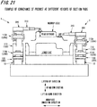
- the workpiece can be conveyed between the front and rear conveying tables 300 while clamping heights are varied.
- the workpiece can be conveyed at different clamping heights as appropriate in accordance with a workpiece shape or the like (see FIG. 21 ).
- both of the two linear motor tables 100 and 200 are moved in approaching directions to be brought close to each other, thereby being capable of shifting the conveying table 300 from the low position to the high position.
- the two linear motor tables 100 and 200 are moved in the same direction at different speed to be brought close to each other, thereby being capable of shifting the conveying table 300 from the low position to the high position. (The same holds true when the conveying table 300 is shifted from the high position to the low position.)
- a height of the conveying table 300 can be changed as appropriate through a change of a relative distance (interval) between the two linear motor tables 100 and 200 in the workpiece conveying direction (see FIG. 1A and the like).
- the workpiece is conveyed in the following manner.
- each workpiece conveying apparatus 1 conveys the workpiece from an upstream step (preceding step) to a downstream step (subsequent step) in a similar manner.
- Step 1 first, under a state in which the workpiece is supported (see FIG. 1C ), a pair of the workpiece conveying apparatus 1 each including the two linear motor tables 100 and 200 and being opposed to each other in the width direction (see FIG. 1C and FIG. 1B ) is moved above the linear motor unit 10 from a current position (for example, the left position X in FIG. 1B ) to a subsequent target position (for example, the right position Y in FIG. 1B ).
- a current position for example, the left position X in FIG. 1B
- a subsequent target position for example, the right position Y in FIG. 1B
- Step 2 the interval between the linear motor tables 100 and 200 in the workpiece conveying direction is increased at the position Y.
- the conveying table 300 and the workpiece are lifted down (lowered), and the workpiece is set on the lower die.
- the suction cups are taken away, thereby cancelling support of the workpiece.
- the clamping actuators 310 and the like are brought into a retracted state (state illustrated on the left side of FIG. 1B ).
- Step 3 under this state, a slide (upper die) is lowered to perform press working.
- Step 4 during the press working, each workpiece conveying apparatus 1 is returned to an original position (the left position X in FIG. 1B ). At this time, the interval between the linear motor tables 100 and 200 in the workpiece conveying direction is narrowed, and the conveying table 300 is lifted up to and kept at a predetermined height.
- Step 5 after the press working is finished so that there is no fear of interference with the slide, while the clamping actuators 310 and the like are extended again to be brought into a state illustrated on the right side of FIG. 1B , the interval between the linear motor tables 100 and 200 in the workpiece conveying direction is increased to lower the conveying table 300, and the suction cups suck the workpiece to support the workpiece.
- Step 6 after the workpiece is sucked in Step 5, the interval between the linear motor tables 100 and 200 in the workpiece conveying direction is narrowed, and the conveying table 300 and the workpiece are lifted up to the predetermined height (about a height at which the workpiece and the lower die do not interfere with each other) (see the state illustrated in FIG. 1C ).
- Steps 1 to 6 are repeated, thereby conveying the workpiece from the preceding step to the subsequent step.
- the workpiece previously located at the position Y is conveyed to a subsequent target position Z by another workpiece conveying apparatus 1 in the same manner described above.
- Press working is performed on the workpiece while the workpiece conveying apparatus 1 according to the first embodiment continuously conveys, through repetition of Steps described above, the workpiece onto dies aligned on one slide in the stage order.
- workpiece conveying apparatus 1 is not limited to the case where the workpiece conveying apparatus is used as the above-mentioned transfer apparatus.
- the workpiece conveying apparatus may be used for conveyance of the workpiece between presses.
- the workpiece can be conveyed with a relatively lightweight and compact configuration including the linear motor tables 100 and 200, the arms 110 and 120, and the conveying table 300. Accordingly, the related-art feed bars having large sizes and large weights can be omitted, thereby being capable of omitting a large-volume actuator configured to move the feed bars and the like. Therefore, the lightweight and compact configuration can be achieved relatively easily at low cost.
- the lightweight and compact configuration can increase a degree of freedom in posture of the workpiece during workpiece conveyance while reducing vibration noise, and can contribute to an increase in conveying speed of the workpiece, a reduction in cycle time period, an increase in production efficiency, and the like.
- the number of arms may be increased, and, as illustrated in FIG. 2 , arms 1101 and 1201 may be arranged in a cross shape (pantograph shape). Such a configuration may involve a large lifting amount to cope with the above-mentioned case.
- the respective conveying tables 300 can be concentrated at a center portion or the like within a compact region. Accordingly, unnecessary movement and the like can be reduced during changeover work (or set-up) and the like. Consequently, the changeover work (or set-up) can be performed efficiently.
- the related-art transfer apparatus simultaneously clamps workpieces (materials) in all steps by the feed bars and the fingers, and then conveys each of the workpieces from upstream to downstream. Accordingly, a feeding distance of the feed bars corresponds to a feeding pitch of all of the materials (interval between respective stages (respective dies)).
- step pitches can be designed with reference to, for example, strength of dies, thereby being capable of achieving a design and the like enabling a reduction in die cost.
- fingers configured to hold the workpiece may be mounted to the distal end of the clamping actuator 310.
- the pair of feed bars arranged in an opposed manner simultaneously clamps the workpieces (materials) in all steps, and then conveys each of the workpieces from the upstream to the downstream in the conveying direction (see FIG. 22 , FIG. 23A , and the like). Accordingly, from the upstream to the downstream in the conveying direction, products are sequentially formed with dies aligned in the step order.
- the feed bars and the fingers simultaneously clamp the workpieces (materials) in all steps, and then convey the workpieces from the upstream to the downstream. Accordingly, the related-art transfer apparatus can perform only sequential feed forming (forming in which forming steps proceed from upstream to downstream).
- workpiece conveying apparatus 1 and 2 are arranged side by side in the width direction (direction substantially orthogonal to the workpiece conveying direction), and lifting heights are set so that the fingers, the actuators, and the like configured to clamp the workpiece cause no interference with the workpiece.
- the workpiece conveying apparatus 1 and the workpiece conveying apparatus 2 are movable in the workpiece conveying direction while passing each other. With this, the workpiece can be conveyed to an arbitrary step without being sequentially conveyed from the upstream to the downstream.
- workpiece conveying apparatus 1, 2, and 3 may be arranged in three lines in the width direction, and the step order (appropriate step order) illustrated in FIG. 7A may be adopted.
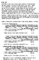
- FIGS. 16 there are shown calculation results of a comparison between an eccentric load ratio of first to fifth steps in related-art transfer working (processing method in which working steps sequentially proceed from the upstream to the downstream), and an eccentric load ratio of first to fifth steps in transfer working according to this embodiment (processing method in which the order of working steps is interchanged to reduce an eccentric load) (see FIG. 17 for mathematical expressions and the like).
- the ratio of the eccentric load applied to the slide can be reduced to about a half of the eccentric load ratio of the related art when the order of working steps is interchanged. Accordingly, an increase in accuracy of a formed product and contribution to elongation of a die lifetime can be expected.
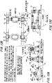
- any one of the gears 111 and 121 (for example, the gear 121 (equalizing gear b) on the arm 120 (arm b) side), which is pivotable about the upper pivot shaft (or axis) 110A or 120A and fixed to the arm 110 or 120, is configured to be rotatable relative to the arm 120 (arm b) about the upper pivot shaft (or axis) 120A (about a rotation center of the gear 121 (equalizing gear b)) by a servomotor 210, and to be capable of stopping or remaining at a predetermined rotation angle position.
- Any one of the gears 111 and 121 is rotated by the preset rotation angle, thereby being capable of inclining (leaning or tilting) the workpiece (material) as illustrated in FIG. 8A and FIG. 9 .
- the workpiece when the workpiece is lifted down, the workpiece is not lowered vertically, but can be lowered in an arbitrary manner in each step, for example, obliquely in accordance with an orientation of the die. Accordingly, in a piercing step or the like, the workpiece (material) can be lowered to be brought into a state of being inclined at an arbitrary angle ( FIG. 8B and FIG. 8C ), and then set on the die (lower die). Thus, there can be avoided such a situation in which an arrival angle of a punch is oblique to a surface of the workpiece (see FIG. 10A ) when the workpiece (material) is lowered with horizontal balance as in the related art.
- the punch can be vertically pressed into the surface of the workpiece (see FIG. 10B ). Accordingly, the above-mentioned configuration can contribute to an increase in processing accuracy and an appearance of a cross-section of a formed hole, and can achieve production capable of increasing a punch lifetime because bending moment is not applied to the punch.
- a mechanism enabling the conveying table 300 to be rotated by the servomotor 210 relative to the arm 120 (arm b) and enabling the conveying table 300 to stop or remain at the predetermined rotation angle position so as to incline (lean or tilt) the workpiece (material) corresponds to an example of the posture control unit according to the present invention.
- an angle between the conveying table 300 and the second arm 120 (or the first arm 110) is controlled through rotation control of the servomotor 210, thereby controlling the posture of the conveying table.
- the upper pivot shafts (or axes) 110A and 120A of the two arms 110 and 120 which are supported on the two linear motor tables 100 and 200 so as to be rotatable about the lower pivot shafts (or axes) 110B and 120B, are arranged substantially in parallel to the flat surface 300A of the conveying table 300. Further, the conveying table 300 is used as one link.
- the upper pivot shafts (or axes) of the two arms 110 and 120 are modified into a single common pivot shaft (or axis) 400B, and the pivot shaft (or axis) 400B supports a conveying table 400.
- a servomotor 410 is stationarily fixed to the conveying table 400, and an output shaft (or axis) of the servomotor 410 and the arm 120 (arm b) are coupled substantially integrally with each other. Further, the servomotor 410 can rotate the arm 120 (arm b) relative to the conveying table 400 about the pivot shaft (or axis) 400B, and the arm 120 can stop or remain at the predetermined rotation angle position.
- a pivot shaft (or axis) height h of the conveying table 400 is determined by relative positions (interval) of the two linear motor tables 100 and 200 driven independently of each other.
- the servomotor 410 always performs control so as to keep a flat surface 400A of the conveying table 400 substantially horizontal or forming a predetermined tilt angle ⁇ .
- a mechanism enabling the conveying table 300 to be rotated by the servomotor 410 relative to the arm 120 (arm b) and enabling the conveying table 300 to stop or remain at the predetermined rotation angle position so as to incline (lean or tilt) the workpiece (material) corresponds to an example of the posture control unit according to the present invention.
- an angle between the conveying table 300 and the second arm 120 (or the first arm 110) is controlled through rotation control of the servomotor 410, thereby controlling the posture of the conveying table.
- a mode in which the servomotor 410 is stationarily fixed to the conveying table 400 there is exemplified a mode in which the servomotor 410 is stationarily fixed to the conveying table 400.
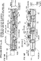
- a servomotor 510 in place of the servomotor 410, is mounted to the linear motor table 200 (or 100), and an output rotation shaft of the servomotor 510 and the arm 120 (arm b) are coupled to each other in a rotatable manner. Further, the servomotor 510 is rotatable about the lower pivot shaft (or axis) 120B independently of the arm 120 (arm b).
- the pivot shaft (or axis) height h of the conveying table 400 is determined by the relative positions (interval) of the two linear motor tables 100 and 200 driven independently of each other.
- a position of the conveying table 400 about the pivot shaft (or axis) 400B (angular position of the flat surface 400A about the pivot shaft (or axis) 400B) is not fixed.
- a pulley 511 substantially integrated with the conveying table 400 so as to be rotatable about the pivot shaft (or axis) 400B, and a pulley 512 rotating substantially integrally with the output shaft of the servomotor 510.
- a belt 513 is stretched around the pulley 511 and the pulley 512.
- the pulley 511 is rotated through the pulley 512 and the belt 513 by the predetermined rotation angle.
- the conveying table 400 substantially integrated with the pulley 511 is rotated about the pivot shaft (or axis) 400B.
- the servomotor 510 can always perform control so as to keep the flat surface 400A of the conveying table 400 substantially horizontal or forming a predetermined tilt angle ⁇ .
- the servomotor 510 is rotatable, and is capable of stopping or remaining at the predetermined rotation angle position.
- a mechanism of always performing control using the servomotor 510, the pulley 511, the pulley 512, and the belt 513 so as to keep the flat surface 400A of the conveying table 400 substantially horizontal or forming the predetermined tilt angle ⁇ corresponds to an example of the posture control unit according to the present invention.
- an angle between the conveying table 300 and the second arm 120 (or the first arm 110) is controlled through rotation control of the servomotor 510, thereby controlling the posture of the conveying table.
- the conveying table 300 (400) is supported by the two arms 110 and 120 that are supported on the two linear motor tables 100 and 200 so as to be rotatable about the lower pivot shafts (or axes) 110B and 120B.
- a sixth embodiment of the present invention as illustrated in FIG. 14A and FIG. 14B , in place of the two linear motor tables 100 and 200, two tables 1000 and 2000 can be moved by ball screws 600 driven by servomotors 610 and 611.
- the table 1000 corresponds to the first moving unit according to the present invention
- the table 2000 corresponds to the second moving unit according to the present invention.
- the two tables 1000 and 2000 on which the two arms 110 and 120 are supported so as to be rotatable about the lower pivot shafts (or axes) 110B and 120B, are linearly moved and guided along linear guide rails (LM guide rails), the two tables 1000 and 2000 can be moved in a longitudinal direction of shafts 620 and 621 by the ball screws 600 engaged with threaded outer peripheries of the shafts 620 and 621.
- LM guide rails linear guide rails
- the mechanism of moving the two tables, on which the two arms 110 and 120 are supported so as to be rotatable is not limited to a mechanism of driving the two tables by linear motors.
- a case of moving the two tables using a ball screw mechanism as described in the sixth embodiment (corresponding to an example of the moving mechanism according to the present invention), and a case of moving the two tables using a gear mechanism, belt driving, or the like may be also adopted.
- a degree of freedom in movement of the two tables is determined based on the number of drive sources and complexity of a mechanism.
- the same operations and effects as those of the above-mentioned first embodiment can be obtained. That is, the related-art feed bars having large sizes and large weights can be omitted, thereby being capable of omitting a large-volume actuator configured to move the feed bars and the like. Therefore, the lightweight and compact configuration can be achieved relatively easily at low cost.
- the lightweight and compact configuration can increase a degree of freedom in the posture of the workpiece during workpiece conveyance while reducing vibration noise, and can contribute to an increase in conveying speed of the workpiece, a reduction in cycle time period, an increase in production efficiency, and the like.
- the linear motor tables 100 and 200 can stop or remain at predetermined positions so as to be capable of overcoming loads through drive control. As illustrated in FIG. 18 , when linear thrust forces F1 are generated, a lifting force F2 is obtained.
- a lying-down preventing roller 112 configured to restrain downward movement of the arms 110 and 120 immediately before the arms 110 and 120 are brought into a horizontal state.
- the arms 110 and 120 can be reliably prevented from being brought into a horizontal state to be uncontrollable.
- the gears 111 and 121 according to the first embodiment are omitted, and springs 113 and 123 are adopted.
- the spring 113 is arranged so as to allow the arm 110 to be rotated about the upper pivot shaft (or axis) 110A, and so as to elastically urge the arm 110 in a direction of bringing the arm 110 into a substantially upright state (direction of moving the arm 110 so that the angle ⁇ of the arm 110 about the lower pivot shaft (or axis) 110B forms 90 degrees).
- one end of the spring (power spring) 123 is fixed to the arm 120, and another end thereof is fixed to the conveying table 300.
- the spring 123 is arranged so as to allow the arm 120 to be rotated about the upper pivot shaft (or axis) 120A, and so as to elastically urge the arm 120 in a direction of bringing the arm 120 into a substantially upright state (direction of moving the arm 120 so that the angle ⁇ of the arm 120 about the lower pivot shaft (or axis) 120B forms 90 degrees).
- the springs 113 and 123 correspond to an example of the posture control unit according to the present invention.
- the angle between the conveying table 300 and the second arm 120 (or the first arm 110) is controlled by the springs 113 and 123, thereby controlling the posture of the conveying table.
- a lifting force of lifting up the conveying table 300 is a resultant force of the lifting force F2 generated when the linear motor tables 100 and 200 generate the linear thrust forces F1, and of a lifting force F3 resulting from elastic forces of the springs 113 and 123.
- the springs 113 and 123 are adopted, even in a case where power is rotated off to cause the linear thrust forces of the linear motor tables 100 and 200 to be lost, the springs 113 and 123 are returned to original states ( FIG. 20A ) owing to restoring forces thereof. Thus, the arms 110 and 120 can be reliably prevented from being horizontal and uncontrollable.
- the springs 113 and 123 may be used in combination with equalizing gears (gears 111 and 121).
- one of the gears 111 and 121 may be configured to be rotatable relative to the arm 120 about the upper pivot shaft (or axis) 120A (about the rotation center of the gear 121) by the servomotor, and to be capable of stopping or remaining at the predetermined rotation angle position.
- Any one of the gears 111 and 121 may be configured to be capable of, by being rotated by the preset rotation angle, inclining (leaning) the workpiece (material) at an arbitrary angle as illustrated in FIG. 8A and FIG. 9 .
- the interval between the tables 100 and 200 of one workpiece conveying apparatus 1, and the interval between the tables 100 and 200 of another workpiece conveying apparatus 1 can be easily varied from each other through drive control of linear motors (or the servomotors and the ball screw mechanisms according to the sixth embodiment).
- the one workpiece conveying apparatus 1 and the another workpiece conveying apparatus 1 are arranged across the lower die in a direction substantially orthogonal to the workpiece conveying direction. Accordingly, using this, for example, heights of the conveying tables 300 are varied between the two workpiece conveying apparatus 1 arranged across the same lower die in an opposed manner.
- This configuration can easily cope with a case where heights of supporting the workpiece are not laterally symmetrical in the width direction, for example, a case where the supporting heights are different from each other.
- positions of the two workpiece conveying apparatus 1 can be easily varied through drive control of linear motors (or the servomotors and the ball screw mechanism according to the sixth embodiment), thereby being capable of easily coping with the above-mentioned case.
- the angle between the conveying table and the second arm is controlled by the servomotor or the like, thereby controlling the posture of the conveying table.
- the posture of the conveying table can be also controlled through control, by the servomotor, of an angle between the first arm (arm 110) and the first moving unit (linear motor table 100), or an angle between the second arm (arm 120) and the second moving unit (linear motor table 200).
- the present invention also encompasses this configuration.
Landscapes
- Engineering & Computer Science (AREA)
- Mechanical Engineering (AREA)
- Press Drives And Press Lines (AREA)
- Manipulator (AREA)
Claims (5)
- Eine Werkstückfördervorrichtung (1) für eine Pressmaschine, umfassend:einen Fördertisch (300), der einen Werkstückhaltemechanismus umfasst, der so konfiguriert ist, dass er ein Werkstück in einer lösbaren Weise hält;einen ersten Arm (110) und einen zweiten Arm (120), die jeweils mit einem Ende an den Fördertisch (300) gekoppelt sind, so dass sie über eine Schwenkachse (110A, 120A) in einer im Wesentlichen vertikalen Ebene, die sich entlang einer Werkstück-Förderrichtung erstreckt, schwenkbar sind;eine erste Bewegungseinheit (100), an die ein anderes Ende des ersten Arms (110) so gekoppelt ist, dass es um eine Schwenkachse (110B) herum schwenkbar ist;eine zweite Bewegungseinheit (200), an die ein anderes Ende des zweiten Arms (210) so gekoppelt ist, dass es um eine Schwenkachse (120B) herum schwenkbar ist; undeine Stellungssteuereinheit, die so konfiguriert ist, dass sie eine Stellung des Fördertisches (300) durch die Steuerung eines Winkels zwischen dem Fördertisch (300) und dem ersten Arm (110) und/oder dem zweiten Arm (210), eines Winkels zwischen dem ersten Arm (110) und der ersten Bewegungseinheit (100) und/oder eines Winkels zwischen dem zweiten Arm (210) und der zweiten Bewegungseinheit (220) steuert,wobei die erste Bewegungseinheit (100) und die zweite Bewegungseinheit (200) durch einen Bewegungsmechanismus in der Werkstück-Förderrichtung beweglich sind,wobei der Fördertisch (300) durch eine Änderung eines Abstands zwischen der ersten Bewegungseinheit (100) und der zweiten Bewegungseinheit (200) angehoben und abgesenkt wird, undwobei die erste Bewegungseinheit (100) und die zweite Bewegungseinheit (200) in der gleichen Werkstück-Förderrichtung bewegt werden, um den Fördertisch (300) in der Werkstück-Förderrichtung zu bewegen, um dadurch das Werkstück zu fördern;wobei die Schwenkachse (110A), die den Fördertisch (300) und den ersten Arm (110) miteinander verbindet, und die Schwenkachse (120A), die den Fördertisch (300) und den zweiten Arm (120) miteinander verbindet, aus getrennten Schwenkachsen gebildet sind,dadurch gekennzeichnet, dassdie Stellungssteuereinheit umfasst:ein erstes Zahnrad (111), das um die Schwenkachse (110A), die den Fördertisch (300) und den ersten Arm (110) miteinander verbindet, herum schwenkbar gelagert ist; undein zweites Zahnrad (121), das mit dem ersten Zahnrad (111) im Eingriff steht und um die Schwenkachse (120A), die den Fördertisch (300) und den zweiten Arm (120) miteinander verbindet, herum schwenkbar gelagert ist,wobei die Kombination aus dem ersten Zahnrad (111) und dem ersten Arm (110) und/oder die Kombination aus dem zweiten Zahnrad (121) und dem zweiten Arm (120) im Wesentlichen integriert vorgesehen ist.
- Eine Werkstückfördervorrichtung (1) für eine Pressmaschine nach Anspruch 1, wobei die Schwenkachse (110A), die den Fördertisch (300) und den ersten Arm (110) miteinander verbindet, und die Schwenkachse (120A), die den Fördertisch (300) und den zweiten Arm (120) miteinander verbindet, aus einer gemeinsamen Schwenkachse (400B) gebildet sind.
- Eine Werkstückfördervorrichtung (1) für eine Pressmaschine nach Anspruch 2,
wobei die Stellungssteuereinheit einen Servomotor (410) umfasst, der im Wesentlichen integral mit dem Fördertisch (300) montiert ist,
wobei entweder der erste Arm (110) oder der zweite Arm (120) durch den Servomotor (410) um die gemeinsame Schwenkachse (400B) herum in Bezug auf den Fördertisch schwenkbar ist, und
wobei durch die Steuerung des Antriebs des Servomotors (410) der Winkel zwischen dem Fördertisch (300) und einem des ersten Arms (110) und des zweiten Arms (120) gesteuert wird, wodurch die Stellung des Fördertisches (300) gesteuert wird. - Eine Werkstückfördervorrichtung (1) für eine Pressmaschine nach einem der Ansprüche 1 bis 3, wobei, wenn die Werkstückfördervorrichtung (1) eine Vielzahl von Werkstückfördervorrichtungen (1) umfasst, die in der Werkstückförderrichtung angeordnet sind, die Vielzahl von Werkstückfördervorrichtungen (1) so konfiguriert ist, dass sie eine gegenseitige Behinderung verhindern und entlang der Werkstück-Förderrichtung beweglich sind, während sie aneinander vorbeilaufen.
- Eine Werkstückfördervorrichtung (1) für eine Pressmaschine nach einem der Ansprüche 1 bis 4, wobei der Bewegungsmechanismus einen Linearmotor umfasst.
Applications Claiming Priority (1)
| Application Number | Priority Date | Filing Date | Title |
|---|---|---|---|
| JP2015241068A JP6192131B2 (ja) | 2015-12-10 | 2015-12-10 | プレス機械のワーク搬送装置 |
Publications (2)
| Publication Number | Publication Date |
|---|---|
| EP3178582A1 EP3178582A1 (de) | 2017-06-14 |
| EP3178582B1 true EP3178582B1 (de) | 2020-05-13 |
Family
ID=57539108
Family Applications (1)
| Application Number | Title | Priority Date | Filing Date |
|---|---|---|---|
| EP16203036.5A Active EP3178582B1 (de) | 2015-12-10 | 2016-12-08 | Werkstückfördervorrichtung für eine pressmaschine |
Country Status (4)
| Country | Link |
|---|---|
| US (1) | US10532392B2 (de) |
| EP (1) | EP3178582B1 (de) |
| JP (1) | JP6192131B2 (de) |
| CN (1) | CN106863897B (de) |
Families Citing this family (7)
| Publication number | Priority date | Publication date | Assignee | Title |
|---|---|---|---|---|
| CN107309332B (zh) * | 2017-07-05 | 2023-03-07 | 东莞美和珠宝有限公司 | 一种全自动锤珠机 |
| JP2020116668A (ja) * | 2019-01-22 | 2020-08-06 | Ntn株式会社 | ワーク搬送装置 |
| JP7083322B2 (ja) * | 2019-07-17 | 2022-06-10 | アイダエンジニアリング株式会社 | トランスファープレスマシンのワーク搬送システム |
| JP7267190B2 (ja) * | 2019-12-26 | 2023-05-01 | アイダエンジニアリング株式会社 | トランスファ機構およびトランスファ装置 |
| CN113579073B (zh) * | 2021-08-05 | 2023-07-21 | 贵州盛昌铝业有限公司 | 一种铝型材冲压成型设备 |
| CN114543006B (zh) * | 2022-02-21 | 2023-11-07 | 佛山电器照明股份有限公司 | 一种led照明灯具组装生产线 |
| CN114772893B (zh) * | 2022-04-13 | 2023-09-29 | 湖南大自然环保股份有限公司 | 一种市政污泥干化处理装置及方法 |
Family Cites Families (18)
| Publication number | Priority date | Publication date | Assignee | Title |
|---|---|---|---|---|
| US1681012A (en) * | 1926-09-02 | 1928-08-14 | Marquette Tool & Mfg Co | Sheet-metal press |
| JPS5549859Y2 (de) * | 1976-12-09 | 1980-11-20 | ||
| DE19721613A1 (de) * | 1997-05-23 | 1998-11-26 | Schuler Pressen Gmbh & Co | Presse mit einer Umsetzeinrichtung für Werkstücke |
| DE19740293A1 (de) * | 1997-09-13 | 1999-03-18 | Schuler Pressen Gmbh & Co | Transferpressen mit automatischem Toolingwechsel |
| JPH11292479A (ja) * | 1998-04-10 | 1999-10-26 | Murata Mach Ltd | 板材ローダ |
| DE10128189B4 (de) * | 2001-06-11 | 2004-08-05 | Fraunhofer-Gesellschaft zur Förderung der angewandten Forschung e.V. | Transport- und/oder Lagerungsvorrichtung für Werkstücke |
| JP4778698B2 (ja) * | 2003-10-23 | 2011-09-21 | 株式会社小松製作所 | プレス機械のワーク搬送装置 |
| CN100429017C (zh) * | 2003-10-23 | 2008-10-29 | 株式会社小松制作所 | 压力机械的工件搬送装置 |
| DE10352982B4 (de) * | 2003-11-13 | 2007-06-21 | Müller Weingarten AG | Gelenkarmtransportvorrichtung |
| ATE443584T1 (de) * | 2006-01-24 | 2009-10-15 | Hatebur Umformmaschinen Ag | Werkstücktransportvorrichtung |
| DE102006038505A1 (de) * | 2006-08-16 | 2008-02-21 | Kmb Produktions Ag | Vorrichtung zum Versetzen von Gegenständen |
| JP4363432B2 (ja) * | 2006-09-21 | 2009-11-11 | 村田機械株式会社 | 移載装置 |
| TWI398335B (zh) * | 2006-11-27 | 2013-06-11 | Nidec Sankyo Corp | Workpiece conveying system |
| JP5330182B2 (ja) * | 2009-10-05 | 2013-10-30 | アイダエンジニアリング株式会社 | ワーク搬送装置 |
| CN201647654U (zh) * | 2010-03-22 | 2010-11-24 | 宁波奇亿金属有限公司 | 引带输送装置 |
| JP5793109B2 (ja) * | 2012-05-15 | 2015-10-14 | アイダエンジニアリング株式会社 | ワーク搬送装置 |
| CN102658947A (zh) * | 2012-06-04 | 2012-09-12 | 天润曲轴股份有限公司 | 一种步进式轴类工件输送装置 |
| JP2015196235A (ja) * | 2014-04-03 | 2015-11-09 | ファナック株式会社 | ワーク搬送システム |
-
2015
- 2015-12-10 JP JP2015241068A patent/JP6192131B2/ja active Active
-
2016
- 2016-11-22 CN CN201611031225.9A patent/CN106863897B/zh active Active
- 2016-12-08 US US15/373,272 patent/US10532392B2/en active Active
- 2016-12-08 EP EP16203036.5A patent/EP3178582B1/de active Active
Non-Patent Citations (1)
| Title |
|---|
| None * |
Also Published As
| Publication number | Publication date |
|---|---|
| US10532392B2 (en) | 2020-01-14 |
| EP3178582A1 (de) | 2017-06-14 |
| CN106863897A (zh) | 2017-06-20 |
| JP2017104886A (ja) | 2017-06-15 |
| US20170165738A1 (en) | 2017-06-15 |
| JP6192131B2 (ja) | 2017-09-06 |
| CN106863897B (zh) | 2019-03-29 |
Similar Documents
| Publication | Publication Date | Title |
|---|---|---|
| EP3178582B1 (de) | Werkstückfördervorrichtung für eine pressmaschine | |
| US10052678B2 (en) | Workpiece conveying apparatus for a pressing machine | |
| US10300520B2 (en) | Workpiece conveying apparatus for a pressing machine with two robots | |
| JP5884787B2 (ja) | 移載装置、及び移載方法 | |
| CN101829737A (zh) | 一种送料装置及利用其送料方法 | |
| JP3902006B2 (ja) | タンデムプレスラインのワーク搬送方法及びワーク搬送装置 | |
| JP3090789B2 (ja) | トランスファプレス | |
| CN106311818A (zh) | 弯折装置 | |
| JPS61103625A (ja) | パネルフオ−マ− | |
| KR101771048B1 (ko) | 전조기 및 전조 가공 방법 | |
| KR101292194B1 (ko) | 승강 장치 | |
| KR20170081905A (ko) | 복합프레스장치 | |
| JP2004074209A (ja) | 複数台プレストランスファ装置 | |
| KR100195830B1 (ko) | 트랜스퍼 피더 | |
| JPH07148710A (ja) | 両端ほぞ加工装置 | |
| JP4781881B2 (ja) | トランスファプレスのフィードバー駆動装置 | |
| KR20170125821A (ko) | 공작물을 점진적으로 전진시키기 위한 장치 | |
| JP4715266B2 (ja) | パネル搬送装置 | |
| JP5275663B2 (ja) | 異形断面バー材の供給装置及び加工装置 | |
| JPH1190561A (ja) | トランスファフィーダ | |
| JP2009056477A (ja) | プレス設備のワーク自動搬送装置 | |
| CN214827165U (zh) | 板材规整推送机 | |
| JP2003290850A (ja) | プレス機械のワーク搬送装置 | |
| JP6321088B2 (ja) | タンデムプレスライン搬送方法 | |
| JP2004268074A (ja) | トランスファプレスのワーク搬送装置 |
Legal Events
| Date | Code | Title | Description |
|---|---|---|---|
| PUAI | Public reference made under article 153(3) epc to a published international application that has entered the european phase |
Free format text: ORIGINAL CODE: 0009012 |
|
| STAA | Information on the status of an ep patent application or granted ep patent |
Free format text: STATUS: THE APPLICATION HAS BEEN PUBLISHED |
|
| AK | Designated contracting states |
Kind code of ref document: A1 Designated state(s): AL AT BE BG CH CY CZ DE DK EE ES FI FR GB GR HR HU IE IS IT LI LT LU LV MC MK MT NL NO PL PT RO RS SE SI SK SM TR |
|
| AX | Request for extension of the european patent |
Extension state: BA ME |
|
| STAA | Information on the status of an ep patent application or granted ep patent |
Free format text: STATUS: REQUEST FOR EXAMINATION WAS MADE |
|
| 17P | Request for examination filed |
Effective date: 20171207 |
|
| RBV | Designated contracting states (corrected) |
Designated state(s): AL AT BE BG CH CY CZ DE DK EE ES FI FR GB GR HR HU IE IS IT LI LT LU LV MC MK MT NL NO PL PT RO RS SE SI SK SM TR |
|
| GRAP | Despatch of communication of intention to grant a patent |
Free format text: ORIGINAL CODE: EPIDOSNIGR1 |
|
| STAA | Information on the status of an ep patent application or granted ep patent |
Free format text: STATUS: GRANT OF PATENT IS INTENDED |
|
| INTG | Intention to grant announced |
Effective date: 20191206 |
|
| GRAS | Grant fee paid |
Free format text: ORIGINAL CODE: EPIDOSNIGR3 |
|
| GRAA | (expected) grant |
Free format text: ORIGINAL CODE: 0009210 |
|
| STAA | Information on the status of an ep patent application or granted ep patent |
Free format text: STATUS: THE PATENT HAS BEEN GRANTED |
|
| AK | Designated contracting states |
Kind code of ref document: B1 Designated state(s): AL AT BE BG CH CY CZ DE DK EE ES FI FR GB GR HR HU IE IS IT LI LT LU LV MC MK MT NL NO PL PT RO RS SE SI SK SM TR |
|
| REG | Reference to a national code |
Ref country code: GB Ref legal event code: FG4D |
|
| REG | Reference to a national code |
Ref country code: CH Ref legal event code: EP |
|
| REG | Reference to a national code |
Ref country code: DE Ref legal event code: R096 Ref document number: 602016036299 Country of ref document: DE |
|
| REG | Reference to a national code |
Ref country code: AT Ref legal event code: REF Ref document number: 1269582 Country of ref document: AT Kind code of ref document: T Effective date: 20200615 |
|
| REG | Reference to a national code |
Ref country code: LT Ref legal event code: MG4D |
|
| REG | Reference to a national code |
Ref country code: NL Ref legal event code: MP Effective date: 20200513 |
|
| PG25 | Lapsed in a contracting state [announced via postgrant information from national office to epo] |
Ref country code: PT Free format text: LAPSE BECAUSE OF FAILURE TO SUBMIT A TRANSLATION OF THE DESCRIPTION OR TO PAY THE FEE WITHIN THE PRESCRIBED TIME-LIMIT Effective date: 20200914 Ref country code: LT Free format text: LAPSE BECAUSE OF FAILURE TO SUBMIT A TRANSLATION OF THE DESCRIPTION OR TO PAY THE FEE WITHIN THE PRESCRIBED TIME-LIMIT Effective date: 20200513 Ref country code: FI Free format text: LAPSE BECAUSE OF FAILURE TO SUBMIT A TRANSLATION OF THE DESCRIPTION OR TO PAY THE FEE WITHIN THE PRESCRIBED TIME-LIMIT Effective date: 20200513 Ref country code: GR Free format text: LAPSE BECAUSE OF FAILURE TO SUBMIT A TRANSLATION OF THE DESCRIPTION OR TO PAY THE FEE WITHIN THE PRESCRIBED TIME-LIMIT Effective date: 20200814 Ref country code: NO Free format text: LAPSE BECAUSE OF FAILURE TO SUBMIT A TRANSLATION OF THE DESCRIPTION OR TO PAY THE FEE WITHIN THE PRESCRIBED TIME-LIMIT Effective date: 20200813 Ref country code: IS Free format text: LAPSE BECAUSE OF FAILURE TO SUBMIT A TRANSLATION OF THE DESCRIPTION OR TO PAY THE FEE WITHIN THE PRESCRIBED TIME-LIMIT Effective date: 20200913 Ref country code: SE Free format text: LAPSE BECAUSE OF FAILURE TO SUBMIT A TRANSLATION OF THE DESCRIPTION OR TO PAY THE FEE WITHIN THE PRESCRIBED TIME-LIMIT Effective date: 20200513 |
|
| PG25 | Lapsed in a contracting state [announced via postgrant information from national office to epo] |
Ref country code: BG Free format text: LAPSE BECAUSE OF FAILURE TO SUBMIT A TRANSLATION OF THE DESCRIPTION OR TO PAY THE FEE WITHIN THE PRESCRIBED TIME-LIMIT Effective date: 20200813 Ref country code: HR Free format text: LAPSE BECAUSE OF FAILURE TO SUBMIT A TRANSLATION OF THE DESCRIPTION OR TO PAY THE FEE WITHIN THE PRESCRIBED TIME-LIMIT Effective date: 20200513 Ref country code: RS Free format text: LAPSE BECAUSE OF FAILURE TO SUBMIT A TRANSLATION OF THE DESCRIPTION OR TO PAY THE FEE WITHIN THE PRESCRIBED TIME-LIMIT Effective date: 20200513 Ref country code: LV Free format text: LAPSE BECAUSE OF FAILURE TO SUBMIT A TRANSLATION OF THE DESCRIPTION OR TO PAY THE FEE WITHIN THE PRESCRIBED TIME-LIMIT Effective date: 20200513 |
|
| REG | Reference to a national code |
Ref country code: AT Ref legal event code: MK05 Ref document number: 1269582 Country of ref document: AT Kind code of ref document: T Effective date: 20200513 |
|
| PG25 | Lapsed in a contracting state [announced via postgrant information from national office to epo] |
Ref country code: NL Free format text: LAPSE BECAUSE OF FAILURE TO SUBMIT A TRANSLATION OF THE DESCRIPTION OR TO PAY THE FEE WITHIN THE PRESCRIBED TIME-LIMIT Effective date: 20200513 Ref country code: AL Free format text: LAPSE BECAUSE OF FAILURE TO SUBMIT A TRANSLATION OF THE DESCRIPTION OR TO PAY THE FEE WITHIN THE PRESCRIBED TIME-LIMIT Effective date: 20200513 |
|
| PG25 | Lapsed in a contracting state [announced via postgrant information from national office to epo] |
Ref country code: AT Free format text: LAPSE BECAUSE OF FAILURE TO SUBMIT A TRANSLATION OF THE DESCRIPTION OR TO PAY THE FEE WITHIN THE PRESCRIBED TIME-LIMIT Effective date: 20200513 Ref country code: CZ Free format text: LAPSE BECAUSE OF FAILURE TO SUBMIT A TRANSLATION OF THE DESCRIPTION OR TO PAY THE FEE WITHIN THE PRESCRIBED TIME-LIMIT Effective date: 20200513 Ref country code: RO Free format text: LAPSE BECAUSE OF FAILURE TO SUBMIT A TRANSLATION OF THE DESCRIPTION OR TO PAY THE FEE WITHIN THE PRESCRIBED TIME-LIMIT Effective date: 20200513 Ref country code: IT Free format text: LAPSE BECAUSE OF FAILURE TO SUBMIT A TRANSLATION OF THE DESCRIPTION OR TO PAY THE FEE WITHIN THE PRESCRIBED TIME-LIMIT Effective date: 20200513 Ref country code: ES Free format text: LAPSE BECAUSE OF FAILURE TO SUBMIT A TRANSLATION OF THE DESCRIPTION OR TO PAY THE FEE WITHIN THE PRESCRIBED TIME-LIMIT Effective date: 20200513 Ref country code: DK Free format text: LAPSE BECAUSE OF FAILURE TO SUBMIT A TRANSLATION OF THE DESCRIPTION OR TO PAY THE FEE WITHIN THE PRESCRIBED TIME-LIMIT Effective date: 20200513 Ref country code: EE Free format text: LAPSE BECAUSE OF FAILURE TO SUBMIT A TRANSLATION OF THE DESCRIPTION OR TO PAY THE FEE WITHIN THE PRESCRIBED TIME-LIMIT Effective date: 20200513 Ref country code: SM Free format text: LAPSE BECAUSE OF FAILURE TO SUBMIT A TRANSLATION OF THE DESCRIPTION OR TO PAY THE FEE WITHIN THE PRESCRIBED TIME-LIMIT Effective date: 20200513 |
|
| REG | Reference to a national code |
Ref country code: DE Ref legal event code: R097 Ref document number: 602016036299 Country of ref document: DE |
|
| PG25 | Lapsed in a contracting state [announced via postgrant information from national office to epo] |
Ref country code: SK Free format text: LAPSE BECAUSE OF FAILURE TO SUBMIT A TRANSLATION OF THE DESCRIPTION OR TO PAY THE FEE WITHIN THE PRESCRIBED TIME-LIMIT Effective date: 20200513 Ref country code: PL Free format text: LAPSE BECAUSE OF FAILURE TO SUBMIT A TRANSLATION OF THE DESCRIPTION OR TO PAY THE FEE WITHIN THE PRESCRIBED TIME-LIMIT Effective date: 20200513 |
|
| PLBE | No opposition filed within time limit |
Free format text: ORIGINAL CODE: 0009261 |
|
| STAA | Information on the status of an ep patent application or granted ep patent |
Free format text: STATUS: NO OPPOSITION FILED WITHIN TIME LIMIT |
|
| 26N | No opposition filed |
Effective date: 20210216 |
|
| PG25 | Lapsed in a contracting state [announced via postgrant information from national office to epo] |
Ref country code: SI Free format text: LAPSE BECAUSE OF FAILURE TO SUBMIT A TRANSLATION OF THE DESCRIPTION OR TO PAY THE FEE WITHIN THE PRESCRIBED TIME-LIMIT Effective date: 20200513 |
|
| REG | Reference to a national code |
Ref country code: CH Ref legal event code: PL |
|
| GBPC | Gb: european patent ceased through non-payment of renewal fee |
Effective date: 20201208 |
|
| PG25 | Lapsed in a contracting state [announced via postgrant information from national office to epo] |
Ref country code: MC Free format text: LAPSE BECAUSE OF FAILURE TO SUBMIT A TRANSLATION OF THE DESCRIPTION OR TO PAY THE FEE WITHIN THE PRESCRIBED TIME-LIMIT Effective date: 20200513 |
|
| REG | Reference to a national code |
Ref country code: BE Ref legal event code: MM Effective date: 20201231 |
|
| PG25 | Lapsed in a contracting state [announced via postgrant information from national office to epo] |
Ref country code: IE Free format text: LAPSE BECAUSE OF NON-PAYMENT OF DUE FEES Effective date: 20201208 Ref country code: LU Free format text: LAPSE BECAUSE OF NON-PAYMENT OF DUE FEES Effective date: 20201208 |
|
| PG25 | Lapsed in a contracting state [announced via postgrant information from national office to epo] |
Ref country code: CH Free format text: LAPSE BECAUSE OF NON-PAYMENT OF DUE FEES Effective date: 20201231 Ref country code: GB Free format text: LAPSE BECAUSE OF NON-PAYMENT OF DUE FEES Effective date: 20201208 Ref country code: LI Free format text: LAPSE BECAUSE OF NON-PAYMENT OF DUE FEES Effective date: 20201231 |
|
| PG25 | Lapsed in a contracting state [announced via postgrant information from national office to epo] |
Ref country code: TR Free format text: LAPSE BECAUSE OF FAILURE TO SUBMIT A TRANSLATION OF THE DESCRIPTION OR TO PAY THE FEE WITHIN THE PRESCRIBED TIME-LIMIT Effective date: 20200513 Ref country code: MT Free format text: LAPSE BECAUSE OF FAILURE TO SUBMIT A TRANSLATION OF THE DESCRIPTION OR TO PAY THE FEE WITHIN THE PRESCRIBED TIME-LIMIT Effective date: 20200513 Ref country code: CY Free format text: LAPSE BECAUSE OF FAILURE TO SUBMIT A TRANSLATION OF THE DESCRIPTION OR TO PAY THE FEE WITHIN THE PRESCRIBED TIME-LIMIT Effective date: 20200513 |
|
| PG25 | Lapsed in a contracting state [announced via postgrant information from national office to epo] |
Ref country code: MK Free format text: LAPSE BECAUSE OF FAILURE TO SUBMIT A TRANSLATION OF THE DESCRIPTION OR TO PAY THE FEE WITHIN THE PRESCRIBED TIME-LIMIT Effective date: 20200513 |
|
| PG25 | Lapsed in a contracting state [announced via postgrant information from national office to epo] |
Ref country code: BE Free format text: LAPSE BECAUSE OF NON-PAYMENT OF DUE FEES Effective date: 20201231 |
|
| PGFP | Annual fee paid to national office [announced via postgrant information from national office to epo] |
Ref country code: FR Payment date: 20231108 Year of fee payment: 8 Ref country code: DE Payment date: 20231031 Year of fee payment: 8 |