EP3176333B1 - Machine de travail de type hybride - Google Patents
Machine de travail de type hybride Download PDFInfo
- Publication number
- EP3176333B1 EP3176333B1 EP15827052.0A EP15827052A EP3176333B1 EP 3176333 B1 EP3176333 B1 EP 3176333B1 EP 15827052 A EP15827052 A EP 15827052A EP 3176333 B1 EP3176333 B1 EP 3176333B1
- Authority
- EP
- European Patent Office
- Prior art keywords
- inverter
- storage device
- electricity storage
- electric motor
- mounting member
- Prior art date
- Legal status (The legal status is an assumption and is not a legal conclusion. Google has not performed a legal analysis and makes no representation as to the accuracy of the status listed.)
- Active
Links
- 230000005611 electricity Effects 0.000 claims description 121
- 238000001816 cooling Methods 0.000 claims description 49
- 230000008929 regeneration Effects 0.000 claims description 17
- 238000011069 regeneration method Methods 0.000 claims description 17
- 239000002826 coolant Substances 0.000 claims description 9
- 238000011144 upstream manufacturing Methods 0.000 claims description 9
- 239000000498 cooling water Substances 0.000 description 23
- 230000005484 gravity Effects 0.000 description 10
- 239000003921 oil Substances 0.000 description 9
- 230000000630 rising effect Effects 0.000 description 8
- 239000010720 hydraulic oil Substances 0.000 description 6
- XLYOFNOQVPJJNP-UHFFFAOYSA-N water Substances O XLYOFNOQVPJJNP-UHFFFAOYSA-N 0.000 description 6
- 239000000446 fuel Substances 0.000 description 5
- 238000005192 partition Methods 0.000 description 5
- 238000006073 displacement reaction Methods 0.000 description 3
- 238000012423 maintenance Methods 0.000 description 3
- 239000000463 material Substances 0.000 description 3
- 239000003990 capacitor Substances 0.000 description 2
- 238000010276 construction Methods 0.000 description 2
- 239000012809 cooling fluid Substances 0.000 description 2
- 229910001416 lithium ion Inorganic materials 0.000 description 2
- 238000005452 bending Methods 0.000 description 1
- 238000006243 chemical reaction Methods 0.000 description 1
- 239000000110 cooling liquid Substances 0.000 description 1
- 230000001419 dependent effect Effects 0.000 description 1
- 238000011161 development Methods 0.000 description 1
- 230000018109 developmental process Effects 0.000 description 1
- 238000010586 diagram Methods 0.000 description 1
- 230000000694 effects Effects 0.000 description 1
- 239000013013 elastic material Substances 0.000 description 1
- 230000002093 peripheral effect Effects 0.000 description 1
- 239000004576 sand Substances 0.000 description 1
Images


Classifications
-
- E—FIXED CONSTRUCTIONS
- E02—HYDRAULIC ENGINEERING; FOUNDATIONS; SOIL SHIFTING
- E02F—DREDGING; SOIL-SHIFTING
- E02F9/00—Component parts of dredgers or soil-shifting machines, not restricted to one of the kinds covered by groups E02F3/00 - E02F7/00
- E02F9/20—Drives; Control devices
- E02F9/2058—Electric or electro-mechanical or mechanical control devices of vehicle sub-units
- E02F9/2062—Control of propulsion units
- E02F9/2075—Control of propulsion units of the hybrid type
-
- B—PERFORMING OPERATIONS; TRANSPORTING
- B60—VEHICLES IN GENERAL
- B60K—ARRANGEMENT OR MOUNTING OF PROPULSION UNITS OR OF TRANSMISSIONS IN VEHICLES; ARRANGEMENT OR MOUNTING OF PLURAL DIVERSE PRIME-MOVERS IN VEHICLES; AUXILIARY DRIVES FOR VEHICLES; INSTRUMENTATION OR DASHBOARDS FOR VEHICLES; ARRANGEMENTS IN CONNECTION WITH COOLING, AIR INTAKE, GAS EXHAUST OR FUEL SUPPLY OF PROPULSION UNITS IN VEHICLES
- B60K6/00—Arrangement or mounting of plural diverse prime-movers for mutual or common propulsion, e.g. hybrid propulsion systems comprising electric motors and internal combustion engines ; Control systems therefor, i.e. systems controlling two or more prime movers, or controlling one of these prime movers and any of the transmission, drive or drive units Informative references: mechanical gearings with secondary electric drive F16H3/72; arrangements for handling mechanical energy structurally associated with the dynamo-electric machine H02K7/00; machines comprising structurally interrelated motor and generator parts H02K51/00; dynamo-electric machines not otherwise provided for in H02K see H02K99/00
- B60K6/20—Arrangement or mounting of plural diverse prime-movers for mutual or common propulsion, e.g. hybrid propulsion systems comprising electric motors and internal combustion engines ; Control systems therefor, i.e. systems controlling two or more prime movers, or controlling one of these prime movers and any of the transmission, drive or drive units Informative references: mechanical gearings with secondary electric drive F16H3/72; arrangements for handling mechanical energy structurally associated with the dynamo-electric machine H02K7/00; machines comprising structurally interrelated motor and generator parts H02K51/00; dynamo-electric machines not otherwise provided for in H02K see H02K99/00 the prime-movers consisting of electric motors and internal combustion engines, e.g. HEVs
- B60K6/42—Arrangement or mounting of plural diverse prime-movers for mutual or common propulsion, e.g. hybrid propulsion systems comprising electric motors and internal combustion engines ; Control systems therefor, i.e. systems controlling two or more prime movers, or controlling one of these prime movers and any of the transmission, drive or drive units Informative references: mechanical gearings with secondary electric drive F16H3/72; arrangements for handling mechanical energy structurally associated with the dynamo-electric machine H02K7/00; machines comprising structurally interrelated motor and generator parts H02K51/00; dynamo-electric machines not otherwise provided for in H02K see H02K99/00 the prime-movers consisting of electric motors and internal combustion engines, e.g. HEVs characterised by the architecture of the hybrid electric vehicle
- B60K6/48—Parallel type
- B60K6/485—Motor-assist type
-
- E—FIXED CONSTRUCTIONS
- E02—HYDRAULIC ENGINEERING; FOUNDATIONS; SOIL SHIFTING
- E02F—DREDGING; SOIL-SHIFTING
- E02F9/00—Component parts of dredgers or soil-shifting machines, not restricted to one of the kinds covered by groups E02F3/00 - E02F7/00
- E02F9/08—Superstructures; Supports for superstructures
- E02F9/0858—Arrangement of component parts installed on superstructures not otherwise provided for, e.g. electric components, fenders, air-conditioning units
- E02F9/0866—Engine compartment, e.g. heat exchangers, exhaust filters, cooling devices, silencers, mufflers, position of hydraulic pumps in the engine compartment
-
- E—FIXED CONSTRUCTIONS
- E02—HYDRAULIC ENGINEERING; FOUNDATIONS; SOIL SHIFTING
- E02F—DREDGING; SOIL-SHIFTING
- E02F9/00—Component parts of dredgers or soil-shifting machines, not restricted to one of the kinds covered by groups E02F3/00 - E02F7/00
- E02F9/08—Superstructures; Supports for superstructures
- E02F9/10—Supports for movable superstructures mounted on travelling or walking gears or on other superstructures
- E02F9/12—Slewing or traversing gears
- E02F9/121—Turntables, i.e. structure rotatable about 360°
- E02F9/123—Drives or control devices specially adapted therefor
-
- E—FIXED CONSTRUCTIONS
- E02—HYDRAULIC ENGINEERING; FOUNDATIONS; SOIL SHIFTING
- E02F—DREDGING; SOIL-SHIFTING
- E02F9/00—Component parts of dredgers or soil-shifting machines, not restricted to one of the kinds covered by groups E02F3/00 - E02F7/00
- E02F9/20—Drives; Control devices
- E02F9/2058—Electric or electro-mechanical or mechanical control devices of vehicle sub-units
- E02F9/2091—Control of energy storage means for electrical energy, e.g. battery or capacitors
-
- E—FIXED CONSTRUCTIONS
- E02—HYDRAULIC ENGINEERING; FOUNDATIONS; SOIL SHIFTING
- E02F—DREDGING; SOIL-SHIFTING
- E02F9/00—Component parts of dredgers or soil-shifting machines, not restricted to one of the kinds covered by groups E02F3/00 - E02F7/00
- E02F9/20—Drives; Control devices
- E02F9/2058—Electric or electro-mechanical or mechanical control devices of vehicle sub-units
- E02F9/2095—Control of electric, electro-mechanical or mechanical equipment not otherwise provided for, e.g. ventilators, electro-driven fans
-
- B—PERFORMING OPERATIONS; TRANSPORTING
- B60—VEHICLES IN GENERAL
- B60K—ARRANGEMENT OR MOUNTING OF PROPULSION UNITS OR OF TRANSMISSIONS IN VEHICLES; ARRANGEMENT OR MOUNTING OF PLURAL DIVERSE PRIME-MOVERS IN VEHICLES; AUXILIARY DRIVES FOR VEHICLES; INSTRUMENTATION OR DASHBOARDS FOR VEHICLES; ARRANGEMENTS IN CONNECTION WITH COOLING, AIR INTAKE, GAS EXHAUST OR FUEL SUPPLY OF PROPULSION UNITS IN VEHICLES
- B60K1/00—Arrangement or mounting of electrical propulsion units
- B60K2001/003—Arrangement or mounting of electrical propulsion units with means for cooling the electrical propulsion units
-
- B—PERFORMING OPERATIONS; TRANSPORTING
- B60—VEHICLES IN GENERAL
- B60L—PROPULSION OF ELECTRICALLY-PROPELLED VEHICLES; SUPPLYING ELECTRIC POWER FOR AUXILIARY EQUIPMENT OF ELECTRICALLY-PROPELLED VEHICLES; ELECTRODYNAMIC BRAKE SYSTEMS FOR VEHICLES IN GENERAL; MAGNETIC SUSPENSION OR LEVITATION FOR VEHICLES; MONITORING OPERATING VARIABLES OF ELECTRICALLY-PROPELLED VEHICLES; ELECTRIC SAFETY DEVICES FOR ELECTRICALLY-PROPELLED VEHICLES
- B60L2210/00—Converter types
- B60L2210/40—DC to AC converters
-
- B—PERFORMING OPERATIONS; TRANSPORTING
- B60—VEHICLES IN GENERAL
- B60W—CONJOINT CONTROL OF VEHICLE SUB-UNITS OF DIFFERENT TYPE OR DIFFERENT FUNCTION; CONTROL SYSTEMS SPECIALLY ADAPTED FOR HYBRID VEHICLES; ROAD VEHICLE DRIVE CONTROL SYSTEMS FOR PURPOSES NOT RELATED TO THE CONTROL OF A PARTICULAR SUB-UNIT
- B60W2300/00—Indexing codes relating to the type of vehicle
- B60W2300/17—Construction vehicles, e.g. graders, excavators
-
- B—PERFORMING OPERATIONS; TRANSPORTING
- B60—VEHICLES IN GENERAL
- B60Y—INDEXING SCHEME RELATING TO ASPECTS CROSS-CUTTING VEHICLE TECHNOLOGY
- B60Y2200/00—Type of vehicle
- B60Y2200/40—Special vehicles
- B60Y2200/41—Construction vehicles, e.g. graders, excavators
- B60Y2200/412—Excavators
-
- E—FIXED CONSTRUCTIONS
- E02—HYDRAULIC ENGINEERING; FOUNDATIONS; SOIL SHIFTING
- E02F—DREDGING; SOIL-SHIFTING
- E02F3/00—Dredgers; Soil-shifting machines
- E02F3/04—Dredgers; Soil-shifting machines mechanically-driven
- E02F3/28—Dredgers; Soil-shifting machines mechanically-driven with digging tools mounted on a dipper- or bucket-arm, i.e. there is either one arm or a pair of arms, e.g. dippers, buckets
- E02F3/30—Dredgers; Soil-shifting machines mechanically-driven with digging tools mounted on a dipper- or bucket-arm, i.e. there is either one arm or a pair of arms, e.g. dippers, buckets with a dipper-arm pivoted on a cantilever beam, i.e. boom
- E02F3/32—Dredgers; Soil-shifting machines mechanically-driven with digging tools mounted on a dipper- or bucket-arm, i.e. there is either one arm or a pair of arms, e.g. dippers, buckets with a dipper-arm pivoted on a cantilever beam, i.e. boom working downwardly and towards the machine, e.g. with backhoes
-
- Y—GENERAL TAGGING OF NEW TECHNOLOGICAL DEVELOPMENTS; GENERAL TAGGING OF CROSS-SECTIONAL TECHNOLOGIES SPANNING OVER SEVERAL SECTIONS OF THE IPC; TECHNICAL SUBJECTS COVERED BY FORMER USPC CROSS-REFERENCE ART COLLECTIONS [XRACs] AND DIGESTS
- Y02—TECHNOLOGIES OR APPLICATIONS FOR MITIGATION OR ADAPTATION AGAINST CLIMATE CHANGE
- Y02T—CLIMATE CHANGE MITIGATION TECHNOLOGIES RELATED TO TRANSPORTATION
- Y02T10/00—Road transport of goods or passengers
- Y02T10/60—Other road transportation technologies with climate change mitigation effect
- Y02T10/62—Hybrid vehicles
-
- Y—GENERAL TAGGING OF NEW TECHNOLOGICAL DEVELOPMENTS; GENERAL TAGGING OF CROSS-SECTIONAL TECHNOLOGIES SPANNING OVER SEVERAL SECTIONS OF THE IPC; TECHNICAL SUBJECTS COVERED BY FORMER USPC CROSS-REFERENCE ART COLLECTIONS [XRACs] AND DIGESTS
- Y02—TECHNOLOGIES OR APPLICATIONS FOR MITIGATION OR ADAPTATION AGAINST CLIMATE CHANGE
- Y02T—CLIMATE CHANGE MITIGATION TECHNOLOGIES RELATED TO TRANSPORTATION
- Y02T10/00—Road transport of goods or passengers
- Y02T10/60—Other road transportation technologies with climate change mitigation effect
- Y02T10/72—Electric energy management in electromobility
-
- Y—GENERAL TAGGING OF NEW TECHNOLOGICAL DEVELOPMENTS; GENERAL TAGGING OF CROSS-SECTIONAL TECHNOLOGIES SPANNING OVER SEVERAL SECTIONS OF THE IPC; TECHNICAL SUBJECTS COVERED BY FORMER USPC CROSS-REFERENCE ART COLLECTIONS [XRACs] AND DIGESTS
- Y10—TECHNICAL SUBJECTS COVERED BY FORMER USPC
- Y10S—TECHNICAL SUBJECTS COVERED BY FORMER USPC CROSS-REFERENCE ART COLLECTIONS [XRACs] AND DIGESTS
- Y10S903/00—Hybrid electric vehicles, HEVS
- Y10S903/902—Prime movers comprising electrical and internal combustion motors
- Y10S903/903—Prime movers comprising electrical and internal combustion motors having energy storing means, e.g. battery, capacitor
Definitions
- the present invention relates to working machines such as hydraulic excavators and wheel-type hydraulic excavators and the like, and particularly to a hybrid-type working machine using both an engine and an electric machinery (electric motor) together as a power source.
- a hydraulic excavator as a representative example of a working machine used at a construction site and the like, is provided with a vehicle body comprising an automotive lower traveling structure and an upper revolving structure that is mounted on the lower traveling structure to be able to revolve thereon.
- a working mechanism for performing an operation such as an excavating operation and the like is mounted on the front side of the upper revolving structure.
- This hybrid-type working machine uses both an engine and an electric motor together, as a working machine such as a hydraulic excavator and the like.
- This hybrid-type working machine includes an engine, an assist generator motor that is driven by the engine to generate power or assists in a driving force of the engine by supply of power thereto from an electricity storage device, the electricity storage device that stores the power generated by the assist generator motor or discharges the power therein, and an inverter for controlling an operation of the assist generator motor (Patent Document 1).
- Patent Document 1 WO2008/015798 US 2014107881 A1 describes a hybrid type construction machine as a working machine that includes: a DC bus which is connected to a rotation motor via an inverter circuit, a battery which is connected to the DC bus via a step-up/step-down converter and a switch, a controller which drives the inverter circuit and the step-up/step-down converter, a cooling liquid circulating system which includes a pump motor, and an inverter circuit which is connected to the DC bus and driving the pump motor.
- JP 2013165607 A a power conversion device for a work vehicle is described. Switching elements are provided in a casing. A tube body having two cooling fluid passages contacting with these switching elements is provided. Inlet ports and outlet ports of the respective cooling fluid passages are provided to a front face and a rear face of the tube body.
- the electricity storage device and the inverter are united to be configured as an electric unit. Therefore, when the electricity storage device or the inverter is replaced, both the electricity storage device and the inverter are required to be integrally removed from a vehicle body. In this case, since a plurality of cables and lines are mounted in the electricity storage device and the inverter, a work of removing the plurality of cables and lines is necessary. As a result, there is a problem that the replacement work for the electricity storage device or the inverter is burdensome and workability of the replacement work deteriorates.
- the present invention is made in view of the aforementioned problems in the conventional art, and an object of the present invention is to provide a hybrid-type working machine that can mount an inverter thereon compactly and facilitate a removal work of the inverter.
- a hybrid-type working machine comprising: an automotive vehicle body provided with a working mechanism; an engine that is disposed on the vehicle body and drives a hydraulic pump; a first electric motor that is driven by the engine to generate power or assists in a drive of the engine by supply of power; an electricity storage device that stores power generated by the first electric motor or discharges power therein; a second electric motor that is driven by power supplied from the electricity storage device or supplies regeneration power generated by a regeneration operation to the electricity storage device; a first inverter for controlling an operation of the first electric motor; and a second inverter for controlling an operation of the second electric motor.
- the configuration that the present invention adopts is characterized in that: the first inverter and the second inverter are mounted on a support bracket elastically supported on the vehicle body in a position different from a position where the electricity storage device is mounted.
- the first inverter and the second inverter are mounted on the support bracket in the position different from the position where the electricity storage device is mounted. Therefore, the first inverter and the second inverter can be mounted compactly on the vehicle body through the support bracket. Along with this, it is possible to improve workability on the replacement work of the first and second inverters and the electricity storage device. Since the support bracket can elastically support the first and second inverters together on the vehicle body, it is not necessary to provide a vibration isolating member to each of the first inverter and second inverter. Therefore, it is possible to improve the assembling performance of the first inverter and second inverter and reduce the costs.
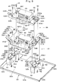
- Fig. 1 to Fig. 10 show a first embodiment of a hybrid-type working machine according to the present invention.
- indicated at 1 is a hybrid-type hydraulic excavator as a representative example of hybrid-type working machines.
- a vehicle body of the hydraulic excavator 1 comprises an automotive lower traveling structure 2 of a crawler type and an upper revolving structure 3 that is mounted on the lower traveling structure 2 to be capable of revolving thereon.
- a working mechanism 4 is provided in the front side of the upper revolving structure 3 to be capable of lifting and tilting thereto, and the hydraulic excavator 1 can perform an excavating operation of earth and sand and the like by using the working mechanism 4.
- the lower traveling structure 2 comprises a track frame having left and right side frames 2A (the left side only is shown), a drive wheel 2B provided on one side of each of the side frames 2A in the front-rear direction (length direction), an idler wheel 2C provided on the other side thereof in the front-rear direction and a crawler belt 2D wound around and between the drive wheel 2B and the idler wheel 2C.
- the left and right drive wheels 2B are driven by left and right traveling hydraulic motors 2E, 2F (refer to Fig. 10 ) to drive the crawler belts 2D for rotation, thus causing the hydraulic excavator 1 to travel.
- the working mechanism 4 comprises a boom 4A mounted on a front part side of a revolving frame 5 to be described later to be capable of lifting and tiling thereto, an arm 4B rotatably mounted on a tip end side of the boom 4A, a bucket 4C rotatably mounted on a tip end side of the arm 4B, and a boom cylinder 4D, an arm cylinder 4E and a bucket cylinder 4F, which are respectively composed of hydraulic cylinders for driving them.
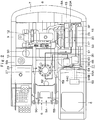
- the upper revolving structure 3 comprises the revolving frame 5 as a base, a cab 6, a counterweight 7, an engine 8, a hydraulic pump 9, an assist generator motor 12, a heat exchanger 13, an electricity storage device 25, a revolving motor 27 and an inverter unit 31, which will be described later, mounted on the revolving frame 5.
- the cab 6 defining an operator's room is provided in a front part and left side of the revolving frame 5.
- An operator's seat on which an operator sits is provided in the cab 6, and a traveling operation lever and a working operation lever (both are not shown) are provided in the periphery of the operator's seat.
- the counterweight 7 is provided in a rear end side of the revolving frame 5 to act as a weight balance to the working mechanism 4.
- the engine 8 is positioned in the front side of the counterweight 7 and is disposed in the rear side of the revolving frame 5.
- the engine 8 is mounted on the revolving frame 5 in a horizontal state where an axis line of a crank shaft (not shown) extends in the left-right direction.
- the hydraulic pump 9 and the assist generator motor 12, which will be described later, are mounted in the right side of the engine 8 in one side in the left-right direction.
- a suction type cooling fan 8A is mounted in the left side of the engine 8 in the other side in the left-right direction (at the opposite side to the hydraulic pump 9).
- the cooling fan 8A is driven/rotated by the engine 8 to suck outside air from an air inlet port 24A formed in a left rear side door 24 to be described later. As shown in Fig. 3 , this outside air is supplied to the engine 8, and the heat exchanger 13 and the electricity storage device 25, which will be described later, and the like as cooling air F.
- the hydraulic pump 9 is mounted in the right side (output side) of the engine 8.
- the hydraulic pump 9 is driven by the engine 8 to supply operating pressurized oil to various kinds of hydraulic actuators including the left and right traveling hydraulic motors 2E, 2F, the respective cylinders 4D, 4E, 4F and a revolving hydraulic motor 28 to be described later, which are mounted on the hydraulic excavator 1.
- a hydraulic oil tank 10 is provided in the front side of the hydraulic pump 9.
- the hydraulic oil tank 10 reserves therein hydraulic oil to be supplied to the hydraulic actuators.
- a control valve 11 (refer to Fig. 10 ) is composed of a collector of a plurality of directional control valves, and controls directions of the pressurized oil to be supplied to the various kinds of hydraulic actuators from the hydraulic pump 9 in response to an operation of the operation lever disposed in the cab 6.
- the assist generator motor 12 is mounted in the right side of the engine 8 together with the hydraulic pump 9.
- the assist generator motor 12 configures a first electric motor according to the present invention.
- the assist generator motor 12 is driven by the engine 8 to generate power or assists in a drive of the engine 8 by supply of power from the electricity storage device 25 to be described later. That is, the assist generator motor 12 has a function of an electric generator that is driven by the engine 8 to generate power and a function of an electric motor that assists in a drive of the engine 8 by supply of power from the electricity storage device 25 to be described later.
- the heat exchanger 13 is positioned in the left side of the engine 8 and is mounted on the revolving frame 5. As shown in Fig. 3 , the heat exchanger 13 is positioned upstream side of the cooling fan 8A in the flow direction of the cooling air F.
- the heat exchanger 13 is configured as a single unit including a support frame 14 mounted on the revolving frame 5, an intercooler 15 assembled to the support frame 14, a radiator 16 for engine, an oil cooler 17, a condenser 18 for air conditioner, a fuel cooler 19 and a radiator 20 for hybrid equipment.
- the support frame 14 comprises a front partition plate 14A that is disposed in the front side of the heat exchanger 13 (closer to the cab 6) and extends in the left-right direction and in the upper-lower direction, a rear partition plate 14B that is disposed in the rear side of the heat exchanger 13 along a left front surface part of the counterweight 7 and extends in the left-right direction and in the upper-lower direction, and a connecting member 14C that extends in the front-rear direction to connect upper parts of the front and rear partition plate 14A, 14B and covers upper parts of the intercooler 15, the radiator 16 for engine and the oil cooler 17.
- the intercooler 15 for cooling air (compressed air) compressed by a turbocharger, the radiator 16 for engine for cooling engine cooling water, the oil cooler 17 for cooling hydraulic oil, the condenser 18 for air conditioner for cooling a cooling medium for air conditioner and the fuel cooler 19 for cooling fuel are assembled on the support frame 14.
- the radiator 20 for hybrid equipment is incorporated on the support frame 14 to cool cooling water for hybrid equipment as a cooling medium for hybrid equipment.
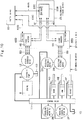
- the cooling water for hybrid equipment cools the electricity storage device 25, first and second inverters 46, 55 and a revolving electric motor 29, which configure the hybrid equipment to be described later. That is, as shown in an arrow in Fig. 2 , the cooling water for hybrid equipment cooled by the radiator 20 for hybrid equipment is supplied to the electricity storage device 25 by a pump 20A and circulates into the radiator 20 for hybrid equipment via the first and second inverters 46, 55 and the revolving electric motor 29.
- the assist generator motor 12 is cooled by engine cooling water.
- the heat exchanger 13 cools the cooling water for hybrid equipment, the compressed air, the engine cooling water, the hydraulic oil, the cooling medium for air conditioner, and the fuel respectively by supply of the outside air (cooling air F) sucked by the cooling fan 8A to the radiator 20 for hybrid equipment, the condenser 18 for air conditioner, the fuel cooler 19, the intercooler 15, the radiator 16 for engine and the oil cooler 17.
- a housing cover 21 is positioned in the front side of the counterweight 7 and is provided on the revolving frame 5.
- the housing cover 21 covers the engine 8, the hydraulic pump 9, the assist generator motor 12, the heat exchanger 13 and the like.
- an upper side of the housing cover 21 comprises an upper surface plate 22 and an engine cover 22A.
- a left side of the housing cover 21 comprises a left front side door 23 disposed on the rear side of the cab 6 and the left rear side door 24 disposed between the left front side door 23 and the counterweight 7.
- the air inlet port 24A for sucking outside air as cooling air F is provided in the left rear side door 24.
- the left front side door 23 opens/closes at the time of performing a maintenance work of the first and second inverters 46, 55 to be described later and the like.
- the left rear side door 24 opens/closes at the time of performing a maintenance work of the heat exchanger 13 and the like.
- a right side of the housing cover 21 comprises a right side door (not shown) disposed between the hydraulic oil tank 10 and the counterweight 7.
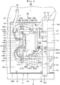
- the electricity storage device 25 performs charge or discharge of power, and the electricity storage device 25 is disposed upstream side of the heat exchanger 13 in the flow direction of cooling air F supplied to the heat exchanger 13.
- the electricity storage device 25 comprises a lithium ion cell, for example, and is mounted on the revolving frame 5.
- the electricity storage device 25 stores power generated by the assist generator motor 12 and regeneration power generated by the revolving electric motor 29 to be described later by deceleration of a revolving operation (regeneration operation) of the upper revolving structure 3 or discharges (supplies) the stored power to the assist generator motor 12 and the revolving electric motor 29.
- the electricity storage device 25 may use, for example, a capacitor of an electrical double layer other than the lithium ion cell.
- a chopper (not shown) is provided between the electricity storage device 25 and cables 51, 60 (DC bus) for electricity storage device to be connected thereto and a voltage of the DC bus is kept to be constant by the chopper.
- the electricity storage device 25 comprises a cubic casing 25A in which a plurality of battery modules are accommodated and a connecting box (junction box) 25B that is composed of a box smaller than the casing 25A and is mounted on the casing 25A.
- a water jacket (not shown) in which cooling water circulates is provided in the casing 25A.
- the connecting box 25B establishes connection between the cables 51, 60 for electricity storage device extending from the first and second inverters 46, 55 to be described later and a terminal of the electricity storage device 25.
- an electrical circuit including a control part 25C for controlling charge/discharge of the electricity storage device 25 based upon signals (command signals) from a control device 63 to be described later is accommodated inside the connecting box 25B.
- a first cable connecting port 25D and a second cable connecting port 25E are provided on a front side surface 25B1 of the connecting box 25B to line up in the left-right direction.
- the cable 51 for electricity storage device for connection to the first inverter 46 is connected to the first cable connecting port 25D.
- the cable 60 for electricity storage device for connection to the second inverter 55 is connected to the second cable connecting port 25E.
- an extension part 25B3 is provided on a rear side surface 25B2 of the connecting box 25B to be positioned in the intermediate part thereof in the left-right direction and extend backward.
- a disconnecting switch 26 is provided in the extension part 25B3 to establish or block power distribution between the electricity storage device 25 and the first and second inverters 46, 55. An operator or a serviceman operates the disconnecting switch 26, thus making it possible to manually stop power supply to the assist generator motor 12 or the revolving electric motor 29 to be described later from the electricity storage device 25 at the maintenance work, for example.
- the revolving motor 27 is provided in the central part of the revolving frame 5.
- the revolving motor 27 revolves the upper revolving structure 3 to the lower traveling structure 2.
- the revolving motor 27 comprises the revolving hydraulic motor 28 driven by the pressurized oil supplied from the hydraulic pump 9 and the revolving electric motor 29, which will be described later, mounted on the revolving hydraulic motor 28.
- the revolving electric motor 29 revolves the upper revolving structure 3 on the lower traveling structure 2 in cooperation with the revolving hydraulic motor 28.
- the revolving electric motor 29 configures a second electric motor according to the present invention.
- the water jacket in which cooling water circulates is formed in the casing as an outer shell of the revolving electric motor 29 (any thereof is not shown).
- the revolving electric motor 29 is driven by supply of power stored in the electricity storage device 25 to revolve the upper revolving structure 3.
- the revolving electric motor 29 generates regeneration power by a regeneration operation when the upper revolving structure 3 decelerates and supplies the regeneration power to the electricity storage device 25.
- the revolving electric motor 29 has a function of an electric motor that revolves the upper revolving structure 3 by supply of power from the electricity storage device 25 via the cable 59 for revolving electric motor to be described later, and a function of an electric generator that converts kinetic energy of the upper revolving structure 3 into electrical energy at the time of deceleration of a revolving the upper revolving structure 3.
- the regeneration power generated by the revolving electric motor 29 is supplied to the electricity storage device 25 via the cable 59 for revolving electric motor and stored in the electricity storage device 25.
- a utility room 30 is formed on the rear side of the cab 6.
- the utility room 30 is defined by a rear surface of the cab 6, the upper surface plate 22 and the left front side door 23 configuring the housing cover 21 and the front partition plate 14A configuring the support frame 14 of the heat exchanger 13.
- a lower side of the utility room 30 is closed by a floor plate 32 to be described later, and an inverter assembly 36 to be described later is mounted on the floor plate 32.
- the inverter unit 31 is formed by integrally uniting the first inverter 46 and the second inverter 55 to be described later.
- the inverter unit 31 comprises the floor plate 32, the vibration isolating members 35 and the inverter assembly 36 to be described later.
- the floor plate 32 configures a part of the revolving frame 5, and closes the lower side of the utility room 30.
- the floor plate 32 becomes a base of the inverter unit 31.
- the floor plate 32 is formed in a rectangular tray shape as a whole by a bottom plate part 32A closing the lower side of the utility room 30 between a left vertical plate 5B and a left side frame 5F and an outer frame part 32B bent upward from an outer peripheral edge of the bottom plate part 32A.
- Four corner parts of the bottom plate part 32A are respectively provided with bolt through holes 32C.
- the floor plate 32 is mounted on the revolving frame 5 by screwing bolts 34 inserted in the bolt through holes 32C into a bottom plate 5A or a floor plate mounting part (not shown) provided in the left side frame 5F.
- two platforms 33 are disposed to be spaced from each other in the left-right direction to rise upward from the bottom plate part 32A.
- the vibration isolating members 35 lining up in the front-rear direction are respectively disposed on an upper surface 33A of each of the platforms 33.
- each of the vibration isolating members 35 elastically supports a support bracket 37 to be described later on the revolving frame 5 to suppress vibrations of the upper revolving structure 3 from directly transmitting to the first and second inverters 46, 55.
- Each of the vibration isolating members 35 comprises an elastic body 35A that is formed by using a flexible material (elastic material) such as rubber and the like and is mounted on the upper surface 33A of the platform 33 and a support bracket mounting part 35B that is formed by using a plate material in a substantially elliptic shape and is mounted on an upper surface of the elastic body 35A.
- Bolt through holes 35B1 are provided in both end sides of each of the support bracket mounting parts 35B in the front-rear direction, and bolts 42 for mounting the inverter assembly 36 to be described later on the vibration isolating members 35 are inserted in the bolt through holes 35B1.
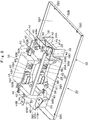
- inverter assembly 36 including the support bracket 37, the first inverter 46 and the second inverter 55.
- the inverter assembly 36 is elastically supported on the vibration isolating members 35.
- the inverter assembly 36 comprises the support bracket 37, the first inverter 46, the second inverter 55, a connecting line 54 and the like, which will be described later, and is formed by sub-assembling them as one assembly.
- the first inverter 46 and the second inverter 55 are sub-assembled by using the support bracket 37.
- the support bracket 37 is mounted on the vibration isolating members 35, and the support bracket 37 supports the first inverter 46 and the second inverter 55 together. Therefore, the first inverter 46 and the second inverter 55 are elastically supported together on the vehicle body (revolving frame 5) by using the support bracket 37. That is, as shown in Fig. 6 to Fig.9 , the support bracket 37 supports the first inverter 46 and the second inverter 55 to line up in the upper-lower direction. Therefore, the support bracket 37 comprises a lower side mounting member 38 and an upper side mounting member 43, which will be described later.
- the lower side mounting member 38 is positioned in the lower side in the upper-lower direction to mount the second inverter 55 to be described later.
- the lower side mounting member 38 is positioned between the platforms 33 disposed on the bottom plate part 32A of the floor plate 32 to be spaced from each other in the left-right direction, and comprises a flat plate 38A made up of a rectangular plate material, left and right rising plates 38B rising upward respectively from both ends of the flat plate 38A in the left-right direction, and left and right flange plates 38C extending outward (to the opposite side to the flat plate 38A) respectively from upper ends of the left and right rising plates 38B in the left-right direction.
- the flat plate 38A has a length dimension in the front-rear direction that is set to be substantially equal to a length dimension in the front-rear direction of a pair of the platforms 33, and is in a position lower than the upper surface 33A of each of the platforms 33.
- the flat plate 38A is provided with four female holes (not shown), in which bolts 56 for mounting the second inverter 55 to be described later are screwed, by using back nuts, back screw seats and the like, for example.
- An inlet line fixing projection piece 39A as a line fixing tool for fixing an inlet line 53 to be described later and an outlet line fixing projection piece 39B as a line fixing tool for fixing an outlet line 62 to be described later are provided on a rear end side of the flat plate 38A and in the left side as the other end in the left-right direction (refer to Fig. 4 ).
- the inlet line 53 is fixed to the inlet line fixing projection piece 39A by using a clamp 39A1.
- the outlet line 62 is fixed to the outlet line fixing projection piece 39B by using a clamp 39B1.
- the left and right rising plates 38B facing each other in the left-right direction and a height dimension thereof is set to be greater than a height dimension of the second inverter 55 to be described later and slightly smaller than a height dimension from the bottom plate part 32A of the floor plate 32 to the upper surface of the support bracket mounting part 35B in the vibration isolating member 35.
- a connecting line fixing projection piece 40 on which a connecting line 54 to be described later is fixed is provided on a front end side of the rising plate 38B in the right side as one side in the left-right direction.
- the connecting line 54 is fixed to the connecting line fixing projection piece 40 through a clamp 40A.
- a cable fixing projection piece 41A for electricity storage device is formed in a reverse U-letter shape and is provided on a front end side of the left (other side) flange plate 38C, the cable fixing projection piece 41A acting as a cable fixing tool for fixing a cable 60 for electricity storage device to be described later.
- the cable 60 for electricity storage device is fixed to the cable fixing projection piece 41A for electricity storage device by a clamp 41A1.
- a cable fixing projection piece 41B for revolving electric motor is provided on a front end side of the right (one side) flange plate 38C, the cable fixing projection piece 41B being formed in a plate shape inclining obliquely downward from the flange plate 38C to the flat plate 38A and acting as a cable fixing tool for fixing a cable 59 for revolving electric motor to be described later.
- the cable 59 for revolving electric motor is fixed to the cable fixing projection piece 41B for revolving electric motor by a clamp 41B1.
- the left and right flange plates 38C each are provided with four female screw holes 38C1 in the front-rear direction.
- the female screw holes 38C1 are disposed in positions corresponding to the bolt through holes 35B1 provided in the support bracket mounting part 35B of each of the vibration isolating members 35.
- the female screw holes 38C1 are formed on an upper surface side of the flange plate 38C by using front nuts, front screw seats and the like, for example.
- Two female screw holes 38C2 are formed in each of the left and right flange plates 38C to be spaced from each other in the front-rear direction, the two female screw holes 38C2 being provided in positions different from those of the female screw holes 38C1 respectively and closer to the inward side in the left-right direction than the female screw holes 38C1 (closer to the rising plate 38B).
- Bolts 45 are screwed into the respective female screw holes 38C2 to mount an upper side mounting member 43 to be described later.
- the respective female screw holes 38C2 are formed on a lower surface side of the flange plate 38C by using back nuts, back screw seats and the like, for example.
- a lower side mounting member 38 is mounted on the four vibration isolating members 35. Therefore, the lower side mounting member 38 has the left and right flange plates 38C that are placed respectively on the support bracket mounting parts 35B of the left and right vibration isolating members 35. In this state, the two bolts 42 are inserted into the respective bolt through holes 35B1 respectively from a lower surface side of each of the support bracket mounting parts 35B, and each of the bolts 42 is screwed into each of the female screw holes 38C1 of the lower side mounting member 38.
- a height dimension of each of the left and right rising plates 38B is set to be slightly smaller than a height dimension from the bottom plate part 32A of the floor plate 32 to an upper surface of the support bracket mounting part 35B of the vibration isolating member 35. Therefore, the flat plate 38A is in a non-contact state with the bottom plate part 32A, that is, in a state of being lifted by the vibration isolating members 35 (in a state of being separated from the bottom plate part 32A in the upper-lower direction). Therefore, the lower side mounting member 38 is elastically supported to the revolving frame 5 by the vibration isolating members 35.
- the upper side mounting member 43 is positioned in the upper side from the lower side mounting member 38 and mounts the first inverter 46 to be described later thereon.
- the upper side mounting member 43 comprises a flat plate 43A extending between the left and right flange plates 38C of the lower side mounting member 38 and front and rear protrusion plates 43B protruding upward from both ends of the flat plate 43A in the front-rear direction.
- a length dimension of the flat plate 43A in the left-right direction is set to be slightly greater than a length dimension between the left and right rising plates 38B of the lower side mounting member 38.
- the flat plate 43A is provided with four female screw holes (not shown) into which bolts 47 for mounting the first inverter 46 to be described later are screwed, the four female screw holes being formed by using back nuts, back screw seats and the like.
- Bolt through holes 43A1 are respectively provided on both end sides of the flat plate 43A in the left-right direction in positions corresponding to the respective female screw holes 38C2 formed in the left and right flange plates 38C of the lower side mounting member 38.
- a cable fixing projection piece 44A for electricity storage device formed in a reverse U-letter shape is provided on the left end side (other end side) of the flat plate 43A and between the front and rear Bolt through holes 43A1.
- the cable fixing projection piece 44A for electricity storage device configures a cable fixing tool for fixing a cable 51 for electricity storage device to be described later. As shown in Fig. 4 and Fig. 6 , the cable 51 for electricity storage device is fixed to the cable fixing projection piece 44A for electricity storage device by using a clamp 44A1.
- a cable fixing projection piece 44B for assist generator motor is provided on the right end side (one end side) of the front protrusion plate 43B, the cable fixing projection piece 44B for assist generator motor protruding upward from the protrusion plate 43B and being formed in a reverse L-letter shape by bending the upper end thereof forward.
- the cable fixing projection piece 44B for assist generator motor is configured as a cable fixing tool for fixing a cable 50 for assist generator motor to be described later. As shown in Fig. 4 and Fig. 6 , the cable 50 for assist generator motor is fixed to the cable fixing projection piece 44B for assist generator motor by using a clamp 44B1.
- the upper side mounting member 43 is mounted on the lower side mounting member 38 by inserting the respective bolts 45 into the respective Bolt through holes 43A1 from an upper surface side of the flat plate 43A to be screwed into the respective female screw holes 38C2 of the left and right flange plates 38C in a state where the flat plate 43A is placed on the left and right flange plates 38C of the lower side mounting member 38.
- the upper side mounting member 43 is elastically supported to the respective vibration isolating members 35 through the lower side mounting member 38.
- the first inverter 46 is mounted on the flat plate 43A of the upper side mounting member 43.
- the first inverter 46 controls an operation of the assist generator motor 12.
- the first inverter 46 is mounted on the flat plate 43A of the upper side mounting member 43 by screwing the bolts 47 into female screw holes (not shown) formed in the flat plate 43A of the upper side mounting member 43.
- a first cable connecting port 48 and a second cable connecting port 49 lining up in the left-right direction are provided on a front surface 46A side of a casing as an outer shell of the first inverter 46.
- the cable 50 (three-phase AC cable) for assist generator motor is removably mounted on the first cable connecting port 48 positioned in the right side as one side in the left-right direction for connection between the assist generator motor 12 and the first inverter 46.
- a halfway portion of the cable 50 for assist generator motor is fixed to the cable fixing projection piece 44B for assist generator motor provided on the upper side mounting member 43 through the clamp 44B1. Therefore, the cable 50 for assist generator motor is in the same vibration system with the support bracket 37, and vibrates together with the first inverter 46 fixed on the support bracket 37. Therefore, the cable 50 for assist generator motor is less subjected to a force of pulling (removing) it out of the first cable connecting port 48. Accordingly, the cable 50 for assist generator motor is prevented from pulling and falling down out of the first cable connecting port 48.
- the cable 51 (DC bus) for electricity storage device is removably mounted on the second cable connecting port 49 positioned in the left side as the other side in the left-right direction for connection between the electricity storage device 25 and the first inverter 46. That is, the cable 51 for electricity storage device has one end side mounted on the first cable connecting port 25D provided in the connecting box 25B in the electricity storage device 25 and the other end side mounted on the second cable connecting port 49 of the first inverter 46.
- a halfway portion of the cable 51 for electricity storage device is fixed to the cable fixing projection piece 44A for electricity storage device provided on the upper side mounting member 43 by using the clamp 44A1. Accordingly, the cable 51 for electricity storage device is in the same vibration system with the first inverter 46 and is prevented from pulling and falling down out of the second cable connecting port 49.
- the first inverter 46 converts the power generated by the assist generator motor 12 into DC power, and supplies the DC power to the electricity storage device 25 through the cable 51 for electricity storage device.
- the first inverter 46 converts the DC power supplied from the electricity storage device 25 via the cable 51 for electricity storage device into three-phase AC power, and supplies the three-phase AC power to the assist generator motor 12 via the cable 50 for assist generator motor.
- a cooling line connector 52A is provided on a left surface 46B side of the casing in the first inverter 46, and an inlet line 53 is connected to the cooling line connector 52A. That is, a downstream end side of the inlet line 53 for inflow of the cooling water for hybrid equipment flowing out from the electricity storage device 25 into the casing of the first inverter 46 is mounted on the cooling line connector 52A.
- the inlet line 53 is provided for connection between the electricity storage device 25 and the first inverter 46 so that circulation of the cooling water for hybrid equipment therebetween is made possible, and an upstream end side of the inlet line 53 is connected to the electricity storage device 25. A halfway portion of the inlet line 53 is fixed to the inlet line fixing projection piece 39A provided on the lower side mounting member 38 by using the clamp 39A1. Accordingly, the inlet line 53 is in the same vibration system with the first inverter 46 and is prevented from pulling and falling down out of the cooling line connector 52A.
- a cooling line connector 52B is provided on a right surface 46C side of the casing in the first inverter 46, and the connecting line 54 is connected to the cooling line connector 52B. That is, an upstream end side of the connecting line 54 for causing the cooling water for hybrid equipment flowing out from the first inverter 46 to flow toward the second inverter 55 is mounted on the cooling line connector 52B. A halfway portion of the connecting line 54 is fixed to the connecting line fixing projection piece 40 provided on the lower side mounting member 38 by using the clamp 40A.
- the connecting line 54 is provided for connection between the first inverter 46 and the second inverter 55 so that circulation of the cooling water for hybrid equipment therebetween is made possible.
- a plurality of switching elements composed of a transistor, an insulating gate bipolar transistor (IGBT) and the like are accommodated in the casing of the first inverter 46.
- An on/off operation of each of the switching elements is controlled by a control part 46D.
- a signal line 64B to be described later for connection to a control device 63 to be described later is connected to the control part 46D.
- a water jacket (not shown) in which cooling water for hybrid equipment circulates is formed in the casing of the first inverter 46. The water jacket is connected to the inlet line 53 through the cooling line connector 52A, and is connected to the connecting line 54 through the cooling line connector 52B.
- the second inverter 55 is mounted on the flat plate 38A of the lower side mounting member 38.
- the second inverter 55 controls an operation of the revolving electric motor 29.
- the second inverter 55 is mounted by screwing the bolts 56 into female screw holes (not shown) formed in the flat plate 38A of the lower side mounting member 38. In this case, the second inverter 55 is positioned right under the first inverter 46.
- the second inverter 55 is an inverter that is composed of components in common with those of the first inverter 46 and has an identical configuration to the first inverter 46.
- the identical configuration does not indicate the completely identical configuration only, but includes the concept that a basic configuration thereof is identical. That is, the identical configuration indicates the extent that when a configuration of the first inverter 46 is compared with a configuration of the second inverter 55, even if a slight difference exists therebetween, it does not make any problem upon using the first inverter 46 and the second inverter 55 as common components, for example.
- a first cable connecting port 57 and a second cable connecting port 58 lining up in the left-right direction are provided on a front surface 55A side of a casing as an outer shell of the second inverter 55.
- the cable 59 (three-phase AC cable) for revolving electric motor is removably mounted on the first cable connecting port 57 positioned in the right side as one side in the left-right direction for connection between the revolving electric motor 29 and the second inverter 55.
- a halfway portion of the cable 59 for revolving electric motor is fixed to the cable fixing projection piece 41B for revolving electric motor provided on the lower side mounting member 38 by using the clamp 41B1.
- the cable 59 for revolving electric motor is in the same vibration system with the second inverter 55. Therefore, the cable 59 for revolving electric motor is prevented from pulling and falling down out of the first cable connecting port 57.
- the cable 60 (DC bus) for electricity storage device is removably mounted on the second cable connecting port 58 positioned in the left side as the other side in the left-right direction for connection between the electricity storage device 25 and the second inverter 55. That is, the cable 60 for electricity storage device has one end side mounted on the second cable connecting port 25E provided in the connecting box 25B in the electricity storage device 25 and the other end side mounted on the second cable connecting port 58 of the second inverter 55.
- a halfway portion of the cable 60 for electricity storage device is fixed to the cable fixing projection piece 41A for electricity storage device provided on the lower side mounting member 38 by using the clamp 41A1. Accordingly, the cable 60 for electricity storage device is in the same vibration system with the second inverter 55 and is prevented from pulling and falling down out of the second cable connecting port 58.
- the second inverter 55 converts the power (regeneration power) generated by the revolving electric motor 29 into DC power, and supplies the DC power to the electricity storage device 25 through the cable 60 for electricity storage device.
- the second inverter 55 converts the DC power supplied from the electricity storage device 25 via the cable 60 for electricity storage device into three-phase AC power, and supplies the three-phase AC power to the revolving electric motor 29 via the cable 59 for revolving electric motor.
- a cooling line connector 61A is provided on a left surface 55B side of the casing in the second inverter 55, and the outlet line 62 is connected to the cooling line connector 61A. That is, an upstream end side of the outlet line 62 for guiding the cooling water for hybrid equipment flowing out from the second inverter 55 toward the revolving electric motor 29 is mounted on the cooling line connector 61A. A halfway portion of the outlet line 62 is fixed to an outlet line fixing projection piece 39B provided on the lower side mounting member 38 by using a clamp 39B1. Accordingly, the outlet line 62 is in the same vibration system with the second inverter 55 and is prevented from pulling and falling down out of the cooling line connector 61A.
- a cooling line connector 61B is provided on a right surface 55C side of the casing in the second inverter 55, and the connecting line 54 is connected to the cooling line connector 61B. That is, a downstream end side of the connecting line 54 for causing the cooling water for hybrid equipment flowing out from the first inverter 46 to flow toward the second inverter 55 is mounted on the cooling line connector 61B.
- a plurality of switching elements composed of a transistor, an insulating gate bipolar transistor (IGBT) and the like are accommodated in the casing of the second inverter 55.
- An on/off operation of each of the switching elements is controlled by a control part 55D.
- a signal line 64C to be described later for connection to a control device 63 to be described later is connected to the control part 55D.
- a water jacket (not shown) in which cooling water for hybrid equipment circulates is formed in the casing of the second inverter 55. The water jacket is connected to the outlet line 62 through the cooling line connector 61A, and is connected to the connecting line 54 through the cooling line connector 61B.
- the control device 63 controls operations of the electricity storage device 25, the assist generator motor 12, the revolving electric motor 29 and the like.
- the control device 63 and the control part 25C of the electricity storage device 25 are connected through a signal line 64A.
- the control device 63 and the control part 46D of the first inverter 46 are connected through a signal line 64B.
- the control device 63 and the control part 55D of the second inverter 55 are connected through a signal line 64C.
- the control device 63 controls the charge or discharge by the electricity storage device 25 by outputting a control signal to the control part 25C of the electricity storage device 25. In addition thereto, the control device 63 outputs control signals to the control parts 46D, 55D of the first and second inverters 46, 55 to control operations of the assist generator motor 12 and the revolving electric motor 29.
- the hybrid-type hydraulic excavator 1 has the configuration as described above, and next, an explanation will be made of an operation thereof.
- the hydraulic pump 9 and the assist generator motor 12 are driven by the engine 8.
- the pressurized oil delivered from the hydraulic pump 9 is supplied to the left and right traveling hydraulic motors 2E, 2F, the revolving hydraulic motor 28, and the boom cylinder 4D, the arm cylinder 4E and the bucket cylinder 4F in the working mechanism 4 in response to operations of an operation lever (not shown) provided in the cab 6.
- the hydraulic excavator 1 performs a traveling operation by the lower traveling structure 2, a revolving operation by the upper revolving structure 3, an excavating operation by the working mechanism 4 and the like.
- the assist generator motor 12 when output torque of the engine 8 is greater than drive torque of the hydraulic pump 9 at the operating of the hydraulic excavator 1, the assist generator motor 12 is driven as an electric generator by the extra toque. Therefore, the assist generator motor 12 generates AC power. The AC power is converted into DC power by the first inverter 46, which is then stored in the electricity storage device 25.
- the assist generator motor 12 when the output torque of the engine 8 is smaller than the drive torque of the hydraulic pump 9, the assist generator motor 12 is driven as an electric motor by the power from the electricity storage device 25 to assist in a drive of the hydraulic pump 9 by the engine 8.
- the revolving electric motor 29 is driven by supply of the power stored in the electricity storage device 25 to revolve the upper revolving structure 3 on the lower traveling structure 2 in cooperation with the revolving hydraulic motor 28.
- the revolving electric motor 29 generates AC power (regeneration power) by a regeneration operation when the upper revolving structure 3 revolves and decelerates, and the AC power is converted into DC power by the second inverter 55, which is then stored in the electricity storage device 25.
- the assist generator motor 12, the revolving electric motor 29 and the like are driven at the operating of the hydraulic excavator 1, the first inverter 46 for controlling the assist generator motor 12 and the second inverter 55 for controlling the revolving electric motor 29 generate heat to increase temperatures thereof.
- the electricity storage device 25 performs charge and discharge thereof according to operating situations of the hydraulic excavator 1 to generate heat and increase temperatures thereof.
- the assist generator motor 12 is cooled by engine cooling water cooled by the radiator 16 for engine.
- the electricity storage device 25, the first inverter 46, the second inverter 55 and the revolving electric motor 29 are cooled by cooling water for hybrid equipment cooled by the radiator 20 for hybrid equipment.
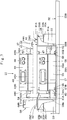
- the cooling water for hybrid equipment cooled by the radiator 20 for hybrid equipment is circulated in the order of the electricity storage device 25, the first inverter 46, the second inverter 55 and the revolving electric motor 29 by the pump 20A. That is, the cooling water for hybrid equipment having flowed out from the electricity storage device 25 flows into the first inverter 46 through the inlet line 53. The cooling water for hybrid equipment having flowed out from the first inverter 46 flows into the second inverter 55 through the connecting line 54. The cooling water for hybrid equipment having flowed out from the second inverter 55 flows into the revolving electric motor 29 through the outlet line 62. Thereby, the electricity storage device 25, the first inverter 46, the second inverter 55 and the revolving electric motor 29 are kept in an appropriate temperature.
- the electricity storage device and the inverter are united to be configured as the electric unit. Therefore, when the electricity storage device or the inverter is replaced, both the electricity storage device and the inverter are required to be integrally removed from the vehicle body. In this case, since a plurality of cables, lines and the like are mounted to the electricity storage device and the inverter, the replacement works including the removal work of them become burdensome. As a result, there is a problem that workability on the replacement work deteriorates.
- the first inverter 46 and the second inverter 55 are mounted on the support bracket 37, which is elastically supported on the revolving frame 5 through the four vibration isolating members 35, in the position different from the position where the electricity storage device 25 is mounted.
- the electricity storage device 25 is disposed in front of the counterweight 7 and in the front side (the left side in the left-right direction of the vehicle body) of the heat exchanger 13.
- the first inverter 46 and the second inverter 55 are disposed in the position separated from the electricity storage device 25, that is, in the utility room 30 positioned in front of the electricity storage device 25, in a state of being mounted on the support bracket 37. In this case, the first inverter 46 and the second inverter 55 are together supported to the revolving frame 5 by using the one support bracket 37.
- the first inverter 46 and the second inverter 55 are mounted compactly on the revolving frame 5. Along with this, it is possible to improve workability on the replacement work of the first and second inverters 46, 55 and the electricity storage device 25.
- the support bracket 37 elastically supports the first and second inverters 46, 55 together on the revolving frame 5 through the four vibration isolating members 35, it is not necessary to provide the vibration isolating member to each of the first inverter 46 and the second inverter 55. Therefore, it is possible to improve the assembling performance of the first inverter 46 and the second inverter 55 and reduce the costs.
- the support bracket 37 is composed of the lower side mounting member 38 and the upper side mounting member 43 to be formed as an upper-lower layered structure, wherein the second inverter 55 is mounted on the lower side mounting member 38 and the first inverter 46 is mounted on the upper side mounting member 43.
- the first inverter 46 and the second inverter 55 can be mounted compactly on the revolving frame 5.
- the second inverter 55 is mounted on the flat plate 38A of the lower side mounting member 38 by the bolts 56.
- the first inverter 46 is mounted on the flat plate 43A of the upper side mounting member 43 by the bolts 47.
- the flat plate 43A of the upper side mounting member 43 is placed on the flange plates 38C of the lower side mounting member 38, and the bolts 45 are screwed into the female screw holes 38C2 of the lower side mounting member 38. Thereby, the lower side mounting member 38 and the upper side mounting member 43 are united.
- the one end side (upstream end side) of the connecting line 54 is connected to the cooling line connector 52B of the first inverter 46, and the other end side (downstream end side) of the connecting line 54 is connected to the cooling line connector 61B of the second inverter 55.
- the halfway portion of the connecting line 54 is fixed to the connecting line fixing projection piece 40 of the lower side mounting member 38 by using the clamp 40A.
- the inverter assembly 36 is assembled as a subassembly.
- the inverter assembly 36 thus assembled is mounted on the four vibration isolating members 35 provided on the platforms 33 of the floor plate 32 disposed in the utility room 30. That is, the flange plates 38C of the lower side mounting member 38 are placed on the vibration isolating members 35, and the respective bolts 42 are screwed respectively into the female screw holes 38C1 of the lower side mounting member 38. Therefore, the first inverter 46 and the second inverter 55 can be assembled on the revolving frame 5.
- the flat plate 38A of the lower side mounting member 38 is positioned to be lower than a fulcrum point (mounting point or supporting point) between the lower side mounting member 38 and each of the vibration isolating members 35.
- a gravity center height of the inverter assembly 36 can be lowered (low gravity center). More specifically, the gravity center height of the inverter assembly 36 can be substantially equal to the height position of the elastic body 35A of the vibration isolating member 35.
- the cable 50 for assist generator motor mounted on the first cable connecting port 48 of the first inverter 46 is fixed on the cable fixing projection piece 44B for assist generator motor of the upper side mounting member 43.
- the cable 51 for electricity storage device mounted on the second cable connecting port 49 is fixed on the cable fixing projection piece 44A for electricity storage device of the upper side mounting member 43.
- the cable 59 for revolving electric motor mounted on the first cable connecting port 57 of the second inverter 55 is fixed on the cable fixing projection piece 41B for revolving electric motor of the lower side mounting member 38.
- the cable 60 for electricity storage device mounted on the second cable connecting port 58 is fixed on the cable fixing projection piece 41A for electricity storage device.
- the inlet line 53 mounted on the cooling line connector 52A of the first inverter 46 is fixed on the inlet line fixing projection piece 39A of the lower side mounting member 38.
- the outlet line 62 mounted on the cooling line connector 61A of the second inverter 55 is fixed on the outlet line fixing projection piece 39B of the lower side mounting member 38. That is, various kinds of cables (power lines, signal lines and cooling hoses) connected to the first and second inverters 46, 55 are all fixed in the halfway portions on the support bracket 37.
- the connecting line 54 has an upstream side mounted on the cooling line connector 52B of the first inverter 46 and a downstream side mounted on the cooling line connector 61B of the second inverter 55. In this case, the connecting line 54 is fixed on the connecting line fixing projection piece 40 of the lower side mounting member 38.
- the respective cables 50, 51, 59, 60, the inlet line 53, the outlet line 62 and the connecting line 54 are in the same vibration system with the first and second inverters 46, 55.
- the respective cables 50, 51, 59, 60, the inlet line 53, the outlet line 62 and the connecting line 54 are prevented from pulling and falling down out of the first and second inverters 46, 55.
- the first inverter 46 and the second inverter 55 are mounted on the support bracket 37 in the position different from the position where the electricity storage device 25 is mounted. Therefore, the first inverter 46 and the second inverter 55 can be mounted compactly on the revolving frame 5 through the support bracket 37. Along with this, it is possible to improve workability on the replacement work of the first and second inverters 46, 55 and the electricity storage device 25.
- the support bracket 37 can elastically support the first inverter 46 and second inverter 55 together on the revolving frame 5. Accordingly, it is not necessary to provide different vibration isolating members to the first inverter 46 and the second inverter 55 respectively. Therefore, it is possible to improve the assembling performance of the first inverter 46 and the second inverter 55 and reduce the costs.
- the support bracket 37 is of the upper-lower layered structure, and thereby, the first inverter 46 and the second inverter 55 are mounted in a state of being layered (in parallel) in the upper-lower direction. Therefore, the first inverter 46 and the second inverter 55 can be mounted on the revolving frame 5 more compactly.
- the support bracket 37, the first inverter 46, the second inverter 55 and the connecting line 54 are configured as the inverter assembly 36, it is possible to improve handling performance (easiness of handling) of these members. Thereby, it is possible to improve workability of the assembling work or removal work of the first inverter 46 and the second inverter 55 onto or from the revolving frame 5.
- the respective cables 50, 51, 59, 60, the inlet line 53, the outlet line 62 and the connecting line 54 are fixed on the support bracket 37. Accordingly, even if the support bracket 37 elastically supported on the revolving frame 5 vibrates, it is possible to reduce for an external force (force in a direction of removing them from the first inverter 46 or second inverter 55) to be applied to the respective cables 50, 51, 59, 60, the inlet line 53, the outlet line 62 and the connecting line 54.
- the respective cables 50, 51, 59, 60, the inlet line 53, the outlet line 62 and the connecting line 54 can be prevented from pulling and falling down out of the first and second inverters 46, 55 and reliability and stability of the hydraulic excavator 1 can be improved.
- Fig. 11 and Fig. 12 show a second embodiment of the present invention.
- the present embodiment is characterized in that a first inverter is mounted on an upper surface side of an upper side mounting member and a second inverter is mounted on a lower surface side of the upper side mounting member.
- a first inverter is mounted on an upper surface side of an upper side mounting member
- a second inverter is mounted on a lower surface side of the upper side mounting member.
- a support bracket 70 comprises an upper side mounting member 71 and the lower side mounting member 38 according to the first embodiment.
- the support bracket 70 is mounted on the vibration isolating members 35, and this support bracket 70 supports the first inverter 46 and a second inverter 72 together. Therefore, the first inverter 46 and the second inverter 72 are elastically supported to the vehicle body (revolving frame 5) together by using the support bracket 70.
- the support bracket 70 may be composed of the upper side mounting member 71 only.
- the upper side mounting member 71 is positioned in the upper side from the lower side mounting member 38.
- the upper side mounting member 71 corresponds to a mounting member of the present invention. That is, the first inverter 46 and the second inverter 72 to be described later are mounted on the upper side mounting member 71.
- the upper side mounting member 71 comprises a flat plate 71A extending between the left and right flange plates 38C of the lower side mounting member 38 and front and rear protrusion plates 71B protruding upward from both ends of the flat plate 71A in the front-rear direction.
- the first inverter 46 is mounted on an upper surface 71A1 side of the flat plate 71A.
- the second inverter 72 to be described later is mounted on a lower surface 71A2 side of the flat plate 71A.
- the upper side mounting member 71 is mounted on the left and right flange plates 38C of the lower side mounting member 38 by the bolts 45.
- the second inverter 72 is mounted on the upper side mounting member 71, and controls an operation of the revolving electric motor 29.
- the second inverter 72 is an inverter that is composed of components in common with those of the first inverter 46 and has an identical configuration to the first inverter 46.
- the identical configuration does not indicate the completely identical configuration only, but includes the concept that a basic configuration thereof is identical. That is, the identical configuration indicates the extent that when a configuration of the first inverter 46 is compared with a configuration of the second inverter 72, even if a slight difference exists therebetween, it does not make any problem upon using the first inverter 46 and the second inverter 72 as common components, for example.
- the second inverter 72 is mounted on the lower surface 71A2 side of the flat plate 71A in the upper side mounting member 71 in a state of being reversed to the first inverter 46 in the upper-lower direction.
- a first cable connecting port 73 and a second cable connecting port 74 lining up in the left-right direction are provided on a front surface 72A side of a casing as an outer shell of the second inverter 72 (refer to Fig.11 ).
- the cable 59 (three-phase AC cable) for revolving electric motor is removably mounted on the first cable connecting port 73 positioned in the left side (other side) in the left-right direction for connection between the revolving electric motor 29 and the second inverter 72.
- the cable 60 (DC bus) for electricity storage device is removably mounted on the second cable connecting port 74 positioned in the right side (one side) in the left-right direction for connection between the electricity storage device 25 and the second inverter 72.
- a height dimension of the gravity center position can be made to a height substantially equal to a height dimension of a mounting position of each of the left and right vibration isolating members 35.
- the first inverter 46 and the second inverter 72 can be stably mounted on the revolving frame 5.
- the first inverter 46 and the second inverter 72 that are composed of the common components and are formed of the same configuration are mounted on the upper side mounting member 71 in a reversed state to each other in the upper-lower direction. Accordingly, in a state where the first inverter 46 and the second inverter 72 are mounted on the upper side mounting member 71, the gravity center position of a total of the three members can be positioned to a substantially central part of the upper side mounting member 71. As a result, the first inverter 46 and the second inverter 72 can be stably mounted on the revolving frame 5.
- the aforementioned first embodiment is explained by taking a case where the first inverter 46 is mounted on the upper side mounting member 43 and the second inverter 55 is mounted on the lower side mounting member 38, as an example.
- the present invention is not limited thereto, but, for example, the second inverter 55 may be mounted on the upper side mounting member 43, and the first inverter 46 may be mounted on the lower side mounting member 38.
- the aforementioned second embodiment is explained by taking a case where the first inverter 46 is mounted on the upper surface 71A1 side of the upper side mounting member 71 and the second inverter 72 is mounted on the lower surface 71A2 side of the upper side mounting member 71, as an example.
- the present invention is not limited thereto, but, for example, the second inverter 72 may be mounted on the upper surface 71A1 side of the upper side mounting member 71 and the first inverter 46 may be mounted on the lower surface 71A2 side of the upper side mounting member 71.
- the aforementioned second embodiment is explained by taking a case where the upper side mounting member 71 is mounted on the lower side mounting member 38, as an example.
- the present invention is not limited thereto, but, for example, the upper side mounting member 71 may be mounted directly on the left and right vibration isolating members 35 without using the lower side mounting member 38.
- the aforementioned first embodiment is explained by taking a case where the revolving electric motor 29 is used as the second electric motor, as an example.
- the present invention is not limited thereto, but, for example, an electric motor for hydraulic regeneration that generates regeneration power by returning oil from a hydraulic actuator may be used as the second electric motor. The same applies to the second embodiment.
- the revolving motor 27 comprises the revolving hydraulic motor 28 and the revolving electric motor 29, as an example.
- the present invention is not limited thereto, but, for example, the revolving motor may comprise the revolving electric motor only. The same applies to the second embodiment.
- the hydraulic excavator 1 of a crawler type equipped with the crawler belts 2D is used as the hydraulic-type working machine, as an example.
- the present invention is not limited thereto, but, for example, the present invention may be widely applied to various types of working machines such as a wheel-type hydraulic excavator equipped with wheels, a wheel loader, a fork lift and a dump truck and the like.
Claims (5)
- Machine de chantier de type hybride comprenant :un corps de véhicule automoteur (2, 3) doté d'un mécanisme de travail (4) ;un moteur (8) qui est disposé sur ledit corps de véhicule (2, 3) et qui entraîne une pompe hydraulique (9) ;une première motrice électrique (12) qui est entraînée par ledit moteur (8) pour générer une puissance ou qui assiste un entraînement dudit moteur (8) en approvisionnant de la puissance ;un dispositif de stockage d'électricité (25) qui stocke une puissance générée par ladite première motrice électrique (12) ou qui décharge de la puissance à l'intérieur de celle-ci;une deuxième motrice électrique (29) qui est entraînée par une puissance approvisionnée depuis ledit dispositif de stockage d'électricité (25) ou qui approvisionne une puissance de régénération générée par un fonctionnement en régénération vers ledit dispositif de stockage d'électricité (25) ;un premier convertisseur (46) pour commander un fonctionnement de ladite première motrice électrique (12) ; etun deuxième convertisseur (55) pour commander un fonctionnement de ladite deuxième motrice électrique (29),dans laquelleledit premier convertisseur (46) et ledit deuxième convertisseur (55) sont montés sur une monture de support (37) supportée élastiquement sur ledit corps de véhicule (2, 3) dans une position différente d'une position dans laquelle est monté ledit dispositif de stockage d'électricité (25),ledit premier convertisseur (46) et ledit deuxième convertisseur (55) sont reliés par une conduite de raccordement (54) dans laquelle circule un fluide de refroidissement destiné à refroidir ledit premier convertisseur (46) et ledit deuxième convertisseur (55),ladite monture de support (37), ledit premier convertisseur (46), ledit deuxième convertisseur (55) et ladite conduite de raccordement (54) sont configurés en tant qu'assemblage de convertisseur (36),une conduite d'entrée (53) est reliée à un convertisseur parmi le premier convertisseur (46) et ledit deuxième convertisseur (55), ladite conduite d'entrée (53) amenant le fluide de refroidissement destiné à refroidir ledit premier convertisseur (46) et ledit deuxième convertisseur (55) à s'écouler jusque dans ledit un convertisseur, et une conduite de sortie (62) est reliée audit autre convertisseur, ladite conduite de sortie (62) amenant le fluide de refroidissement ayant refroidi ledit premier convertisseur (46) et ledit deuxième convertisseur (55) à s'écouler vers l'extérieur,une pluralité de câbles (50, 51, 59, 60) sont connectés respectivement audit premier convertisseur (46) et audit deuxième convertisseur (55),ladite monture de support (37) est dotée d'outils de fixation de câble (41A, 41B, 44A, 44B) destinés à fixer ladite pluralité de câbles (50, 51, 59, 60) respectivement et d'outils de fixation de conduite (39A, 39B) destinés à fixer ladite conduite d'entrée (53) et ladite conduite de sortie (62) respectivement,caractérisée en ce queladite monture de support (37) comprend :un élément de montage de côté inférieur (38) qui est positionné dans un côté inférieur dans une direction haut/bas et sur lequel est monté un convertisseur parmi ledit premier convertisseur (46) et ledit deuxième convertisseur (55), etun élément de montage de côté supérieur (43) qui est positionné dans un côté supérieur par rapport audit élément de montage de côté inférieur (38) et sur lequel est monté l'autre convertisseur.
- Machine de chantier de type hybride comprenant :un corps de véhicule automoteur (2, 3) doté d'un mécanisme de travail (4) ;un moteur (8) qui est disposé sur ledit corps de véhicule (2, 3) et qui entraîne une pompe hydraulique (9) ;une première motrice électrique (12) qui est entraînée par ledit moteur (8) pour générer une puissance ou qui assiste un entraînement dudit moteur (8) en approvisionnant de la puissance ;un dispositif de stockage d'électricité (25) qui stocke une puissance générée par ledit premier moteur électrique (12) ou qui décharge de la puissance à l'intérieur de celle-ci ;une deuxième motrice électrique (29) qui est entraînée par une puissance approvisionnée depuis ledit dispositif de stockage d'électricité (25) ou qui approvisionne une puissance de régénération générée par un fonctionnement en régénération vers ledit dispositif de stockage d'électricité (25) ;un premier convertisseur (46) pour commander un fonctionnement de ladite première motrice électrique (12) ; etun deuxième convertisseur (55) pour commander un fonctionnement de ladite deuxième motrice électrique (29),dans laquelleledit premier convertisseur (46) et ledit deuxième convertisseur (72) sont montés sur une monture de support (70) supportée élastiquement sur ledit corps de véhicule (2, 3) dans une position différente d'une position dans laquelle est monté ledit dispositif de stockage d'électricité (25),ledit premier convertisseur (46) et ledit deuxième convertisseur (72) sont reliés par une conduite de raccordement (54) dans laquelle circule un fluide de refroidissement pour refroidir ledit premier convertisseur (46) et ledit deuxième convertisseur (55),ladite monture de support (70), ledit premier convertisseur (46), ledit deuxième convertisseur (72) et ladite conduite de raccordement (54) sont configurés en tant qu'assemblage de convertisseur (36),une conduite d'entrée (53) est reliée à un convertisseur parmi le premier convertisseur (46) et ledit deuxième convertisseur (72), ladite conduite d'entrée (53) amenant le fluide de refroidissement destiné à refroidir ledit premier convertisseur (46) et ledit deuxième convertisseur (72) à s'écouler jusque dans ledit un convertisseur, et une conduite de sortie (62) est reliée audit autre convertisseur, ladite conduite de sortie (62) amenant le fluide de refroidissement ayant refroidi ledit premier convertisseur (46) et ledit deuxième convertisseur (72) à s'écouler vers l'extérieur,une pluralité de câbles (50, 51, 59, 60) sont connectés respectivement audit premier convertisseur (46) et audit deuxième convertisseur (72),ladite monture de support (70) est dotée d'outils de fixation de câble (41A, 41B, 44A, 44B) destinés à fixer ladite pluralité de câbles (50, 51, 59, 60) respectivement et d'outils de fixation de conduite (39A, 39B) destinés à fixer ladite conduite d'entrée (53) et ladite conduite de sortie (62) respectivement,caractérisée en ce queun convertisseur parmi ledit premier convertisseur (46) et ledit deuxième convertisseur (72) est monté sur un côté de surface supérieure (71A1), etl'autre convertisseur est monté sur un côté de surface inférieure (71A2) dans un état inversé par rapport audit premier convertisseur dans la direction haut/bas sur un élément de montage (71) configurant ladite monture de support (70).
- Machine de chantier de type hybride selon la revendication 1 ou 2, dans laquelle
ladite monture de support (37, 70) est montée sur ledit corps de véhicule (2, 3) via une pluralité d'éléments isolants vis-à-vis des vibrations (35). - Machine de chantier de type hybride selon la revendication 1 ou 2, dans laquelle
ledit premier convertisseur (46) et ledit deuxième convertisseur (55, 72) sont constitués de composantes communes et sont formés dans la même configuration. - Machine de chantier de type hybride selon la revendication 1 ou 2, dans laquelle
ledit corps de véhicule (2, 3) comprend une structure de déplacement inférieure (2) et une structure de pivotement supérieure (3) prévue sur ladite structure de déplacement inférieure (2) pour être capable de pivoter sur celle-ci,
ladite structure de pivotement supérieure (3) inclut :un châssis de pivotement (5) ;ledit moteur (8) monté sur un côté arrière dudit châssis de pivotement (5) dans un état horizontal s'étendant dans une direction gauche/droite;ladite pompe hydraulique (9) prévue sur un côté dudit moteur (8) dans la direction gauche/droite ;un ventilateur de refroidissement (8A) prévu dans l'autre côté dudit moteur (8) dans la direction gauche/droite pour aspirer de l'air extérieur à titre d'air de refroidissement (F) ; etun échangeur de chaleur (13) positionné d'un côté amont dudit ventilateur de refroidissement (8A) dans une direction d'écoulement dudit air de refroidissement (F) et monté sur ledit châssis de pivotement (5), dans laquelleledit dispositif de stockage d'électricité (25) est positionné d'un côté amont dudit échangeur de chaleur (13) dans la direction d'écoulement dudit air de refroidissement (F) et monté sur ledit châssis de pivotement (5), etledit premier convertisseur (46) et ledit deuxième convertisseur (55, 72) montés sur ladite monture de support (37, 70) sont disposés dans un espace de service (30) positionné dans un côté avant dudit dispositif de stockage d'électricité (25) dans une direction avant/arrière dudit corps de véhicule (2, 3).
Applications Claiming Priority (2)
| Application Number | Priority Date | Filing Date | Title |
|---|---|---|---|
| JP2014152864A JP6356002B2 (ja) | 2014-07-28 | 2014-07-28 | ハイブリッド式作業機 |
| PCT/JP2015/056696 WO2016017200A1 (fr) | 2014-07-28 | 2015-03-06 | Machine de travail de type hybride |
Publications (3)
| Publication Number | Publication Date |
|---|---|
| EP3176333A1 EP3176333A1 (fr) | 2017-06-07 |
| EP3176333A4 EP3176333A4 (fr) | 2018-03-14 |
| EP3176333B1 true EP3176333B1 (fr) | 2019-06-26 |
Family
ID=55217105
Family Applications (1)
| Application Number | Title | Priority Date | Filing Date |
|---|---|---|---|
| EP15827052.0A Active EP3176333B1 (fr) | 2014-07-28 | 2015-03-06 | Machine de travail de type hybride |
Country Status (6)
| Country | Link |
|---|---|
| US (1) | US9790662B2 (fr) |
| EP (1) | EP3176333B1 (fr) |
| JP (1) | JP6356002B2 (fr) |
| KR (1) | KR101832651B1 (fr) |
| CN (1) | CN106103850B (fr) |
| WO (1) | WO2016017200A1 (fr) |
Families Citing this family (14)
| Publication number | Priority date | Publication date | Assignee | Title |
|---|---|---|---|---|
| JP6469381B2 (ja) * | 2014-07-28 | 2019-02-13 | 日立建機株式会社 | ハイブリッド式作業機 |
| DE102015207427A1 (de) * | 2015-04-23 | 2016-10-27 | Goldhofer Ag | Energieversorgungseinheit, Kombination einer derartigen Energieversorgungseinheit mit einer weiteren Funktionseinheit und Schwerlastfahrzeug |
| JP6707387B2 (ja) * | 2016-04-08 | 2020-06-10 | 日立建機株式会社 | ハイブリッド式作業機 |
| JP6914640B2 (ja) * | 2016-11-18 | 2021-08-04 | 住友建機株式会社 | ショベル |
| JP2018204402A (ja) * | 2017-06-09 | 2018-12-27 | 日立建機株式会社 | 建設機械 |
| JP7136902B2 (ja) * | 2018-09-03 | 2022-09-13 | 本田技研工業株式会社 | 電動パワーユニット、および作業機 |
| JP7201536B2 (ja) * | 2019-05-31 | 2023-01-10 | ヤンマーパワーテクノロジー株式会社 | 建設機械 |
| US11821173B2 (en) | 2019-09-25 | 2023-11-21 | Caterpillar Inc. | Inverter location and orientation within a mobile machine |
| JP7328123B2 (ja) * | 2019-11-18 | 2023-08-16 | キャタピラー エス エー アール エル | 建設機械 |
| KR20210129482A (ko) * | 2020-04-20 | 2021-10-28 | 현대자동차주식회사 | 차량용 전력계의 냉각 시스템 |
| US11677292B2 (en) | 2020-09-23 | 2023-06-13 | Dana Automotive Systems Group, Llc | Electric motor cooling jacket |
| JP7436353B2 (ja) * | 2020-12-18 | 2024-02-21 | ヤンマーホールディングス株式会社 | 建設機械 |
| CN113846719B (zh) * | 2021-09-26 | 2023-09-01 | 江苏徐工工程机械研究院有限公司 | 回转平台、工程车辆及其组装方法 |
| JP2023062508A (ja) * | 2021-10-21 | 2023-05-08 | ヤンマーホールディングス株式会社 | 電動式作業機械 |
Family Cites Families (18)
| Publication number | Priority date | Publication date | Assignee | Title |
|---|---|---|---|---|
| JP2004169464A (ja) * | 2002-11-21 | 2004-06-17 | Komatsu Ltd | 建設機械 |
| JP2004340055A (ja) * | 2003-05-16 | 2004-12-02 | Honda Motor Co Ltd | ハイブリッド方式の駆動装置 |
| CN102864807B (zh) * | 2006-08-02 | 2014-06-25 | 株式会社小松制作所 | 混合动力作业车辆 |
| JP4293246B2 (ja) * | 2007-02-19 | 2009-07-08 | 株式会社日立製作所 | 電力変換装置 |
| CN101403364A (zh) * | 2008-04-06 | 2009-04-08 | 韦仁旭 | 一种液压动力发动机及发电机组装置 |
| EP2275299A4 (fr) | 2008-04-11 | 2017-12-06 | Sumitomo Heavy Industries, LTD. | Machine opératrice |
| DE102008050553A1 (de) * | 2008-10-06 | 2010-04-15 | Wacker Neuson Se | Arbeitsgerät mit Hybridantrieb |
| CN104264737B (zh) * | 2008-11-18 | 2018-06-19 | 住友重机械工业株式会社 | 工作机械 |
| JP5163593B2 (ja) * | 2009-05-25 | 2013-03-13 | コベルコ建機株式会社 | ハイブリッド作業機械 |
| US8391012B2 (en) * | 2010-04-06 | 2013-03-05 | Champion Power Equipment | Integrated handle and stacking system |
| JP5580681B2 (ja) * | 2010-07-22 | 2014-08-27 | 日立建機株式会社 | 電動作業車両 |
| JP5436386B2 (ja) * | 2010-10-01 | 2014-03-05 | 日立建機株式会社 | 電動式油圧作業機 |
| JP5790016B2 (ja) * | 2011-02-18 | 2015-10-07 | コベルコ建機株式会社 | ハイブリッド建設機械 |
| WO2012157606A1 (fr) * | 2011-05-16 | 2012-11-22 | 日立建機株式会社 | Machine de construction |
| JP2013165607A (ja) * | 2012-02-13 | 2013-08-22 | Hitachi Constr Mach Co Ltd | 作業車両の電力変換装置 |
| JP5549706B2 (ja) * | 2012-06-22 | 2014-07-16 | コベルコ建機株式会社 | ハイブリッド建設機械 |
| CN105392650B (zh) * | 2013-08-09 | 2018-09-11 | 株式会社小松制作所 | 作业车辆 |
| DE112015000111T5 (de) * | 2015-08-24 | 2016-04-14 | Komatsu Ltd. | Hybridarbeitsfahrzeug |
-
2014
- 2014-07-28 JP JP2014152864A patent/JP6356002B2/ja active Active
-
2015
- 2015-03-06 EP EP15827052.0A patent/EP3176333B1/fr active Active
- 2015-03-06 US US15/124,111 patent/US9790662B2/en active Active
- 2015-03-06 WO PCT/JP2015/056696 patent/WO2016017200A1/fr active Application Filing
- 2015-03-06 KR KR1020167023851A patent/KR101832651B1/ko active IP Right Grant
- 2015-03-06 CN CN201580012872.2A patent/CN106103850B/zh active Active
Non-Patent Citations (1)
| Title |
|---|
| None * |
Also Published As
| Publication number | Publication date |
|---|---|
| JP6356002B2 (ja) | 2018-07-11 |
| US20170016206A1 (en) | 2017-01-19 |
| EP3176333A1 (fr) | 2017-06-07 |
| EP3176333A4 (fr) | 2018-03-14 |
| KR101832651B1 (ko) | 2018-02-26 |
| JP2016030924A (ja) | 2016-03-07 |
| KR20160114694A (ko) | 2016-10-05 |
| CN106103850A (zh) | 2016-11-09 |
| US9790662B2 (en) | 2017-10-17 |
| WO2016017200A1 (fr) | 2016-02-04 |
| CN106103850B (zh) | 2018-01-16 |
Similar Documents
| Publication | Publication Date | Title |
|---|---|---|
| EP3176333B1 (fr) | Machine de travail de type hybride | |
| US10000908B2 (en) | Hybrid-type working machine | |
| US10066358B2 (en) | Hybrid-type working machine | |
| KR101484912B1 (ko) | 건설기계 | |
| US9605408B2 (en) | Construction machine | |
| JP2004169466A (ja) | 建設機械の機器配置構造 | |
| US20230417015A1 (en) | Construction Equipment | |
| US20230097590A1 (en) | Electric drivetrain and component storage configurations for an electric work vehicle | |
| JP5957475B2 (ja) | ハイブリッド式建設機械 | |
| EP4190626A1 (fr) | Machine de travail électrique | |
| US20230131436A1 (en) | Electric Work Machine | |
| JP6707387B2 (ja) | ハイブリッド式作業機 | |
| KR20240010429A (ko) | 전기 작업 기계 | |
| JP2015132053A (ja) | ハイブリッド式建設機械 |
Legal Events
| Date | Code | Title | Description |
|---|---|---|---|
| STAA | Information on the status of an ep patent application or granted ep patent |
Free format text: STATUS: THE INTERNATIONAL PUBLICATION HAS BEEN MADE |
|
| 17P | Request for examination filed |
Effective date: 20170228 |
|
| AK | Designated contracting states |
Kind code of ref document: A1 Designated state(s): AL AT BE BG CH CY CZ DE DK EE ES FI FR GB GR HR HU IE IS IT LI LT LU LV MC MK MT NL NO PL PT RO RS SE SI SK SM TR |
|
| AX | Request for extension of the european patent |
Extension state: BA ME |
|
| PUAI | Public reference made under article 153(3) epc to a published international application that has entered the european phase |
Free format text: ORIGINAL CODE: 0009012 |
|
| STAA | Information on the status of an ep patent application or granted ep patent |
Free format text: STATUS: REQUEST FOR EXAMINATION WAS MADE |
|
| DAV | Request for validation of the european patent (deleted) | ||
| DAX | Request for extension of the european patent (deleted) | ||
| A4 | Supplementary search report drawn up and despatched |
Effective date: 20180208 |
|
| RIC1 | Information provided on ipc code assigned before grant |
Ipc: E02F 9/12 20060101ALI20180202BHEP Ipc: B60K 1/00 20060101ALN20180202BHEP Ipc: E02F 9/20 20060101AFI20180202BHEP Ipc: E02F 9/08 20060101ALI20180202BHEP Ipc: E02F 3/32 20060101ALN20180202BHEP |
|
| REG | Reference to a national code |
Ref country code: DE Ref legal event code: R079 Ref document number: 602015032855 Country of ref document: DE Free format text: PREVIOUS MAIN CLASS: E02F0009000000 Ipc: E02F0009200000 |
|
| GRAP | Despatch of communication of intention to grant a patent |
Free format text: ORIGINAL CODE: EPIDOSNIGR1 |
|
| STAA | Information on the status of an ep patent application or granted ep patent |
Free format text: STATUS: GRANT OF PATENT IS INTENDED |
|
| RIC1 | Information provided on ipc code assigned before grant |
Ipc: E02F 9/08 20060101ALI20190123BHEP Ipc: E02F 9/20 20060101AFI20190123BHEP Ipc: B60K 1/00 20060101ALN20190123BHEP Ipc: E02F 3/32 20060101ALN20190123BHEP Ipc: E02F 9/12 20060101ALI20190123BHEP |
|
| INTG | Intention to grant announced |
Effective date: 20190213 |
|
| GRAS | Grant fee paid |
Free format text: ORIGINAL CODE: EPIDOSNIGR3 |
|
| GRAA | (expected) grant |
Free format text: ORIGINAL CODE: 0009210 |
|
| STAA | Information on the status of an ep patent application or granted ep patent |
Free format text: STATUS: THE PATENT HAS BEEN GRANTED |
|
| AK | Designated contracting states |
Kind code of ref document: B1 Designated state(s): AL AT BE BG CH CY CZ DE DK EE ES FI FR GB GR HR HU IE IS IT LI LT LU LV MC MK MT NL NO PL PT RO RS SE SI SK SM TR |
|
| REG | Reference to a national code |
Ref country code: GB Ref legal event code: FG4D |
|
| REG | Reference to a national code |
Ref country code: CH Ref legal event code: EP |
|
| REG | Reference to a national code |
Ref country code: DE Ref legal event code: R096 Ref document number: 602015032855 Country of ref document: DE |
|
| REG | Reference to a national code |
Ref country code: AT Ref legal event code: REF Ref document number: 1148435 Country of ref document: AT Kind code of ref document: T Effective date: 20190715 |
|
| REG | Reference to a national code |
Ref country code: IE Ref legal event code: FG4D |
|
| REG | Reference to a national code |
Ref country code: NL Ref legal event code: MP Effective date: 20190626 |
|
| PG25 | Lapsed in a contracting state [announced via postgrant information from national office to epo] |
Ref country code: AL Free format text: LAPSE BECAUSE OF FAILURE TO SUBMIT A TRANSLATION OF THE DESCRIPTION OR TO PAY THE FEE WITHIN THE PRESCRIBED TIME-LIMIT Effective date: 20190626 Ref country code: NO Free format text: LAPSE BECAUSE OF FAILURE TO SUBMIT A TRANSLATION OF THE DESCRIPTION OR TO PAY THE FEE WITHIN THE PRESCRIBED TIME-LIMIT Effective date: 20190926 Ref country code: FI Free format text: LAPSE BECAUSE OF FAILURE TO SUBMIT A TRANSLATION OF THE DESCRIPTION OR TO PAY THE FEE WITHIN THE PRESCRIBED TIME-LIMIT Effective date: 20190626 Ref country code: SE Free format text: LAPSE BECAUSE OF FAILURE TO SUBMIT A TRANSLATION OF THE DESCRIPTION OR TO PAY THE FEE WITHIN THE PRESCRIBED TIME-LIMIT Effective date: 20190626 Ref country code: HR Free format text: LAPSE BECAUSE OF FAILURE TO SUBMIT A TRANSLATION OF THE DESCRIPTION OR TO PAY THE FEE WITHIN THE PRESCRIBED TIME-LIMIT Effective date: 20190626 Ref country code: LT Free format text: LAPSE BECAUSE OF FAILURE TO SUBMIT A TRANSLATION OF THE DESCRIPTION OR TO PAY THE FEE WITHIN THE PRESCRIBED TIME-LIMIT Effective date: 20190626 |
|
| REG | Reference to a national code |
Ref country code: LT Ref legal event code: MG4D |
|
| PG25 | Lapsed in a contracting state [announced via postgrant information from national office to epo] |
Ref country code: RS Free format text: LAPSE BECAUSE OF FAILURE TO SUBMIT A TRANSLATION OF THE DESCRIPTION OR TO PAY THE FEE WITHIN THE PRESCRIBED TIME-LIMIT Effective date: 20190626 Ref country code: GR Free format text: LAPSE BECAUSE OF FAILURE TO SUBMIT A TRANSLATION OF THE DESCRIPTION OR TO PAY THE FEE WITHIN THE PRESCRIBED TIME-LIMIT Effective date: 20190927 Ref country code: BG Free format text: LAPSE BECAUSE OF FAILURE TO SUBMIT A TRANSLATION OF THE DESCRIPTION OR TO PAY THE FEE WITHIN THE PRESCRIBED TIME-LIMIT Effective date: 20190926 Ref country code: LV Free format text: LAPSE BECAUSE OF FAILURE TO SUBMIT A TRANSLATION OF THE DESCRIPTION OR TO PAY THE FEE WITHIN THE PRESCRIBED TIME-LIMIT Effective date: 20190626 |
|
| REG | Reference to a national code |
Ref country code: AT Ref legal event code: MK05 Ref document number: 1148435 Country of ref document: AT Kind code of ref document: T Effective date: 20190626 |
|
| PG25 | Lapsed in a contracting state [announced via postgrant information from national office to epo] |
Ref country code: CZ Free format text: LAPSE BECAUSE OF FAILURE TO SUBMIT A TRANSLATION OF THE DESCRIPTION OR TO PAY THE FEE WITHIN THE PRESCRIBED TIME-LIMIT Effective date: 20190626 Ref country code: RO Free format text: LAPSE BECAUSE OF FAILURE TO SUBMIT A TRANSLATION OF THE DESCRIPTION OR TO PAY THE FEE WITHIN THE PRESCRIBED TIME-LIMIT Effective date: 20190626 Ref country code: SK Free format text: LAPSE BECAUSE OF FAILURE TO SUBMIT A TRANSLATION OF THE DESCRIPTION OR TO PAY THE FEE WITHIN THE PRESCRIBED TIME-LIMIT Effective date: 20190626 Ref country code: NL Free format text: LAPSE BECAUSE OF FAILURE TO SUBMIT A TRANSLATION OF THE DESCRIPTION OR TO PAY THE FEE WITHIN THE PRESCRIBED TIME-LIMIT Effective date: 20190626 Ref country code: AT Free format text: LAPSE BECAUSE OF FAILURE TO SUBMIT A TRANSLATION OF THE DESCRIPTION OR TO PAY THE FEE WITHIN THE PRESCRIBED TIME-LIMIT Effective date: 20190626 Ref country code: EE Free format text: LAPSE BECAUSE OF FAILURE TO SUBMIT A TRANSLATION OF THE DESCRIPTION OR TO PAY THE FEE WITHIN THE PRESCRIBED TIME-LIMIT Effective date: 20190626 Ref country code: PT Free format text: LAPSE BECAUSE OF FAILURE TO SUBMIT A TRANSLATION OF THE DESCRIPTION OR TO PAY THE FEE WITHIN THE PRESCRIBED TIME-LIMIT Effective date: 20191028 |
|
| PG25 | Lapsed in a contracting state [announced via postgrant information from national office to epo] |
Ref country code: IT Free format text: LAPSE BECAUSE OF FAILURE TO SUBMIT A TRANSLATION OF THE DESCRIPTION OR TO PAY THE FEE WITHIN THE PRESCRIBED TIME-LIMIT Effective date: 20190626 Ref country code: IS Free format text: LAPSE BECAUSE OF FAILURE TO SUBMIT A TRANSLATION OF THE DESCRIPTION OR TO PAY THE FEE WITHIN THE PRESCRIBED TIME-LIMIT Effective date: 20191026 Ref country code: SM Free format text: LAPSE BECAUSE OF FAILURE TO SUBMIT A TRANSLATION OF THE DESCRIPTION OR TO PAY THE FEE WITHIN THE PRESCRIBED TIME-LIMIT Effective date: 20190626 |
|
| PG25 | Lapsed in a contracting state [announced via postgrant information from national office to epo] |
Ref country code: TR Free format text: LAPSE BECAUSE OF FAILURE TO SUBMIT A TRANSLATION OF THE DESCRIPTION OR TO PAY THE FEE WITHIN THE PRESCRIBED TIME-LIMIT Effective date: 20190626 |
|
| PG25 | Lapsed in a contracting state [announced via postgrant information from national office to epo] |
Ref country code: PL Free format text: LAPSE BECAUSE OF FAILURE TO SUBMIT A TRANSLATION OF THE DESCRIPTION OR TO PAY THE FEE WITHIN THE PRESCRIBED TIME-LIMIT Effective date: 20190626 Ref country code: DK Free format text: LAPSE BECAUSE OF FAILURE TO SUBMIT A TRANSLATION OF THE DESCRIPTION OR TO PAY THE FEE WITHIN THE PRESCRIBED TIME-LIMIT Effective date: 20190626 |
|
| PG25 | Lapsed in a contracting state [announced via postgrant information from national office to epo] |
Ref country code: IS Free format text: LAPSE BECAUSE OF FAILURE TO SUBMIT A TRANSLATION OF THE DESCRIPTION OR TO PAY THE FEE WITHIN THE PRESCRIBED TIME-LIMIT Effective date: 20200224 |
|
| REG | Reference to a national code |
Ref country code: DE Ref legal event code: R097 Ref document number: 602015032855 Country of ref document: DE |
|
| PLBE | No opposition filed within time limit |
Free format text: ORIGINAL CODE: 0009261 |
|
| STAA | Information on the status of an ep patent application or granted ep patent |
Free format text: STATUS: NO OPPOSITION FILED WITHIN TIME LIMIT |
|
| PG2D | Information on lapse in contracting state deleted |
Ref country code: IS |
|
| 26N | No opposition filed |
Effective date: 20200603 |
|
| PG25 | Lapsed in a contracting state [announced via postgrant information from national office to epo] |
Ref country code: SI Free format text: LAPSE BECAUSE OF FAILURE TO SUBMIT A TRANSLATION OF THE DESCRIPTION OR TO PAY THE FEE WITHIN THE PRESCRIBED TIME-LIMIT Effective date: 20190626 |
|
| PG25 | Lapsed in a contracting state [announced via postgrant information from national office to epo] |
Ref country code: ES Free format text: LAPSE BECAUSE OF FAILURE TO SUBMIT A TRANSLATION OF THE DESCRIPTION OR TO PAY THE FEE WITHIN THE PRESCRIBED TIME-LIMIT Effective date: 20190626 Ref country code: MC Free format text: LAPSE BECAUSE OF FAILURE TO SUBMIT A TRANSLATION OF THE DESCRIPTION OR TO PAY THE FEE WITHIN THE PRESCRIBED TIME-LIMIT Effective date: 20190626 |
|
| REG | Reference to a national code |
Ref country code: CH Ref legal event code: PL |
|
| REG | Reference to a national code |
Ref country code: BE Ref legal event code: MM Effective date: 20200331 |
|
| PG25 | Lapsed in a contracting state [announced via postgrant information from national office to epo] |
Ref country code: LU Free format text: LAPSE BECAUSE OF NON-PAYMENT OF DUE FEES Effective date: 20200306 |
|
| PG25 | Lapsed in a contracting state [announced via postgrant information from national office to epo] |
Ref country code: FR Free format text: LAPSE BECAUSE OF NON-PAYMENT OF DUE FEES Effective date: 20200331 Ref country code: CH Free format text: LAPSE BECAUSE OF NON-PAYMENT OF DUE FEES Effective date: 20200331 Ref country code: LI Free format text: LAPSE BECAUSE OF NON-PAYMENT OF DUE FEES Effective date: 20200331 Ref country code: IE Free format text: LAPSE BECAUSE OF NON-PAYMENT OF DUE FEES Effective date: 20200306 |
|
| PG25 | Lapsed in a contracting state [announced via postgrant information from national office to epo] |
Ref country code: BE Free format text: LAPSE BECAUSE OF NON-PAYMENT OF DUE FEES Effective date: 20200331 |
|
| PG25 | Lapsed in a contracting state [announced via postgrant information from national office to epo] |
Ref country code: MT Free format text: LAPSE BECAUSE OF FAILURE TO SUBMIT A TRANSLATION OF THE DESCRIPTION OR TO PAY THE FEE WITHIN THE PRESCRIBED TIME-LIMIT Effective date: 20190626 Ref country code: CY Free format text: LAPSE BECAUSE OF FAILURE TO SUBMIT A TRANSLATION OF THE DESCRIPTION OR TO PAY THE FEE WITHIN THE PRESCRIBED TIME-LIMIT Effective date: 20190626 |
|
| PG25 | Lapsed in a contracting state [announced via postgrant information from national office to epo] |
Ref country code: MK Free format text: LAPSE BECAUSE OF FAILURE TO SUBMIT A TRANSLATION OF THE DESCRIPTION OR TO PAY THE FEE WITHIN THE PRESCRIBED TIME-LIMIT Effective date: 20190626 |
|
| PGFP | Annual fee paid to national office [announced via postgrant information from national office to epo] |
Ref country code: GB Payment date: 20230202 Year of fee payment: 9 Ref country code: DE Payment date: 20230131 Year of fee payment: 9 |
|
| PGFP | Annual fee paid to national office [announced via postgrant information from national office to epo] |
Ref country code: DE Payment date: 20240130 Year of fee payment: 10 Ref country code: GB Payment date: 20240201 Year of fee payment: 10 |