EP3173544B1 - Abschlussprofil für terrasse und balkon - Google Patents
Abschlussprofil für terrasse und balkon Download PDFInfo
- Publication number
- EP3173544B1 EP3173544B1 EP15196174.5A EP15196174A EP3173544B1 EP 3173544 B1 EP3173544 B1 EP 3173544B1 EP 15196174 A EP15196174 A EP 15196174A EP 3173544 B1 EP3173544 B1 EP 3173544B1
- Authority
- EP
- European Patent Office
- Prior art keywords
- area
- viewing area
- profile according
- masonry
- closure profile
- Prior art date
- Legal status (The legal status is an assumption and is not a legal conclusion. Google has not performed a legal analysis and makes no representation as to the accuracy of the status listed.)
- Active
Links
Images

Classifications
-
- E—FIXED CONSTRUCTIONS
- E04—BUILDING
- E04D—ROOF COVERINGS; SKY-LIGHTS; GUTTERS; ROOF-WORKING TOOLS
- E04D13/00—Special arrangements or devices in connection with roof coverings; Protection against birds; Roof drainage ; Sky-lights
- E04D13/04—Roof drainage; Drainage fittings in flat roofs, balconies or the like
- E04D13/0404—Drainage on the roof surface
- E04D13/0459—Drainage borders, e.g. dripping edges, gravel stops or dispersers
-
- E—FIXED CONSTRUCTIONS
- E04—BUILDING
- E04D—ROOF COVERINGS; SKY-LIGHTS; GUTTERS; ROOF-WORKING TOOLS
- E04D13/00—Special arrangements or devices in connection with roof coverings; Protection against birds; Roof drainage ; Sky-lights
- E04D13/15—Trimming strips; Edge strips; Fascias; Expansion joints for roofs
-
- E—FIXED CONSTRUCTIONS
- E04—BUILDING
- E04F—FINISHING WORK ON BUILDINGS, e.g. STAIRS, FLOORS
- E04F19/00—Other details of constructional parts for finishing work on buildings
- E04F19/02—Borders; Finishing strips, e.g. beadings; Light coves
- E04F19/06—Borders; Finishing strips, e.g. beadings; Light coves specially designed for securing panels or masking the edges of wall- or floor-covering elements
- E04F19/061—Borders; Finishing strips, e.g. beadings; Light coves specially designed for securing panels or masking the edges of wall- or floor-covering elements used to finish off an edge or corner of a wall or floor covering area
-
- E—FIXED CONSTRUCTIONS
- E04—BUILDING
- E04D—ROOF COVERINGS; SKY-LIGHTS; GUTTERS; ROOF-WORKING TOOLS
- E04D13/00—Special arrangements or devices in connection with roof coverings; Protection against birds; Roof drainage ; Sky-lights
- E04D13/04—Roof drainage; Drainage fittings in flat roofs, balconies or the like
- E04D13/0404—Drainage on the roof surface
- E04D13/0459—Drainage borders, e.g. dripping edges, gravel stops or dispersers
- E04D2013/0468—Drip edges
Definitions
- the invention relates to a closure profile for terrace and balcony, comprising a viewing area, a wall area extending substantially parallel thereto, and a fastening leg extending substantially perpendicular to the areas, with at least one opening.
- end profiles which serve to protect balconies or terraces from external weather conditions.
- Estricht Anlagenen or the balcony support plates are to be protected from penetrating moisture and the associated risk of frost blasting.
- efflorescence occurs by crystallization of salts on masonry, facades or building surfaces, when moisture penetrates into the masonry and soluble minerals, such as mortar, concrete, brick or clinker, dissolves soluble salts diffusible. As the structures dry, the dissolved salts on the surface or on the façade of the building remain and form crystals. Since the crystallization process is associated with an increase in volume of the salt, the masonry or the plaster can be blasted or damaged by this so-called "blooming".
- EP 1 635 007 A1 discloses a termination profile according to the preamble of claim 1.
- a disadvantage of the known from the prior art end profiles that this often insufficient ventilation of the protected areas of the masonry and associated insufficient drainage and drying of the walls, the masonry or the Floor construction of a balcony and / or terrace allow.
- the inadequate ventilation and drainage of the masonry can lead to the formation of salt crystals, and especially the crystals of calcium chloride have proved problematic.
- the visual impression of the balcony and / or terrace can be impaired by the bloom of the salt crystals.
- the object of the present invention is therefore to provide a closure profile for terrace and / or balcony, with the one to wet or Moisture is kept away from the masonry to be protected and which is suitable to prevent optimal ventilation and drainage of the masonry to prevent saline efflorescence.
- the end profile to be provided should have a high degree of elasticity to accommodate any horizontal and / or vertical movements of the masonry, and be stable and irreversible connectable to the masonry.
- a closure profile comprising a viewing area, a substantially parallel extending wall portion and a substantially perpendicular to the areas extending mounting leg with at least one opening, wherein the viewing area and the wall area with a substantially perpendicular to the viewing area and the Wall portion extending transverse portion are formed, whereby a box-shaped channel is formed, wherein the transverse portion has at least one elongated hole-shaped opening, the wall portion has a horizontal spacer web, which is oriented substantially perpendicular to the wall portion and the mounting leg has a vertical spacer web, which together with the field of view and the fastening leg forms a deformation space.
- the end profile according to the invention can be fixed in the masonry by means of the fastening leg.
- the end profile is suitable to form a visible for an observer conclusion of a balcony and / or a terrace, wherein the bottom of the balcony and / or the terrace may be designed for example with tiles or other floor panels or of a layer structure of layers and / or plates Concrete, screed, mortar, adhesive and / or tiles can be formed without being limited thereto.
- the fastening leg is used for anchoring the end profile on or in a layer of the balcony located under the tiles and / or the terrace, so that an optimal fastening effect is achieved for the end profile.
- the mounting leg forms the upper end of the floor of the balcony and / or the terrace or that the mounting leg exists within the layer structure and as it were clamped between at least two layers, films and / or plates and / or anchored present.
- the horizontally extending attachment leg is thus on or in the layer structure through which usually the flooring of a balcony and / or a terrace is formed.
- the attachment leg has a length of preferably 10 to 200 mm, particularly preferably 40 to 100 mm, most preferably between 55 and 65 mm and most preferably of 59.6 mm, measured from the trailing edge of the wall area.
- the thickness of the attachment leg or the thickness of the material constituting the attachment leg is advantageously in a range of preferably 0.5 to 10 mm, more preferably 1 to 5 mm, most preferably 1.2 to 1.8 mm and most preferably 1.5 mm.
- the layers used for the layer structure can be present, for example, separated from one another by sealing films. It may also be preferred within the meaning of the invention that no sealing films are used and the individual layers are arranged directly one above the other.
- the end profile according to the invention is advantageously applicable in the ceramic field, but also in conjunction with epoxy resin floors.
- the end profile comprises a viewing area and a substantially parallel thereto wall area, which at a distance of preferably 5 to 20 mm, more preferably 10 to 15 mm, most preferably between 13 and 14 mm, and most preferably are arranged 13.7 mm to each other, based on the front edge of the viewing area and the trailing edge of the wall area.
- the viewing area and the wall area each have a thickness of preferably 0.5 to 8 mm, more preferably 1 to 4 mm, most preferably between 2 and 2.5 mm and most preferably of 2.2 mm ,
- This information can vary within the range of the usual production-related tolerances and can be varied and adapted during the production of the connection profile.
- the viewing area and the wall area are interconnected by a transverse section, wherein the transverse section extends substantially perpendicular to the viewing area and the wall area.
- the phrase “substantially” is not ambiguous to one of ordinary skill in the art because the average person skilled in the art, by experience, understands that the terms “substantially perpendicular” and “substantially parallel” mean that the elements so designated are parallel or perpendicular to each other should be present, and it can lead to deviations in the range of a few degrees due to manufacturing and tolerance. The average person skilled in the art knows that such small deviations in the degree range are referred to as “substantially parallel” or “substantially perpendicular”.
- perpendicular in the sense of the invention preferably means that two elements drawn perpendicular to one another enclose an angle of 90 °.
- Mutually “parallel” elements are preferably characterized in that they lie in one plane and do not intersect each other.
- the thickness of the transverse section or the thickness of the material constituting the transverse section is advantageously in a range of preferably 1 to 10 mm, particularly preferably 2 to 5 mm, most preferably between 2.5 and 3.0 mm and most of all preferably of 2.7 mm.
- the viewing area and the wall area are preferably offset in the horizontal direction so that the viewing area and the wall area have an overlapping area, in which inter alia the box-shaped channel is formed between the viewing area and the wall area.
- the end profile according to the invention has a front side, which is essentially formed by the viewing area and which preferably represents the side of the viewing area facing away from the masonry to be protected.
- the areas of the end profile or individual elements of the end profile which are remote from the masonry are preferably referred to as "front area” or the term "front”.
- the wall facing the masonry, which is directed in particular in the direction of the attachment leg, is preferred in the context of the invention as a “back” or “rear side”.
- the terms "front”, “back”, “front” and “back” are used in particular for the vertically extending components of the end profile.
- “Horizontal” in the context of the invention preferably extend those elements of the end profile, which extend substantially parallel to the plates and / or layers that form the layer structure of the masonry to be protected.
- “vertical” are preferably those elements of the final profile referred to, which extend along the protected house wall or at the front of the masonry to be protected or the facade of a building along and thus form the actual completion of the profile forward.
- the elements of the end profile designated as “vertical” preferably extend substantially parallel to the house wall to be protected and / or the masonry to be protected, with the side of the elements of the end profile facing away from the masonry preferably as "front side” and the side facing the masonry of the elements the termination profile may be referred to as "backside".
- top and bottom or “top” and “bottom” mean for the horizontally extending elements of the final profile that the "top” is facing away from the masonry to be protected, while the “bottom” faces the masonry to be protected.
- the "upper area” or the “upper side” is preferably aligned in the direction of the sky, while the “lower area” or a “lower area” is preferably aligned in the direction of the ground.
- the end profile of polyvinyl chloride (PVC), aluminum and / or an aluminum alloy is produced.
- the preparation of an aluminum alloy is preferred, this aluminum alloy preferably aluminum, 3.5 to 5.5% copper, 0.5 to 0.8% magnesium and 0.6% manganese and up to 1% silicon and 1.2 Percent iron and has a higher strength and hardness compared to pure aluminum.
- the preferred aluminum alloy to be used is characterized by a tensile strength in the range of preferably 180 to 800 N / mm 2 and advantageously has a yield strength of more than 250 N / mm 2 on. It is preferred for the purposes of the invention that the aluminum alloy can also be powder-coated.
- a box-shaped channel is formed by the wall region, the viewing region and the transverse section extending perpendicularly to the two regions, this channel advantageously being formed in an optimum ratio between width and height, which makes it possible to absorb moisture dissipate particularly well.
- a surprisingly intense ventilation of the box-shaped channel is made possible by the slot-shaped openings, which are preferably provided in the transverse section, which advantageously forms the bottom of the channel.
- the distance between the trailing edge of the viewing region and the leading edge of the wall region is in the range of preferably 1 to 20 mm, particularly preferably 5 to 15 mm, most preferably between 8 and 10 mm and most preferably of 9, 3 mm, this distance advantageously corresponds to the width of the box-shaped channel.
- the height of the box-shaped groove is preferably in a range of preferably 0.5 to 20 mm, more preferably 1 to 15 mm, most preferably 3 to 10 mm, and most preferably 5 mm.
- the dimensions of the box-shaped channel are in particular not arbitrarily selected, but such that just the width of the channel is decisive for the particularly effective gas and moisture exchange between the bordered by the end profile masonry and the external environment of the building. Tests have shown that the ratio of width and height of the channel according to the invention in conjunction with the dimensioning of the slot-shaped openings particularly effectively eliminates and prevents the formation of salt efflorescence, in particular of calcium chloride.
- the slots in the embodiment of the aluminum and / or the preferred aluminum alloy according to the invention a length along the box-shaped groove in the range of preferably 10 to 80 mm, particularly preferably 25 to 60 mm, most preferably between 35 and 45 mm and most preferably at 40 mm, and a width along a width of the box-shaped groove in the range of preferably 1 to 8 mm, more preferably 2 to 7 mm, most preferably between 3 and 5 mm, and most preferably at 4 mm.
- the elongated holes have a length along the box-shaped groove in the range of preferably 10 to 30 mm, more preferably 15 to 25 mm, most preferably 17 to 23 mm and most preferably 20 mm and a width along a width of the box-shaped groove in the range of preferably 1 to 8 mm, more preferably 2 to 7 mm, most preferably between 3 and 5 mm and most preferably at 4 mm. This has proven to be particularly advantageous in order to maximize the strength and torsional stability of the end profile.
- a particular advantage of the invention is that no traces of, for example, calcium chloride or other salts in the field of view of the end profile occur due to the nature and design of the end profile according to the invention.
- the ratio of width to height of the box-shaped channel not only leads to an intensive ventilation of the masonry, but also ensures a surprisingly high degree of elasticity for the horizontal movement absorption by the end profile, as by selecting the material for the profile and by the invention Ratio of width to height of the channel a particularly easy tilting of the field of view of the End profile according to the invention can be done without the end profile was damaged by and / or destroyed.
- a horizontal movement in the sense of the invention preferably designates such a movement of the layers or plates of the terrace and / or balcony floor applied or present above the fastening leg, in particular in the direction of the field of view of the end profile according to the invention. It may be within the meaning of the invention but also a movement of the overlying plates and / or layers in reverse direction, that is meant in the direction of the building or the masonry to be protected.
- the wall region of the end profile according to the invention has a horizontal spacer web which is oriented substantially perpendicular to the wall region.
- the horizontal spacer web is preferably arranged in a lower region of the wall region of the end profile and runs essentially parallel to the fastening leg.
- the length of the horizontal spacer web is preferably the distance between the trailing edge of the wall region and the wall, wherein this length of the horizontal spacer web preferably in a range of preferably 1 to 20 mm, more preferably 2 to 15 mm, most preferably between 3 and 8 mm and most preferably lies at 3.6 mm. It is preferred for the purposes of the invention that the horizontal spacer bar exerts a support function for the wall area relative to the masonry to be protected.
- the horizontal spacer bar also contributes to the ventilation of the masonry by advantageously serving as a spacer between masonry and wall area and the wall area is kept at a distance by the horizontal spacer bar.
- the horizontal spacer bar advantageously allows a particularly safe discharge of the gases that may arise, for example, in the salt efflorescence.
- the horizontal spacer bar leaves no traces of the masonry to be protected or on the facade.
- the attachment leg has a vertical spacer web, which forms a deformation space together with the viewing area and the mounting leg.
- the length of the vertical spacer web is preferably the distance between the lower edge of the fastening leg and the end of the vertical spacer web, this length of the vertical spacer web preferably in a range of preferably 1 to 20 mm, more preferably 2 to 15 mm, most preferably between 3 and 10 mm, and most preferably at 6 mm.
- the vertical spacer bar can rest for example on the masonry to be protected and / or the facade and thus advantageously leads to a straightforwardness at the contact edge of the facade and / or the masonry during assembly of the end profile and thus contributes significantly to a stable attachment and correct orientation of End profile with respect to the masonry to be protected at.
- a deformation space is formed by the vertical spacer web, which can advantageously absorb any occurring tension forces and thereby degrade.
- tension forces can occur, for example, by horizontal and / or vertical movements of the end profile or the masonry or individual layers and / or slabs of the masonry, such movements often result in conventional end profiles that they break and / or damaged.
- This disadvantage avoids the end profile according to the invention by its elastic configuration, the provision of a deformation space and / or the elastic configuration of the field of view for receiving vertical and / or horizontal movements and / or displacements within the masonry.
- the at least one opening within the attachment leg is configured, for example, a large area, so that an optimal embedding and anchoring of the end profile or the attachment leg within the construction chemistry, the sealing slurry and / or in the layer structure of the masonry is achieved since the end profile according to the invention advantageously no longer within the masonry which are protected should, is screwed, but using the existing construction chemicals fixed and attached. As a result, advantageously unnecessary mounting effort and the introduction of additional fasteners is avoided, which can lead to impairment of the functionality of conventional end profiles.
- the slot-shaped openings within the transverse section which preferably forms the bottom of the box-shaped channel, preferably serve not only for intensive ventilation of the box-shaped channel and thus of the masonry to be protected, but also provide for a surprisingly large flexibility and elasticity of the final profile, without that the torsional stability of the end profile is impaired.
- the viewing area on a front side has a V-shaped compensation groove, whereby the viewing area is divided into an upper and a lower area. It is preferred for the purposes of the invention if the front opening of the "v" is in the range of preferably 0.5 to 1.5 mm, particularly preferably 0.7 to 1.3 mm, most preferably between 0.9 and 1, 1 mm and most preferably 1 mm.
- the field of view represents the front end of the end profile according to the invention, which can be viewed in particular by an observer.
- the preferred embodiment of the invention in which a compensation groove is provided on the front of the field of view, is particularly preferred for use in the ceramic sector, that is when the inventive end profile in conjunction with tiles and the necessary layer structure of adhesive, mortar, screed and Underlay or sealing film is used.
- the viewing area is formed by an upper area and a lower area, which are separated by the compensation groove.
- the upper region of the field of view is a height of preferably 5 to 20 mm, particularly preferably 8 to 15 mm, most preferably between 11 and 12 mm and most preferably at 11.4 mm from the lower edge of the compensation groove to the upper end of the upper area of the field of view.
- the lower portion of the field of view, from the lower edge of the compensation groove to the lower end of the lower portion of the field of view has a height of preferably 2 to 20 mm, more preferably 6 to 16 mm, most preferably 10 to 12 mm, and most preferably at 11 mm.
- the inventors have recognized that vertical movements of the layer structure can be absorbed particularly effectively by the compensation trough and its v-shaped configuration, by allowing the compensating groove to tilt or tilt the upper region of the viewing region of the end profile.
- the tilting or tilting both to the front that is in the direction away from the masonry direction, or to the rear, that is in the direction of the masonry to be protected, take place.
- the upper area of the viewing area corresponds in particular to the position of the tiles and the underlying layers, while the lower area of the viewing area essentially corresponds to the position of the facade.
- the v-shaped compensating roller executed can also be referred to as a predetermined breaking point.
- the concrete embodiment of the end profile according to the invention advantageously allows both a complete tilting of the field of view of the end profile, in which preferably the entire field of view is tilted by a few degrees forward or backward.
- the vertical arrangement of the field of view with respect to the transverse section is preferably considered for this purpose.
- the horizontal movement recording can be advantageously carried out by only a partial tilting, in which case only a portion of the field of view is tilted by a few degrees forward or backward.
- the viewing area in the upper area on the back of the viewing area on anchoring ribs which include an angle ⁇ (alpha) with the viewing area, wherein alpha is less than 90 °, that is ⁇ ⁇ 90 °.
- This preferred embodiment is also provided in particular for use in the ceramic sector, wherein the anchoring ribs engage in the grout with which the tiles are grouted as flooring of the terrace and / or the balcony. It has surprisingly been found that advantageously no cracks in the connection area caused by this particularly stable connection between the end profile and ceramic, because any horizontal stresses occurring within the ceramic surface are absorbed by the end profile particularly effective.
- the provision of the anchoring ribs in the upper region of the field of vision dispenses with the use of silicone and polymers for fastening the end profile.
- the anchoring ribs on the back of the field of view are present, that is, the masonry and / or the ceramic area of the layer structure of terrace and / or balcony floor are facing.
- the distance of the trailing edge of the upper portion of the field of view and the termination of the anchoring ribs is preferably 0.5 to 5 mm, more preferably 1 to 3 mm, most preferably between 1.5 and 2 mm, and most preferably at 1.75 mm ,
- the anchoring ribs are not perpendicular to the field of view of the terminal profile, but include an angle alpha with the viewing area, this angle alpha being preferably less than 90 °. It is particularly preferred that the angle alpha is in the range of preferably 10 to 80 °, more preferably 30 to 60 °, most preferably between 40 and 50 °, and most preferably at 45 °.
- the non-vertical attachment of the anchoring ribs is preferably referred to as skew in the context of the invention.
- the viewing area in the region of the compensation groove on the rear side of the viewing area has a stabilizing web extending essentially parallel to the viewing area on.
- This stabilizing bar preferably has a length of preferably 0.5 to 5 mm, more preferably 1 to 3 mm, most preferably between 1.5 and 2 mm and most preferably at 1.75 mm, and in particular also when using the Final profile in the ceramic sector for use.
- the stabilizing bar also engages in the grout and advantageously relieves the area of the compensating groove during the movement absorption, whereby advantageously no burr occurs when the geometry is shortened.
- the stabilizer bar thus serves to stabilize the end profile and to relieve the elements of the end profile that are particularly heavily loaded mechanically.
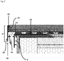
- the box-shaped channel can be covered with a fleece-like protective filter.
- a fleece-like protective filter which may for example consist of glass-fiber-like fleece with very low density, clogging of the box-shaped channel is particularly safe and effective avoided. It is preferred that the fleece-like protective filter is placed as the upper end of the box-shaped channel and is jammed by laying on the mounting leg of the end profile or by jamming with the layer and / or plate of the masonry above.
- the nonwoven protective filter has a sufficiently high rigidity so as not to self-assemble the box-shaped groove. It may also be preferred for some applications that the nonwoven protective filter be attached to a plate and / or a layer of the masonry which is located above the box-shaped channel. Depending on the application of the end profile, it is possible to use one, two or more fleece-like protective filters which are preferably arranged one above the other, with air layers preferably being present between the individual protective filter layers. It was completely surprising that through the providence of the fleece-like protective filter In particular, penetration of building chemicals or adhesive residues in the box-shaped channel can be particularly effectively avoided.
- the mounting leg has on its lower side mounting grooves, wherein the mounting grooves are configured semicircular. It is preferred for the purposes of the invention that the underside of the mounting leg rests on the masonry to be protected or is arranged between two layers of masonry to be protected.
- the attachment leg in its lower region preferably has 10-15 mounting grooves, each having a semicircle profile in the side view and are arranged with the flat side on the underside of the mounting leg.
- the fastening grooves are made of the same material as the other elements of the drainage profile. It is further preferred that the fastening grooves are arranged at regular intervals, that is to say equidistant from each other, on the underside of the fastening leg.
- the fixing grooves ensure a particularly stable and irreversible fixation of the fixing leg in the adhesive of the layer structure of the masonry to be protected and in particular prevent displacement of the profile particularly effective. It is preferred for the purposes of the invention that the attachment grooves have a height of preferably 0.2 to 2 mm, more preferably 0.6 to 1.4 mm, most preferably between 0.8 and 1.2 mm and most preferably at 1 mm.
- the fastening leg has adhesive grooves on its upper side.
- the provision of a plurality of adhesive grooves on the top of the attachment leg leads to an optimal adhesion of the tile adhesive and thus to a particularly stable attachment of the end profile according to the invention within the layer structure of the masonry to be protected.
- the wall area on a guideline for receiving holes for mounting a gully is preferred.
- the guideline serves to accommodate holes for holes in order to be able to fasten an additional gully to the end profile according to the invention.
- said gully is not part of the invention.
- the viewing area and the wall area are designed in a size ratio in the range of 1: 1 relative to one another.
- the viewing area and the wall area of the end profile serve to cover and / or cover all possible unevenness of the masonry to be protected, so that an aesthetically and qualitatively high-quality impression is created by the configuration of the end profile.
- the viewing area has a rounded drip edge.
- drip edge in the context of the invention, the portion of the lower portion of the field of view of the end profile is preferably referred to, which extends below the transverse portion.
- This area of the field of vision avoids a turbulence of the ventilation flows in the case of wind and, surprisingly, ensures particularly good and damage-free drainage of the masonry, which is to be protected by the end profile.
- water and / or raindrops located on the drip edge are not pressed against the house wall and / or façade in strong winds.
- the distance between the front edge of the viewing region and the front edge of the wall region is in the range of preferably 5 to 20 mm, more preferably 10 to 13 mm, most preferably 11 to 12 mm and most preferably 11, 5 mm.
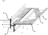
- FIG. 1 shows a lateral plan view of a preferred embodiment of a closure profile according to the invention with a viewing area (4) and a parallel thereto wall portion (5), which are interconnected by a perpendicular to the two areas (4, 5) extending transverse section (1).
- the viewing area (4), wall area (5) and the transverse section (1) form a box-shaped channel (16), which in particular allows the ventilation of the masonry to be protected by the end profile.
- the bottom of the box-shaped groove (16) is formed by the transverse section (1) having slot-like openings (2). Through these openings (2) any moisture or moisture can be effectively dissipated. Above all, the openings (2) but serve for intensive ventilation of the masonry in which a gas exchange through the openings (2) can take place.
- the box-shaped channel (16) can be protected against contamination by, for example, construction chemicals and / or adhesives with one or more fleece-like protective filters (10).
- the fleece-like protective filter (10) for example, be present directly above the box-shaped channel (16) and mounted on the mounting leg (23). It is also preferred for some applications if further fleece-like protective filters (10) are provided above another layer and / or plate of the masonry.
- the non-woven protective filter (10) may be either levitating or attached to an upper layer and / or slab of the masonry.
- FIG. 1 further shows the mounting leg (23), with which the end profile is anchored in the masonry.
- the fastening leg (23) is arranged between different layers, layers and / or plates of the masonry and engages, for example, in an adhesive and / or grout, wherein the adhesive and / or grout in the context of the invention as " Construction chemistry "is called.
- the mounting leg (23) has at least one opening (11), which may for example be designed triangular and large area, so that the adhesive and / or grout in this breakthrough (11) penetrate and thus a particularly stable attachment of the mounting leg (23). is possible.
- the attachment leg (23) further perforations (12), which may for example act as a further anchoring or mounting hole.
- fine adhesive grooves (15) are provided, which allow optimal adhesion of the tile adhesive on the top (22) of the mounting leg (23), since the surface (22) of the mounting leg (23 ) advantageously increase significantly.
- mounting grooves (7) are provided, which are designed semicircular and allow improved fixation of the mounting leg (23) in the adhesive.
- a vertical spacer web (6b) is provided, which forms a deformation space (14) together with the fastening leg (23) and the wall region (5).
- the deformation space (14) serves to accommodate possible clamping forces that may arise, for example, by horizontal and / or vertical movements within the masonry and the end profile.
- the deformation space (14) thus represents an essential element for the stabilization of the final profile and for stress relief within the masonry.
- the wall region (5) of the end profile furthermore has a horizontal spacer web (6a) which runs essentially perpendicular to the wall region (5) and acts as a spacer between the facade or the masonry and the wall region (5).
- the wall region (5) is supported by the horizontal spacer web (6a) on the wall, so that between wall and wall region (5) creates a cavity which serves to vent the masonry.
- gases that may be caused by the salt efflorescence of, for example, calcium chloride can be safely led away from the masonry.
- the viewing area (4) in an upper portion (19) and a lower portion (20) is divided.
- the transition between the areas (19, 20) is formed by a compensation groove (3), which is designed v-shaped.
- the V-shaped compensation groove (3) serves to accommodate vertical and / or horizontal movements of the masonry to be protected or individual layers and / or components of the masonry, at this predetermined breaking point of the upper portion (19) of the field of view (4) forward or can bend back to meet the particular possible horizontal movements. It may also be preferred for other applications, if not only the upper part (19) of the viewing area (4) kinks, but the entire viewing area (4) tilts forward or backward. This tilting movements are advantageously made possible in particular by the elastic material of the final profile.
- the preferred embodiment shown in FIG. 1 has anchoring ribs (8) on the rear side (18) of the upper area (19) of the viewing area (4), which are not arranged perpendicular to the viewing area (4), but with the viewing area (4). include an angle alpha that is less than 90 °. Due to the inclination of the anchoring ribs (8) with respect to the viewing area (4) a particularly resilient engagement of the anchoring ribs (8) in the grout and / or masonry is possible.
- the lower region (19) of the viewing area (4) has two anchoring ribs (8); However, it may also be preferred for other applications that the viewing area (4) has only one or more than two anchoring ribs (8).
Landscapes
- Engineering & Computer Science (AREA)
- Architecture (AREA)
- Civil Engineering (AREA)
- Structural Engineering (AREA)
- Finishing Walls (AREA)
Priority Applications (2)
| Application Number | Priority Date | Filing Date | Title |
|---|---|---|---|
| PL15196174T PL3173544T3 (pl) | 2015-11-25 | 2015-11-25 | Profil zamykający dla tarasu i balkonu |
| EP15196174.5A EP3173544B1 (de) | 2015-11-25 | 2015-11-25 | Abschlussprofil für terrasse und balkon |
Applications Claiming Priority (1)
| Application Number | Priority Date | Filing Date | Title |
|---|---|---|---|
| EP15196174.5A EP3173544B1 (de) | 2015-11-25 | 2015-11-25 | Abschlussprofil für terrasse und balkon |
Publications (2)
| Publication Number | Publication Date |
|---|---|
| EP3173544A1 EP3173544A1 (de) | 2017-05-31 |
| EP3173544B1 true EP3173544B1 (de) | 2019-02-20 |
Family
ID=54707561
Family Applications (1)
| Application Number | Title | Priority Date | Filing Date |
|---|---|---|---|
| EP15196174.5A Active EP3173544B1 (de) | 2015-11-25 | 2015-11-25 | Abschlussprofil für terrasse und balkon |
Country Status (2)
| Country | Link |
|---|---|
| EP (1) | EP3173544B1 (pl) |
| PL (1) | PL3173544T3 (pl) |
Families Citing this family (3)
| Publication number | Priority date | Publication date | Assignee | Title |
|---|---|---|---|---|
| DE202020100628U1 (de) * | 2020-02-05 | 2020-03-06 | Markus Riedl | Traufblech zum Ableiten von Regenwasser an einer Traufe |
| EP3875701A1 (de) * | 2020-03-04 | 2021-09-08 | Daw Se | Flüssigkeitsdurchlässiges gewirk-, gewebe-, gestrick- und/oder vliesbehältnis, flüssigkeitsdurchlässiges filterbehältnis und flüssigkeitsdurchlässiges filterbehältnis-modul und deren verwendung sowie gebäudewand, dachrinne, dachrinnenfallrohr und gebäudeabtropfkante |
| IT202100016958A1 (it) * | 2021-06-29 | 2022-12-29 | Progress Profiles Spa | Profilo perfezionato per terrazze e balconi |
Family Cites Families (4)
| Publication number | Priority date | Publication date | Assignee | Title |
|---|---|---|---|---|
| GB983080A (en) * | 1962-10-31 | 1965-02-10 | James Booth Aluminium Ltd | Improvements in roofing edge strips |
| DE19821785C2 (de) * | 1997-06-10 | 2000-07-06 | Baumjohann Adolf | Mehrteiliger Traufrandabschluß eines flach geneigten Terrassendaches |
| DE502004011159D1 (de) * | 2004-09-14 | 2010-06-24 | Richard Malcher | Balkonabschlussprofil |
| DE102013102587A1 (de) * | 2013-03-14 | 2014-09-18 | Sandro Thronicke | Abschlussprofil für Balkone und/oder Terrassen |
-
2015
- 2015-11-25 EP EP15196174.5A patent/EP3173544B1/de active Active
- 2015-11-25 PL PL15196174T patent/PL3173544T3/pl unknown
Non-Patent Citations (1)
| Title |
|---|
| None * |
Also Published As
| Publication number | Publication date |
|---|---|
| PL3173544T3 (pl) | 2019-08-30 |
| EP3173544A1 (de) | 2017-05-31 |
Similar Documents
| Publication | Publication Date | Title |
|---|---|---|
| DE69832105T3 (de) | Wand einer Gebäudefassade | |
| DE2310333A1 (de) | Wandanordnung bestehend aus einem inneren wandteil und einem aeusseren wandteil, die mit abstand voneinander angeordnet sind | |
| EP3173544B1 (de) | Abschlussprofil für terrasse und balkon | |
| AT511073B1 (de) | Fassadenkonstruktion zur Wärmedämmung und Verkleidung von Gebäudeaußenwänden sowie Verfahren zur Herstellung einer solchen Fassadenkonstruktion | |
| EP3245344B1 (de) | Pfosten-riegel-konstruktion | |
| EP3477012A1 (de) | Haltevorrichtung zur befestigung einer brüstungs- oder geländerplatte | |
| EP2024585B1 (de) | Holzboden | |
| WO2011063938A2 (de) | Wärmedämmsystem für eine gebäudehülle | |
| DE202016106511U1 (de) | Vorrichtung zur Befestigung von Fassadenelementen | |
| EP2937492B1 (de) | Konsolanker | |
| EP2522928B1 (de) | Vorrichtung für die Montage von Aufbauten auf einer flachen Ebene oder einer Ebene mit geringer Neigung | |
| DE102009036811B4 (de) | Dämmelement | |
| DE202005001609U1 (de) | Höhenverstellbare Entwässerungsrinne/-ablaufschächte für den Einbau vor Tür-/Fensterelementen, entlang von Gebäudefassaden oder in die Plattenbelagsflächen etc. | |
| EP2647779B1 (de) | Haltewinkel für eine Fassadenunterkonstruktion | |
| DE102005005525A1 (de) | Fugendichtungselement und Halter für Fugendichtungselemente | |
| DE3837377C2 (de) | Flachdach-Dämmkeil | |
| DE202005007662U1 (de) | Höhenverstellbare Entwässerungsrinne -/einlaufschächte für den Einbau vor Tür-/Fensterelementen, entlang von Gebäuden | |
| DE102007017612A1 (de) | Zarge für einen Balkon oder eine Terrasse sowie Verfahren zu deren Herstellung | |
| EP0201757A3 (de) | Fassadenbekleidung, insbesondere zur Sanierung von Altbauten | |
| DE102004026651B4 (de) | Mehrschichtiges Entkopplungs-, Abdichtungs- und Drainagesystem | |
| DE202005002356U1 (de) | Hinterlüftete wärmegedämmte Gebäudefassade | |
| DE202021103740U1 (de) | Vormontiertes isoliertes Fensterbanksystem | |
| DE3448392C2 (de) | Keramische Fassadenplatte | |
| AT516336B1 (de) | Profilverbindung | |
| WO2013186350A1 (de) | Dichtsystem zwischen einem fensterrahmen und einer wand eines gebäudes |
Legal Events
| Date | Code | Title | Description |
|---|---|---|---|
| PUAI | Public reference made under article 153(3) epc to a published international application that has entered the european phase |
Free format text: ORIGINAL CODE: 0009012 |
|
| STAA | Information on the status of an ep patent application or granted ep patent |
Free format text: STATUS: THE APPLICATION HAS BEEN PUBLISHED |
|
| AK | Designated contracting states |
Kind code of ref document: A1 Designated state(s): AL AT BE BG CH CY CZ DE DK EE ES FI FR GB GR HR HU IE IS IT LI LT LU LV MC MK MT NL NO PL PT RO RS SE SI SK SM TR |
|
| AX | Request for extension of the european patent |
Extension state: BA ME |
|
| STAA | Information on the status of an ep patent application or granted ep patent |
Free format text: STATUS: REQUEST FOR EXAMINATION WAS MADE |
|
| 17P | Request for examination filed |
Effective date: 20171130 |
|
| RBV | Designated contracting states (corrected) |
Designated state(s): AL AT BE BG CH CY CZ DE DK EE ES FI FR GB GR HR HU IE IS IT LI LT LU LV MC MK MT NL NO PL PT RO RS SE SI SK SM TR |
|
| GRAP | Despatch of communication of intention to grant a patent |
Free format text: ORIGINAL CODE: EPIDOSNIGR1 |
|
| STAA | Information on the status of an ep patent application or granted ep patent |
Free format text: STATUS: GRANT OF PATENT IS INTENDED |
|
| INTG | Intention to grant announced |
Effective date: 20180430 |
|
| GRAS | Grant fee paid |
Free format text: ORIGINAL CODE: EPIDOSNIGR3 |
|
| GRAA | (expected) grant |
Free format text: ORIGINAL CODE: 0009210 |
|
| STAA | Information on the status of an ep patent application or granted ep patent |
Free format text: STATUS: THE PATENT HAS BEEN GRANTED |
|
| AK | Designated contracting states |
Kind code of ref document: B1 Designated state(s): AL AT BE BG CH CY CZ DE DK EE ES FI FR GB GR HR HU IE IS IT LI LT LU LV MC MK MT NL NO PL PT RO RS SE SI SK SM TR |
|
| REG | Reference to a national code |
Ref country code: GB Ref legal event code: FG4D Free format text: NOT ENGLISH |
|
| REG | Reference to a national code |
Ref country code: CH Ref legal event code: EP |
|
| REG | Reference to a national code |
Ref country code: DE Ref legal event code: R096 Ref document number: 502015008001 Country of ref document: DE |
|
| REG | Reference to a national code |
Ref country code: AT Ref legal event code: REF Ref document number: 1098370 Country of ref document: AT Kind code of ref document: T Effective date: 20190315 |
|
| REG | Reference to a national code |
Ref country code: IE Ref legal event code: FG4D Free format text: LANGUAGE OF EP DOCUMENT: GERMAN |
|
| REG | Reference to a national code |
Ref country code: NL Ref legal event code: MP Effective date: 20190220 |
|
| REG | Reference to a national code |
Ref country code: LT Ref legal event code: MG4D |
|
| PG25 | Lapsed in a contracting state [announced via postgrant information from national office to epo] |
Ref country code: FI Free format text: LAPSE BECAUSE OF FAILURE TO SUBMIT A TRANSLATION OF THE DESCRIPTION OR TO PAY THE FEE WITHIN THE PRESCRIBED TIME-LIMIT Effective date: 20190220 Ref country code: NL Free format text: LAPSE BECAUSE OF FAILURE TO SUBMIT A TRANSLATION OF THE DESCRIPTION OR TO PAY THE FEE WITHIN THE PRESCRIBED TIME-LIMIT Effective date: 20190220 Ref country code: SE Free format text: LAPSE BECAUSE OF FAILURE TO SUBMIT A TRANSLATION OF THE DESCRIPTION OR TO PAY THE FEE WITHIN THE PRESCRIBED TIME-LIMIT Effective date: 20190220 Ref country code: LT Free format text: LAPSE BECAUSE OF FAILURE TO SUBMIT A TRANSLATION OF THE DESCRIPTION OR TO PAY THE FEE WITHIN THE PRESCRIBED TIME-LIMIT Effective date: 20190220 Ref country code: ES Free format text: LAPSE BECAUSE OF FAILURE TO SUBMIT A TRANSLATION OF THE DESCRIPTION OR TO PAY THE FEE WITHIN THE PRESCRIBED TIME-LIMIT Effective date: 20190220 Ref country code: PT Free format text: LAPSE BECAUSE OF FAILURE TO SUBMIT A TRANSLATION OF THE DESCRIPTION OR TO PAY THE FEE WITHIN THE PRESCRIBED TIME-LIMIT Effective date: 20190620 Ref country code: NO Free format text: LAPSE BECAUSE OF FAILURE TO SUBMIT A TRANSLATION OF THE DESCRIPTION OR TO PAY THE FEE WITHIN THE PRESCRIBED TIME-LIMIT Effective date: 20190520 |
|
| REG | Reference to a national code |
Ref country code: SK Ref legal event code: T3 Ref document number: E 31000 Country of ref document: SK |
|
| PG25 | Lapsed in a contracting state [announced via postgrant information from national office to epo] |
Ref country code: HR Free format text: LAPSE BECAUSE OF FAILURE TO SUBMIT A TRANSLATION OF THE DESCRIPTION OR TO PAY THE FEE WITHIN THE PRESCRIBED TIME-LIMIT Effective date: 20190220 Ref country code: RS Free format text: LAPSE BECAUSE OF FAILURE TO SUBMIT A TRANSLATION OF THE DESCRIPTION OR TO PAY THE FEE WITHIN THE PRESCRIBED TIME-LIMIT Effective date: 20190220 Ref country code: LV Free format text: LAPSE BECAUSE OF FAILURE TO SUBMIT A TRANSLATION OF THE DESCRIPTION OR TO PAY THE FEE WITHIN THE PRESCRIBED TIME-LIMIT Effective date: 20190220 Ref country code: GR Free format text: LAPSE BECAUSE OF FAILURE TO SUBMIT A TRANSLATION OF THE DESCRIPTION OR TO PAY THE FEE WITHIN THE PRESCRIBED TIME-LIMIT Effective date: 20190521 Ref country code: IS Free format text: LAPSE BECAUSE OF FAILURE TO SUBMIT A TRANSLATION OF THE DESCRIPTION OR TO PAY THE FEE WITHIN THE PRESCRIBED TIME-LIMIT Effective date: 20190620 Ref country code: BG Free format text: LAPSE BECAUSE OF FAILURE TO SUBMIT A TRANSLATION OF THE DESCRIPTION OR TO PAY THE FEE WITHIN THE PRESCRIBED TIME-LIMIT Effective date: 20190520 |
|
| PG25 | Lapsed in a contracting state [announced via postgrant information from national office to epo] |
Ref country code: EE Free format text: LAPSE BECAUSE OF FAILURE TO SUBMIT A TRANSLATION OF THE DESCRIPTION OR TO PAY THE FEE WITHIN THE PRESCRIBED TIME-LIMIT Effective date: 20190220 Ref country code: RO Free format text: LAPSE BECAUSE OF FAILURE TO SUBMIT A TRANSLATION OF THE DESCRIPTION OR TO PAY THE FEE WITHIN THE PRESCRIBED TIME-LIMIT Effective date: 20190220 Ref country code: IT Free format text: LAPSE BECAUSE OF FAILURE TO SUBMIT A TRANSLATION OF THE DESCRIPTION OR TO PAY THE FEE WITHIN THE PRESCRIBED TIME-LIMIT Effective date: 20190220 Ref country code: DK Free format text: LAPSE BECAUSE OF FAILURE TO SUBMIT A TRANSLATION OF THE DESCRIPTION OR TO PAY THE FEE WITHIN THE PRESCRIBED TIME-LIMIT Effective date: 20190220 Ref country code: AL Free format text: LAPSE BECAUSE OF FAILURE TO SUBMIT A TRANSLATION OF THE DESCRIPTION OR TO PAY THE FEE WITHIN THE PRESCRIBED TIME-LIMIT Effective date: 20190220 |
|
| REG | Reference to a national code |
Ref country code: DE Ref legal event code: R097 Ref document number: 502015008001 Country of ref document: DE |
|
| PG25 | Lapsed in a contracting state [announced via postgrant information from national office to epo] |
Ref country code: SM Free format text: LAPSE BECAUSE OF FAILURE TO SUBMIT A TRANSLATION OF THE DESCRIPTION OR TO PAY THE FEE WITHIN THE PRESCRIBED TIME-LIMIT Effective date: 20190220 |
|
| PLBE | No opposition filed within time limit |
Free format text: ORIGINAL CODE: 0009261 |
|
| STAA | Information on the status of an ep patent application or granted ep patent |
Free format text: STATUS: NO OPPOSITION FILED WITHIN TIME LIMIT |
|
| 26N | No opposition filed |
Effective date: 20191121 |
|
| PGFP | Annual fee paid to national office [announced via postgrant information from national office to epo] |
Ref country code: SK Payment date: 20191125 Year of fee payment: 5 |
|
| PG25 | Lapsed in a contracting state [announced via postgrant information from national office to epo] |
Ref country code: SI Free format text: LAPSE BECAUSE OF FAILURE TO SUBMIT A TRANSLATION OF THE DESCRIPTION OR TO PAY THE FEE WITHIN THE PRESCRIBED TIME-LIMIT Effective date: 20190220 |
|
| PG25 | Lapsed in a contracting state [announced via postgrant information from national office to epo] |
Ref country code: TR Free format text: LAPSE BECAUSE OF FAILURE TO SUBMIT A TRANSLATION OF THE DESCRIPTION OR TO PAY THE FEE WITHIN THE PRESCRIBED TIME-LIMIT Effective date: 20190220 |
|
| REG | Reference to a national code |
Ref country code: CH Ref legal event code: PL |
|
| PG25 | Lapsed in a contracting state [announced via postgrant information from national office to epo] |
Ref country code: MC Free format text: LAPSE BECAUSE OF FAILURE TO SUBMIT A TRANSLATION OF THE DESCRIPTION OR TO PAY THE FEE WITHIN THE PRESCRIBED TIME-LIMIT Effective date: 20190220 Ref country code: LU Free format text: LAPSE BECAUSE OF NON-PAYMENT OF DUE FEES Effective date: 20191125 Ref country code: CH Free format text: LAPSE BECAUSE OF NON-PAYMENT OF DUE FEES Effective date: 20191130 Ref country code: LI Free format text: LAPSE BECAUSE OF NON-PAYMENT OF DUE FEES Effective date: 20191130 |
|
| REG | Reference to a national code |
Ref country code: BE Ref legal event code: MM Effective date: 20191130 |
|
| GBPC | Gb: european patent ceased through non-payment of renewal fee |
Effective date: 20191125 |
|
| PG25 | Lapsed in a contracting state [announced via postgrant information from national office to epo] |
Ref country code: IE Free format text: LAPSE BECAUSE OF NON-PAYMENT OF DUE FEES Effective date: 20191125 Ref country code: GB Free format text: LAPSE BECAUSE OF NON-PAYMENT OF DUE FEES Effective date: 20191125 Ref country code: FR Free format text: LAPSE BECAUSE OF NON-PAYMENT OF DUE FEES Effective date: 20191130 |
|
| PG25 | Lapsed in a contracting state [announced via postgrant information from national office to epo] |
Ref country code: BE Free format text: LAPSE BECAUSE OF NON-PAYMENT OF DUE FEES Effective date: 20191130 |
|
| PG25 | Lapsed in a contracting state [announced via postgrant information from national office to epo] |
Ref country code: CY Free format text: LAPSE BECAUSE OF FAILURE TO SUBMIT A TRANSLATION OF THE DESCRIPTION OR TO PAY THE FEE WITHIN THE PRESCRIBED TIME-LIMIT Effective date: 20190220 |
|
| REG | Reference to a national code |
Ref country code: SK Ref legal event code: MM4A Ref document number: E 31000 Country of ref document: SK Effective date: 20201125 |
|
| PG25 | Lapsed in a contracting state [announced via postgrant information from national office to epo] |
Ref country code: MT Free format text: LAPSE BECAUSE OF FAILURE TO SUBMIT A TRANSLATION OF THE DESCRIPTION OR TO PAY THE FEE WITHIN THE PRESCRIBED TIME-LIMIT Effective date: 20190220 Ref country code: HU Free format text: LAPSE BECAUSE OF FAILURE TO SUBMIT A TRANSLATION OF THE DESCRIPTION OR TO PAY THE FEE WITHIN THE PRESCRIBED TIME-LIMIT; INVALID AB INITIO Effective date: 20151125 Ref country code: SK Free format text: LAPSE BECAUSE OF NON-PAYMENT OF DUE FEES Effective date: 20201125 |
|
| REG | Reference to a national code |
Ref country code: AT Ref legal event code: MM01 Ref document number: 1098370 Country of ref document: AT Kind code of ref document: T Effective date: 20201125 |
|
| PG25 | Lapsed in a contracting state [announced via postgrant information from national office to epo] |
Ref country code: AT Free format text: LAPSE BECAUSE OF NON-PAYMENT OF DUE FEES Effective date: 20201125 |
|
| PG25 | Lapsed in a contracting state [announced via postgrant information from national office to epo] |
Ref country code: MK Free format text: LAPSE BECAUSE OF FAILURE TO SUBMIT A TRANSLATION OF THE DESCRIPTION OR TO PAY THE FEE WITHIN THE PRESCRIBED TIME-LIMIT Effective date: 20190220 |
|
| PGFP | Annual fee paid to national office [announced via postgrant information from national office to epo] |
Ref country code: CZ Payment date: 20231116 Year of fee payment: 9 |
|
| PGFP | Annual fee paid to national office [announced via postgrant information from national office to epo] |
Ref country code: PL Payment date: 20231113 Year of fee payment: 9 |
|
| PGFP | Annual fee paid to national office [announced via postgrant information from national office to epo] |
Ref country code: DE Payment date: 20241129 Year of fee payment: 10 |
|
| PG25 | Lapsed in a contracting state [announced via postgrant information from national office to epo] |
Ref country code: CZ Free format text: LAPSE BECAUSE OF NON-PAYMENT OF DUE FEES Effective date: 20241125 |