EP3171104A1 - Verfahren zum bodengefrieren - Google Patents
Verfahren zum bodengefrieren Download PDFInfo
- Publication number
- EP3171104A1 EP3171104A1 EP15003267.0A EP15003267A EP3171104A1 EP 3171104 A1 EP3171104 A1 EP 3171104A1 EP 15003267 A EP15003267 A EP 15003267A EP 3171104 A1 EP3171104 A1 EP 3171104A1
- Authority
- EP
- European Patent Office
- Prior art keywords
- freezing
- tube
- hollow body
- contact medium
- freezing tube
- Prior art date
- Legal status (The legal status is an assumption and is not a legal conclusion. Google has not performed a legal analysis and makes no representation as to the accuracy of the status listed.)
- Granted
Links
Images


Classifications
-
- E—FIXED CONSTRUCTIONS
- E02—HYDRAULIC ENGINEERING; FOUNDATIONS; SOIL SHIFTING
- E02D—FOUNDATIONS; EXCAVATIONS; EMBANKMENTS; UNDERGROUND OR UNDERWATER STRUCTURES
- E02D3/00—Improving or preserving soil or rock, e.g. preserving permafrost soil
- E02D3/11—Improving or preserving soil or rock, e.g. preserving permafrost soil by thermal, electrical or electro-chemical means
- E02D3/115—Improving or preserving soil or rock, e.g. preserving permafrost soil by thermal, electrical or electro-chemical means by freezing
-
- E—FIXED CONSTRUCTIONS
- E02—HYDRAULIC ENGINEERING; FOUNDATIONS; SOIL SHIFTING
- E02D—FOUNDATIONS; EXCAVATIONS; EMBANKMENTS; UNDERGROUND OR UNDERWATER STRUCTURES
- E02D3/00—Improving or preserving soil or rock, e.g. preserving permafrost soil
- E02D3/11—Improving or preserving soil or rock, e.g. preserving permafrost soil by thermal, electrical or electro-chemical means
-
- F—MECHANICAL ENGINEERING; LIGHTING; HEATING; WEAPONS; BLASTING
- F25—REFRIGERATION OR COOLING; COMBINED HEATING AND REFRIGERATION SYSTEMS; HEAT PUMP SYSTEMS; MANUFACTURE OR STORAGE OF ICE; LIQUEFACTION SOLIDIFICATION OF GASES
- F25D—REFRIGERATORS; COLD ROOMS; ICE-BOXES; COOLING OR FREEZING APPARATUS NOT OTHERWISE PROVIDED FOR
- F25D3/00—Devices using other cold materials; Devices using cold-storage bodies
- F25D3/10—Devices using other cold materials; Devices using cold-storage bodies using liquefied gases, e.g. liquid air
-
- F—MECHANICAL ENGINEERING; LIGHTING; HEATING; WEAPONS; BLASTING
- F25—REFRIGERATION OR COOLING; COMBINED HEATING AND REFRIGERATION SYSTEMS; HEAT PUMP SYSTEMS; MANUFACTURE OR STORAGE OF ICE; LIQUEFACTION SOLIDIFICATION OF GASES
- F25D—REFRIGERATORS; COLD ROOMS; ICE-BOXES; COOLING OR FREEZING APPARATUS NOT OTHERWISE PROVIDED FOR
- F25D17/00—Arrangements for circulating cooling fluids; Arrangements for circulating gas, e.g. air, within refrigerated spaces
- F25D17/02—Arrangements for circulating cooling fluids; Arrangements for circulating gas, e.g. air, within refrigerated spaces for circulating liquids, e.g. brine
-
- F—MECHANICAL ENGINEERING; LIGHTING; HEATING; WEAPONS; BLASTING
- F25—REFRIGERATION OR COOLING; COMBINED HEATING AND REFRIGERATION SYSTEMS; HEAT PUMP SYSTEMS; MANUFACTURE OR STORAGE OF ICE; LIQUEFACTION SOLIDIFICATION OF GASES
- F25D—REFRIGERATORS; COLD ROOMS; ICE-BOXES; COOLING OR FREEZING APPARATUS NOT OTHERWISE PROVIDED FOR
- F25D7/00—Devices using evaporation effects without recovery of the vapour
Definitions
- the invention relates to a device for freezing soil with a freezing tube, which is closed at one end face, and an inner tube projecting into the freezing tube for supplying a refrigerant. Further, the invention relates to a method for freezing soil with a freezing tube and an inner tube projecting into the freezing tube, wherein a refrigerant is passed through the inner tube into the freezing tube.
- the freezing tubes After icing the freezing tubes usually remain in the ground. In some cases, however, this hinders further construction progress, since, for example, full-cutting machines are not able to pass through the steel or copper pipes used as freezing pipes. In these cases, it is therefore necessary to pull the freezing tubes out of the ground after icing.
- the pulling of the freezing tubes presents a problem for several reasons. After completion of the icing of the surrounding soil is still frozen for weeks.
- the tensile force that can be placed on the freezing tubes is limited by the material and also a negative pressure is generated when pulling the freezing tube on the underside, which exerts a train of the opposing force on the freezing tube.
- Object of the present invention is therefore to provide a device for floor freezing and a corresponding method, which allow easier removal of the freezing pipes from the ground.
- a device for freezing soil with a freezing tube wherein the freezing tube is closed at one end face, and which has an inner tube projecting into the freezing tube for supplying a refrigerant, and which is characterized in that a hollow body is provided, whose inner diameter is larger than the outer diameter of the freezing tube.
- the inventive method for freezing soil with a freezing tube and an inner tube projecting into the freezing tube, wherein a refrigerant is passed through the inner tube in the freezing tube, is characterized in that a hollow body whose inner diameter is greater than the outer diameter of the freezing tube, in the soil is introduced and the freezing tube is introduced into the hollow body.
- the removal of the freezing tube from the ground is facilitated by providing a hollow body around the freezing tube.
- the freezer tube thus does not come into direct contact with the ground and thus does not freeze directly to the ground.
- hollow body should in particular comprise elongated hollow bodies, such as a tube or a hose.
- the hollow body may be made of a flexible or inflexible material.
- the hollow body has a circular cross-section. But it can also have a rectangular, oval or other cross-section.
- the hollow body remains after removal of the freezing tube in the ground. It is therefore advantageous to manufacture the hollow body in such a way that it does not damage it in contact with soil working machines. This can be done, for example, that the hollow body is made correspondingly thin and the wall thickness of the hollow body is a maximum of 6mm, preferably 1 to 2 mm.
- the hollow body can be made of a polymer or plastic material, which does not oppose a tillage machine such a resistance that the machine is damaged.
- the hollow body is preferably made at least partially or completely from a polymer material.
- polytetrafluoroethylene PTFE
- PTFE polytetrafluoroethylene
- Polytetrafluoroethylene (PTFE) has the advantage that it has a very low coefficient of friction, so that the extraction of the freezing tube is facilitated by the low friction between the freezing tube and cladding tube.
- polymer materials or plastic materials for example perfluoroalkoxy copolymer, polyethylene, polyamide, polyoxymethylene, ethylene / vinyl acetate, polyetherimide or melamine / phenolic resin or other phenolic resins, as well as epoxy resins.
- composite materials which contain polymer materials can also be used.
- the hollow body can also be made of two or more over- and / or juxtaposed materials. For example, it is possible to connect a hollow body made of a first plastic or of metal with a second plastic.
- the freezing tube with its cylindrical or lateral surface no longer comes into direct contact with the surrounding soil and can therefore be removed more easily from the ground.
- the extraction or pulling of the freezing tube is further facilitated by the fact that the hollow body is closed in a preferred embodiment on one of its end faces, on the front side, which is introduced into the ground. In this way, a freezing of the end face of the freezing tube is prevented on the ground.
- a contact medium is located between the freezing tube and the hollow body.
- the contact medium may serve to increase the heat conduction from the freezer tube via the hollow body to the surrounding soil. If appropriate, the contact medium can also compensate for different thermal expansion coefficients and thus a different length contraction of the freezing tube and the hollow body during cooling of the freezing tube.
- the freezing tube and / or hollow body can also be produced Have tolerances, so that the heat conduction contact between the freezing tube and the hollow body is not optimal in all places. This too can be improved by the contact medium.
- the contact medium is advantageously chosen so that one or more of the above advantages are achieved.
- the contact medium used is advantageously a substance which has a freezing point of less than 0 ° C or at most 0 ° C. At temperatures greater than 0 ° C, the contact medium is liquid or gaseous.
- the contact medium When cooling the freezing tubes, which preferably takes place by means of liquid nitrogen or an aqueous salt solution (brine), of course, the contact medium is cooled. Depending on how much is cooled and what freezing point the contact medium has, the contact medium can also go into the solid phase. This may in turn mean that the freezing tube is frozen to the hollow body.
- aqueous salt solution aqueous salt solution
- the contact medium Before the planned removal of the freezing tube from the hollow body, the contact medium is heated and in particular so far that it passes into the liquid or gaseous state. The freezing tube is then surrounded by a liquid or gaseous substance and can be pulled out of the hollow body relatively easily.
- a contact medium is preferably selected which has a freezing point below 0 ° C.
- the contact medium therefore passes into the liquid state earlier than the water frozen in the surrounding soil to ice.
- the soil can be left in the frozen state while the contact medium is already liquid.
- any type of liquid or gas can be used. Preference is given to substances with a low freezing point and harmless water hazard class.
- Examples of such contact media are aqueous alcohol solutions with ethanol and propanol or aqueous salt solutions such as sodium chloride, calcium chloride or magnesium chloride.
- the heating of the contact medium takes place, for example, with an electric heater.
- an electrical heater such as an electric heating wire, a heating coil, a heating tape or a heating jacket, is provided so that when heated current flows through the heater, the contact medium is heated.
- a heating wire may be wrapped around the freezing tube prior to introduction of the freezing tube into the hollow body.
- the heating wire is spirally wound around the freezer tube. It has also proven to be beneficial to lay the heating wire or generally the heating element axially along the freezing tube. In this case, it is also possible to provide a plurality of heating elements connected in series or in parallel.
- the electric heater can be inserted or otherwise introduced after the introduction of the freezing tube into the hollow body, but before the supply of the contact medium in the space between the freezing tube and the hollow body.
- the electric heater may also be possible to apply the electric heater only after the introduction of the contact medium.
- the heating is provided before the cooling of the freezing tube and the freezing of the soil.
- a heating wire and the freezer tube itself can be used as a resistance heater.
- a power source is connected directly to the freezer tube, so that the freezer tube is traversed by a stream and heats up.
- a heat transfer line for supplying a heat carrier.
- a heat transfer line for example a hose or a tube, is provided so that it runs at least in sections through the intermediate space between the freezing tube and the hollow body.
- the heat carrier line can be inserted from above into the gap or through a hole or similar opening in the shell or the end face of the hollow body. In the latter case, part of the heat carrier line outside the hollow body would pass through the ground. If space permits, it is also possible to provide the heat carrier line wholly or partly inside the freezer tube.
- a gas or a liquid having a temperature above the freezing point of the contact medium is supplied via the heat carrier line as a heat transfer medium.
- the temperature is the heat carrier between -30 ° C and +450 ° C, especially when a gaseous heat transfer medium is used.
- the heat carrier is a liquid, then its temperature is preferably between 0 ° C and 150 ° C, more preferably 50 ° C to 150 ° C.
- the heat transfer medium comes into thermal contact with the contact medium and at least heats the contact medium to such an extent that it changes into the liquid state of aggregation.
- the means for heating the contact medium for example an electric heater or a heat carrier line, are preferably at least partially wound around the freezer tube.
- the means for heating the contact medium are preferably arranged helically around the freezing tube or in one or more axial paths along the freezing tube. The freezing tube is then inserted together with the means for heating the contact medium in the hollow body.
- the heat carrier line has a predetermined breaking point and / or outlet openings for the heat carrier. A part of the heat carrier can then escape via the outlet openings and come into direct contact with the contact medium. The heat transfer to the contact medium can be further intensified.
- the heat carrier line may have a predetermined breaking point which breaks at a certain pressure (for example 4 bar). By breaking the predetermined breaking point, the hot or hot heat carrier can escape and circulate around the freezing tube and / or the hollow body, whereby the melting of the contact medium is accelerated.
- other hoses or tubes may be placed on e.g. half the length are attached, which allow the removal of already cooled heat transfer medium and thus increase the circulation over the entire length of the freezing tube. When the contact medium is liquid again, the freezer tube can be pulled out.
- the supply of the refrigerant medium for example, liquid nitrogen
- the liquid nitrogen heats and vaporizes.
- the resulting nitrogen gas can be withdrawn through the annular gap between the inner tube and the freezing tube upwards.
- an additional exhaust pipe in the freezing tube through which the gaseous nitrogen can escape or subtracted.
- the exhaust pipe has the advantage that in the freezing tube defined flow conditions can be established and that the gaseous nitrogen does not flow through the freezing pipe over its entire length, but at a defined predetermined height, namely the height of the inlet opening of the exhaust pipe is withdrawn.
- the uppermost part of the soil can be cooled less or, depending on the design, even frozen at all.
- the above statements also apply to other refrigerants than nitrogen.
- the invention allows in a simple way the removal, that is, the extraction, of the freezing tube. So that the soil can be frozen first with the help of the freezing tubes. Subsequently, the freezing pipes are removed and only the ducts remain in the ground.
- the length of the freezing tube is for example 1 to 50 m, often 10m to 30 m.
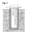
- the freezing tube 1 is closed at its lower end face 2.
- the upper end face 3 is also closed, but has two passages 4, 5 for an inner tube 6 and an exhaust pipe 7.
- the inner tube 6 is open at the lower end 8.
- a supply line not shown in the drawing, a nitrogen tank is connected to the inner tube 6.
- the hollow body 10 is made of polytetrafluoroethylene and has a wall thickness of 0.5 to 6 mm.
- the hollow body 10 is designed as a cladding tube and closed at its lower end face 12.
- a heat carrier line 11 is then inserted.
- the heat carrier line 11 can be designed either as a hose or as a flexible or inflexible pipe.
- the heat carrier line 11 is arranged so that it is as close as possible to the hollow body 10, so that sufficient space for the freezing tube remains.
- the heat carrier line 11 extends both along the jacket of the hollow body 10 and along its bottom or end face 12.
- a supply for a hot or hot fluid in particular air or an aqueous salt solution, connected.
- the freezing tube is inserted into the hollow body 10, so that the heat carrier line 11 comes to rest in the intermediate space 13 between the freezing tube 1 and the hollow body 10.
- the gap 13 is finally filled with a liquid contact medium 14, for example with an aqueous salt solution or water.
- liquid nitrogen is supplied via the inner tube 6 and passed into the interior of the freezing tube 1.
- the liquid nitrogen cools the ground 9 via the surrounding contact medium 14.
- the nitrogen evaporates.
- the vaporized, cold gaseous nitrogen which is also referred to as exhaust gas, draws more heat from the ground.
- a non-illustrated solenoid valve is controlled. In this way a steady flow of nitrogen with optimum efficiency is ensured.
- a frozen area forms around the freezing tube 1.
- the freezing tubes 1 from the To remove soil as this could hinder the further construction progress.
- full-cutting machines may not be able to pass through the steel or copper pipes used as freezing tubes 1.
- the freezing tubes 1 are pulled out of the ground 9 or out of the hollow body 10 in such a case.
- a gaseous heat transfer medium is passed through the heat carrier line 11.
- a heat transfer medium with a temperature between, for example, -50 ° C and 0 ° C can be used.
- a heat carrier having a higher temperature of, for example, 50 ° C to 200 ° C, e.g. heated air or heated nitrogen gas used to effect a faster melting and heating of the contact medium.
- the heat transfer medium flows through the heat carrier line 11 and thereby heats the surrounding contact medium 14. If the contact medium 14 was in the solid state of aggregation, it is liquefied again. Otherwise, at least the viscosity of the contact medium 14 is reduced by the heating, so that the contact medium 14 is flowable and the freezing tube 1 is easier to move in the contact medium 14.
- the freezing tube 1 is pulled out of the hollow body 10 with a pulling device, not shown in the drawing.
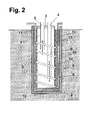
- FIG. 2 an alternative embodiment of the invention is shown.
- This version is different from the one below FIG. 1 in that the heat carrier line 11 is wound around the freezing tube 1.
- the heat carrier line 11 is placed helically around the freezing tube 1.
- This has the advantage that the freezer tube 1 can be easily inserted into the hollow body 10 together with the heat carrier line 11.
- a uniform heating of the contact medium 14 is achieved by the winding of the heat carrier line 11 to the freezing tube 1.
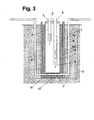
- FIG. 3 shows an embodiment of the invention, in which the heat carrier line 11 extends partially through the ground 9.
- a borehole 15 is first drilled, which has a larger diameter than the hollow body 10.
- the heat carrier line 11 is guided through the wall of the hollow body 10, extends along the lower end face 12 of the hollow body and is led out again on the opposite side of the hollow body 10.
- the hollow body 10 is introduced into the borehole 15 together with the heat carrier line 11. As described above, the freezing pipe 1 and the contact medium 14 are then placed in the hollow body 1.
- the heat carrier line 11 is guided outside the hollow body 10 upwards and the remaining wellbore 15 is backfilled with soil or aqueous or pasty building materials, such as cement suspension, bentonite or twilight.
- the heat carrier line 11 may further be provided with a predetermined breaking point 16 in the section in which it runs within the hollow body 10.
- the predetermined breaking point 16 is designed so that it bursts when a certain pressure, for example 3 bar, is exceeded and releases an opening.
- the heat transfer medium then flows through this opening into the interior of the hollow body 10, thereby accelerating the melting and heating of the contact medium 14.
- the execution according to FIG. 4 is essentially a combination of Figures 2 and 3 , however, instead of the predetermined breaking point 16, a plurality of holes or perforations 17 are provided in the section of the heat carrier line 11 in which it extends within the hollow body 10.
- the holes or perforations 17 have, for example, a diameter between 0.05 mm and 0.4 mm, for example 0.15 mm or 0.2 mm, so that a part of the heat carrier can flow through these holes 17 into the interior of the hollow body 10.
- an electric heater 18 for heating the contact medium 14 is provided instead of a heat carrier line, an electric heater 18 for heating the contact medium 14.
- a heating wire 18 is placed helically around the freezing tube 1 and pushed with the freezing tube 1 in the hollow body 10.
- the intermediate space 13 between the freezing tube 1 and the hollow body 10 is filled with the contact medium 14.
- the freezing tube 1 is then cooled as described above with liquid nitrogen and the surrounding soil is frozen.
- a heating current is passed through the heating wire 18.
- electric heater can be used not only as an alternative to a heat carrier line, but also supplementary. In the latter case, the heating of the contact medium 14 is significantly accelerated by the heat transfer from the heat carrier and by the electric heater.
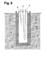
- FIG. 6 to see another variant of the invention.
- the heating of the contact medium 14 by supplying a heat transfer medium into the freezing tube 1.
- a heat transfer medium in particular a hot gas, for example, gaseous nitrogen at a temperature of 50 to 450 ° C is passed into the freezing tube 1.
- the contact medium 14 is in direct contact with the outside of the freezing tube 1 and is heated by the heat carrier.
- the heat carrier can be supplied for example via the inner tube 6 and withdrawn via the exhaust pipe 7 again, so that a circulation of the heat carrier is generated.
- the circulation of the heat carrier can be further improved when the upper end face 3 of the freezing tube 1 is opened.
Landscapes
- Engineering & Computer Science (AREA)
- Structural Engineering (AREA)
- Life Sciences & Earth Sciences (AREA)
- General Engineering & Computer Science (AREA)
- Paleontology (AREA)
- Soil Sciences (AREA)
- General Life Sciences & Earth Sciences (AREA)
- Mining & Mineral Resources (AREA)
- Environmental & Geological Engineering (AREA)
- Civil Engineering (AREA)
- Agronomy & Crop Science (AREA)
- Chemical & Material Sciences (AREA)
- Combustion & Propulsion (AREA)
- Physics & Mathematics (AREA)
- Mechanical Engineering (AREA)
- Thermal Sciences (AREA)
- Investigation Of Foundation Soil And Reinforcement Of Foundation Soil By Compacting Or Drainage (AREA)
- Excavating Of Shafts Or Tunnels (AREA)
Abstract
Description
- Die Erfindung betrifft eine Vorrichtung zum Gefrieren von Erdboden mit einem Gefrierrohr, welches an einer Stirnseite geschlossen ist, und einem in das Gefrierrohr ragenden Innenrohr zur Zuführung eines Kältemittels. Ferner bezieht sich die Erfindung auf ein Verfahren zum Gefrieren von Erdboden mit einem Gefrierrohr und einem in das Gefrierrohr ragenden Innenrohr, wobei ein Kältemittel über das Innenrohr in das Gefrierrohr geleitet wird.
- Im Tief- und Grundbau müssen häufig Maßnahmen zum Abdichten oder Abstützen des Erdbodens getroffen werden. Bei temporären Aufgaben bietet sich der Einsatz eines künstlichen Bodengefrierens mit flüssigem Stickstoff als Kälteträger an.
- Beim Bodengefrieren erfolgt der Kälteeintrag über ein Gefrierrohr mit Doppelrohrsystem. Flüssiger Stickstoff gelangt durch ein Innenrohr nach unten in das Gefrierrohr, verdampft und gibt beim Aufsteigen im Ringraum seine Kälteenergie an das umliegende Erdreich. ab. Durch den Wärmeentzug wird das Wasser im umliegenden Erdreich abgekühlt und gefroren.
- Nach erfolgter Vereisung verbleiben die Gefrierrohre in der Regel im Erdreich. In manchen Fällen ist dies jedoch für den weiteren Baufortschritt hinderlich, da beispielsweise Vollschnittmaschinen nicht in der Lage sind die als Gefrierrohre eingesetzten Stahl- oder Kupferrohre zu durchfahren. In diesen Fällen ist es daher nötig, die Gefrierrohre nach der Vereisung aus dem Erdreich zu ziehen.
- Das Ziehen der Gefrierrohre stellt sich jedoch aus mehreren Gründen problematisch dar. Nach Beendigung der Vereisung ist der umgebende Erdboden noch wochenlang gefroren. Die Zugkraft, die auf die Gefrierrohre gegeben werden kann, ist materialbedingt begrenzt und außerdem wird beim Ziehen des Gefrierrohres an dessen Unterseite ein Unterdruck erzeugt, das eine dem Zug entgegengerichtete Kraft auf das Gefrierrohr ausübt.
- Aufgabe vorliegender Erfindung ist es daher, eine Vorrichtung zum Bodengefrieren und ein entsprechendes Verfahren aufzuzeigen, welche ein einfacheres Entfernen der Gefrierrohre aus dem Erdboden erlauben.
- Diese Aufgabe wird durch Vorrichtung zum Gefrieren von Erdboden mit einem Gefrierrohr gelöst, wobei das Gefrierrohr an einer Stirnseite geschlossen ist, und welche ein in das Gefrierrohr ragendes Innenrohr zur Zuführung eines Kältemittels, aufweist, und welches dadurch gekennzeichnet ist, dass ein Hohlkörper vorgesehen ist, dessen Innendurchmesser größer als der Außendurchmesser des Gefrierrohres ist.
- Das erfindungsgemäße Verfahren zum Gefrieren von Erdboden mit einem Gefrierrohr und einem in das Gefrierrohr ragenden Innenrohr, wobei ein Kältemittel über das Innenrohr in das Gefrierrohr geleitet wird, zeichnet sich dadurch aus, dass ein Hohlkörper, dessen Innendurchmesser größer als der Außendurchmesser des Gefrierrohres ist, in den Erdboden eingebracht wird und das Gefrierrohr in der Hohlkörper eingebracht wird.
- Erfindungsgemäß wird das Entfernen des Gefrierrohres aus dem Erdreich dadurch erleichtert, dass ein Hohlkörper um das Gefrierrohr vorgesehen wird. Das Gefrierrohr kommt somit nicht in direkten Kontakt mit dem Erdboden und friert somit nicht direkt am Erdboden fest.
- Der Begriff Hohlkörper soll insbesondere längliche Hohlkörper, wie ein Rohr oder einen Schlauch, umfassen. Der Hohlkörper kann aus einem flexiblen oder unflexiblen Material gefertigt sein. In der Regel besitzt der Hohlkörper einen kreisrunden Querschnitt. Er kann aber auch einen rechteckigen, ovalen oder anderen Querschnitt aufweisen.
- Der Hohlkörper verbleibt nach dem Entfernen des Gefrierrohres im Erdboden. Es ist daher vorteilhaft, den Hohlkörper so zu fertigen, dass dieser bei Kontakt mit Bodenbearbeitungsmaschinen diese nicht beschädigt. Dies kann beispielsweise dadurch geschehen, dass der Hohlkörper entsprechend dünn ausgeführt wird und die Wandstärke des Hohlkörpers maximal 6mm, vorzugsweise 1 bis 2 mm beträgt. Alternativ oder auch ergänzend kann der Hohlkörper aus einem Polymer- oder Kunststoffmaterial gefertigt werden, welches einer Bodenbearbeitungsmaschine keinen solchen Widerstand entgegensetzt, dass die Maschine beschädigt wird.
- Der Hohlkörper ist vorzugsweise zumindest teilweise oder auch vollständig aus einem Polymerwerkstoff gefertigt. Hierbei hat sich Polytetrafluorethylen (PTFE) bewährt. Polytetrafluorethylen (PTFE) hat den Vorteil, dass es einen sehr niedrigen Reibungskoeffizienten besitzt, so dass das Herausziehen des Gefrierrohres durch die geringe Reibung zwischen Gefrierrohr und Hüllrohr erleichtert wird.
- Es ist aber auch möglich andere Polymerwerkstoffe oder Kunststoffmaterialien, beispielsweise Perfluoralkoxy-Copolymer, Polyethylen, Polyamid, Polyoxymethylen, Ethylen/Vinylacetat, Polyetherimid oder Melamin/Phenolharz oder andere Phenolharze wie auch Epoxydharze, zu verwenden. Insbesondere können auch Verbundwerkstoffe, welche Polymermaterialien enthalten, eingesetzt werden. Der Hohlkörper kann auch aus zwei oder mehr über- und/oder nebeneinander angeordneten Werkstoffen gefertigt sein. Beispielsweise ist es möglich, einen Hohlkörper aus einem ersten Kunststoff oder aus Metall mit einem zweiten Kunststoff zu verbinden.
- Durch den erfindungsgemäßen Einsatz des Hohlkörpers kommt das Gefrierrohr mit seiner Zylinder- oder Mantelfläche nicht mehr mit dem umgebenden Erdboden in direkten Kontakt und kann daher leichter aus dem Erdboden entfernt werden. Das Herausziehen oder Ziehen des Gefrierrohres wird weiterhin dadurch erleichtert, dass der Hohlkörper in einer bevorzugten Ausführungsform an einer seiner Stirnseiten, und zwar an der Stirnseite, die in den Erdboden eingebracht wird, geschlossen ist. Auf diese Weise wird auch ein Anfrieren der Stirnfläche des Gefrierrohres am Erdboden verhindert.
- In einer weiteren Ausführungsform befindet sich zwischen dem Gefrierrohr und dem Hohlkörper ein Kontaktmedium. Das Kontaktmedium kann dazu dienen, die Wärmeleitung vom Gefrierrohr über den Hohlkörper auf den umgebenden Erdboden zu erhöhen. Das Kontaktmedium kann gegebenenfalls auch unterschiedliche thermische Ausdehnungskoeffizienten und damit eine unterschiedliche Längenkontraktion von Gefrierrohr und Hohlkörper beim Abkühlen des Gefrierrohres kompensieren. Schließlich können Gefrierrohr und/oder Hohlkörper auch herstellungsbedingte Toleranzen aufweisen, so dass der Wärmeleitungskontakt zwischen Gefrierrohr und Hohlkörper nicht an allen Stellen optimal ist. Auch dies kann durch das Kontaktmedium verbessert werden. Das Kontaktmedium wird von Vorteil so gewählt, dass ein oder mehrere der oben genannten Vorteile erzielt werden.
- Als Kontaktmedium wird von Vorteil ein Stoff verwendet, welcher einen Gefrierpunkt von weniger als 0°C oder höchstens 0° C besitzt. Bei Temperaturen von mehr als 0°C ist das Kontaktmedium flüssig oder gasförmig.
- Beim Abkühlen der Gefrierrohre, was vorzugsweise mittels flüssigem Stickstoff oder einer wässrigen Salzlösung (Sole) erfolgt, wird selbstverständlich auch das Kontaktmedium abgekühlt. Je nachdem, wie stark abgekühlt wird und welchen Gefrierpunkt das Kontaktmedium besitzt, kann das Kontaktmedium auch in die feste Phase übergehen. Dies kann wiederum bedeuten, dass das Gefrierrohr an dem Hohlkörper festgefriert.
- Es hat sich daher als günstig erwiesen, Mittel zur Erwärmung des Kontaktmediums vorzusehen. Vor der geplanten Entfernung des Gefrierrohres aus dem Hohlkörper wird das Kontaktmedium erwärmt und zwar insbesondere soweit, dass es in den flüssigen oder gasförmigen Zustand übergeht. Das Gefrierrohr wird dann von einem flüssigen oder gasförmigen Stoff umgeben und kann relativ einfach aus dem Hohlkörper gezogen werden.
- Wie oben bereits ausgeführt, wird vorzugsweise ein Kontaktmedium gewählt, welches einen Gefrierpunkt unterhalb von 0°C besitzt. Das Kontaktmedium geht daher früher in den flüssigen Zustand über als das im umgebenden Erdboden zu Eis gefrorene Wasser. Der Erdboden kann im gefrorenen Zustand belassen werden, während das Kontaktmedium bereits flüssig ist.
- Als Kontaktmedium kann jegliche Art von Flüssigkeit oder Gas verwendet werden. Bevorzugt werden Stoffe mit einem niedrigen Gefrierpunkt und unbedenklicher Wassergefährdungsklasse. Beispiele für solche Kontaktmedien sind wässrige Alkohollösungen mit Ethanol und Propanol oder wässerige Salzlösungen wie Natriumchlorid, Calciumchlorid oder Magnesiumchlorid.
- Die Erwärmung des Kontaktmediums erfolgt zum Beispiel mit einer elektrischen Heizung. Hierzu wird eine elektrische Heizung, beispielsweise ein elektrischer Heizdraht, eine Heizwendel, ein Heizband oder eine Heizmanschette, so vorgesehen, dass bei Stromfluss durch die Heizung das Kontaktmedium erwärmt wird. Zum Beispiel kann ein Heizdraht vor dem Einbringen des Gefrierrohres in den Hohlkörper um das Gefrierrohr gewickelt werden. Der Heizdraht wird beispielsweise spiralförmig um das Gefrierrohr gelegt. Es hat sich auch als günstig erwiesen, den Heizdraht oder allgemein das Heizelement axial entlang des Gefrierrohres zu verlegen. Hierbei können auch mehrere seriell oder parallel geschaltete Heizelemente vorgesehen sein.
- Die elektrische Heizung kann auch nach dem Einbringen des Gefrierrohres in den Hohlkörper, aber vor dem Zuführen des Kontaktmediums, in den Zwischenraum zwischen Gefrierrohr und Hohlkörper eingelegt oder anderweitig eingebracht werden. Schließlich kann es je nach Wahl des Kontaktmediums auch möglich sein, die elektrische Heizung erst nach dem Einbringen des Kontaktmediums anzubringen. In der Regel wird die Heizung aber vor dem Abkühlen des Gefrierrohres und dem Gefrieren des Erdbodens vorgesehen. Anstelle eines Heizdrahts kann auch das Gefrierrohr selbst als Widerstandsheizung verwendet werden. In diesem Fall wird eine Stromquelle direkt an das Gefrierrohr angeschlossen, so dass das Gefrierrohr von einem Strom durchflossen wird und sich erwärmt.
- Anstelle oder zusätzlich zu einer elektrischen Heizung kann auch eine Wärmeträgerleitung zur Zuführung eines Wärmeträgers vorgesehen sein. Hierzu wird eine Wärmeträgerleitung, beispielsweise ein Schlauch oder ein Rohr, so vorgesehen, dass sie zumindest abschnittsweise durch den Zwischenraum zwischen Gefrierrohr und Hohlkörper verläuft. Die Wärmeträgerleitung kann von oben in den Zwischenraum oder auch durch eine Bohrung oder ähnliche Öffnung im Mantel oder der Stirnfläche des Hohlkörpers eingeführt werden. Im letzteren Fall würde ein Teil der Wärmeträgerleitung außerhalb des Hohlkörpers durch den Erdboden verlaufen. Wenn es die Platzverhältnisse erlauben, ist es auch möglich, die Wärmeträgerleitung ganz oder teilweise im Inneren des Gefrierrohres vorzusehen.
- Zum Erwärmen des Kontaktmediums wird über die Wärmeträgerleitung als Wärmeträger ein Gas oder eine Flüssigkeit mit einer Temperatur oberhalb des Gefrierpunktes des Kontaktmediums zugeführt. Vorzugsweise beträgt die Temperatur des Wärmeträgers zwischen -30 °C und +450 °C, insbesondere wenn ein gasförmiger Wärmeträger eingesetzt wird. Ist der Wärmeträger eine Flüssigkeit, so beträgt dessen Temperatur vorzugsweise zwischen 0 °C und 150 °C, besonders bevorzugt 50°C bis 150 °C. Der Wärmeträger kommt mit dem Kontaktmedium in thermischen Kontakt und wärmt das Kontaktmedium zumindest soweit an, dass es in den flüssigen Aggregatszustand übergeht.
- Die Mittel zur Erwärmung des Kontaktmediums, zum Beispiel eine elektrische Heizung oder eine Wärmeträgerleitung, werden vorzugsweise zumindest zum Teil um das Gefrierrohr gewickelt. Die Mittel zur Erwärmung des Kontaktmediums werden hierbei bevorzugt schraubenförmig um das Gefrierrohr oder auch in einer oder mehreren axialen Bahnen entlang des Gefrierrohres angeordnet. Das Gefrierrohr wird anschließend gemeinsam mit den Mitteln zur Erwärmung des Kontaktmediums in den Hohlkörper eingeschoben.
- In einer anderen Ausführungsform besitzt die Wärmeträgerleitung eine Sollbruchstelle und/oder Austrittsöffnungen für den Wärmeträger. Über die Austrittsöffnungen kann dann ein Teil des Wärmeträgers austreten und in direkten Kontakt mit dem Kontaktmedium gelangen. Die Wärmeübertragung auf das Kontaktmedium kann so weiter intensiviert werden. Alternativ oder ergänzend kann die Wärmeträgerleitung eine Sollbruchstelle aufweisen, die bei einem bestimmten Druck bricht (z.B. 4 bar). Durch das Brechen der Sollbruchstelle kann der warme oder heiße Wärmeträger austreten und um das Gefrierrohr und /oder den Hohlkörper zirkulieren, wodurch das Schmelzen des Kontaktmediums beschleunigt wird. Zusätzlich können weitere Schläuche oder Rohre auf z.B. halber Länge angebracht werden, die die Abfuhr von bereits abgekühltem Wärmeträger ermöglichen und damit die Zirkulation über die gesamte Länge des Gefrierrohres vergrößern. Wenn das Kontaktmedium wieder flüssig ist, kann das Gefrierrohr herausgezogen werden.
- Die Zufuhr des Kältemediums, beispielsweise von flüssigem Stickstoff, in das Gefrierrohr erfolgt über das Innenrohr. Beim Abkühlen des Gefrierrohres und des Erdbodens erwärmt sich der flüssige Stickstoff und verdampft. Das entstehende Stickstoffgas kann über den Ringspalt zwischen dem Innenrohr und dem Gefrierrohr nach oben abgezogen werden. Es kann aber auch ein zusätzliches Abgasrohr in dem Gefrierrohr vorgesehen sein, über welches der gasförmige Stickstoff entweichen kann oder abgezogen wird. Das Abgasrohr hat den Vorteil, dass im Gefrierrohr definierte Strömungsverhältnisse hergestellt werden können und dass der gasförmige Stickstoff das Gefrierrohr nicht über dessen gesamte Länge durchströmt, sondern auf einer definierten vorgegebenen Höhe, nämlich der Höhe der Eintrittsöffnung des Abgasrohres, abgezogen wird. So kann beispielsweise der oberste Teil des Erdbodens weniger stark gekühlt oder je nach Ausführung sogar überhaupt nicht gefroren werden. Die obigen Ausführungen gelten selbstverständlich auch für andere Kältemittel als Stickstoff.
- Die Erfindung erlaubt auf einfache Weise die Entfernung, das heißt das Herausziehen, des Gefrierrohres. Damit kann der Erdboden zunächst mit Hilfe der Gefrierrohre gefroren werden. Anschließend werden die Gefrierrohre entfernt und nur die Hüllrohre verbleiben im Erdboden.
- Die Erfindung sowie weitere Einzelheiten der Erfindung werden im Folgenden anhand von in den Zeichnungen schematisch dargestellten Ausführungsbeispielen näher erläutert. Hierbei zeigen:
- Figur 1
- eine erste Ausführungsform einer erfindungsgemäßen Vorrichtung zum Bodengefrieren,
- Figur 2
- eine zweite Ausführungsform,
- Figur 3
- eine dritte Ausführungsform,
- Figur 4
- eine vierte Ausführungsform,
- Figur 5
- eine fünfte Ausführungsform und
- Figur 6
- eine sechste Ausführungsform der Erfindung.
- In allen Figuren sind gleiche Elemente mit den gleichen Bezugsziffern versehen.
- In
Figur 1 ist eine erste Ausführungsform der Erfindung schematisch dargestellt. Ein Gefrierrohr 1 aus einem gut wärmeleitenden Material, insbesondere aus Kupfer, besitzt einen Durchmesser von beispielsweise 50 bis 100 mm. Die Länge des Gefrierrohres beträgt beispielsweise 1 bis 50 m, häufig10m bis 30 m. - Das Gefrierrohr 1 ist an seiner unteren Stirnseite 2 geschlossen. Die obere Stirnfläche 3 ist ebenfalls verschlossen, weist aber zwei Durchgänge 4, 5 für ein Innenrohr 6 und ein Abgasrohr 7 auf. Das Innenrohr 6 ist am unteren Ende 8 offen. Über eine in der Zeichnung nicht dargestellte Versorgungsleitung ist ein Stickstofftank an das Innenrohr 6 angeschlossen.
- In den zu vereisenden Erdboden 9 wird ein Bohrloch gebohrt, in welches ein Hohlkörper 10 eingebracht wird. Der Hohlkörper 10 besteht aus Polytetrafluorethylen und weist eine Wandstärke von 0,5 bis 6 mm auf. Der Hohlkörper 10 ist als ein Hüllrohr ausgeführt und an seinem unteren, stirnseitigen Ende 12 geschlossen.
- In den Hohlkörper 10 wird dann eine Wärmeträgerleitung 11 eingelegt. Die Wärmeträgerleitung 11 kann entweder als Schlauch oder als flexibles oder unflexibles Rohr ausgeführt sein. Die Wärmeträgerleitung 11 wird so angeordnet, dass sie sich möglichst nahe am Hohlkörper 10 befindet, so dass ausreichend Platz für das Gefrierrohr verbleibt. Die Wärmeträgerleitung 11 verläuft sowohl entlang des Mantels des Hohlkörpers 10 als auch entlang dessen Boden bzw. Stirnfläche 12. An die Wärmeträgerleitung wird eine Zuführung für ein warmes oder heißes Fluid, insbesondere Luft oder eine wässrige Salzlösung, angeschlossen.
- Anschließend wird das Gefrierrohr in den Hohlkörper 10 eingeschoben, so dass die Wärmeträgerleitung 11 in dem Zwischenraum 13 zwischen dem Gefrierrohr 1 und dem Hohlkörper 10 zu liegen kommt.
- Der Zwischenraum 13 wird abschließend mit einem flüssigen Kontaktmedium 14, beispielsweise mit einer wässerigen Salzlösung oder Wasser, gefüllt.
- Zur Vereisung des Erdbodens 9 wird flüssiger Stickstoff über das Innenrohr 6 zugeführt und in das Innere des Gefrierrohres 1 geleitet. Der flüssige Stickstoff kühlt über das umgebende Kontaktmedium 14 den Erdboden 9 ab. Hierbei verdampft der Stickstoff. Der verdampfte, kalte gasförmige Stickstoff, der auch als Abgas bezeichnet wird, entzieht dem Boden weitere Wärme. Über die Temperatur des Abgases wird ein nicht dargestelltes Magnetventil gesteuert. Auf diese Weise wird ein stetiger Fluss an Stickstoff mit optimaler Effizienz sichergestellt.
- Nach einiger Zeit bildet sich ein gefrorener Bereich um das Gefrierrohr 1 aus. Nach erfolgter Vereisung ist es in manchen Fällen günstig, die Gefrierrohre 1 aus dem Erdboden zu entfernen, da diese den weiteren Baufortschritt behindern könnten. Beispielsweise können Vollschnittmaschinen nicht in der Lage sein, die als Gefrierrohre 1 eingesetzten Stahl- oder Kupferrohre zu durchfahren.
- Erfindungsgemäß werden in einem solchen Fall die Gefrierrohre 1 aus dem Erdboden 9 beziehungsweise aus dem Hohlkörper 10 herausgezogen. Hierzu wird zunächst ein gasförmiger Wärmeträger durch die Wärmeträgerleitung 11 geleitet. Wenn das Gefrierrohr zuvor mit flüssigem Stickstoff abgekühlt wurde, kann zunächst auch ein Wärmeträger mit einer Temperatur zwischen beispielsweise -50°C und 0°C verwendet werden. So kann man in dieser Phase zum Beispiel verdampften gasförmigen Stickstoff direkt aus einem Stickstofftank nehmen. In der Regel wird aber ein Wärmeträger mit einer höheren Temperatur von zum Beispiel 50°C bis 200 °C, z.B. erhitzte Luft oder erwärmtes Stickstoffgas, eingesetzt, um eine schnelleres Aufschmelzen und Erwärmen des Kontaktmediums zu bewirken.
- Der Wärmeträger strömt durch die Wärmeträgerleitung 11 und erwärmt dabei das umgebende Kontaktmedium 14. Sofern das Kontaktmedium 14 im festen Aggregatszustand war, wird es wieder verflüssigt. Ansonsten wird zumindest die Viskosität des Kontaktmediums 14 durch die Erwärmung verringert, so dass das Kontaktmedium 14 fließfähiger wird und sich das Gefrierrohr 1 leichter in dem Kontaktmedium 14 bewegen lässt.
- Wenn das Kontaktmedium 14 flüssig ist oder eine bestimmte Fließfähigkeit erreicht hat, wird das Gefrierrohr 1 mit einer in der Zeichnung nicht dargestellten Zugvorrichtung aus dem Hohlkörper 10 gezogen.
- In
Figur 2 ist eine alternative Ausführung der Erfindung gezeigt. Diese Ausführung unterscheidet sich von der nachFigur 1 darin, dass die Wärmeträgerleitung 11 um das Gefrierrohr 1 gewickelt ist. Die Wärmeträgerleitung 11 ist schraubenförmig um das Gefrierrohr 1 gelegt. Dies hat zum einen den Vorteil, dass das Gefrierrohr 1 gemeinsam mit der Wärmeträgerleitung 11 leicht in der Hohlkörper 10 eingeschoben werden kann. Zum anderen wird durch die Wicklung der Wärmeträgerleitung 11 um das Gefrierrohr 1 eine gleichmäßige Erwärmung des Kontaktmediums 14 erreicht.Figur 3 zeigt eine Ausführungsform der Erfindung, bei der die Wärmeträgerleitung 11 zum Teil durch den Erdboden 9 verläuft. Hierbei wird zunächst ein Bohrloch 15 gebohrt, welches einen größeren Durchmesser als der Hohlkörper 10 besitzt. Die Wärmeträgerleitung 11 wird durch die Wandung des Hohlkörpers 10 geführt, verläuft entlang der unteren Stirnfläche 12 des Hohlkörpers und wird auf der gegenüberliegenden Seite des Hohlkörpers 10 wieder herausgeführt. - Der Hohlkörper 10 wird gemeinsam mit der Wärmeträgerleitung 11 in das Bohrloch 15 eingebracht. Wie oben beschrieben werden dann das Gefrierrohr 1 und das Kontaktmedium 14 in dem Hohlkörper 1 platziert. Die Wärmeträgerleitung 11 wird außerhalb des Hohlkörpers 10 nach oben geführt und das verbleibende Bohrloch 15 wird wieder mit Erdreich oder wässrigen oder pastösen Baustoffen, beispielsweise Zementsuspension, Bentonit oder Dämmer, verfüllt. Die Wärmeträgerleitung 11 kann weiterhin in dem Abschnitt, in dem sie innerhalb des Hohlkörpers 10 verläuft, mit einer Sollbruchstelle 16 versehen sein. Die Sollbruchstelle 16 ist so ausgeführt, dass sie bei Überschreiten eines bestimmten Drucks, beispielsweise 3 bar, birst und eine Öffnung freigibt. Durch diese Öffnung strömt dann der Wärmeträger in das Innere des Hohlkörpers 10 und beschleunigt dadurch das Aufschmelzen und Erwärmen des Kontaktmediums 14.
- Die Ausführung gemäß
Figur 4 ist im Wesentlichen eine Kombination derFiguren 2 und3 . Jedoch sind anstelle der Sollbruchstelle 16 mehrere Löcher oder Perforationen 17 in dem Abschnitt der Wärmeträgerleitung 11, in dem sie innerhalb des Hohlkörpers 10 verläuft, vorgesehen. Die Löcher oder Perforationen 17 haben beispielsweise einen Durchmesser zwischen 0,05 mm und 0,4 mm, beispielsweise 0,15 mm oder 0,2 mm, so dass ein Teil des Wärmeträgers durch diese Löcher 17 in das Innere des Hohlkörpers 10 strömen kann. - Bei der Variante nach
Figur 5 ist anstelle einer Wärmeträgerleitung eine elektrische Heizung 18 zur Erwärmung des Kontaktmediums 14 vorgesehen. Ein Heizdraht 18 wird schraubenförmig um das Gefrierrohr 1 gelegt und mit dem Gefrierrohr 1 in der Hohlkörper 10 geschoben. Der Zwischenraum 13 zwischen dem Gefrierrohr 1 und dem Hohlkörper 10 wird mit dem Kontaktmedium 14 gefüllt. Das Gefrierrohr 1 wird dann, wie oben beschrieben, mit flüssigem Stickstoff abgekühlt und das umgebende Erdreich gefroren. Zum Auftauen und Erwärmen des Kontaktmediums 14 wird der Heizdraht 18 an eine Stromquelle 19 angeschlossen und ein Heizstrom wird durch den Heizdraht 18 geleitet. - Die in
Figur 5 gezeigte elektrische Heizung kann nicht nur als Alternative zu einer Wärmeträgerleitung eingesetzt werden, sondern auch ergänzend. Im letzteren Fall wird die Erwärmung des Kontaktmediums 14 durch den Wärmeübertrag von dem Wärmeträger und durch die elektrische Heizung deutlich beschleunigt. - Schließlich ist in
Figur 6 eine weitere Variante der Erfindung zu sehen. In diesem Fall erfolgt die Erwärmung des Kontaktmediums 14 durch Zuführung eines Wärmeträgers in das Gefrierrohr 1. Hierzu wird ein Wärmeträger, insbesondere ein warmes Gas, beispielsweise gasförmiger Stickstoff mit einer Temperatur von 50 bis 450° C in das Gefrierrohr 1 geleitet. Das Kontaktmedium 14 steht mit der Außenseite des Gefrierrohres 1 in direktem Kontakt und wird durch den Wärmeträger erwärmt. Der Wärmeträger kann beispielsweise über das Innenrohr 6 zugeführt und über das Abgasrohr 7 wieder abgezogen werden, so dass eine Zirkulation des Wärmeträgers erzeugt wird. Die Zirkulation des Wärmeträgers kann weiter verbessert werden, wenn die obere Stirnfläche 3 des Gefrierrohres 1 geöffnet wird. - Die Erwärmung des Kontaktmediums 14 über das Gefrierrohr 1, wie sie anhand von
Figur 6 erläutert wurde, kann selbstverständlich auch ergänzend zu den in denFiguren 1 bis 5 beschriebenen Verfahren eingesetzt werden. Das Kontaktmedium 14 kann durch eine oder mehrere der folgenden Methoden erwärmt werden: - Erwärmung durch einen in das Gefrierrohr eingebrachten Wärmeträger
- Erwärmung durch einen Wärmeträger, welcher durch eine mit dem Kontaktmedium in Wärmeaustauschkontakt stehende Wärmeträgerleitung strömt,
- Erwärmung durch einen Wärmeträger, welcher direkt in das Kontaktmedium geleitet wird und/oder
- Erwärmung mittels einer elektrischen Heizung.
Claims (14)
- Vorrichtung zum Gefrieren von Erdboden mit einem Gefrierrohr (1), welches an einer Stirnseite (2) geschlossen ist, und einem in das Gefrierrohr (1) ragenden Innenrohr (6) zur Zuführung eines Kältemittels, dadurch gekennzeichnet, dass ein Hohlkörper (10) vorgesehen ist, dessen Innendurchmesser größer als der Außendurchmesser des Gefrierrohres (1) ist.
- Vorrichtung nach Anspruch 1, dadurch gekennzeichnet, dass der Hohlkörper (10) einen Polymerwerkstoff, insbesondere Polytetrafluorethylen, umfasst.
- Vorrichtung nach Anspruch 1 oder 2, dadurch gekennzeichnet, dass der Hohlkörper (10) an einer seiner Stirnseiten (12) geschlossen ist.
- Vorrichtung nach einem der vorhergehenden Ansprüche, dadurch gekennzeichnet, dass sich zwischen dem Gefrierrohr (1) und dem Hohlkörper (10) ein Kontaktmedium (14) befindet, welches einen Gefrierpunkt von höchstens 0° C besitzt.
- Vorrichtung nach Anspruch 4, dadurch gekennzeichnet, dass Mittel (11, 18) zur Erwärmung des Kontaktmediums (14) vorgesehen sind.
- Vorrichtung nach Anspruch 5, dadurch gekennzeichnet, dass die Mittel (11, 18) zur Erwärmung des Kontaktmediums (14) eine elektrische Heizung (18) und/oder eine Wärmeträgerleitung (11) zur Zuführung eines Wärmeträgers umfassen.
- Vorrichtung nach einem der Ansprüche 5 oder 6, dadurch gekennzeichnet, dass zumindest ein Teil der Mittel (11, 18) zur Erwärmung des Kontaktmediums (14) um das Gefrierrohr (1) gewickelt sind.
- Vorrichtung nach einem der Ansprüche 6 oder 7, dadurch gekennzeichnet, dass die Mittel zur Erwärmung des Kontaktmediums (14) eine Wärmeträgerleitung (11) zur Zuführung eines Wärmeträgers umfassen und dass die Wärmeträgerleitung (11) eine Sollbruchstelle (16) und/oder Austrittsöffnungen (17) für den Wärmeträger aufweist.
- Vorrichtung nach einem der vorhergehenden Ansprüche, dadurch gekennzeichnet, dass ein in das Gefrierrohr (1) ragendes Abgasrohr (7) vorgesehen ist.
- Verfahren zum Gefrieren von Erdboden (9) mit einem Gefrierrohr (1) und einem in das Gefrierrohr (1) ragenden Innenrohr (6), wobei ein Kältemittel über das Innenrohr (6) in das Gefrierrohr (1) geleitet wird, dadurch gekennzeichnet, dass ein Hohlkörper (10), dessen Innendurchmesser größer als der Außendurchmesser des Gefrierrohres (1) ist, in den Erdboden (9) eingebracht wird und das Gefrierrohr (1) in den Hohlkörper (10) eingebracht wird.
- Verfahren nach Anspruch 10, dadurch gekennzeichnet, dass ein Kontaktmedium (14), welches einen Gefrierpunkt von höchstens 0° C besitzt, in den Zwischenraum (13) zwischen dem Hohlkörper (10) und dem Gefrierrohr (1) eingebracht wird.
- Verfahren nach einem der Ansprüche 10 oder 11, dadurch gekennzeichnet, dass das Gefrierrohr (1) nach dem Gefrieren des Erdbodens (9) aus dem Hohlkörper (10) entfernt wird.
- Verfahren nach Anspruch 12, dadurch gekennzeichnet, dass das Gefrierrohr (1) und/oder das Kontaktmedium (14) vor dem Entfernen des Gefrierrohres (1) erwärmt werden.
- Verfahren nach einem der Ansprüche 10 bis 13, dadurch gekennzeichnet, dass flüssiger Stickstoff oder eine wässrige Salzlösung als Kältemittel in das Gefrierrohr (1) geleitet wird.
Priority Applications (3)
| Application Number | Priority Date | Filing Date | Title |
|---|---|---|---|
| PL15003267T PL3171104T3 (pl) | 2015-11-17 | 2015-11-17 | Urządzenie i sposób zamrażania gruntu |
| EP15003267.0A EP3171104B1 (de) | 2015-11-17 | 2015-11-17 | Vorrichtung und verfahren zum bodengefrieren |
| US15/350,177 US10196792B2 (en) | 2015-11-17 | 2016-11-14 | Ground freezing method |
Applications Claiming Priority (1)
| Application Number | Priority Date | Filing Date | Title |
|---|---|---|---|
| EP15003267.0A EP3171104B1 (de) | 2015-11-17 | 2015-11-17 | Vorrichtung und verfahren zum bodengefrieren |
Publications (2)
| Publication Number | Publication Date |
|---|---|
| EP3171104A1 true EP3171104A1 (de) | 2017-05-24 |
| EP3171104B1 EP3171104B1 (de) | 2021-01-27 |
Family
ID=54601588
Family Applications (1)
| Application Number | Title | Priority Date | Filing Date |
|---|---|---|---|
| EP15003267.0A Active EP3171104B1 (de) | 2015-11-17 | 2015-11-17 | Vorrichtung und verfahren zum bodengefrieren |
Country Status (3)
| Country | Link |
|---|---|
| US (1) | US10196792B2 (de) |
| EP (1) | EP3171104B1 (de) |
| PL (1) | PL3171104T3 (de) |
Cited By (4)
| Publication number | Priority date | Publication date | Assignee | Title |
|---|---|---|---|---|
| CN108221950A (zh) * | 2018-02-02 | 2018-06-29 | 中国矿业大学 | 一种供液管开槽的液氮冻结器 |
| EP3441529A1 (de) * | 2017-08-10 | 2019-02-13 | Linde Aktiengesellschaft | Vorrichtung und verfahren zum gefrieren von erdreich |
| RU202182U1 (ru) * | 2020-11-18 | 2021-02-05 | Вадим Васильевич Пассек | Коаксиальная вставка для термоопоры |
| CN119332719A (zh) * | 2024-10-28 | 2025-01-21 | 中建三局第三建设工程有限责任公司 | 一种多年冻土中大直径螺旋叶片螺旋桩基础的施工方法 |
Families Citing this family (9)
| Publication number | Priority date | Publication date | Assignee | Title |
|---|---|---|---|---|
| JP6448085B2 (ja) * | 2014-12-19 | 2019-01-09 | ケミカルグラウト株式会社 | 地盤凍結工法及び地盤凍結システム |
| JP6687976B2 (ja) * | 2016-03-16 | 2020-04-28 | ケミカルグラウト株式会社 | 凍結工法 |
| JP6260977B1 (ja) * | 2016-10-26 | 2018-01-17 | 株式会社エコ・プランナー | 地中熱交換装置及び地中熱交換装置用の貯液槽の構築方法 |
| JP7197258B2 (ja) * | 2017-08-07 | 2022-12-27 | 清水建設株式会社 | 凍結工法 |
| JP6931618B2 (ja) * | 2018-01-29 | 2021-09-08 | 鹿島建設株式会社 | 流動抑制方法 |
| CN110512589B (zh) * | 2019-09-02 | 2021-06-29 | 南京林业大学 | 一种真空降排水联合氧化镁碳化的浅层超软地基固化方法 |
| JP7349297B2 (ja) * | 2019-09-05 | 2023-09-22 | 前田建設工業株式会社 | 止水装置、及び止水方法 |
| IT201900020338A1 (it) * | 2019-11-11 | 2021-05-11 | Gennaro Normino | Sistemi innovativi per l’utilizzo sostenibile di energia geotermica a bassa entalpia mediante il recupero di sonde di congelamento |
| CN112609670A (zh) * | 2020-12-08 | 2021-04-06 | 中交天津港湾工程研究院有限公司 | 一种塑料排水板及其端部接头构成的地基加热循环系统 |
Citations (5)
| Publication number | Priority date | Publication date | Assignee | Title |
|---|---|---|---|---|
| US4256188A (en) * | 1978-07-17 | 1981-03-17 | Resource Development Consultants Ltd. | Method and apparatus for drilling a hole in a body of ice and for the destruction of a body of ice |
| DE3036842A1 (de) * | 1980-09-30 | 1982-05-19 | Linde Ag, 6200 Wiesbaden | Verfahren zum bodengefrieren |
| DE102004058457A1 (de) * | 2004-12-03 | 2006-06-22 | Linde Ag | Verfahren zum Ziehen von Gefrierrohren |
| DE102006007980B3 (de) * | 2006-02-21 | 2007-08-02 | Messer Group Gmbh | Vorrichtung und Verfahren zum Bodengefrieren |
| CN201031387Y (zh) * | 2007-04-18 | 2008-03-05 | 上海地铁运营有限公司 | 液氮冻结器 |
Family Cites Families (6)
| Publication number | Priority date | Publication date | Assignee | Title |
|---|---|---|---|---|
| US5050386A (en) * | 1989-08-16 | 1991-09-24 | Rkk, Limited | Method and apparatus for containment of hazardous material migration in the earth |
| US5507149A (en) * | 1994-12-15 | 1996-04-16 | Dash; J. Gregory | Nonporous liquid impermeable cryogenic barrier |
| US5816314A (en) * | 1995-09-19 | 1998-10-06 | Wiggs; B. Ryland | Geothermal heat exchange unit |
| US5623986A (en) * | 1995-09-19 | 1997-04-29 | Wiggs; B. Ryland | Advanced in-ground/in-water heat exchange unit |
| MXPA04003716A (es) * | 2001-10-24 | 2005-04-08 | Shell Int Research | Mejoramiento del suelo contaminado con mercurio. |
| US9611608B2 (en) * | 2012-03-28 | 2017-04-04 | Daniel Mageau | Zone freeze pipe |
-
2015
- 2015-11-17 EP EP15003267.0A patent/EP3171104B1/de active Active
- 2015-11-17 PL PL15003267T patent/PL3171104T3/pl unknown
-
2016
- 2016-11-14 US US15/350,177 patent/US10196792B2/en active Active
Patent Citations (5)
| Publication number | Priority date | Publication date | Assignee | Title |
|---|---|---|---|---|
| US4256188A (en) * | 1978-07-17 | 1981-03-17 | Resource Development Consultants Ltd. | Method and apparatus for drilling a hole in a body of ice and for the destruction of a body of ice |
| DE3036842A1 (de) * | 1980-09-30 | 1982-05-19 | Linde Ag, 6200 Wiesbaden | Verfahren zum bodengefrieren |
| DE102004058457A1 (de) * | 2004-12-03 | 2006-06-22 | Linde Ag | Verfahren zum Ziehen von Gefrierrohren |
| DE102006007980B3 (de) * | 2006-02-21 | 2007-08-02 | Messer Group Gmbh | Vorrichtung und Verfahren zum Bodengefrieren |
| CN201031387Y (zh) * | 2007-04-18 | 2008-03-05 | 上海地铁运营有限公司 | 液氮冻结器 |
Cited By (6)
| Publication number | Priority date | Publication date | Assignee | Title |
|---|---|---|---|---|
| EP3441529A1 (de) * | 2017-08-10 | 2019-02-13 | Linde Aktiengesellschaft | Vorrichtung und verfahren zum gefrieren von erdreich |
| CN108221950A (zh) * | 2018-02-02 | 2018-06-29 | 中国矿业大学 | 一种供液管开槽的液氮冻结器 |
| CN108221950B (zh) * | 2018-02-02 | 2020-01-14 | 中国矿业大学 | 一种供液管开槽的液氮冻结器 |
| RU202182U1 (ru) * | 2020-11-18 | 2021-02-05 | Вадим Васильевич Пассек | Коаксиальная вставка для термоопоры |
| CN119332719A (zh) * | 2024-10-28 | 2025-01-21 | 中建三局第三建设工程有限责任公司 | 一种多年冻土中大直径螺旋叶片螺旋桩基础的施工方法 |
| CN119332719B (zh) * | 2024-10-28 | 2025-12-09 | 中建三局第三建设工程有限责任公司 | 一种多年冻土中大直径螺旋叶片螺旋桩基础的施工方法 |
Also Published As
| Publication number | Publication date |
|---|---|
| US10196792B2 (en) | 2019-02-05 |
| PL3171104T3 (pl) | 2021-06-14 |
| US20170138010A1 (en) | 2017-05-18 |
| EP3171104B1 (de) | 2021-01-27 |
Similar Documents
| Publication | Publication Date | Title |
|---|---|---|
| EP3171104B1 (de) | Vorrichtung und verfahren zum bodengefrieren | |
| DE69117395T2 (de) | Verfahren und Einrichtung zum elektrischen Erwärmen von Rohrleitungen | |
| EP2507474B1 (de) | Vorrichtung und verfahren zur gewinnung, insbesondere in-situ-gewinnung, einer kohlenstoffhaltigen substanz aus einer unterirdischen lagerstätte | |
| EP3240945B1 (de) | Druckluftspeicherkraftwerk sowie verfahren zum betreiben eines druckluftspeicherkraftwerks | |
| EP3063335B1 (de) | Verfahren zur erzeugung eines zusammenhängenden eiskörpers bei einer bodenvereisung | |
| DE102013114578A1 (de) | Glühofen und Verfahren zum Glühen eines Strangs aus Stahl | |
| EP4127550B1 (de) | Vorrichtung zum aushärten einer rohrleitungsauskleidung | |
| WO2011101052A2 (de) | Vorrichtung und verfahren zur gewinnung, insbesondere in-situ-gewinnung, einer kohlenstoffhaltigen substanz aus einer unterirdischen lagerstätte | |
| EP3056847B1 (de) | Vorrichtung und Verfahren zur Temperierung eines Körpers | |
| EP2309008A2 (de) | Vorrichtung zum Herstellen gehärteter Stahlbauteile | |
| EP4174426B1 (de) | Vorrichtung zum kühlen von flüssigkeiten | |
| WO2021198472A1 (de) | Vorrichtung zum einziehen, und insbesondere aushärten, einer rohrleitungsauskleidung | |
| WO2011101228A2 (de) | Vorrichtung und verfahren zur gewinnung, insbesondere in-situ-gewinnung, einer kohlenstoffhaltigen substanz aus einer unterirdischen lagerstätte | |
| EP2920537B1 (de) | Verfahren zum herstellen eines für ein vorbestimmtes medium druckdichten hohlkörpers | |
| DE3535622A1 (de) | Verfahren und vorrichtung zum zeitweiligen verschliessen von grossrohrleitungen | |
| DE102021125688A1 (de) | Wärmetauscher und Verfahren zum Betanken eines Fahrzeuges | |
| DE19930504A1 (de) | Verfahren zum Auffahren von Strecken in stark wasserführenden Schichten und dafür geeignete Bohreinrichtung | |
| DE2614221C2 (de) | Vorrichtung zur Bodenvereisung für unterirdische Bauwerke, Baugruben od. dgl. | |
| DE19720428A1 (de) | Nebelkartusche | |
| DE1778319A1 (de) | Automatische Vorrichtung zur Herstellung ausgedehnter Schlaeuche | |
| DE102008027182B3 (de) | Vorrichtung zum peripheren Einfrieren des Inhalts von flüssigkeitsführenden Rohrleitungen | |
| DE102012111136A1 (de) | Verfahren zum Herstellen eines für ein vorbestimmtes Medium druckdichten Hohlkörpers | |
| DE3026644C2 (de) | ||
| HK1237856B (en) | Device and method for ground freezing | |
| EP3945268A1 (de) | Wärmepumpsystem |
Legal Events
| Date | Code | Title | Description |
|---|---|---|---|
| PUAI | Public reference made under article 153(3) epc to a published international application that has entered the european phase |
Free format text: ORIGINAL CODE: 0009012 |
|
| STAA | Information on the status of an ep patent application or granted ep patent |
Free format text: STATUS: THE APPLICATION HAS BEEN PUBLISHED |
|
| AK | Designated contracting states |
Kind code of ref document: A1 Designated state(s): AL AT BE BG CH CY CZ DE DK EE ES FI FR GB GR HR HU IE IS IT LI LT LU LV MC MK MT NL NO PL PT RO RS SE SI SK SM TR |
|
| AX | Request for extension of the european patent |
Extension state: BA ME |
|
| STAA | Information on the status of an ep patent application or granted ep patent |
Free format text: STATUS: REQUEST FOR EXAMINATION WAS MADE |
|
| 17P | Request for examination filed |
Effective date: 20171123 |
|
| RBV | Designated contracting states (corrected) |
Designated state(s): AL AT BE BG CH CY CZ DE DK EE ES FI FR GB GR HR HU IE IS IT LI LT LU LV MC MK MT NL NO PL PT RO RS SE SI SK SM TR |
|
| REG | Reference to a national code |
Ref country code: HK Ref legal event code: DE Ref document number: 1237856 Country of ref document: HK |
|
| STAA | Information on the status of an ep patent application or granted ep patent |
Free format text: STATUS: EXAMINATION IS IN PROGRESS |
|
| 17Q | First examination report despatched |
Effective date: 20190919 |
|
| RAP1 | Party data changed (applicant data changed or rights of an application transferred) |
Owner name: LINDE GMBH |
|
| GRAP | Despatch of communication of intention to grant a patent |
Free format text: ORIGINAL CODE: EPIDOSNIGR1 |
|
| STAA | Information on the status of an ep patent application or granted ep patent |
Free format text: STATUS: GRANT OF PATENT IS INTENDED |
|
| INTG | Intention to grant announced |
Effective date: 20200903 |
|
| GRAS | Grant fee paid |
Free format text: ORIGINAL CODE: EPIDOSNIGR3 |
|
| GRAA | (expected) grant |
Free format text: ORIGINAL CODE: 0009210 |
|
| STAA | Information on the status of an ep patent application or granted ep patent |
Free format text: STATUS: THE PATENT HAS BEEN GRANTED |
|
| AK | Designated contracting states |
Kind code of ref document: B1 Designated state(s): AL AT BE BG CH CY CZ DE DK EE ES FI FR GB GR HR HU IE IS IT LI LT LU LV MC MK MT NL NO PL PT RO RS SE SI SK SM TR |
|
| REG | Reference to a national code |
Ref country code: GB Ref legal event code: FG4D Free format text: NOT ENGLISH |
|
| REG | Reference to a national code |
Ref country code: CH Ref legal event code: EP |
|
| REG | Reference to a national code |
Ref country code: AT Ref legal event code: REF Ref document number: 1358713 Country of ref document: AT Kind code of ref document: T Effective date: 20210215 |
|
| REG | Reference to a national code |
Ref country code: IE Ref legal event code: FG4D Free format text: LANGUAGE OF EP DOCUMENT: GERMAN |
|
| REG | Reference to a national code |
Ref country code: DE Ref legal event code: R096 Ref document number: 502015014192 Country of ref document: DE |
|
| REG | Reference to a national code |
Ref country code: NL Ref legal event code: FP |
|
| REG | Reference to a national code |
Ref country code: LT Ref legal event code: MG9D |
|
| PG25 | Lapsed in a contracting state [announced via postgrant information from national office to epo] |
Ref country code: NO Free format text: LAPSE BECAUSE OF FAILURE TO SUBMIT A TRANSLATION OF THE DESCRIPTION OR TO PAY THE FEE WITHIN THE PRESCRIBED TIME-LIMIT Effective date: 20210427 Ref country code: BG Free format text: LAPSE BECAUSE OF FAILURE TO SUBMIT A TRANSLATION OF THE DESCRIPTION OR TO PAY THE FEE WITHIN THE PRESCRIBED TIME-LIMIT Effective date: 20210427 Ref country code: FI Free format text: LAPSE BECAUSE OF FAILURE TO SUBMIT A TRANSLATION OF THE DESCRIPTION OR TO PAY THE FEE WITHIN THE PRESCRIBED TIME-LIMIT Effective date: 20210127 Ref country code: HR Free format text: LAPSE BECAUSE OF FAILURE TO SUBMIT A TRANSLATION OF THE DESCRIPTION OR TO PAY THE FEE WITHIN THE PRESCRIBED TIME-LIMIT Effective date: 20210127 Ref country code: GR Free format text: LAPSE BECAUSE OF FAILURE TO SUBMIT A TRANSLATION OF THE DESCRIPTION OR TO PAY THE FEE WITHIN THE PRESCRIBED TIME-LIMIT Effective date: 20210428 Ref country code: PT Free format text: LAPSE BECAUSE OF FAILURE TO SUBMIT A TRANSLATION OF THE DESCRIPTION OR TO PAY THE FEE WITHIN THE PRESCRIBED TIME-LIMIT Effective date: 20210527 Ref country code: LT Free format text: LAPSE BECAUSE OF FAILURE TO SUBMIT A TRANSLATION OF THE DESCRIPTION OR TO PAY THE FEE WITHIN THE PRESCRIBED TIME-LIMIT Effective date: 20210127 |
|
| PG25 | Lapsed in a contracting state [announced via postgrant information from national office to epo] |
Ref country code: LV Free format text: LAPSE BECAUSE OF FAILURE TO SUBMIT A TRANSLATION OF THE DESCRIPTION OR TO PAY THE FEE WITHIN THE PRESCRIBED TIME-LIMIT Effective date: 20210127 Ref country code: RS Free format text: LAPSE BECAUSE OF FAILURE TO SUBMIT A TRANSLATION OF THE DESCRIPTION OR TO PAY THE FEE WITHIN THE PRESCRIBED TIME-LIMIT Effective date: 20210127 Ref country code: SE Free format text: LAPSE BECAUSE OF FAILURE TO SUBMIT A TRANSLATION OF THE DESCRIPTION OR TO PAY THE FEE WITHIN THE PRESCRIBED TIME-LIMIT Effective date: 20210127 |
|
| PG25 | Lapsed in a contracting state [announced via postgrant information from national office to epo] |
Ref country code: IS Free format text: LAPSE BECAUSE OF FAILURE TO SUBMIT A TRANSLATION OF THE DESCRIPTION OR TO PAY THE FEE WITHIN THE PRESCRIBED TIME-LIMIT Effective date: 20210527 |
|
| REG | Reference to a national code |
Ref country code: DE Ref legal event code: R097 Ref document number: 502015014192 Country of ref document: DE |
|
| PG25 | Lapsed in a contracting state [announced via postgrant information from national office to epo] |
Ref country code: CZ Free format text: LAPSE BECAUSE OF FAILURE TO SUBMIT A TRANSLATION OF THE DESCRIPTION OR TO PAY THE FEE WITHIN THE PRESCRIBED TIME-LIMIT Effective date: 20210127 Ref country code: EE Free format text: LAPSE BECAUSE OF FAILURE TO SUBMIT A TRANSLATION OF THE DESCRIPTION OR TO PAY THE FEE WITHIN THE PRESCRIBED TIME-LIMIT Effective date: 20210127 Ref country code: SM Free format text: LAPSE BECAUSE OF FAILURE TO SUBMIT A TRANSLATION OF THE DESCRIPTION OR TO PAY THE FEE WITHIN THE PRESCRIBED TIME-LIMIT Effective date: 20210127 |
|
| PG25 | Lapsed in a contracting state [announced via postgrant information from national office to epo] |
Ref country code: RO Free format text: LAPSE BECAUSE OF FAILURE TO SUBMIT A TRANSLATION OF THE DESCRIPTION OR TO PAY THE FEE WITHIN THE PRESCRIBED TIME-LIMIT Effective date: 20210127 Ref country code: SK Free format text: LAPSE BECAUSE OF FAILURE TO SUBMIT A TRANSLATION OF THE DESCRIPTION OR TO PAY THE FEE WITHIN THE PRESCRIBED TIME-LIMIT Effective date: 20210127 Ref country code: DK Free format text: LAPSE BECAUSE OF FAILURE TO SUBMIT A TRANSLATION OF THE DESCRIPTION OR TO PAY THE FEE WITHIN THE PRESCRIBED TIME-LIMIT Effective date: 20210127 |
|
| PLBE | No opposition filed within time limit |
Free format text: ORIGINAL CODE: 0009261 |
|
| STAA | Information on the status of an ep patent application or granted ep patent |
Free format text: STATUS: NO OPPOSITION FILED WITHIN TIME LIMIT |
|
| 26N | No opposition filed |
Effective date: 20211028 |
|
| PG25 | Lapsed in a contracting state [announced via postgrant information from national office to epo] |
Ref country code: ES Free format text: LAPSE BECAUSE OF FAILURE TO SUBMIT A TRANSLATION OF THE DESCRIPTION OR TO PAY THE FEE WITHIN THE PRESCRIBED TIME-LIMIT Effective date: 20210127 Ref country code: AL Free format text: LAPSE BECAUSE OF FAILURE TO SUBMIT A TRANSLATION OF THE DESCRIPTION OR TO PAY THE FEE WITHIN THE PRESCRIBED TIME-LIMIT Effective date: 20210127 |
|
| PG25 | Lapsed in a contracting state [announced via postgrant information from national office to epo] |
Ref country code: SI Free format text: LAPSE BECAUSE OF FAILURE TO SUBMIT A TRANSLATION OF THE DESCRIPTION OR TO PAY THE FEE WITHIN THE PRESCRIBED TIME-LIMIT Effective date: 20210127 |
|
| PG25 | Lapsed in a contracting state [announced via postgrant information from national office to epo] |
Ref country code: IS Free format text: LAPSE BECAUSE OF FAILURE TO SUBMIT A TRANSLATION OF THE DESCRIPTION OR TO PAY THE FEE WITHIN THE PRESCRIBED TIME-LIMIT Effective date: 20210527 |
|
| PG25 | Lapsed in a contracting state [announced via postgrant information from national office to epo] |
Ref country code: MC Free format text: LAPSE BECAUSE OF FAILURE TO SUBMIT A TRANSLATION OF THE DESCRIPTION OR TO PAY THE FEE WITHIN THE PRESCRIBED TIME-LIMIT Effective date: 20210127 |
|
| GBPC | Gb: european patent ceased through non-payment of renewal fee |
Effective date: 20211117 |
|
| PG25 | Lapsed in a contracting state [announced via postgrant information from national office to epo] |
Ref country code: LU Free format text: LAPSE BECAUSE OF NON-PAYMENT OF DUE FEES Effective date: 20211117 Ref country code: BE Free format text: LAPSE BECAUSE OF NON-PAYMENT OF DUE FEES Effective date: 20211130 |
|
| REG | Reference to a national code |
Ref country code: BE Ref legal event code: MM Effective date: 20211130 |
|
| PG25 | Lapsed in a contracting state [announced via postgrant information from national office to epo] |
Ref country code: IE Free format text: LAPSE BECAUSE OF NON-PAYMENT OF DUE FEES Effective date: 20211117 Ref country code: GB Free format text: LAPSE BECAUSE OF NON-PAYMENT OF DUE FEES Effective date: 20211117 |
|
| PGFP | Annual fee paid to national office [announced via postgrant information from national office to epo] |
Ref country code: NL Payment date: 20221118 Year of fee payment: 8 Ref country code: IT Payment date: 20221130 Year of fee payment: 8 Ref country code: FR Payment date: 20221118 Year of fee payment: 8 |
|
| PG25 | Lapsed in a contracting state [announced via postgrant information from national office to epo] |
Ref country code: HU Free format text: LAPSE BECAUSE OF FAILURE TO SUBMIT A TRANSLATION OF THE DESCRIPTION OR TO PAY THE FEE WITHIN THE PRESCRIBED TIME-LIMIT; INVALID AB INITIO Effective date: 20151117 |
|
| PG25 | Lapsed in a contracting state [announced via postgrant information from national office to epo] |
Ref country code: CY Free format text: LAPSE BECAUSE OF FAILURE TO SUBMIT A TRANSLATION OF THE DESCRIPTION OR TO PAY THE FEE WITHIN THE PRESCRIBED TIME-LIMIT Effective date: 20210127 |
|
| PGFP | Annual fee paid to national office [announced via postgrant information from national office to epo] |
Ref country code: AT Payment date: 20231117 Year of fee payment: 9 |
|
| PGFP | Annual fee paid to national office [announced via postgrant information from national office to epo] |
Ref country code: PL Payment date: 20231102 Year of fee payment: 9 |
|
| PG25 | Lapsed in a contracting state [announced via postgrant information from national office to epo] |
Ref country code: MK Free format text: LAPSE BECAUSE OF FAILURE TO SUBMIT A TRANSLATION OF THE DESCRIPTION OR TO PAY THE FEE WITHIN THE PRESCRIBED TIME-LIMIT Effective date: 20210127 |
|
| REG | Reference to a national code |
Ref country code: NL Ref legal event code: MM Effective date: 20231201 |
|
| PG25 | Lapsed in a contracting state [announced via postgrant information from national office to epo] |
Ref country code: NL Free format text: LAPSE BECAUSE OF NON-PAYMENT OF DUE FEES Effective date: 20231201 |
|
| PG25 | Lapsed in a contracting state [announced via postgrant information from national office to epo] |
Ref country code: NL Free format text: LAPSE BECAUSE OF NON-PAYMENT OF DUE FEES Effective date: 20231201 Ref country code: MT Free format text: LAPSE BECAUSE OF FAILURE TO SUBMIT A TRANSLATION OF THE DESCRIPTION OR TO PAY THE FEE WITHIN THE PRESCRIBED TIME-LIMIT Effective date: 20210127 |
|
| PG25 | Lapsed in a contracting state [announced via postgrant information from national office to epo] |
Ref country code: FR Free format text: LAPSE BECAUSE OF NON-PAYMENT OF DUE FEES Effective date: 20231130 |
|
| PG25 | Lapsed in a contracting state [announced via postgrant information from national office to epo] |
Ref country code: FR Free format text: LAPSE BECAUSE OF NON-PAYMENT OF DUE FEES Effective date: 20231130 |
|
| PG25 | Lapsed in a contracting state [announced via postgrant information from national office to epo] |
Ref country code: IT Free format text: LAPSE BECAUSE OF NON-PAYMENT OF DUE FEES Effective date: 20231117 |
|
| PG25 | Lapsed in a contracting state [announced via postgrant information from national office to epo] |
Ref country code: IT Free format text: LAPSE BECAUSE OF NON-PAYMENT OF DUE FEES Effective date: 20231117 |
|
| PGFP | Annual fee paid to national office [announced via postgrant information from national office to epo] |
Ref country code: CH Payment date: 20241201 Year of fee payment: 10 |
|
| REG | Reference to a national code |
Ref country code: AT Ref legal event code: MM01 Ref document number: 1358713 Country of ref document: AT Kind code of ref document: T Effective date: 20241117 |
|
| PG25 | Lapsed in a contracting state [announced via postgrant information from national office to epo] |
Ref country code: AT Free format text: LAPSE BECAUSE OF NON-PAYMENT OF DUE FEES Effective date: 20241117 |
|
| PG25 | Lapsed in a contracting state [announced via postgrant information from national office to epo] |
Ref country code: TR Free format text: LAPSE BECAUSE OF FAILURE TO SUBMIT A TRANSLATION OF THE DESCRIPTION OR TO PAY THE FEE WITHIN THE PRESCRIBED TIME-LIMIT Effective date: 20210127 |
|
| PGFP | Annual fee paid to national office [announced via postgrant information from national office to epo] |
Ref country code: DE Payment date: 20251118 Year of fee payment: 11 |
|
| PG25 | Lapsed in a contracting state [announced via postgrant information from national office to epo] |
Ref country code: PL Free format text: LAPSE BECAUSE OF NON-PAYMENT OF DUE FEES Effective date: 20241117 |