EP3166807B1 - Fahrzeugaufhängungssysteme - Google Patents
Fahrzeugaufhängungssysteme Download PDFInfo
- Publication number
- EP3166807B1 EP3166807B1 EP15734394.8A EP15734394A EP3166807B1 EP 3166807 B1 EP3166807 B1 EP 3166807B1 EP 15734394 A EP15734394 A EP 15734394A EP 3166807 B1 EP3166807 B1 EP 3166807B1
- Authority
- EP
- European Patent Office
- Prior art keywords
- vehicle
- event
- height
- ride height
- ride
- Prior art date
- Legal status (The legal status is an assumption and is not a legal conclusion. Google has not performed a legal analysis and makes no representation as to the accuracy of the status listed.)
- Active
Links
Images

Classifications
-
- B—PERFORMING OPERATIONS; TRANSPORTING
- B60—VEHICLES IN GENERAL
- B60G—VEHICLE SUSPENSION ARRANGEMENTS
- B60G17/00—Resilient suspensions having means for adjusting the spring or vibration-damper characteristics, for regulating the distance between a supporting surface and a sprung part of vehicle or for locking suspension during use to meet varying vehicular or surface conditions, e.g. due to speed or load
- B60G17/015—Resilient suspensions having means for adjusting the spring or vibration-damper characteristics, for regulating the distance between a supporting surface and a sprung part of vehicle or for locking suspension during use to meet varying vehicular or surface conditions, e.g. due to speed or load the regulating means comprising electric or electronic elements
- B60G17/016—Resilient suspensions having means for adjusting the spring or vibration-damper characteristics, for regulating the distance between a supporting surface and a sprung part of vehicle or for locking suspension during use to meet varying vehicular or surface conditions, e.g. due to speed or load the regulating means comprising electric or electronic elements characterised by their responsiveness, when the vehicle is travelling, to specific motion, a specific condition, or driver input
- B60G17/0165—Resilient suspensions having means for adjusting the spring or vibration-damper characteristics, for regulating the distance between a supporting surface and a sprung part of vehicle or for locking suspension during use to meet varying vehicular or surface conditions, e.g. due to speed or load the regulating means comprising electric or electronic elements characterised by their responsiveness, when the vehicle is travelling, to specific motion, a specific condition, or driver input to an external condition, e.g. rough road surface, side wind
-
- B—PERFORMING OPERATIONS; TRANSPORTING
- B60—VEHICLES IN GENERAL
- B60G—VEHICLE SUSPENSION ARRANGEMENTS
- B60G17/00—Resilient suspensions having means for adjusting the spring or vibration-damper characteristics, for regulating the distance between a supporting surface and a sprung part of vehicle or for locking suspension during use to meet varying vehicular or surface conditions, e.g. due to speed or load
- B60G17/015—Resilient suspensions having means for adjusting the spring or vibration-damper characteristics, for regulating the distance between a supporting surface and a sprung part of vehicle or for locking suspension during use to meet varying vehicular or surface conditions, e.g. due to speed or load the regulating means comprising electric or electronic elements
- B60G17/017—Resilient suspensions having means for adjusting the spring or vibration-damper characteristics, for regulating the distance between a supporting surface and a sprung part of vehicle or for locking suspension during use to meet varying vehicular or surface conditions, e.g. due to speed or load the regulating means comprising electric or electronic elements characterised by their use when the vehicle is stationary, e.g. during loading, engine start-up or switch-off
-
- B—PERFORMING OPERATIONS; TRANSPORTING
- B60—VEHICLES IN GENERAL
- B60G—VEHICLE SUSPENSION ARRANGEMENTS
- B60G17/00—Resilient suspensions having means for adjusting the spring or vibration-damper characteristics, for regulating the distance between a supporting surface and a sprung part of vehicle or for locking suspension during use to meet varying vehicular or surface conditions, e.g. due to speed or load
- B60G17/015—Resilient suspensions having means for adjusting the spring or vibration-damper characteristics, for regulating the distance between a supporting surface and a sprung part of vehicle or for locking suspension during use to meet varying vehicular or surface conditions, e.g. due to speed or load the regulating means comprising electric or electronic elements
- B60G17/019—Resilient suspensions having means for adjusting the spring or vibration-damper characteristics, for regulating the distance between a supporting surface and a sprung part of vehicle or for locking suspension during use to meet varying vehicular or surface conditions, e.g. due to speed or load the regulating means comprising electric or electronic elements characterised by the type of sensor or the arrangement thereof
-
- B—PERFORMING OPERATIONS; TRANSPORTING
- B60—VEHICLES IN GENERAL
- B60G—VEHICLE SUSPENSION ARRANGEMENTS
- B60G17/00—Resilient suspensions having means for adjusting the spring or vibration-damper characteristics, for regulating the distance between a supporting surface and a sprung part of vehicle or for locking suspension during use to meet varying vehicular or surface conditions, e.g. due to speed or load
- B60G17/015—Resilient suspensions having means for adjusting the spring or vibration-damper characteristics, for regulating the distance between a supporting surface and a sprung part of vehicle or for locking suspension during use to meet varying vehicular or surface conditions, e.g. due to speed or load the regulating means comprising electric or electronic elements
- B60G17/0195—Resilient suspensions having means for adjusting the spring or vibration-damper characteristics, for regulating the distance between a supporting surface and a sprung part of vehicle or for locking suspension during use to meet varying vehicular or surface conditions, e.g. due to speed or load the regulating means comprising electric or electronic elements characterised by the regulation being combined with other vehicle control systems
-
- B—PERFORMING OPERATIONS; TRANSPORTING
- B60—VEHICLES IN GENERAL
- B60W—CONJOINT CONTROL OF VEHICLE SUB-UNITS OF DIFFERENT TYPE OR DIFFERENT FUNCTION; CONTROL SYSTEMS SPECIALLY ADAPTED FOR HYBRID VEHICLES; ROAD VEHICLE DRIVE CONTROL SYSTEMS FOR PURPOSES NOT RELATED TO THE CONTROL OF A PARTICULAR SUB-UNIT
- B60W10/00—Conjoint control of vehicle sub-units of different type or different function
- B60W10/22—Conjoint control of vehicle sub-units of different type or different function including control of suspension systems
-
- B—PERFORMING OPERATIONS; TRANSPORTING
- B60—VEHICLES IN GENERAL
- B60G—VEHICLE SUSPENSION ARRANGEMENTS
- B60G2400/00—Indexing codes relating to detected, measured or calculated conditions or factors
- B60G2400/80—Exterior conditions
- B60G2400/82—Ground surface
-
- B—PERFORMING OPERATIONS; TRANSPORTING
- B60—VEHICLES IN GENERAL
- B60G—VEHICLE SUSPENSION ARRANGEMENTS
- B60G2400/00—Indexing codes relating to detected, measured or calculated conditions or factors
- B60G2400/90—Other conditions or factors
- B60G2400/95—Position of vehicle body elements
- B60G2400/952—Position of vehicle body elements of door or bonnet
-
- B—PERFORMING OPERATIONS; TRANSPORTING
- B60—VEHICLES IN GENERAL
- B60G—VEHICLE SUSPENSION ARRANGEMENTS
- B60G2400/00—Indexing codes relating to detected, measured or calculated conditions or factors
- B60G2400/90—Other conditions or factors
- B60G2400/96—Presence, absence or inactivity of driver
-
- B—PERFORMING OPERATIONS; TRANSPORTING
- B60—VEHICLES IN GENERAL
- B60G—VEHICLE SUSPENSION ARRANGEMENTS
- B60G2500/00—Indexing codes relating to the regulated action or device
- B60G2500/30—Height or ground clearance
-
- B—PERFORMING OPERATIONS; TRANSPORTING
- B60—VEHICLES IN GENERAL
- B60G—VEHICLE SUSPENSION ARRANGEMENTS
- B60G2800/00—Indexing codes relating to the type of movement or to the condition of the vehicle and to the end result to be achieved by the control action
- B60G2800/20—Stationary vehicle
- B60G2800/202—Stationary vehicle kneeling, e.g. for letting passengers on/off
-
- B—PERFORMING OPERATIONS; TRANSPORTING
- B60—VEHICLES IN GENERAL
- B60G—VEHICLE SUSPENSION ARRANGEMENTS
- B60G2800/00—Indexing codes relating to the type of movement or to the condition of the vehicle and to the end result to be achieved by the control action
- B60G2800/20—Stationary vehicle
- B60G2800/203—Stationary vehicle lowering the floor for loading/unloading
-
- B—PERFORMING OPERATIONS; TRANSPORTING
- B60—VEHICLES IN GENERAL
- B60G—VEHICLE SUSPENSION ARRANGEMENTS
- B60G2800/00—Indexing codes relating to the type of movement or to the condition of the vehicle and to the end result to be achieved by the control action
- B60G2800/22—Braking, stopping
- B60G2800/226—Braking, stopping automatically, based on stopping at a preset or target point position
-
- B—PERFORMING OPERATIONS; TRANSPORTING
- B60—VEHICLES IN GENERAL
- B60G—VEHICLE SUSPENSION ARRANGEMENTS
- B60G2800/00—Indexing codes relating to the type of movement or to the condition of the vehicle and to the end result to be achieved by the control action
- B60G2800/90—System Controller type
- B60G2800/91—Suspension Control
- B60G2800/914—Height Control System
Definitions
- the present disclosure relates to vehicle suspension systems and in particular but not exclusively to systems capable of changing ride height to facilitate egress from the vehicle at the end of a journey, as well as entrance to the vehicle at the start.
- Some vehicles have two characteristics, among others.
- a first is that their ride height during normal operation is such that egress from and entrance to the vehicle is not as easy or convenient as it might be. Depending on the type of vehicle, the height could be lower or higher, to suit most people.
- SUVs sports utility vehicles
- the ride height of the vehicle, and thus of the passengers in the vehicle is high, so that the vehicle has substantial ground clearance over rough terrain, as well as giving the driver and passengers a good viewing position to survey the ground being traversed.
- sports cars, or high performance cars frequently have a low ride height, because they will typically be driven only on good road surfaces and a low vehicle gives a low centre of gravity which improves vehicle handling, for example by reducing roll during cornering.
- a second characteristic of some vehicles is adjustable suspension for the vehicle, whereby the ride height can be adjusted.
- suspension systems are gas suspension systems (usually air, and referred to as such hereinafter) where ride height depends on the mass of air in the suspension system, which may be adjusted by operation of a pump (to increase pressure), or of a valve (to reduce pressure). The pressure is often in the region of 3 to 20 bar.
- air suspension may be provided in both SUVs and sports cars, although for different reasons.
- the higher the ride height of the vehicle the more suspension travel the vehicle provides, although the comfort of the ride in the vehicle generally depends on their being the capability of suspension travel in both directions (ie up in the case of bumps being experienced or down in the case of holes).
- the "normal" ride height for everyday situations may be a first height, whereas less usual situations may invoke a different, second ride height - higher in SUVs for off-road applications, and lower for sports cars when the driver wants to enter a sports driving mode.
- SUV vehicles it may also be desirable to lower the suspension during extended road driving.
- a ride-height adjustment system for a vehicle comprising:
- Said first and second means may comprise:
- Said decisive EOJ event may comprise opening of a door of the vehicle.
- the controller may be arranged to stop said adjustment of the suspension system in said second movement after a predetermined maximum change of ride height has occurred or after a maximum period of time has elapsed since said door-opening detection, or if the vehicle reaches said access ride height.
- the controller may be arranged to stop said adjustment of the suspension system in said first movement after a predetermined maximum change of ride height has occurred or after a maximum period of time has elapsed since said detection of said preliminary EOJ event.
- the changes of ride height are lowerings of the ride height.
- the normal ride height may be relatively elevated above the ground, compared with smaller saloon-type passenger vehicles, and pose a minor challenge for passengers to enter and egress.
- the present invention thus provides a two-stage movement of the suspension system that has one primary aim. That aim is that the second movement is small enough to achieve (or at least approach) reaching the access height before a driver or passenger will typically have touched the ground during exiting of the vehicle and after commencing opening a door of the vehicle. In trials, this is found to be seldom less than three seconds after commencement of door opening, although the speed at which different people exit their vehicles at different times clearly can vary substantially.
- door opening is not to be understood as limited to movement of the door, but may include operation of a door opening switch or handle of the door, or alternatively the proximity of a user's hand to a door switch or handles for example using capacitive sensing.
- escaping air on lowering may be used to regenerate elements of an air dryer of the system, regeneration of which is better at lower air flows. All these factors contribute to a system designed around a particular airflow so merely allowing air to escape more quickly, although possibly advantageous for the speed of suspension lowering, may adversely affect other system requirements.
- the invention proposes an initial first lowering of the suspension before the door opening event, which event is fairly conclusive that a vehicle has reached the end of its journey and the suspension can indeed be lowered with confidence that it does not immediately have to be raised because the journey has not, in fact, ended.
- an EOJ event with a reasonable degree of probability.
- the present invention provides that, when a preliminary EOJ event is detected, an initial lowering of the suspension is commenced. Then, should the EOJ be confirmed by a decisive EOJ event, then lowering can be completed to access height. Essentially, only different levels of probability that the journey has ended distinguish preliminary EOJ events from decisive EOJ events.
- Reasonable certainty may be the level of confidence needed to achieve a preliminary expectation of the end of a journey, whereas high level of certainty might required in the case of a decisive expectation. What actually triggers each level is up to the vehicle designer to select and both presuppose an element of error and uncertainty.
- preliminary end-of-journey (EOJ) event is the ignition being switched off.
- a second preliminary EOJ event is one or more seat belts being unbuckled. Consequently, when either of these events is detected, the controller may trigger said first movement.
- EOJ preliminary end-of-journey
- UK patent application number GB1412109.9 the content of which is incorporated herein by reference, describes other vehicle systems that can be switched into an EOJ mode of operation when an EOJ event is predicted, (including the possibility of an "elegant arrival", that is lowering of the suspension and silencing of an internal combustion engine (in a hybrid vehicle)).
- the vehicle system may be provided with an EOJ predictor algorithm as described in UK patent application number GB1412109.9 .
- Being able to predict the end of the journey is a very valuable piece of information within the automotive context. Knowing that a driver is about to finish the journey allows the vehicle system to prepare for the event and activate a number of convenient features automatically. Predicting when the journey is about to finish, in significant advance of the finish, is a non-trivial problem, although in the present invention generally quite "safe" and reliable indicators can be exploited, as described above, including seat belt unbuckling or engine ignition disabling. However, the earlier a prediction is required, the more complex the problem becomes.
- One of the approaches for understanding that the journey is close to its end is the parking manoeuvre detection. Hence, detecting that the user is currently engaged in a parking process would indicate with high level of confidence about the driver intention to finish the journey.
- UK patent application number GB1412109.9 (whose content is incorporated herein by reference) details a system that is capable of learning how individuals park at certain destinations, by observing characteristic indicators and providing the in-vehicle computer system with a prediction of whether the driver is currently engaged in a parking manoeuvre and, therefore, finishing the journey.
- Predicting an EOJ event is not trivial. A vehicle simply coming to a halt is not a safe predictor (despite being a necessary precursor of an EOJ event). In any event, coming to a halt is often too late to be of use. Nevertheless, there are a number of parameters that can be employed and in one embodiment the EOJ predictor is provided with one or a combination of the following vehicle parameters or contextual data on the basis of which to predict an EOJ event:
- GPS and map data may be employed.
- one or more of said vehicle parameters may be monitored as they change during a journey and a set of said measurements over a predetermined period of time may be collected and compared with stored sets of corresponding data to produce an output comprising a prediction of an EOJ event within a given time frame or distance to be travelled by the vehicle and a level of confidence that the EOJ event will occur in that time frame or distance.
- the steering angle of the steering wheels may be measured and recorded as a set of steering angles at specific time points (e.g. each separated by one second). This set may be compared with stored sets of steering angle measurements made over corresponding time periods and that resulted in an end of journey event. A degree of similarity may be determined and hence a probability that the current set of steering angle measurements is the precursor of an end of journey event.
- pre-processing of a subset of the set of said measurements is effected comprising a Fourier transform of said subset in respect of a period of time over which said subset of measurements is collected to produce a set of the coefficients of the frequency components of said subset, said set of coefficients comprising the set compared with said stored set that also comprises coefficients of frequency.
- a set of (a relatively large number of) measurements is pre-processed to produce a set of (a relatively small number of) coefficients of frequencies of change in the measurements actually made.
- the frequencies of change of measurement will range between zero change and a maximum rate of change.
- a particular pattern of frequencies and the extents or coefficients of certain frequencies may be highly indicative of an end of journey event.
- the first movement of the vehicle suspension is generally selected so as to achieve two aims.
- the first aim is to ready the vehicle for the second indication so that the second and final lowering of the suspension can be effected in about three seconds and sufficient to lower the car to the desired access height without it having to lower too quickly for comfort and safety.
- the second aim is to lower the suspension only so much that, if the preliminary end-of- journeyney (EOJ) event indication is false, and the journey in fact continues, the suspension has not lowered so much that ride comfort or vehicle handling is materially affected.
- EOJ end-of-journey
- the controller can be arranged to respond to an ignition disablement only if, on the last occasion that the ignition was disabled it was followed by a door opening event. If a driver on a journey then disables the ignition but does not exit the vehicle before re-engaging the ignition, the next time the ignition is disabled the foregoing requirement is not satisfied and the controller does not initiate said first movement.
- the controller at first merely records this fact. If this is the only EOJ event parameter detected, and the vehicle does not actually come to a halt within one minute (or within some other predetermined time period), the first movement may not be initiated and the fact of the seat belt unbuckling is "forgotten” by the controller after that time.
- the probability of an EOJ event on the basis of a single seat belt unbuckling may be corroborated by another event (for example approaching a location where EOJ events usually occur), in which case the first movement can be initiated with confidence even if the vehicle is not stationery.
- an upper limit of vehicle speed after initiation of the first movement may be set before the suspension is returned to normal driving mode. That is, once this speed is exceeded, the first movement is reversed and the vehicle returned to normal running mode.
- Normal running mode in this respect may be a factory-fitted, default running mode, a running mode selected by the driver or a customised running mode. In any event it is returned to the condition before the first movement was initiated.
- the maximum or threshold speed is 40 kph.
- the extent of the first and second movements in terms of absolute distance will vary from vehicle to vehicle.
- the first movement is between 15 and 25 mm, indeed it may be 18 mm.
- the second movement may be between 25 and 40 mm, indeed it may be 32 mm. This assumes a total suspension movement of a maximum of 55 mm, but this may again be from a normal operating height to the desired access height. If the vehicle is in an off-road mode of operation the current ride height may be higher. However, because of the trap hazard that lowering suspension represents when the vehicle is stationary and with doors open, the total movement of the suspension is preferably limited to about 50 mm.
- the second movement (which in these cases are not a "second" movement within the terms of the present invention) may be greater. Nevertheless, it may still be limited to less than full suspension travel to mitigate the trap hazard problem.
- the movement may be limited in time to 5 seconds.
- the speed may be increased so that greater reduction in height is achieved in the 3 seconds that is desirably permitted.
- the maximum change permitted with the doors open is between 35 and 40 mm.
- the second movement (and the first movement) are not reversed and the vehicle returned to normal ride height unless and until a certain speed has been exceeded.
- the limit may be 7 kph. Indeed, a speed between 7 and 15 kph may be permitted (without resetting the suspension) provided it does not persist for longer than a predetermined time period, for example 3 seconds. Once the vehicle exceeds 15 kph, this could be set as an absolute limit before the suspension is reset.
- a trigger for the second movement there may be other decisive EOJ event indicators that may be employed instead of door opening. Indeed, completing the lowering of the suspension before the doors actually open is in fact desirable.
- triggers could be provided by an on-board EOJ event predictor as described in our copending application mentioned above.
- such a system may store coefficients that are highly indicative of an EOJ event, such as geographical position and steering arms movements.
- the present invention is not limited to the door opening event but to any decisive EOJ event.
- the terms preliminary EOJ event and decisive EOJ event should be understood to be relative to one another in terms of the confidence with which an EOJ event is about to happen, and the imminence thereof.
- Said decisive EOJ event may comprise opening of a door of the vehicle, and/or said preliminary EOJ event may be one of:
- the adjustment of the suspension system may cease in said second movement after a predetermined maximum change of ride height has occurred and/or after a maximum period of time has elapsed since said decisive EOJ event detection, or when the vehicle reaches said access ride height; and, optionally, said ceasing may be after between 2 and 4 seconds, or after 3 seconds, and/or after between 25 and 40 mm of change in ride height of the vehicle.
- Said adjustment of the suspension system in said first movement may cease after a predetermined maximum change of ride height has occurred, optionally after between 15 and 25 mm of change in ride height of the vehicle, further optionally after 18 mm, and/or after a maximum period of time has elapsed since said detection of said preliminary EOJ event.
- the method may further comprise detecting inhibit parameters of the vehicle and, on detection of one or more of said inhibit parameters, preventing said adjusting of the suspension system in said first and/or second movements.
- An inhibit parameter may comprise one or more of:
- Said corroborative event may be selected from:
- the invention also provides an electronic controller for a vehicle having a storage medium associated therewith storing instructions that when executed by the controller causes the ride height of the vehicle to be adjusted in accordance with the method defined above.
- the storage medium may be a non-transitory computer readable media.
- the present invention is concerned with automatically reducing ride height at the end of a journey, nevertheless, manual reduction of ride height is not ruled out as an additional possibility and the ability to stop lowering and to raise the suspension manually is desirable. It may be a requirement of the ride-height adjustment system that there is capacity in the suspension system to reverse any movement made automatically by the controller.
- additional safety features may be provided to limit application of the system. For example, if the terrain over which the vehicle is presently positioned is rough, such that wheels are at different heights, or the ground is sloped, or if the vehicle is wading in water, or if there is ground contact with the body of the vehicle, or if it is detected (for example by detection of electrical connection or other known methods) that the vehicle is towing a trailer or the like, the system of the present invention may be disabled.
- controllers, controllers, or electronic control units described herein may suitably comprise a control unit or computational device having one or more electronic processors (e.g., a microprocessor, a microcontroller, an application specific integrated circuit (ASIC), etc.), each of which is configured to execute instructions for software, firmware, programs, algorithms, scripts, applications, etc. that are stored in or on, for example, an electronic memory device that is part thereof or accessible thereby, and may govern all or part of the methodologies described herein.
- the system may comprise a single control unit or electronic controller or alternatively different functions of the controller may be embodied in, or hosted in, different control units or controllers.
- controller or “control unit” will be understood to include both a single control unit or controller and a plurality of control units or controllers collectively operating to provide any stated control functionality.
- a suitable set of instructions may be provided which, when executed, cause said control unit or computational device to implement the control techniques specified herein.
- the set of instructions may suitably be embedded in said one or more electronic processors.
- the set of instructions may be provided as software to be executed on said computational device.
- a first controller may be implemented in software run on one or more processors.
- One or more other controllers may be implemented in software run on one or more processors, optionally the same one or more processors as the first controller. Other suitable arrangements may also be used.
- a vehicle incorporating a ride-height adjustment system as described above, arranged to effect the method as described above, or incorporating an electronic controller as described above.
- a vehicle 10 comprises wheels 12 connected to a body 14 of the vehicle via an adjustable suspension system 16, which may comprise an air-powered system of known type and requiring no further elucidation here.
- an adjustable suspension system 16 which may comprise an air-powered system of known type and requiring no further elucidation here.
- the raising and lowering may be done manually with a switch 20.
- the switch 20 may be connected directly to the suspension system 16, as shown in the block diagram in Figure 2 , or it may be connected to a controller 22 of an automatic ride-height adjustment system 100 in accordance with the present invention, as shown in Figure 1 .
- the controller 22 has a memory 24 in which instructions are stored for operating the controller.
- the controller also has a plurality of inputs 26 which cause it to operate the suspension system in accordance with the instructions in the memory 24.
- the inputs 26 comprise:
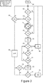
- the first step is to detect if the Auto-Access vehicle ride height adjustment system 100 is enabled. Enablement may be achieved through a vehicle set-up menu (not described herein) or some other appropriate means. If it is not enabled, the entire remaining process is avoided and the system maintains the suspension in its set position.
- the set position depends on the vehicle and may comprise any one of Sport, Road, Off-Road, Extended or other setting including Terrain Response (TM), an automatic system (not described further herein) which automatically sets the suspension (among other things) in response to changes detected in the terrain being traversed by the vehicle.
- TM Terrain Response
- Sport-mode may comprise a low ride height to lower the centre of gravity to facilitate fast cornering.
- Road-mode may be considered a normal mode at intermediate ride height for maximum comfort and handling on metalled surfaces.
- Off-Road-mode may comprise a relatively high ride height to give ground clearance on rough terrain.
- Extended-mode may be at maximum ride height for use over extremely rough terrain or when wading in deep water.
- the controller first checks 62 to establish the current state of the suspension. If not in a certain condition, the system does not proceed any further until it is at "normal" or a "Speed Lowered” height (which may be a lowered height for high speed of SUV type vehicles, where normal height is still relatively highly elevated).
- a "Speed Lowered” height which may be a lowered height for high speed of SUV type vehicles, where normal height is still relatively highly elevated.
- the doors are checked in step 64 to establish if they are open. If the doors are open, then this is because the system has not anticipated the end of the journey which has occurred unexpectedly.
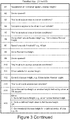
- step 66 all the conditions for lowering the suspension are checked and provided these are affirmative, the system, in step 68 lowers the suspension in one of the following ways:
- step 68 the driver may still manually select Full Access height in step 70, which if selected is effected in step 72. And, whether or not he/she has done so, should a condition be detected in step 74 that the Auto-Access system of the present invention should be exited, the suspension is changed to its normal height in step 76, or such other height as set or determined by the Terrain Response (TM) system. At this point, the system reverts back to the Start 50.
- TM Terrain Response
- step 78 detects whether or not an EOJ event is about to happen, that is, whether the system determines that passengers are about to disembark. This occurs when, for example, the seat belts are unbuckled or the ignition is disabled or when an EOJ event predictor determines that an EOJ event is about to occur with sufficient probability. If none of these conditions prevail, the system returns to the Start 50 but when they do and all Auto-Access conditions are satisfied (tested in step 80, which if not satisfied reverts the system back to the Start 50) the system lowers the suspension by a first amount in step 82. That amount may be 18 mm below normal ride height.
- step 84 The speed of the vehicle is then tested in step 84 and if it exceeds 40 kph (or another predetermined speed), the system reverts the suspension to normal ride height in step 86 and returns the system to the Start 50. However, if the speed does not exceed 40 kph, the state of doors of the vehicle is tested in step 88. If they are not open, the system cycles back to the speed test of step 84 until such time as the doors are opened. If, then, all the Auto-Access conditions are satisfied, tested in step 90, the suspension is lowered to its Full Access height in step 72, whereupon the system follows the procedure described above. However, if any one of those conditions are not satisfied, the system reverts to the speed test in step 84.
- Steps 66, 74, 80 and 90 are all the same step of testing that the vehicle is in a condition where the Auto Access can be invoked. These have been described above and are listed below under the title “Precautions”. This is a non-limiting non-exhaustive list of vehicle states that may or may not be required to pertain.
- the Auto Access functionality may include the following precautions:
- the suspension may be raised to access height, i.e. the first movement causes an initial raising of the suspension to an intermediate level and the second movement causes a second raising of the suspension to the full access height so that the vehicle is not so low, thereby facilitating a driver or passenger when egressing from the vehicle.
- the invention will operate as described herein except in so far as it will be raised in two stages as opposed to lowered in two stages when transitioning from normal height to access height.
Landscapes
- Engineering & Computer Science (AREA)
- Mechanical Engineering (AREA)
- Chemical & Material Sciences (AREA)
- Combustion & Propulsion (AREA)
- Transportation (AREA)
- Automation & Control Theory (AREA)
- Vehicle Body Suspensions (AREA)
Claims (15)
- Bodenfreiheiteinstellsystem (100) für ein Fahrzeug (10), wobei das System Folgendes umfasst:ein Aufhängungssystem (16), das einstellbar ist, um die Bodenfreiheit eines Fahrzeugs (10), in das es eingebaut ist, zu ändern;ein erstes Mittel, um ein vorläufiges Reiseende(end of journey - EOJ)ereignis zu erfassen;eine Steuervorrichtung (22), um das Aufhängungssystem (16) in einer ersten Bewegung als Reaktion auf die Erfassung des vorläufigen EOJ-Ereignisses einzustellen, um die Bodenfreiheit des Fahrzeugs (10) in Richtung einer Zugangsbodenfreiheit des Fahrzeugs (10) zu ändern, wobei die Zugangsbodenfreiheit eine vorbestimmte Bodenfreiheit ist, die das Aussteigen aus und das Einsteigen in das Fahrzeug (10) erleichtert; undein zweites Mittel zum Erfassen eines entscheidenden EOJ-Ereignisses, wobei, wenn die Bodenfreiheit des Fahrzeugs (10) von der Zugangsbodenfreiheit nach der ersten Bewegung verschieden bleibt, die Steuervorrichtung (22) angepasst ist, um das Aufhängungssystem (16) in einer zweiten Bewegung als Reaktion auf die Erfassung des entscheidenden EOJ-Ereignisses weiter einzustellen, um die Bodenfreiheit des Fahrzeugs (10) weiter in Richtung der Zugangsbodenfreiheit des Fahrzeugs (10) zu ändern.
- Bodenfreiheiteinstellsystem (100) nach Anspruch 1, wobei das erste und das zweite Mittel Folgendes umfassen:einen elektronischen Prozessor mit einem elektrischen Eingang zum Empfangen von Signalen, die das vorläufige EOJ-Ereignis und das entscheidende EOJ-Ereignis anzeigen; undeine elektronische Speichervorrichtung (24), die elektrisch mit dem elektronischen Prozessor gekoppelt ist und darin gespeicherte Anweisungen aufweist; wobeider Prozessor dazu konfiguriert ist, auf die Speichervorrichtung (24) zuzugreifen und die darin gespeicherten Anweisungen derart auszuführen, dass er als Reaktion auf das vorläufige EOJ-Ereignis und das entscheidende EOJ-Ereignis betriebsfähig ist, um das Aufhängungssystem (16) in der ersten und der zweiten Bewegung einzustellen.
- Bodenfreiheiteinstellsystem (100) nach Anspruch 1 oder 2, wobei:das entscheidende EOJ-Ereignis ein Öffnen einer Tür des Fahrzeugs (10) umfasst; und/oderdas vorläufige EOJ-Ereignis Folgenden ist:ein Zündsystem des Fahrzeugs (10) wird ausgeschaltet; oderein oder mehrere Sicherheitsgurte des Fahrzeugs (10) werden abgeschnallt.
- Bodenfreiheiteinstellsystem (100) nach Anspruch 1, 2 oder 3, Folgendes umfassend:die Steuervorrichtung (22), die angeordnet ist, um die Einstellung des Aufhängungssystems (16) in der zweiten Bewegung zu beenden, nachdem eine vorbestimmte maximale Änderung der Bodenfreiheit aufgetreten ist und/oder nachdem eine maximale Zeitspanne seit der Erfassung des entscheidenden EOJ-Ereignisses verstrichen ist, oder wenn das Fahrzeug (10) die Zugangsbodenfreiheit erreicht; und/oderoptional, wobei die zweite Bewegung nach 2 bis 4 Sekunden, optional nach 3 Sekunden und/oder nach zwischen 25 und 40 mm einer Änderung der Bodenfreiheit des Fahrzeugs (10) beendet wird; und/oderdie Steuervorrichtung (22), die angeordnet ist, um die Einstellung des Aufhängungssystems (16) in der ersten Bewegung zu beenden, nachdem eine vorbestimmte maximale Änderung der Bodenfreiheit aufgetreten ist, optional zwischen 15 und 25 mm Änderung der Bodenfreiheit des Fahrzeugs (10), ferner optional nach 18 mm, und/oder nachdem eine maximale Zeitspanne seit der Erfassung des vorläufigen EOJ-Ereignisses verstrichen ist, wobei die Änderungen der Bodenfreiheit optional Absenkungen der Bodenfreiheit sind.
- Bodenfreiheiteinstellsystem (100) nach einem der vorhergehenden Ansprüche, ferner umfassend ein Mittel zum Erfassen eines oder mehrerer Sperrparameter des Fahrzeugs (10), um zu verhindern, dass die Steuervorrichtung (22) das Aufhängungssystem (16) in der ersten und/oder der zweiten Bewegung einstellt.
- Bodenfreiheiteinstellsystem (100) nach Anspruch 5, wobei ein Sperrparameter Folgendes umfasst:a) Erfassung eines vorhergehenden Ereignisses des Ausschaltens des Zündsystems ohne ein nachfolgendes Türöffnungsereignis vor dem Wiedereinschalten der Zündung;b) Erfassung, dass ein Sicherheitsgurt des Fahrzeugs (10) abgeschnallt ist, ohne dass ein nachfolgendes bestätigendes Ereignis eintritt;c) Erfassung einer unzureichenden Kapazität des Aufhängungssystems (16), um die Änderung der Fahrzeugbodenfreiheit umzukehren, falls ein manueller Eingriff des Bodenfreiheiteinstellsystems (100) herbeigeführt werden sollte;d) Erfassung eines unebenen Grunds oder eines geneigten Grunds, auf dem das Fahrzeug (10) positioniert ist;e) Erfassung des Boden- oder des Wagenheberkontakts der Karosserie (14) des Fahrzeugs (10);f) Erfassung von Fahrzeugwaten; und/oderg) Erfassung des Abschleppens.
- Bodenfreiheiteinstellsystem (100) nach Anspruch 6, wobei das bestätigende Ereignis aus Folgenden ausgewählt ist:das Fahrzeug (10) kommt zum Stillstand, nachdem der Sicherheitsgurt des Fahrzeugs (10) innerhalb einer vorbestimmten Zeitspanne, optional innerhalb einer Minute, abgeschnallt wurde; undein Fahrzeug-EOJ-Vorhersagesystem sagt ein EOJ-Ereignis mit einem erforderlichen Vertrauensniveau voraus.
- Verfahren zum Bestimmen der Bodenfreiheit eines Fahrzeugs (10), die folgenden Schritte umfassend:Versehen des Fahrzeugs (10) mit einem Aufhängungssystem (16), das einstellbar ist, um die Bodenfreiheit eines Fahrzeugs (10), in das es eingebaut ist, zu ändern;Erfassen (78) eines vorläufigen Reiseende(end of journey - EOJ)ereignisses;unter Verwendung einer Steuervorrichtung, Einstellen (82) des Aufhängungssystem (16) in einer ersten Bewegung als Reaktion auf die Erfassung des vorläufigen EOJ-Ereignisses, um die Bodenfreiheit des Fahrzeugs (10) in Richtung einer Zugangsbodenfreiheit des Fahrzeugs (10) zu ändern, wobei die Zugangsbodenfreiheit eine vorbestimmte Bodenfreiheit ist, die das Aussteigen aus und das Einsteigen in das Fahrzeug (10) erleichtert;Erfassen (88) eines entscheidenden EOJ-Ereignisses; und,wenn die Bodenfreiheit des Fahrzeugs (10) von der Zugangsbodenfreiheit nach der ersten Bewegung verschieden bleibt, weiteres Einstellen (72) des Aufhängungssystems (16) in einer zweiten Bewegung als Reaktion auf die Erfassung des entscheidenden EOJ-Ereignisses, um die Bodenfreiheit des Fahrzeugs (10) weiter in Richtung der Zugangsbodenfreiheit des Fahrzeugs (10) zu ändern.
- Verfahren nach Anspruch 8, wobei:das entscheidende EOJ-Ereignis ein Öffnen einer Tür des Fahrzeugs (10) umfasst; und/oderdas vorläufige EOJ-Ereignis Folgenden ist:ein Zündsystem des Fahrzeugs (10) wird ausgeschaltet; oderein oder mehrere Sicherheitsgurte des Fahrzeugs (10) werden abgeschnallt.
- Verfahren nach Anspruch 8 oder 9, wobei die Einstellung des Aufhängungssystems (16) Folgendes umfasst:Beenden in der zweiten Bewegung, nachdem eine vorbestimmte maximale Änderung der Bodenfreiheit aufgetreten ist und/oder nachdem eine maximale Zeitspanne seit der Erfassung des entscheidenden EOJ-Ereignisses verstrichen ist, oder wenn das Fahrzeug (10) die Zugangsbodenfreiheit erreicht; undoptional, wobei das Beenden nach 2 bis 4 Sekunden oder nach 3 Sekunden und/oder nach zwischen 25 und 40 mm einer Änderung der Bodenfreiheit des Fahrzeugs (10) geschieht; undBeenden in der ersten Bewegung, nachdem eine vorbestimmte maximale Änderung der Bodenfreiheit aufgetreten ist, optional nach zwischen 15 und 25 mm Änderung der Bodenfreiheit des Fahrzeugs (10), ferner optional nach 18 mm, und/oder nachdem eine maximale Zeitspanne seit der Erfassung des vorläufigen EOJ-Ereignisses verstrichen ist.
- Verfahren nach einem der Ansprüche 8 bis 10, ferner umfassend das Erfassen von Sperrparametern des Fahrzeugs (10) und bei Erfassung eines oder mehrerer der Sperrparameter, Verhindern des Einstellens des Aufhängungssystems (16), in der ersten und/oder der zweiten Bewegung.
- Verfahren nach Anspruch 11, wobei ein Sperrparameter Folgendes umfasst:a) Erfassung eines vorhergehenden Ereignisses des Ausschaltens des Zündsystems ohne ein nachfolgendes Türöffnungsereignis vor dem Wiedereinschalten der Zündung;b) Erfassung, dass ein Sicherheitsgurt des Fahrzeugs (10) abgeschnallt ist, ohne dass ein nachfolgendes bestätigendes Ereignis eintritt;c) Erfassung einer unzureichenden Kapazität des Aufhängungssystems (16), um die Änderung der Fahrzeugbodenfreiheit umzukehren, falls ein manueller Eingriff des Bodenfreiheiteinstellsystems herbeigeführt werden sollte;d) Erfassung eines unebenen Grunds oder eines geneigten Grunds, auf dem das Fahrzeug (10) positioniert ist;e) Erfassung des Boden- oder des Wagenheberkontakts der Karosserie (14) des Fahrzeugs (10);f) Erfassung von Fahrzeugwaten; und/oderg) Erfassung des Abschleppens.
- Verfahren nach Anspruch 12, wobei das bestätigende Ereignis aus Folgenden ausgewählt ist:das Fahrzeug (10) kommt zum Stillstand, nachdem der Sicherheitsgurt des Fahrzeugs (10) innerhalb einer vorbestimmten Zeitspanne, optional innerhalb einer Minute, abgeschnallt wurde; undein Fahrzeug-EOJ-Vorhersagesystem sagt ein EOJ-Ereignis mit einem erforderlichen Vertrauensniveau voraus.
- Elektronische Steuervorrichtung (22) für ein Fahrzeug (10), der ein Speichermedium zugeordnet ist, in dem Anweisungen gespeichert sind, die, wenn sie von der Steuervorrichtung (22) ausgeführt werden, bewirken, dass die Bodenfreiheit des Fahrzeugs (10) gemäß dem Verfahren nach einem der Ansprüche 8 bis 13 eingestellt wird.
- Fahrzeug (10), enthaltend ein Bodenfreiheiteinstellsystem nach einem der Ansprüche 1 bis 7, oder angeordnet, um ein Verfahren nach einem der Ansprüche 8 bis 13 herbeizuführen, oder enthaltend eine elektronische Steuervorrichtung (22) nach Anspruch 14.
Applications Claiming Priority (2)
| Application Number | Priority Date | Filing Date | Title |
|---|---|---|---|
| GB1412115.6A GB2528065B (en) | 2014-07-08 | 2014-07-08 | Vehicle suspension systems |
| PCT/EP2015/065468 WO2016005385A1 (en) | 2014-07-08 | 2015-07-07 | Vehicle suspension systems |
Publications (2)
| Publication Number | Publication Date |
|---|---|
| EP3166807A1 EP3166807A1 (de) | 2017-05-17 |
| EP3166807B1 true EP3166807B1 (de) | 2020-02-05 |
Family
ID=51410784
Family Applications (1)
| Application Number | Title | Priority Date | Filing Date |
|---|---|---|---|
| EP15734394.8A Active EP3166807B1 (de) | 2014-07-08 | 2015-07-07 | Fahrzeugaufhängungssysteme |
Country Status (7)
| Country | Link |
|---|---|
| US (1) | US10300758B2 (de) |
| EP (1) | EP3166807B1 (de) |
| JP (1) | JP6353970B2 (de) |
| CN (1) | CN106660424A (de) |
| AU (1) | AU2015286792B2 (de) |
| GB (1) | GB2528065B (de) |
| WO (1) | WO2016005385A1 (de) |
Cited By (1)
| Publication number | Priority date | Publication date | Assignee | Title |
|---|---|---|---|---|
| EP4389472A1 (de) * | 2022-12-23 | 2024-06-26 | Nio Technology (Anhui) Co., Ltd | Funktionssicherheit für ein elektrofahrzeug im stillstand |
Families Citing this family (32)
| Publication number | Priority date | Publication date | Assignee | Title |
|---|---|---|---|---|
| US10464388B2 (en) * | 2015-07-30 | 2019-11-05 | Honda Motor Co., Ltd. | Vehicle in-wheel motor suspension |
| GB2545651B (en) * | 2015-12-18 | 2018-10-24 | Jaguar Land Rover Ltd | Door protection system and method |
| DE102016005539B4 (de) * | 2016-05-04 | 2023-10-26 | Zf Cv Systems Hannover Gmbh | Elektronische Niveauregelungsvorrichtung für luftgefederte Fahrzeuge, Verfahren und Steuereinheit zur elektronischen Niveauregelung |
| US10322688B2 (en) * | 2016-12-30 | 2019-06-18 | Textron Innovations Inc. | Controlling electrical access to a lithium battery on a utility vehicle |
| JP2020537609A (ja) * | 2017-09-28 | 2020-12-24 | サン−ゴバン パフォーマンス プラスチックス パンプス ゲゼルシャフト ミット ベシュレンクテル ハフツング | サスペンション・アセンブリ並びにその製造方法及び使用方法 |
| WO2019061502A1 (zh) * | 2017-09-30 | 2019-04-04 | 深圳市大疆创新科技有限公司 | 车辆悬挂调节方法、系统及可调悬挂的车辆 |
| US10850587B2 (en) * | 2017-10-11 | 2020-12-01 | Ford Global Technologies, Llc | System and method for evaporative emissions detection |
| US10864792B2 (en) * | 2018-05-23 | 2020-12-15 | Ford Global Technologies, Llc | Ride-height adjustment with leaf spring |
| US20200130454A1 (en) * | 2018-10-30 | 2020-04-30 | Air Lift Company | Method of operating vehicle control system |
| CN109733147B (zh) * | 2018-12-18 | 2020-09-22 | 珠海格力电器股份有限公司 | 一种车辆高度自动调节方法、系统、存储介质及车辆 |
| CN110370876B (zh) * | 2019-06-18 | 2024-02-02 | 上海蔚来汽车有限公司 | 悬架高度控制方法、交互设备、存储介质、控制器、车辆 |
| WO2021102335A1 (en) | 2019-11-21 | 2021-05-27 | Tesla, Inc. | Adjustable suspension for a vehicle |
| JP7226362B2 (ja) * | 2020-02-06 | 2023-02-21 | トヨタ自動車株式会社 | 車高調整装置 |
| GB2616995B (en) * | 2020-07-21 | 2024-10-23 | Jaguar Land Rover Ltd | Vehicle active suspension control system and method |
| GB2597460B (en) * | 2020-07-21 | 2023-03-29 | Jaguar Land Rover Ltd | Vehicle active suspension control system and method |
| GB2597458B (en) | 2020-07-21 | 2023-07-26 | Jaguar Land Rover Ltd | Vehicle active suspension control system and method |
| GB2597457B (en) * | 2020-07-21 | 2023-02-01 | Jaguar Land Rover Ltd | Vehicle active suspension control system and method |
| DE102020121497A1 (de) * | 2020-08-17 | 2022-02-17 | Zf Cv Systems Global Gmbh | Verfahren zum Ankoppeln eines Aufliegers an ein Zugfahrzeug, Ankoppel-Steuereinrichtung und Fahrzeug |
| GB2601347B (en) * | 2020-11-27 | 2023-05-24 | Jaguar Land Rover Ltd | Vehicle ramp angle control |
| KR102973653B1 (ko) * | 2021-03-24 | 2026-06-08 | 현대자동차주식회사 | 차량의 리저버 압력 제어 장치 및 그것의 동작 방법 |
| US20240408929A1 (en) * | 2021-10-18 | 2024-12-12 | Jaguar Land Rover Limited | Loss of a subsystem and interactions with external systems |
| JP7369817B2 (ja) * | 2022-03-30 | 2023-10-26 | 本田技研工業株式会社 | 電動サスペンション装置 |
| US11560034B1 (en) * | 2022-03-31 | 2023-01-24 | Rivian Ip Holdings, Llc | Situation-based vehicle configuration |
| US12623506B2 (en) | 2022-06-28 | 2026-05-12 | Hyundai Motor Company | Device and method for controlling a vehicle that supports vehicle boarding and exiting of passengers with mobility difficulties |
| CN115402235A (zh) * | 2022-08-22 | 2022-11-29 | 中国第一汽车股份有限公司 | 拖车模式控制方法、装置、设备及可读介质 |
| CN115848086A (zh) * | 2022-11-17 | 2023-03-28 | 浙江联控技术有限公司 | 车身高度调节方法、装置、电子设备及存储介质 |
| JP2024085542A (ja) * | 2022-12-15 | 2024-06-27 | 日産自動車株式会社 | 車高調整方法及び車高調整装置 |
| US12539737B2 (en) | 2022-12-29 | 2026-02-03 | Rivian Ip Holdings, Llc | Vehicle based accessory ventilation |
| CN116587792A (zh) * | 2023-06-13 | 2023-08-15 | 长城汽车股份有限公司 | 车身高度调节方法、车门外把手及车辆 |
| US12522038B2 (en) * | 2024-04-10 | 2026-01-13 | Ford Global Technologies, Llc | Methods and apparatus to facilitate a tire change |
| WO2025244965A1 (en) * | 2024-05-20 | 2025-11-27 | ClearMotion, Inc. | Methods and systems for controlling vehicle body motion and occupant experience |
| US12384217B1 (en) * | 2024-10-11 | 2025-08-12 | GM Global Technology Operations LLC | Water drainage systems and methods for vehicles |
Family Cites Families (21)
| Publication number | Priority date | Publication date | Assignee | Title |
|---|---|---|---|---|
| JPH01233111A (ja) * | 1988-03-12 | 1989-09-18 | Mazda Motor Corp | 車両用車高調整装置 |
| GB9119534D0 (en) | 1991-09-13 | 1991-10-23 | Dunlop Ltd | Vehicle suspension system |
| GB9213268D0 (en) * | 1992-06-23 | 1992-08-05 | Rover Group | A suspension system for a vehicle |
| DE59304539D1 (de) * | 1992-07-30 | 1997-01-02 | Abb Daimler Benz Transp | Sekundärfederung für schienenfahrzeuge |
| GB2346592B (en) * | 1999-02-13 | 2002-05-29 | Rover Group | A vehicle |
| EP1243447B1 (de) * | 2001-03-24 | 2005-12-21 | Continental Aktiengesellschaft | Geschlossene Niveauregelanlage für Fahrzeuge |
| JP2004345473A (ja) | 2003-05-21 | 2004-12-09 | Toyota Motor Corp | 車高調整装置 |
| DE102004017986A1 (de) * | 2004-04-14 | 2005-11-03 | Daimlerchrysler Ag | Einstiegshilfe für ein Fahrzeug, insbesondere für einen Personenkraftwagen |
| JP4506463B2 (ja) * | 2004-12-28 | 2010-07-21 | トヨタ自動車株式会社 | 車高調整装置 |
| JP2006224848A (ja) * | 2005-02-18 | 2006-08-31 | Toyota Motor Corp | サスペンション装置 |
| JP4519113B2 (ja) * | 2006-09-12 | 2010-08-04 | トヨタ自動車株式会社 | 車両用サスペンションシステム |
| JP4793577B2 (ja) | 2006-11-10 | 2011-10-12 | アイシン精機株式会社 | 車高調整装置 |
| JP2008293210A (ja) * | 2007-05-23 | 2008-12-04 | Aisin Aw Co Ltd | 車両用開扉支援装置、車両用開扉支援方法および車両用開扉支援プログラム |
| US8217755B2 (en) * | 2008-09-23 | 2012-07-10 | Unicell Limited | Vehicle with controlled door operation |
| FR2978941A1 (fr) * | 2011-08-12 | 2013-02-15 | Peugeot Citroen Automobiles Sa | Procede de controle des suspensions et des sieges d'un vehicule automobile |
| US8413997B1 (en) * | 2011-11-21 | 2013-04-09 | Air Lift Company | System for controlling a fluid suspension |
| GB201215963D0 (en) * | 2012-09-06 | 2012-10-24 | Jaguar Cars | Vehicle control system and method |
| US20140095023A1 (en) * | 2012-09-28 | 2014-04-03 | Tesla Motors, Inc. | Vehicle Air Suspension Control System |
| US9101519B2 (en) * | 2013-02-07 | 2015-08-11 | Dallas Smith Corporation | Leveling ramp for a wheelchair |
| US9272596B2 (en) * | 2013-06-21 | 2016-03-01 | Continental Automotive Systems, Inc. | GPS activated park mode for adjustable suspension systems |
| US9358854B1 (en) * | 2015-06-17 | 2016-06-07 | Link, Mfg., Ltd. | Air suspension control system for a vehicle |
-
2014
- 2014-07-08 GB GB1412115.6A patent/GB2528065B/en active Active
-
2015
- 2015-07-07 EP EP15734394.8A patent/EP3166807B1/de active Active
- 2015-07-07 JP JP2017501029A patent/JP6353970B2/ja active Active
- 2015-07-07 WO PCT/EP2015/065468 patent/WO2016005385A1/en not_active Ceased
- 2015-07-07 CN CN201580036815.8A patent/CN106660424A/zh active Pending
- 2015-07-07 US US15/324,648 patent/US10300758B2/en active Active
- 2015-07-07 AU AU2015286792A patent/AU2015286792B2/en active Active
Non-Patent Citations (1)
| Title |
|---|
| None * |
Cited By (1)
| Publication number | Priority date | Publication date | Assignee | Title |
|---|---|---|---|---|
| EP4389472A1 (de) * | 2022-12-23 | 2024-06-26 | Nio Technology (Anhui) Co., Ltd | Funktionssicherheit für ein elektrofahrzeug im stillstand |
Also Published As
| Publication number | Publication date |
|---|---|
| JP2017519684A (ja) | 2017-07-20 |
| EP3166807A1 (de) | 2017-05-17 |
| US10300758B2 (en) | 2019-05-28 |
| AU2015286792A1 (en) | 2017-03-02 |
| GB201412115D0 (en) | 2014-08-20 |
| GB2528065A (en) | 2016-01-13 |
| US20170203626A1 (en) | 2017-07-20 |
| GB2528065B (en) | 2018-07-04 |
| CN106660424A (zh) | 2017-05-10 |
| WO2016005385A1 (en) | 2016-01-14 |
| AU2015286792B2 (en) | 2018-10-04 |
| JP6353970B2 (ja) | 2018-07-04 |
Similar Documents
| Publication | Publication Date | Title |
|---|---|---|
| US10300758B2 (en) | Vehicle suspension systems | |
| CN108215792B (zh) | 确定车辆座椅的占用状态 | |
| US9393849B2 (en) | Vehicle height adjustment apparatus | |
| US11738758B2 (en) | Apparatus and method for monitoring vehicle operation | |
| US7035735B2 (en) | Method and device for automatically triggering a deceleration in a motor vehicle | |
| US10286744B2 (en) | Vehicle height adjustment device | |
| US20160272035A1 (en) | Vehicle height adjustment apparatus | |
| US20140025259A1 (en) | Method and system to detect and mitigate customer dissatisfaction with performance of automatic mode selection system | |
| US20160052351A1 (en) | Dynamic tire air pressure system | |
| US9809077B2 (en) | Method and apparatus for operating a cushioning system for a motor vehicle | |
| CN103608206B (zh) | 避免车辆碰撞的方法和车辆驾驶员辅助系统 | |
| KR101996420B1 (ko) | 보행자 충돌 시 충격 완화 장치 및 방법 | |
| US20060164227A1 (en) | Control device and priming method for an element protecting a vehicle passenger and/or a road user | |
| KR20180078979A (ko) | 보행자 충돌 시 충격 완화 장치 및 방법 | |
| US7349783B2 (en) | Supplemental restraint deployment method with anticipatory crash classification | |
| US20080071446A1 (en) | Method for Controlling a Safety-Relevant Component of a Motor Vehicle and Motor Vehicle Comprising a Preventively Activated Safety System | |
| JP3816840B2 (ja) | ブレーキ制御装置 | |
| WO2026045163A1 (zh) | 车辆数据处理方法 | |
| US11447149B2 (en) | Systems and methods for detecting and alerting load separation from a moving vehicle | |
| US20080300753A1 (en) | Method for Controlling a Belt Pretensioner and Safety Arrangement Comprising a Belt Pretensioner | |
| JP5313654B2 (ja) | 車両減速装置及び車両 | |
| EP3166806A1 (de) | End-of-journey-fahrzeugsysteme | |
| US20250289410A1 (en) | Vehicle control system fore tire instality incidents | |
| CN118025088A (zh) | 用于自动制动车辆的方法和设备 | |
| WO2026091041A1 (zh) | 悬架控制方法、装置和车辆 |
Legal Events
| Date | Code | Title | Description |
|---|---|---|---|
| STAA | Information on the status of an ep patent application or granted ep patent |
Free format text: STATUS: THE INTERNATIONAL PUBLICATION HAS BEEN MADE |
|
| PUAI | Public reference made under article 153(3) epc to a published international application that has entered the european phase |
Free format text: ORIGINAL CODE: 0009012 |
|
| STAA | Information on the status of an ep patent application or granted ep patent |
Free format text: STATUS: REQUEST FOR EXAMINATION WAS MADE |
|
| 17P | Request for examination filed |
Effective date: 20170208 |
|
| AK | Designated contracting states |
Kind code of ref document: A1 Designated state(s): AL AT BE BG CH CY CZ DE DK EE ES FI FR GB GR HR HU IE IS IT LI LT LU LV MC MK MT NL NO PL PT RO RS SE SI SK SM TR |
|
| AX | Request for extension of the european patent |
Extension state: BA ME |
|
| DAV | Request for validation of the european patent (deleted) | ||
| DAX | Request for extension of the european patent (deleted) | ||
| REG | Reference to a national code |
Ref country code: DE Ref legal event code: R079 Ref document number: 602015046409 Country of ref document: DE Free format text: PREVIOUS MAIN CLASS: B60G0017016000 Ipc: B60G0017016500 |
|
| RIC1 | Information provided on ipc code assigned before grant |
Ipc: B60G 17/016 20060101ALI20190618BHEP Ipc: B60G 17/0165 20060101AFI20190618BHEP Ipc: B60G 17/017 20060101ALI20190618BHEP Ipc: B60G 17/019 20060101ALI20190618BHEP |
|
| GRAP | Despatch of communication of intention to grant a patent |
Free format text: ORIGINAL CODE: EPIDOSNIGR1 |
|
| STAA | Information on the status of an ep patent application or granted ep patent |
Free format text: STATUS: GRANT OF PATENT IS INTENDED |
|
| GRAJ | Information related to disapproval of communication of intention to grant by the applicant or resumption of examination proceedings by the epo deleted |
Free format text: ORIGINAL CODE: EPIDOSDIGR1 |
|
| INTG | Intention to grant announced |
Effective date: 20190801 |
|
| GRAP | Despatch of communication of intention to grant a patent |
Free format text: ORIGINAL CODE: EPIDOSNIGR1 |
|
| INTG | Intention to grant announced |
Effective date: 20190903 |
|
| GRAS | Grant fee paid |
Free format text: ORIGINAL CODE: EPIDOSNIGR3 |
|
| GRAA | (expected) grant |
Free format text: ORIGINAL CODE: 0009210 |
|
| STAA | Information on the status of an ep patent application or granted ep patent |
Free format text: STATUS: THE PATENT HAS BEEN GRANTED |
|
| RBV | Designated contracting states (corrected) |
Designated state(s): AL AT BE BG CH CY CZ DE DK EE ES FI FR GR HR HU IE IS IT LI LT LU LV MC MK MT NL NO PL PT RO RS SE SI SK SM TR |
|
| AK | Designated contracting states |
Kind code of ref document: B1 Designated state(s): AL AT BE BG CH CY CZ DE DK EE ES FI FR GR HR HU IE IS IT LI LT LU LV MC MK MT NL NO PL PT RO RS SE SI SK SM TR |
|
| REG | Reference to a national code |
Ref country code: AT Ref legal event code: REF Ref document number: 1229650 Country of ref document: AT Kind code of ref document: T Effective date: 20200215 |
|
| REG | Reference to a national code |
Ref country code: DE Ref legal event code: R096 Ref document number: 602015046409 Country of ref document: DE |
|
| REG | Reference to a national code |
Ref country code: IE Ref legal event code: FG4D |
|
| REG | Reference to a national code |
Ref country code: CH Ref legal event code: EP |
|
| REG | Reference to a national code |
Ref country code: NL Ref legal event code: MP Effective date: 20200205 |
|
| PG25 | Lapsed in a contracting state [announced via postgrant information from national office to epo] |
Ref country code: NO Free format text: LAPSE BECAUSE OF FAILURE TO SUBMIT A TRANSLATION OF THE DESCRIPTION OR TO PAY THE FEE WITHIN THE PRESCRIBED TIME-LIMIT Effective date: 20200505 Ref country code: FI Free format text: LAPSE BECAUSE OF FAILURE TO SUBMIT A TRANSLATION OF THE DESCRIPTION OR TO PAY THE FEE WITHIN THE PRESCRIBED TIME-LIMIT Effective date: 20200205 Ref country code: PT Free format text: LAPSE BECAUSE OF FAILURE TO SUBMIT A TRANSLATION OF THE DESCRIPTION OR TO PAY THE FEE WITHIN THE PRESCRIBED TIME-LIMIT Effective date: 20200628 Ref country code: RS Free format text: LAPSE BECAUSE OF FAILURE TO SUBMIT A TRANSLATION OF THE DESCRIPTION OR TO PAY THE FEE WITHIN THE PRESCRIBED TIME-LIMIT Effective date: 20200205 |
|
| REG | Reference to a national code |
Ref country code: LT Ref legal event code: MG4D |
|
| PG25 | Lapsed in a contracting state [announced via postgrant information from national office to epo] |
Ref country code: BG Free format text: LAPSE BECAUSE OF FAILURE TO SUBMIT A TRANSLATION OF THE DESCRIPTION OR TO PAY THE FEE WITHIN THE PRESCRIBED TIME-LIMIT Effective date: 20200505 Ref country code: LV Free format text: LAPSE BECAUSE OF FAILURE TO SUBMIT A TRANSLATION OF THE DESCRIPTION OR TO PAY THE FEE WITHIN THE PRESCRIBED TIME-LIMIT Effective date: 20200205 Ref country code: SE Free format text: LAPSE BECAUSE OF FAILURE TO SUBMIT A TRANSLATION OF THE DESCRIPTION OR TO PAY THE FEE WITHIN THE PRESCRIBED TIME-LIMIT Effective date: 20200205 Ref country code: IS Free format text: LAPSE BECAUSE OF FAILURE TO SUBMIT A TRANSLATION OF THE DESCRIPTION OR TO PAY THE FEE WITHIN THE PRESCRIBED TIME-LIMIT Effective date: 20200605 Ref country code: HR Free format text: LAPSE BECAUSE OF FAILURE TO SUBMIT A TRANSLATION OF THE DESCRIPTION OR TO PAY THE FEE WITHIN THE PRESCRIBED TIME-LIMIT Effective date: 20200205 Ref country code: GR Free format text: LAPSE BECAUSE OF FAILURE TO SUBMIT A TRANSLATION OF THE DESCRIPTION OR TO PAY THE FEE WITHIN THE PRESCRIBED TIME-LIMIT Effective date: 20200506 |
|
| PG25 | Lapsed in a contracting state [announced via postgrant information from national office to epo] |
Ref country code: NL Free format text: LAPSE BECAUSE OF FAILURE TO SUBMIT A TRANSLATION OF THE DESCRIPTION OR TO PAY THE FEE WITHIN THE PRESCRIBED TIME-LIMIT Effective date: 20200205 |
|
| PG25 | Lapsed in a contracting state [announced via postgrant information from national office to epo] |
Ref country code: CZ Free format text: LAPSE BECAUSE OF FAILURE TO SUBMIT A TRANSLATION OF THE DESCRIPTION OR TO PAY THE FEE WITHIN THE PRESCRIBED TIME-LIMIT Effective date: 20200205 Ref country code: RO Free format text: LAPSE BECAUSE OF FAILURE TO SUBMIT A TRANSLATION OF THE DESCRIPTION OR TO PAY THE FEE WITHIN THE PRESCRIBED TIME-LIMIT Effective date: 20200205 Ref country code: ES Free format text: LAPSE BECAUSE OF FAILURE TO SUBMIT A TRANSLATION OF THE DESCRIPTION OR TO PAY THE FEE WITHIN THE PRESCRIBED TIME-LIMIT Effective date: 20200205 Ref country code: LT Free format text: LAPSE BECAUSE OF FAILURE TO SUBMIT A TRANSLATION OF THE DESCRIPTION OR TO PAY THE FEE WITHIN THE PRESCRIBED TIME-LIMIT Effective date: 20200205 Ref country code: EE Free format text: LAPSE BECAUSE OF FAILURE TO SUBMIT A TRANSLATION OF THE DESCRIPTION OR TO PAY THE FEE WITHIN THE PRESCRIBED TIME-LIMIT Effective date: 20200205 Ref country code: SM Free format text: LAPSE BECAUSE OF FAILURE TO SUBMIT A TRANSLATION OF THE DESCRIPTION OR TO PAY THE FEE WITHIN THE PRESCRIBED TIME-LIMIT Effective date: 20200205 Ref country code: SK Free format text: LAPSE BECAUSE OF FAILURE TO SUBMIT A TRANSLATION OF THE DESCRIPTION OR TO PAY THE FEE WITHIN THE PRESCRIBED TIME-LIMIT Effective date: 20200205 Ref country code: DK Free format text: LAPSE BECAUSE OF FAILURE TO SUBMIT A TRANSLATION OF THE DESCRIPTION OR TO PAY THE FEE WITHIN THE PRESCRIBED TIME-LIMIT Effective date: 20200205 |
|
| REG | Reference to a national code |
Ref country code: DE Ref legal event code: R097 Ref document number: 602015046409 Country of ref document: DE |
|
| REG | Reference to a national code |
Ref country code: AT Ref legal event code: MK05 Ref document number: 1229650 Country of ref document: AT Kind code of ref document: T Effective date: 20200205 |
|
| PLBE | No opposition filed within time limit |
Free format text: ORIGINAL CODE: 0009261 |
|
| STAA | Information on the status of an ep patent application or granted ep patent |
Free format text: STATUS: NO OPPOSITION FILED WITHIN TIME LIMIT |
|
| 26N | No opposition filed |
Effective date: 20201106 |
|
| PG25 | Lapsed in a contracting state [announced via postgrant information from national office to epo] |
Ref country code: AT Free format text: LAPSE BECAUSE OF FAILURE TO SUBMIT A TRANSLATION OF THE DESCRIPTION OR TO PAY THE FEE WITHIN THE PRESCRIBED TIME-LIMIT Effective date: 20200205 Ref country code: IT Free format text: LAPSE BECAUSE OF FAILURE TO SUBMIT A TRANSLATION OF THE DESCRIPTION OR TO PAY THE FEE WITHIN THE PRESCRIBED TIME-LIMIT Effective date: 20200205 |
|
| PG25 | Lapsed in a contracting state [announced via postgrant information from national office to epo] |
Ref country code: SI Free format text: LAPSE BECAUSE OF FAILURE TO SUBMIT A TRANSLATION OF THE DESCRIPTION OR TO PAY THE FEE WITHIN THE PRESCRIBED TIME-LIMIT Effective date: 20200205 Ref country code: MC Free format text: LAPSE BECAUSE OF FAILURE TO SUBMIT A TRANSLATION OF THE DESCRIPTION OR TO PAY THE FEE WITHIN THE PRESCRIBED TIME-LIMIT Effective date: 20200205 Ref country code: PL Free format text: LAPSE BECAUSE OF FAILURE TO SUBMIT A TRANSLATION OF THE DESCRIPTION OR TO PAY THE FEE WITHIN THE PRESCRIBED TIME-LIMIT Effective date: 20200205 |
|
| REG | Reference to a national code |
Ref country code: CH Ref legal event code: PL |
|
| REG | Reference to a national code |
Ref country code: BE Ref legal event code: MM Effective date: 20200731 |
|
| PG25 | Lapsed in a contracting state [announced via postgrant information from national office to epo] |
Ref country code: CH Free format text: LAPSE BECAUSE OF NON-PAYMENT OF DUE FEES Effective date: 20200731 Ref country code: IE Free format text: LAPSE BECAUSE OF NON-PAYMENT OF DUE FEES Effective date: 20200707 Ref country code: LU Free format text: LAPSE BECAUSE OF NON-PAYMENT OF DUE FEES Effective date: 20200707 Ref country code: LI Free format text: LAPSE BECAUSE OF NON-PAYMENT OF DUE FEES Effective date: 20200731 |
|
| PG25 | Lapsed in a contracting state [announced via postgrant information from national office to epo] |
Ref country code: BE Free format text: LAPSE BECAUSE OF NON-PAYMENT OF DUE FEES Effective date: 20200731 |
|
| PG25 | Lapsed in a contracting state [announced via postgrant information from national office to epo] |
Ref country code: TR Free format text: LAPSE BECAUSE OF FAILURE TO SUBMIT A TRANSLATION OF THE DESCRIPTION OR TO PAY THE FEE WITHIN THE PRESCRIBED TIME-LIMIT Effective date: 20200205 Ref country code: MT Free format text: LAPSE BECAUSE OF FAILURE TO SUBMIT A TRANSLATION OF THE DESCRIPTION OR TO PAY THE FEE WITHIN THE PRESCRIBED TIME-LIMIT Effective date: 20200205 Ref country code: CY Free format text: LAPSE BECAUSE OF FAILURE TO SUBMIT A TRANSLATION OF THE DESCRIPTION OR TO PAY THE FEE WITHIN THE PRESCRIBED TIME-LIMIT Effective date: 20200205 |
|
| PG25 | Lapsed in a contracting state [announced via postgrant information from national office to epo] |
Ref country code: MK Free format text: LAPSE BECAUSE OF FAILURE TO SUBMIT A TRANSLATION OF THE DESCRIPTION OR TO PAY THE FEE WITHIN THE PRESCRIBED TIME-LIMIT Effective date: 20200205 Ref country code: AL Free format text: LAPSE BECAUSE OF FAILURE TO SUBMIT A TRANSLATION OF THE DESCRIPTION OR TO PAY THE FEE WITHIN THE PRESCRIBED TIME-LIMIT Effective date: 20200205 |
|
| P01 | Opt-out of the competence of the unified patent court (upc) registered |
Effective date: 20230528 |
|
| PGFP | Annual fee paid to national office [announced via postgrant information from national office to epo] |
Ref country code: DE Payment date: 20250722 Year of fee payment: 11 |
|
| PGFP | Annual fee paid to national office [announced via postgrant information from national office to epo] |
Ref country code: FR Payment date: 20250725 Year of fee payment: 11 |