EP3165643B1 - Métier jacquard, face à face pour métier à tisser comprenant au moins un métier jacquard et procédé d'établissement d'un métier jacquard - Google Patents
Métier jacquard, face à face pour métier à tisser comprenant au moins un métier jacquard et procédé d'établissement d'un métier jacquard Download PDFInfo
- Publication number
- EP3165643B1 EP3165643B1 EP15192876.9A EP15192876A EP3165643B1 EP 3165643 B1 EP3165643 B1 EP 3165643B1 EP 15192876 A EP15192876 A EP 15192876A EP 3165643 B1 EP3165643 B1 EP 3165643B1
- Authority
- EP
- European Patent Office
- Prior art keywords
- bars
- setting
- position adjustment
- yarn moving
- sub
- Prior art date
- Legal status (The legal status is an assumption and is not a legal conclusion. Google has not performed a legal analysis and makes no representation as to the accuracy of the status listed.)
- Active
Links
- 238000009941 weaving Methods 0.000 title claims description 31
- 238000000034 method Methods 0.000 title claims description 15
- 230000007246 mechanism Effects 0.000 claims description 35
- 239000004744 fabric Substances 0.000 claims description 25
- 230000003993 interaction Effects 0.000 description 5
- 239000003086 colorant Substances 0.000 description 2
- 238000003780 insertion Methods 0.000 description 2
- 230000037431 insertion Effects 0.000 description 2
- 238000010276 construction Methods 0.000 description 1
Images


Classifications
-
- D—TEXTILES; PAPER
- D03—WEAVING
- D03C—SHEDDING MECHANISMS; PATTERN CARDS OR CHAINS; PUNCHING OF CARDS; DESIGNING PATTERNS
- D03C3/00—Jacquards
- D03C3/24—Features common to jacquards of different types
- D03C3/26—General arrangements of jacquards, or disposition in relation to loom
-
- D—TEXTILES; PAPER
- D03—WEAVING
- D03C—SHEDDING MECHANISMS; PATTERN CARDS OR CHAINS; PUNCHING OF CARDS; DESIGNING PATTERNS
- D03C3/00—Jacquards
- D03C3/24—Features common to jacquards of different types
-
- D—TEXTILES; PAPER
- D03—WEAVING
- D03D—WOVEN FABRICS; METHODS OF WEAVING; LOOMS
- D03D39/00—Pile-fabric looms
- D03D39/16—Double-plush looms, i.e. for weaving two pile fabrics face-to-face
-
- D—TEXTILES; PAPER
- D03—WEAVING
- D03D—WOVEN FABRICS; METHODS OF WEAVING; LOOMS
- D03D47/00—Looms in which bulk supply of weft does not pass through shed, e.g. shuttleless looms, gripper shuttle looms, dummy shuttle looms
- D03D47/34—Handling the weft between bulk storage and weft-inserting means
- D03D47/38—Weft pattern mechanisms
Definitions
- the present invention refers to a jacquard machine and a face-to-face weaving machine comprising at least one jacquard machine.
- the invention further refers to a method of setting up a jacquard machine.
- a module providing a yarn moving mechanism for moving one or a plurality of yarn moving elements, for example, heddles, in a jacquard machine is known.
- Such a known module is shown in Fig. 1 .
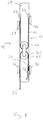
- the module 10 providing the yarn moving mechanism 12 has a hoist mechanism 14 with a cord 16 having hooks 18, 20 fixed to its ends. These hooks 18, 20 are provided for the cooperation with two knives 22, 24 which are arranged for a counter-phase movement for selectively moving the associated hooks 18, 20 between an upper position and a lower position.
- the hooks 18, 20 may be selected, for example, in their upper position, such as to be decoupled from the associated knives 22, 24.
- the cord 16 is guided around a first pulley 26.
- An output cord 28 of the yarn moving mechanism is guided around a second pulley 30.
- a downwardly extending output end 32 of the output cord 28 is connected to one or a plurality of yarn moving elements, for example, heddles.
- a connecting end 34 of the output cord 28 is connectable to a setting bar 36 by means of a hook 37 fixed to the connecting end 34.
- the setting bar 36 extends across a jacquard machine in a first direction which, when being provided in a weaving machine, substantially corresponds to the weft direction. In its two longitudinal end regions, the setting bar 36 is connected to position adjustment bars of the jacquard machine.
- a height position of the setting bar 36 i.e. the position in a height direction which is perpendicular with respect to the first and second directions, i.e. the weft direction and the warp direction, can be adjusted.
- This basis condition is primarily defined by a predefined positioning of the connecting end 34 of the output cord 28.
- each yarn moving element in a jacquard machine, a plurality of such yarn moving mechanisms are provided such that each yarn moving element can be moved for thereby moving an associated pile warp yarn for forming a shed.
- one such yarn moving mechanism in association with each yarn moving element, one such yarn moving mechanism can be provided.
- one such yarn moving mechanism may be arranged such as to cooperate with a plurality of yarn moving elements.
- a plurality of setting bars are provided, each setting bar extending in the first direction, i.e. the weft direction, and the setting bars being positioned following each other in the second direction, i.e. the warp direction, such that, for each yarn moving mechanism, there is a setting bar 36 for setting the basis condition thereof.
- each setting bar is provided for the cooperation with a plurality of yarn moving mechanisms arranged following each other in a first direction, i.e. the weft direction, and/or arranged immediately adjacent to each other in the warp direction.
- a jacquard machine according to the preamble part of claim 1 is known from DE 195 47 765 A1 .
- this object is achieved by a jacquard machine, comprising:
- each one of the setting bars can selectively be connected either to the one or the other one of the two position adjustment bars provided in a respective longitudinal end region of the setting bars allowing the selection of those two position adjustment bars, i.e. a pair of position adjustment bars, to which a respective setting bar has to be connected.
- groups and sub-groups of setting bars may be provided associated with different kinds of pile warp yarns used in a face-to-face weaving process.
- the pile warp yarns used in a face-to-face weaving process may comprise one kind of pile warp yarns which, when not being used for forming piles, i.e.
- each connecting means may comprise a first connecting member connected or connectable to a setting bar and a second connecting member connected or connectable to a position adjustment bar and connected to at least one first connecting member.
- the first connecting member of each one of the connecting means may be shiftable along the setting bar connected thereto.
- the first connecting member may comprise a receiving opening for shiftably receiving a shifting portion of the setting bar.
- locking means may be provided for locking the first connecting member to the setting bar at its longitudinal end region connected thereto in a first locking position and a second locking position, wherein in the first locking position the connecting means is positioned for connecting to one of the two position adjustment bars and in the second locking position the connecting means is positioned for connecting to the other one of the two position adjustment bars.
- At least one second connecting member may be connected to a plurality of first connecting members.
- each position adjustment bar extends in a second direction such as to be connectable to all setting bars, and/or each setting bar extends in the first direction substantially over all position adjustment bars such as to be connectable to each one of the position adjustment bars.
- the position adjustment bars may be supported by a supporting frame of the jacquard machine.
- a height position of the position adjustment bars in a height direction perpendicular to the first and second directions and/or an inclination of the position adjustment bars relative to a second direction may be variable.
- a face-to-face weaving machine may comprise at least one jacquard machine according to the present invention, wherein a plurality of pile warp yarns are provided extending in a warp direction and positioned adjacent to each other in a weft direction, each pile warp yarn having a yarn moving element of the at least one jacquard machine associated therewith for moving the pile warp yarns for forming a shed, wherein a first group of yarn moving elements of the at least one jacquard machine is associated with pile warp yarns to be incorporated in a top fabric when being dead piles and a second group of yarn moving elements of the at least one jacquard machine is associated with pile warp yarns to be incorporated in a bottom fabric when being dead piles, wherein the first group of yarn moving elements comprises a plurality of first sub-groups of yarn moving elements and the second group of yarn moving elements comprises a plurality of second sub-groups of yarn moving elements, wherein the first and second sub-groups of yarn moving elements are arranged alternately in the war
- the yarn moving elements associated with one particular kind of pile warp yarns are spread over an increased length in the warp direction as compared to an arrangement in which all the yarn moving elements of the first group are provided in one area adjacent to an other area where all the yarn moving elements of the second group are provided. Due to this spreading of the yarn moving elements of each one of the two groups over an increased length in the warp direction, the pile warp yarns can be easily moved in the height direction by means of the yarn moving elements for forming a shed with a reduced frictional interaction of immediately adjacent pile warp yarns, in particular with those layers of pile warp yarns incorporated into the fabrics as dead piles.
- each jacquard machine may comprise a plurality of setting bars extending substantially in the weft direction and positioned adjacent to each other substantially in the warp direction, each setting bar having two longitudinal end regions and a cooperation region arranged between the longitudinal end regions for the cooperation with a plurality of yarn moving mechanisms, for example, for setting a basis condition of the yarn moving mechanisms cooperating therewith, each yarn moving mechanism having an output cord connected to at least one yarn moving element, wherein a first group of setting bars is provided for the cooperation with yarn moving mechanisms connected to yarn moving elements of the first group of yarn moving elements and a second group of setting bars is provided for the cooperation with yarn moving mechanisms connected to yarn moving elements of the second group of yarn moving elements, wherein the first group of setting bars comprises a plurality of first sub-groups of setting bars, each first sub-group of setting bars being associated with one first sub-group of yarn moving elements, and comprises a plurality of second sub-groups of setting bars, each second sub-group of setting bars being associated
- each jacquard machine may comprise a plurality of position adjustment bars extending substantially in the warp direction, wherein in each longitudinal end region of the setting bars two position adjustment bars may be provided adjacent to each other, wherein the setting bars of the first sub-group of setting bars by means of connecting means are connected to the position adjustment bars of a first pair of position adjustment bars comprising one of the position adjustment bars positioned in a first one of the longitudinal end regions of the setting bars and one of the position adjustment bars positioned in a second one of the longitudinal end regions of the setting bars, and wherein the setting bars of the second sub-group of setting bars by means of connecting means are connected to the position adjustment bars of a second pair of position adjustment bars comprising the other one of the position adjustment bars positioned in the first longitudinal end region of the setting bars and the other one of the position adjustment bars positioned in the second longitudinal end region of the setting bars.
- first pair of position adjustment bars and the second pair of position adjustment bars may be inclined at different angles with respect to the warp direction.
- each group of yarn moving elements may be associated with pile warp yarns having the same color.
- the invention refers to a method of setting up a jacquard machine according to the present invention, preferably in a face-to-face weaving machine as described before, comprising the steps of:
- this setting up of one or a plurality of jacquard machines starts out from an other setup, in which the yarn moving elements are associated with respective groups or sub-groups of yarn moving elements, respectively, that differ from the ones of the new setup, and in which therefore there is an other association of setting bars with respective groups and subgroups, respectively, of setting bars, this may first of all require the disconnection of at least some of the setting bars from position adjustment bars to which they have been connected in the previous setup for then connecting these setting bars to the position adjustment bars in such a manner, that the alternating arrangement of first and second sub-groups of setting bars of the new setup is obtained.
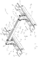
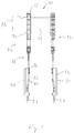
- Fig. 2 shows the essential portion of a jacquard machine generally denoted by 41.
- the not-shown portion of the jacquard machine 41 may be constructed in a conventional manner, for example, as known from WO 2014/076558 A2 .
- the yarn moving mechanisms for moving the yarn moving elements, for example, the heddles, of a jacquard machine may be constructed such as shown in WO 2014/076558 A2 and in Fig. 1 , respectively, and may comprise tackle arrangements for allowing three or four height positions of the yarn moving elements connected thereto.
- the jacquard machine 41 of the present invention comprises a plurality of setting bars generally denoted by 36.
- Fig. 2 four setting bars 36a, 36b, 36c, 36d are shown. All these setting bars 36 extend in a first direction D1, which, when being provided in a weaving machine, substantially corresponds to the weft direction WE.
- the setting bars 36 are arranged parallel to each other side by side in a second direction D2, which, when being installed in a weaving machine, substantially corresponds to the warp direction WA.
- Each of the setting bars 36 has two longitudinal end regions 38, 40 and has a cooperation region 42 between these longitudinal end regions 38, 40. In the cooperation region 42, the setting bars 36 are positioned for the cooperation with the yarn moving mechanisms, for example, in a manner as shown in Fig. 1 .
- two position adjustment bars 44, 46 and 48, 50 are provided in each one of the two end regions 38, 40 of the plate-shaped setting bars 36.
- the plate-shaped position adjustment bars 44, 46, 48, 50 are arranged parallel to each other such as to extend substantially in the second direction D2.
- the position adjustment bars 44, 46, 48, 50 are supported by a supporting frame of the jacquard machine 40, which, in Fig. 2 , is represented by the four supporting plates 60, 62, 64, 66.
- Each position adjustment bar 44, 46, 48, 50 is supported by the respective supporting plate 60, 62, 64, 66 by means of respective supporting screws 68 such that the height position of each longitudinal end region 52, 54, 56, 58 of the position adjustment bars 44, 46, 48, 50 in a height direction H, i.e. a direction which is substantially perpendicular to the first and second directions D1 and D2, can be adjusted.
- H a height direction which is substantially perpendicular to the first and second directions D1 and D2
- the height position of the entire position adjustment bars 44, 46, 48, 50 as well as their inclination relative to the second direction D2 can be adjusted. It is to be noted that the height position as well as the inclination can be individually adjusted for each one of the four position adjustment bars 44, 46, 48, 50.
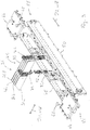
- Each one of the setting bars 36 extends in the first direction D1 over all position adjustment bars 44, 46, 48, 50 and is connected to two of the position adjustment bars 44, 46, 48, 50 by means of respective connecting means 72.
- respective connecting means 72 In each longitudinal end region 38, 40 of each setting bar 36, one such connecting means 72 is provided.
- Each connecting means 72 comprises a first connecting member 74 connected to a respective longitudinal end region 38, 40 of the associated setting bar 36 such as to be shiftable in the longitudinal direction of the setting bar 36 corresponding to the first direction D1.
- the first connecting members 74 have a slot-shaped receiving opening 76 adapted to the plate-shaped cross-section of the longitudinal end regions 38, 40 of the setting bars 36.
- the shifting portion 78 of the setting bars 36 provided in each one of the longitudinal end regions 38, 40 thereof the first connecting members 74 can be locked to the setting bar 36 by means of locking means 80.
- these locking means 80 may comprise a pretensioned locking member in each first connecting member 74 and locking grooves in the setting bar 36 receiving this pretensioned locking member when the first connecting member 74 is in one of the two obtainable locking positions.
- the first connecting members 74 are locked to the associated setting bars 36 at their outermost end, which, in Figs. 5 and 6 , is shown by means of a first connecting member 74 shown in broken lines.
- the first connecting members 74 can be brought to their second locking position shown in Figs. 5 and 6 by means of a first connecting member 74 shown in full lines.
- the connecting means 72 comprise plate-shaped second connecting members 82 which, by means of fastening screws 84, can be fixed to the position adjustment bars 44, 46, 48, 50.
- a height position adjustment screw 87 By means of a height position adjustment screw 87, the height position of a respective second connecting member 82 relative to an associated position adjustment bar 44, 46, 48, 50 can be selected.
- the second connecting member 82 can be fixed to the associated position adjustment bar 44, 46, 48, 50 by means of the fastening screws 84.
- the second connecting members 82 may be arranged such as to be connected to a plurality of first connecting members 74 by means of respective fastening screws 86. In the example shown in Fig. 6 , three first connecting members 74 associated with three immediately adjacent setting bars 36 can be connected to the same second connecting member 82.
- the first connecting members 74 may comprise a flexible connecting portion 88.
- the position adjustment bars 44, 46, 48, 50, to which a respective one of the setting bars 36 is connected can be selected.
- the connecting means 72 provided in the longitudinal end region 38 of the connecting bar 36a is in its first locking position such that this connecting means 72 can be connected to the position adjustment bar 44.
- the connecting means 72 provided in the other longitudinal end region 40 of this setting bar 36 is in its second locking position such that it can be connected to the position adjustment bar 48.
- the same arrangement has been selected in association with the setting bar 36b.
- the connecting means 72 provided at the longitudinal end regions 38 thereof are in their second locking position and therefore can be connected to the position adjustment bar 46.
- the connecting means 72 provided at the longitudinal end region 40 of the setting bars 36c and 36d are in their first locking position and therefore can be connected to the position adjustment bar 50.
- the position adjustment bars 44 and 48 provide a first pair P1 of position adjustment bars to which the setting bars of a first group GS1 of setting bars are connected, while the position adjustment bars 46, 50 provide a second pair P2 of position adjustment bars to which the setting bars of a second group GS2 of setting bars are connected. Due to the fact that the height position as well as the inclination of all the position adjustment bars 44, 46, 48, 50 can be individually adjusted, the height position of the setting bars of the first group GS1, i.e. the setting bars connected to the position adjustment bars 44, 48, and the height position of the setting bars of the second group GS2, i.e.
- the setting bars connected to the position adjustment bars 46, 50 can be set independently of each other by adjusting the height position and/or the angle of inclination of the two position adjustment bars 44, 48 of the first pair P1 differently from the height position and/or the angle of inclination of the position adjustment bars 46, 50 of the second pair P2.
- all the setting bars 36 extend in the first direction substantially over all the position adjustment bars 44, 46, 48, 50.
- the locking means 72 positioned in their first locking position, i.e. positioned at or near the outermost end of a respective setting bar 36, are positioned such that they can be connected to one of the two outermost adjustment bars 44 or 50.
- This does not require that the setting bars 36, in their respective longitudinal end regions 38, 40, extend beyond the two outermost adjustment bars 44, 50 in the first direction, but only requires such a length of the setting bars 36 that the connecting means 72, positioned in the first locking position, can be connected to one of the outermost adjustment bars 44, 50.
- such a jacquard machine may comprise only such setting bars 36 which can selectively be connected to either one of the two position adjustment bars arranged at the respective longitudinal end regions of the setting bars 36.
- additional setting bars not shown in the figures, which are arranged such as to be only connected or connectable to the one or the other one of the two position adjustment bars positioned at respective longitudinal end region of these setting bars.
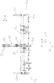
- a setup of the yarn moving elements 92 i.e. the heddles, provided in a weaving machine generally denoted by 90 will be explained.
- the yarn moving elements are shown in a position provided during one particular pick, i.e. one weft insertion cycle, in which a shed is formed for introducing a weft thread.
- one weft insertion cycle in which a shed is formed for introducing a weft thread.
- the yarn moving elements 92 are associated with groups G1 and G2.
- the first group G1 is subdivided into a plurality of sub-groups G1 a, G1 b, G1 c and G1 d.
- the second group G2 is subdivided into sub-groups G2a, G2b, G2c and G2d.
- Each one of these sub-groups G1 a, G1 b, G1 c, G1 d, G2a, G2b, G2c, G2d of yarn moving elements (92) may comprise a plurality of yarn moving elements (92) offset with respect to each other in the warp direction WA and in the weft direction WE.
- the yarn moving elements 92 of the first group G1 may be associated with pile warp yarns provided in a weaving machine extending in a warp direction WA and adjacent to each other in a weft direction WE, which is perpendicular to the drawing plane of Fig. 7 , which pile warp yarns are to be incorporated into a top fabric of the two fabrics to be woven by the face-to-face weaving machine 90 in a face-to-face weaving process when not being used for forming piles, i.e. when being dead piles.
- the pile warp yarns associated with the yarn moving elements 92 of the second group G2 may be pile warp yarns which, when not being used for forming piles, are to be incorporated into the bottom fabric of the two fabrics which are simultaneously woven in the face-to-face weaving process. It is to be noted that a pile warp yarn Y associated with a respective one of the yarn moving elements 92 may be guided through a respective eyelet 94 of this yarn moving element such that, by means of a movement of the yarn moving element 92 in the height direction H, the associated pile warp yarn can be moved in the height direction for forming the shed.
- the locations at which the associated pile warp yarns cooperate with the yarn moving elements of this group G1 are spread over an extended area in the warp direction WA.
- the locations at which the pile warp yarns associated with the yarn moving elements of the second group G2 interact with their associated yarn moving elements Due to this spreading of the locations of interaction, the frictional interaction of immediately adjacent pile warp yarns which, preferably, are associated with different sub-groups can be reduced such that an easier movement of the pile warp yarns in the height direction when forming the shed with a reduced frictional interaction of immediately adjacent pile warp yarns can be obtained.
- a pile warp yarn system comprising all the pile warp yarns extending through one dent may comprise eight pile warp yarns of different color.
- Four of these differently colored pile warp yarns are to be incorporated in the top fabric when being dead piles, while the other four differently colored pile warp yarns of each pile warp yarn system are to be incorporated in the bottom fabric when being dead piles.
- Each one of the sub-groups G1a, G1b, G1c, G1d, G2a, G2b, G2c, and G2d is provided for the interaction with pile warp yarns of one color.
- the yarn moving elements 92 of the first sub-group G1 a are provided for moving all the pile warp yarns of all the pile warp yarn systems having a first color
- the yarn moving elements 92 of the second sub-group G2a are provided for moving the pile warp yarns of all pile warp yarn systems having a second color, and so on.
- the number of yarn moving elements 92 in each one of the eight sub-groups corresponds to the number of pile warp yarn systems and the number of dents through which such pile warp yarn systems extend, respectively.
- the setting bars 36 may be provided in corresponding sub-groups of setting bars. There may be a corresponding alternating arrangement of first sub-groups GS1 a of setting bars and second sub-groups GS2a of setting bars in the second direction D2 corresponding to the warp direction.
- the setting bars 36a, 36b may be the setting bars of one first sub-group GS1 a of the first group GS1 of setting bars
- the setting bars 36c, 36d may be the setting bars of a second sub-group GS2a of the second group GS2 of setting bars.
- the first and second sub-groups of setting bars may be arranged in such an alternating manner.
- the height positions of the setting bars of the first sub-groups of setting bars can be adjusted independently of the height positions of the setting bars of all the second sub-groups of setting bars, such that the inclined arrangement of the eyelets 94 of the yarn moving elements associated with the first group G1, as can be seen in Fig. 7 , as well as another inclination of the immediately adjacent eyelets of the yarn moving elements of the second group G2 may be obtained by providing a corresponding adjustment of the position adjustment bars of the two pairs of position adjustment bars.
- the jacquard machine shown in Figs. 2 to 6 comprising all the setting bars and the position adjustment bars as well as the setting of yarn moving elements shown in Fig. 7 may be applied in a face-to-face weaving machine having two rapiers, i.e. two gripper mechanisms working at two different levels in the height direction, which requires the provision of three height positions of the yarn moving elements.
- the jacquard machine and the setting of the yarn moving elements may also be used in a face-to-face weaving machine having three rapiers, i.e. three gripper mechanisms working at three different height levels in the height direction, which requires the provision of four height positions of the yarn moving elements.
Claims (14)
- Machine Jacquard, comprenant:- une pluralité d'éléments de mouvement de fil (92) et en association avec chaque élément de mouvement de fil (92) un mécanisme de mouvement de fil (12) ayant un cordon de sortie (28) connecté à l'élément de mouvement de fil (92),- une pluralité de barres de réglage (36) s'étendant essentiellement dans un premier sens (D1) correspondant à un sens trame (WE) et positionnée de manière adjacente l'une à l'autre, essentiellement dans un deuxième sens (D2) correspondant à un sens chaîne (WA), chaque barre de réglage (36) ayant deux régions d'extrémité longitudinales (38, 40) et une région de coopération (42) arrangées entre les régions d'extrémité longitudinales (38, 40) pour la coopération avec une pluralité de mécanisme de mouvement de fil (12),- une pluralité de barres d'ajustement de position (44, 46, 48, 50) s'étendant essentiellement dans le deuxième sens (D2),- une pluralité de moyens de connexion (72) pour connecter les barres de réglage (36) aux barres d'ajustement de position (44, 46, 48, 50), caractérisé en ce que dans chacune des deux régions d'extrémité longitudinales (38, 40) des barres de réglage (36) deux barres d'ajustement de position (44, 46, 48, 50) sont prévues de manière adjacente l'une à l'autre, et en ce que dans chaque région d'extrémité longitudinale (38, 40) de chaque barre de réglage (36) un moyen de connexion (72) est prévu de manière à être connectable à l'une ou l'autre des deux barres d'ajustement de position (44, 46, 48, 50) arrangées dans une région respective des régions d'extrémité longitudinales (38, 40) des barres de réglage (36).
- Machine Jacquard selon la revendication 1, où chaque moyen de connexion (72) comprend un premier membre de connexion (74) connecté ou connectable à une barre de réglage (36) et un deuxième membre de connexion (82) connecté ou connectable à une barre d'ajustement de position (44, 46, 48, 50) et connecté à au moins un premier membre de connexion (74).
- Machine Jacquard selon la revendication 2, où le premier membre de connexion (74) est déplaçable le long de la barre de réglage (36) connectée à celui-ci.
- Machine Jacquard selon la revendication 3, où le premier membre de connexion (74) comprend une ouverture de réception (76) pour recevoir de manière déplaçable une portion de déplacement (78) de la barre de réglage (36).
- Machine Jacquard selon une des revendications 2 à 4, où des moyens de verrouillage (80) sont prévus pour verrouiller le premier membre de connexion (74) à la barre de réglage (36) à sa région d'extrémité longitudinale (38, 40) connectée à celle-ci dans une première position de verrouillage et une deuxième position de verrouillage, où dans la première position de verrouillage le moyen de connexion (72) est positionné pour la connexion à une des deux barres d'ajustement de position (44, 46, 48, 50) et dans la deuxième position de verrouillage le moyen de connexion est positionné pour la connexion à l'autre des deux barres d'ajustement de position (44, 46, 48, 50).
- Machine Jacquard selon une des revendications 2 à 5, où au moins un deuxième membre de connexion (82) est connecté à une pluralité de premiers membres de connexion (74).
- Machine Jacquard selon une des revendications 1 à 6, où chaque barre d'ajustement de position (44, 46, 48, 50) est étendue dans le deuxième sens (D2) pour être connectable à toutes les barres de réglage (36) et/ou où chaque barre de réglage (36) s'étend dans le premier sens (D1) essentiellement sur toutes les barres d'ajustement de position (44, 46, 48, 50) pour être connectable à chacune des barres d'ajustement de position (44, 46, 48, 50).
- Machine Jacquard selon une des revendications 1 à 7, où les barres d'ajustement de position (44, 46, 48, 50) sont supportées par une structure de support (60, 62, 64, 66) de la machine Jacquard (40) et/ou où une position de hauteur des barres d'ajustement de position (44, 46, 48, 50) dans un sens de hauteur perpendiculaire aux premier et deuxième sens (D1, D2) et/ou une inclinaison des barres d'ajustement de position (44, 46, 48, 50) relative au deuxième sens (D2) est variable.
- Machine à tisser double face, comprenant au moins une machine Jacquard (40) selon une des revendications précédentes où une pluralité de fils de chaîne de poil est prévue s'étendant dans un sens de chaîne (WA) et positionnée de manière adjacente l'un à l'autre dans un sens de trame (WE), chaque fil de chaîne de poil ayant un membre de mouvement de fil (92) de ladite au moins une machine Jacquard (40) associé à celui-ci pour bouger les fils de chaîne de poil pour former une foule, où un premier groupe (G1) d'éléments de mouvement de fil (92) de ladite au moins une machine Jacquard (40) est associé à des fils de chaîne de poil à être incorporé dans un tissu de haut lorsqu'il s'agit de poils non coupés et où un deuxième groupe (G2) d'éléments de mouvement de fil (92) de ladite au moins une machine Jacquard (40) est associé à des fils de chaîne de poil à être incorporé dans un tissu de bas lorsqu'il s'agit de poils non coupés, où le premier groupe (G1) d'éléments de mouvement de fil (92) comprend une pluralité de premiers sous-groupes (G1a, G1b, G1c, G1d) d'éléments de mouvement de fil (92) et le deuxième groupe (G2) d'éléments de mouvement de fil (92) comprend une pluralité de deuxièmes sous-groupes (G2a, G2b, G2c, G2d) d'éléments de mouvement de fil (92), où les premiers et deuxièmes sous-groupes (G1a, G1b, G1c, G1d, G2a, G2b, G2c, G2d) d'éléments de mouvement de fil (92) sont arrangés à tour de rôle dans le sens de chaîne (WA).
- Machine à tisser double face selon la revendication 9, où au moins une, de préférence chaque machine Jacquard (41) comprend une pluralité de barres de réglage (36) s'étendant essentiellement dans le sens de trame (WE) et positionnées de manière adjacente l'une à l'autre essentiellement dans le sens de chaîne (WA), chaque barre de réglage (36) ayant deux régions d'extrémité longitudinales (38, 40) et une région de coopération (42) arrangée entre les régions d'extrémité longitudinales (38, 40) pour la coopération avec une pluralité de mécanismes de mouvement de fil (12), chaque mécanisme de mouvement de fil (12) ayant un cordon de sortie (28) connecté à au moins un élément de mouvement de fil (92), où un premier groupe (GS1) de barres de réglage (36) est prévu pour la coopération avec des mécanismes de mouvement de fil (12) connectés à des éléments de mouvement de fil (92) du premier groupe (G1) d'éléments de mouvement de fil (92) et où un deuxième groupe (GS2) de barres de réglage (36) est prévu pour la coopération avec des mécanismes de mouvement de fil (12) connectés à des éléments de mouvement de fil (92) du deuxième groupe (G2) d'éléments de mouvement de fil (92), où le premier groupe (GS1) de barres de réglage (36) comprend une pluralité de premiers sous-groupes (GS1a) de barres de réglage (36), chaque premier sous-groupe (GS1a) de barres de réglage (36) étant associé avec un premier sous-groupe (G1a, G1b, G1c, G1d) d'éléments de mouvement de fil (92), et comprend une pluralité de deuxièmes sous-groupes (GS2a) de barres de réglage (36), chaque deuxième sous-groupe (GS2a) de barres de réglage (36) étant associé avec un deuxième sous-groupe (G2a, G2b, G2c, G2d) d'éléments de mouvement de fil (92), où les premiers et deuxièmes sous-groupes (GS1a, GS2a) de barres de réglage (36) sont arrangés à tour de rôle dans le sens de chaîne (WA).
- Machine à tisser double face selon la revendication 10, où au moins une, de préférence chaque machine Jacquard (41) comprend une pluralité de barres d'ajustement de position (44, 46, 48, 50) s'étendant essentiellement dans le sens de chaîne (WA), où dans chaque région d'extrémité longitudinale (38, 40) des barres de réglage (36) deux barres d'ajustement de position (44, 46, 48, 50) sont prévues de manière adjacente l'une à l'autre, où les barres de réglage (36) du premier sous-groupe (GS1a) de barres de réglage (36) sont connectées par des moyens de connexion (72) aux barres d'ajustement de position (44, 48) d'une première paire (P1) de barres d'ajustement de position comprenant une des barres d'ajustement de position (44, 46) positionnée dans une première des régions d'extrémité longitudinales (38, 40) des barres de réglage (36) et une des barres d'ajustement de position (48, 50) positionnée dans une deuxième des régions d'extrémité longitudinales (38, 40) des barres de réglage (36), et où les barres de réglage du deuxième sous-groupe (GS2a) de barres de réglage sont connectées par des moyens de connexion (72) aux barres d'ajustement de position (46, 50) d'une deuxième paire (P2) de barres d'ajustement de position comprenant l'autre des barres d'ajustement de position (44, 46) positionnée dans la première région d'extrémité longitudinale (38) des barres de réglage (36) et l'autre des barres d'ajustement de position (44, 48) positionnée dans la deuxième région d'extrémité longitudinale (40) des barres de réglage (36).
- Machine à tisser double face selon la revendication 11, où la première paire (P1) de barres d'ajustement de position et la deuxième paire (P2) de barres d'ajustement de position sont inclinées avec des angles différents par rapport au sens de chaîne (WA).
- Machine à tisser double face selon une des revendications 9 à 12, où chaque groupe (G1, G2) d'éléments de mouvement de fil (92) est associé avec des fils de chaîne poil ayant la même couleur.
- Procédé pour régler une machine Jacquard selon une des revendications 1 à 8, de préférence dans une machine à tisser double face selon une des revendications 9 à 13, comprenant les étapes suivantes :a) définir de premiers sous-groupes (G1a, G1b, G1c, G1d) d'éléments de mouvement de fil (92) prévus pour la coopération avec des fils de poil chaîne, à être incorporés dans un tissu de haut d'un tissu double face en tant que poils non coupés et définir de deuxièmes sous-groupes (G2a, G2b, G2c, G2d) d'éléments de mouvement de fil (92), prévus pour la coopération avec des fils de chaîne poil à être incorporés dans un tissu de bas d'un tissus double face en tant que poils non coupés, de sorte qu'il y a un arrangement alternant des premiers et deuxièmes sous-groupes (G1a, G1b, G1c, G1d, G2a, G2b, G2c, G2d) dans un sens (D2) correspondant essentiellement à un sens de chaîne (WA),b) en association avec l'arrangement alternant des premiers et deuxièmes sous-groupes (G1a, G1b, G1c, G1d, G2a, G2b, G2c, G2d) d'éléments de mouvement de fil (92) prévoir un arrangement alternant des premiers et deuxièmes sous-groupes (GS1a, GS2a) de barres de réglage (36) en connectant les barres de réglage (36a, 36b) des premiers sous-groupes (GS1a) de barres de réglage (36) dans chacune de leurs régions d'extrémité longitudinales (38, 40) à une des deux barres d'ajustement de position (44, 46, 48, 50) prévues dans chacune des deux régions d'extrémité longitudinales (38, 40) des barres de réglage (36) et connecter les barres de réglage (36c, 36d) des deuxièmes sous-groupes (GS2a) de barres de réglage (36) dans chacune des leurs deux régions d'extrémité longitudinales (38, 40) à l'autre des deux barres d'ajustement de position (44, 46, 48, 50) prévues dans chacune des deux régions d'extrémité longitudinales (38, 40) des barres de réglage (36), où au moins un, de préférence chaque sous-groupe (GS1a, GS2a) de barres de réglage (36) comprend une pluralité de barres de réglage (36) positionnées de manière adjacente l'une à l'autre dans un sens (D2) correspondant essentiellement au sens de chaîne (WA),c) connecter des mécanisme de mouvement de fil (12) associés aux éléments de mouvement de fil (92) des premiers sous-groupes (G1a, G1b, G1c, G1d) d'éléments de mouvement de fil (92) aux barres de réglage (36a, 36b) des premiers sous-groupes (GS1a) de barres de réglage (36) et connecter des mécanisme de mouvement de fil (12) associés aux éléments de mouvement de fil (92) des deuxièmes sous-groupes (G2a, G2b, G2c, G2d) d'éléments de mouvement de fil (92) aux barres de réglage (36c, 36d) des deuxièmes sous-groupes (GS2a) de barres de réglage (36).
Priority Applications (6)
| Application Number | Priority Date | Filing Date | Title |
|---|---|---|---|
| EP15192876.9A EP3165643B1 (fr) | 2015-11-04 | 2015-11-04 | Métier jacquard, face à face pour métier à tisser comprenant au moins un métier jacquard et procédé d'établissement d'un métier jacquard |
| CN201910830292.4A CN110512331B (zh) | 2015-11-04 | 2016-10-27 | 提花机以及设置提花机的方法 |
| EP16790547.0A EP3371356B1 (fr) | 2015-11-04 | 2016-10-27 | Métier jacquard, face à face pour métier à tisser comprenant au moins un métier jacquard et procédé d'établissement d'un métier jacquard |
| US15/772,556 US10508366B2 (en) | 2015-11-04 | 2016-10-27 | Jacquard machine, face-to-face weaving machine comprising at least one jacquard machine, and method of setting up a jacquard machine |
| PCT/EP2016/075988 WO2017076753A1 (fr) | 2015-11-04 | 2016-10-27 | Métier jacquard, métier à tisser double pièce comprenant au moins un métier jacquard, et procédé de réglage d'un métier jacquard |
| CN201680055811.9A CN108138390B (zh) | 2015-11-04 | 2016-10-27 | 提花机、包括至少一个提花机的面对面织机、以及设置提花机的方法 |
Applications Claiming Priority (1)
| Application Number | Priority Date | Filing Date | Title |
|---|---|---|---|
| EP15192876.9A EP3165643B1 (fr) | 2015-11-04 | 2015-11-04 | Métier jacquard, face à face pour métier à tisser comprenant au moins un métier jacquard et procédé d'établissement d'un métier jacquard |
Publications (2)
| Publication Number | Publication Date |
|---|---|
| EP3165643A1 EP3165643A1 (fr) | 2017-05-10 |
| EP3165643B1 true EP3165643B1 (fr) | 2018-04-18 |
Family
ID=54476770
Family Applications (2)
| Application Number | Title | Priority Date | Filing Date |
|---|---|---|---|
| EP15192876.9A Active EP3165643B1 (fr) | 2015-11-04 | 2015-11-04 | Métier jacquard, face à face pour métier à tisser comprenant au moins un métier jacquard et procédé d'établissement d'un métier jacquard |
| EP16790547.0A Active EP3371356B1 (fr) | 2015-11-04 | 2016-10-27 | Métier jacquard, face à face pour métier à tisser comprenant au moins un métier jacquard et procédé d'établissement d'un métier jacquard |
Family Applications After (1)
| Application Number | Title | Priority Date | Filing Date |
|---|---|---|---|
| EP16790547.0A Active EP3371356B1 (fr) | 2015-11-04 | 2016-10-27 | Métier jacquard, face à face pour métier à tisser comprenant au moins un métier jacquard et procédé d'établissement d'un métier jacquard |
Country Status (4)
| Country | Link |
|---|---|
| US (1) | US10508366B2 (fr) |
| EP (2) | EP3165643B1 (fr) |
| CN (2) | CN108138390B (fr) |
| WO (1) | WO2017076753A1 (fr) |
Families Citing this family (2)
| Publication number | Priority date | Publication date | Assignee | Title |
|---|---|---|---|---|
| EP3112509A1 (fr) * | 2015-07-02 | 2017-01-04 | NV Michel van de Wiele | Pièce de raccordement pour éléments de raccord d'un mécanisme de formation de foule d'un métier à tisser |
| EP3702500B1 (fr) * | 2019-02-26 | 2022-04-06 | STÄUBLI BAYREUTH GmbH | Procédé de tissage de tissus à poils et tissu à poils tissé à l'aide d'un tel procédé |
Family Cites Families (21)
| Publication number | Priority date | Publication date | Assignee | Title |
|---|---|---|---|---|
| BE1000304A5 (nl) * | 1987-02-13 | 1988-10-11 | Wiele Michel Nv Van De | Opengaap-jacquardmachine waarvan de takelinrichting door middel van op en neer beweegbare planken in blok gestuurd wordt. |
| BE1000885A5 (nl) * | 1987-08-27 | 1989-05-02 | Wiele Michel Van De Nv | Werkwijze en inrichting voor het weven van weefsels door middel van roedenweefmachines. |
| FR2647473B1 (fr) * | 1989-05-24 | 1991-07-26 | Staubli Verdol | Perfectionnements aux mecaniques d'armure a trois positions |
| BE1004347A3 (nl) * | 1990-05-31 | 1992-11-03 | Wiele Michel Van De Nv | Takelophanging voor een jacquardmachine en jacquardmachine voorzien van een dergelijke takelophanging. |
| BE1005823A3 (nl) * | 1992-05-19 | 1994-02-08 | Wiele Michel Van De Nv | Takelinrichting voor jacquardmachine. |
| BE1008209A4 (nl) * | 1993-04-23 | 1996-02-13 | Wiele Michel Van De Nv | Jacquardmachine. |
| FR2715666B1 (fr) * | 1994-01-28 | 1996-05-03 | Staubli Verdol | Mécanique d'armure propre à engendrer quatre positions des fils de chaîne d'un métier à tisser. |
| BE1008975A5 (nl) * | 1994-12-20 | 1996-10-01 | Wiele Michel Van De Nv | Jacquardmachine met takelinrichting. |
| AT406965B (de) * | 1998-09-17 | 2000-11-27 | Wis Engineering Gmbh & Co Kg | Vorrichtung zur fachbildung für eine jacquardmaschine |
| BE1014840A4 (nl) * | 2002-05-21 | 2004-05-04 | Wiele Michel Van De Nv | Grijper voor een axminstergrijperweefmachine. |
| CN1215210C (zh) * | 2002-09-03 | 2005-08-17 | 弘生集团有限公司 | 电子提花机的通丝导向装置 |
| US20040216797A1 (en) * | 2003-04-30 | 2004-11-04 | Staubli Corporation | Shed-forming mechanism, weaving loom of jacquard type and method for adjusting the number or type of warp yarns of such a loom |
| BE1015529A3 (nl) * | 2003-05-20 | 2005-05-03 | Wiele Michel Van De Nv | Inrichting voor het bevestigen en geleiden van een of meerdere takelkoorden in een jacquardmachine. |
| DE502004004436D1 (de) * | 2004-06-18 | 2007-09-06 | Schoenherr Textilmaschinenbau | Verfahren und Vorrichtung zur Fachbildung jacquardgemusterter Polkettfäden auf einer Doppelflorwebmaschine |
| BE1017094A3 (nl) * | 2006-04-05 | 2008-02-05 | Wiele Michel Van De Nv | Werkwijze voor het weven van poolweefsels met variabele poolhoogte. |
| BE1017367A4 (nl) * | 2006-11-17 | 2008-07-01 | Wiele Michel Van De Nv | Weefmachine voor het weven van poolweefsels, en set van minstens twee afstandshouders voorzien om naast elkaar gemonteerd te worden in een weefmachine voor het weven van poolweefsels. |
| EP2251467B1 (fr) * | 2009-05-13 | 2013-08-07 | SCHÖNHERR Textilmaschinenbau GmbH | Procédé de tisser simultanément deux étoffes, étoffe tissée selon ce procédé et machine à tisser utilisable avec ce procédé |
| BE1021506B1 (nl) | 2012-11-19 | 2015-12-03 | Nv Michel Van De Wiele | Module geschikt voor inbouw in een jaquardmachine |
| BE1021026B1 (nl) * | 2013-01-09 | 2015-01-27 | Nv Michel Van De Wiele | Tapijt met een schaduweffect en werkwijze voor het weven van een tapijtweefsel met een schaduweffect. |
| CN203821023U (zh) * | 2014-01-24 | 2014-09-10 | 东阳市映泰工贸有限公司 | 一种提花导向头装置 |
| CN104894723A (zh) * | 2015-05-26 | 2015-09-09 | 芜湖品度电子科技有限公司 | 提花机 |
-
2015
- 2015-11-04 EP EP15192876.9A patent/EP3165643B1/fr active Active
-
2016
- 2016-10-27 EP EP16790547.0A patent/EP3371356B1/fr active Active
- 2016-10-27 CN CN201680055811.9A patent/CN108138390B/zh active Active
- 2016-10-27 CN CN201910830292.4A patent/CN110512331B/zh active Active
- 2016-10-27 US US15/772,556 patent/US10508366B2/en active Active
- 2016-10-27 WO PCT/EP2016/075988 patent/WO2017076753A1/fr active Application Filing
Non-Patent Citations (1)
| Title |
|---|
| None * |
Also Published As
| Publication number | Publication date |
|---|---|
| CN108138390B (zh) | 2020-01-17 |
| WO2017076753A1 (fr) | 2017-05-11 |
| EP3371356B1 (fr) | 2021-03-17 |
| EP3371356A1 (fr) | 2018-09-12 |
| CN110512331B (zh) | 2020-11-10 |
| CN108138390A (zh) | 2018-06-08 |
| US10508366B2 (en) | 2019-12-17 |
| CN110512331A (zh) | 2019-11-29 |
| US20180320295A1 (en) | 2018-11-08 |
| EP3165643A1 (fr) | 2017-05-10 |
Similar Documents
| Publication | Publication Date | Title |
|---|---|---|
| US7086424B2 (en) | Method and system for weaving fabrics with two useable sides | |
| EP1900861B1 (fr) | Procédé de tissage d'une étoffe et étoffe tissée selon ce procédé | |
| EP3402917B1 (fr) | Tissu, notamment une moquette et procédé de tissage d'un tissu | |
| EP3371356B1 (fr) | Métier jacquard, face à face pour métier à tisser comprenant au moins un métier jacquard et procédé d'établissement d'un métier jacquard | |
| EP2943604B1 (fr) | Procédé pour tisser des tissus à poils et pour configurer un métier à tisser pour ceux-ci | |
| EP1746190B1 (fr) | Procédé pour tisser un tissu et un tissu tissé selon ce procédé | |
| US4858654A (en) | Pulley-block drive open shed jacquard machine | |
| EP0571461A1 (fr) | Tissage multiaxial. | |
| EP3339486B1 (fr) | Tissu et procédé de tissage d'un tissu, en particulier une moquette | |
| US6186186B1 (en) | Method and weaving machine for weaving a pile fabric | |
| EP2929072B1 (fr) | Module approprié à une installation dans une machine jacquard | |
| CN105926140B (zh) | 一种可用于织造三维正交多层织物的织样机及其织造方法 | |
| CN110168156B (zh) | 织边装置 | |
| DE19651799A1 (de) | Antriebsvorrichtung für die Fachbildeelemente von Webmaschinen | |
| JP3504673B2 (ja) | 織機綜絖と該綜絖を具備したジャカード織機 | |
| CN106120115B (zh) | 一种可改变织口位置的织样机及其织造方法 | |
| EP3440247B1 (fr) | Module de formation de foule pour dispositif de tissage | |
| CN212316358U (zh) | 提花机换型装置 | |
| CN113136647A (zh) | 提花机换型装置及提花机换型方法 | |
| EP2099965B1 (fr) | Procédé de tissage avec une croisure accrue de chaîne et métier à tisser pour effectuer le procédé | |
| EP0860527B1 (fr) | Système de sélection de trame à commande électronique pour métiers à tisser | |
| DE85309C (fr) | ||
| WO1979000759A1 (fr) | Methode de reglage de la largeur d'une etoffe sur un metier a tisser |
Legal Events
| Date | Code | Title | Description |
|---|---|---|---|
| PUAI | Public reference made under article 153(3) epc to a published international application that has entered the european phase |
Free format text: ORIGINAL CODE: 0009012 |
|
| AK | Designated contracting states |
Kind code of ref document: A1 Designated state(s): AL AT BE BG CH CY CZ DE DK EE ES FI FR GB GR HR HU IE IS IT LI LT LU LV MC MK MT NL NO PL PT RO RS SE SI SK SM TR |
|
| AX | Request for extension of the european patent |
Extension state: BA ME |
|
| 17P | Request for examination filed |
Effective date: 20170607 |
|
| RBV | Designated contracting states (corrected) |
Designated state(s): AL AT BE BG CH CY CZ DE DK EE ES FI FR GB GR HR HU IE IS IT LI LT LU LV MC MK MT NL NO PL PT RO RS SE SI SK SM TR |
|
| GRAP | Despatch of communication of intention to grant a patent |
Free format text: ORIGINAL CODE: EPIDOSNIGR1 |
|
| INTG | Intention to grant announced |
Effective date: 20171016 |
|
| GRAJ | Information related to disapproval of communication of intention to grant by the applicant or resumption of examination proceedings by the epo deleted |
Free format text: ORIGINAL CODE: EPIDOSDIGR1 |
|
| GRAS | Grant fee paid |
Free format text: ORIGINAL CODE: EPIDOSNIGR3 |
|
| GRAP | Despatch of communication of intention to grant a patent |
Free format text: ORIGINAL CODE: EPIDOSNIGR1 |
|
| INTC | Intention to grant announced (deleted) | ||
| INTG | Intention to grant announced |
Effective date: 20180212 |
|
| GRAA | (expected) grant |
Free format text: ORIGINAL CODE: 0009210 |
|
| AK | Designated contracting states |
Kind code of ref document: B1 Designated state(s): AL AT BE BG CH CY CZ DE DK EE ES FI FR GB GR HR HU IE IS IT LI LT LU LV MC MK MT NL NO PL PT RO RS SE SI SK SM TR |
|
| REG | Reference to a national code |
Ref country code: GB Ref legal event code: FG4D |
|
| REG | Reference to a national code |
Ref country code: CH Ref legal event code: EP |
|
| REG | Reference to a national code |
Ref country code: AT Ref legal event code: REF Ref document number: 990584 Country of ref document: AT Kind code of ref document: T Effective date: 20180515 |
|
| REG | Reference to a national code |
Ref country code: IE Ref legal event code: FG4D |
|
| REG | Reference to a national code |
Ref country code: DE Ref legal event code: R096 Ref document number: 602015010070 Country of ref document: DE |
|
| REG | Reference to a national code |
Ref country code: DE Ref legal event code: R082 Ref document number: 602015010070 Country of ref document: DE Representative=s name: RUTTENSPERGER LACHNIT TROSSIN GOMOLL PATENT- U, DE Ref country code: DE Ref legal event code: R082 Ref document number: 602015010070 Country of ref document: DE Representative=s name: RUTTENSPERGER LACHNIT TROSSIN GOMOLL, PATENT- , DE |
|
| REG | Reference to a national code |
Ref country code: NL Ref legal event code: MP Effective date: 20180418 |
|
| REG | Reference to a national code |
Ref country code: LT Ref legal event code: MG4D |
|
| PG25 | Lapsed in a contracting state [announced via postgrant information from national office to epo] |
Ref country code: NL Free format text: LAPSE BECAUSE OF FAILURE TO SUBMIT A TRANSLATION OF THE DESCRIPTION OR TO PAY THE FEE WITHIN THE PRESCRIBED TIME-LIMIT Effective date: 20180418 |
|
| PG25 | Lapsed in a contracting state [announced via postgrant information from national office to epo] |
Ref country code: ES Free format text: LAPSE BECAUSE OF FAILURE TO SUBMIT A TRANSLATION OF THE DESCRIPTION OR TO PAY THE FEE WITHIN THE PRESCRIBED TIME-LIMIT Effective date: 20180418 Ref country code: AL Free format text: LAPSE BECAUSE OF FAILURE TO SUBMIT A TRANSLATION OF THE DESCRIPTION OR TO PAY THE FEE WITHIN THE PRESCRIBED TIME-LIMIT Effective date: 20180418 Ref country code: SE Free format text: LAPSE BECAUSE OF FAILURE TO SUBMIT A TRANSLATION OF THE DESCRIPTION OR TO PAY THE FEE WITHIN THE PRESCRIBED TIME-LIMIT Effective date: 20180418 Ref country code: BG Free format text: LAPSE BECAUSE OF FAILURE TO SUBMIT A TRANSLATION OF THE DESCRIPTION OR TO PAY THE FEE WITHIN THE PRESCRIBED TIME-LIMIT Effective date: 20180718 Ref country code: FI Free format text: LAPSE BECAUSE OF FAILURE TO SUBMIT A TRANSLATION OF THE DESCRIPTION OR TO PAY THE FEE WITHIN THE PRESCRIBED TIME-LIMIT Effective date: 20180418 Ref country code: NO Free format text: LAPSE BECAUSE OF FAILURE TO SUBMIT A TRANSLATION OF THE DESCRIPTION OR TO PAY THE FEE WITHIN THE PRESCRIBED TIME-LIMIT Effective date: 20180718 Ref country code: PL Free format text: LAPSE BECAUSE OF FAILURE TO SUBMIT A TRANSLATION OF THE DESCRIPTION OR TO PAY THE FEE WITHIN THE PRESCRIBED TIME-LIMIT Effective date: 20180418 Ref country code: LT Free format text: LAPSE BECAUSE OF FAILURE TO SUBMIT A TRANSLATION OF THE DESCRIPTION OR TO PAY THE FEE WITHIN THE PRESCRIBED TIME-LIMIT Effective date: 20180418 |
|
| PG25 | Lapsed in a contracting state [announced via postgrant information from national office to epo] |
Ref country code: GR Free format text: LAPSE BECAUSE OF FAILURE TO SUBMIT A TRANSLATION OF THE DESCRIPTION OR TO PAY THE FEE WITHIN THE PRESCRIBED TIME-LIMIT Effective date: 20180719 Ref country code: HR Free format text: LAPSE BECAUSE OF FAILURE TO SUBMIT A TRANSLATION OF THE DESCRIPTION OR TO PAY THE FEE WITHIN THE PRESCRIBED TIME-LIMIT Effective date: 20180418 Ref country code: LV Free format text: LAPSE BECAUSE OF FAILURE TO SUBMIT A TRANSLATION OF THE DESCRIPTION OR TO PAY THE FEE WITHIN THE PRESCRIBED TIME-LIMIT Effective date: 20180418 Ref country code: RS Free format text: LAPSE BECAUSE OF FAILURE TO SUBMIT A TRANSLATION OF THE DESCRIPTION OR TO PAY THE FEE WITHIN THE PRESCRIBED TIME-LIMIT Effective date: 20180418 |
|
| REG | Reference to a national code |
Ref country code: DE Ref legal event code: R097 Ref document number: 602015010070 Country of ref document: DE |
|
| PG25 | Lapsed in a contracting state [announced via postgrant information from national office to epo] |
Ref country code: RO Free format text: LAPSE BECAUSE OF FAILURE TO SUBMIT A TRANSLATION OF THE DESCRIPTION OR TO PAY THE FEE WITHIN THE PRESCRIBED TIME-LIMIT Effective date: 20180418 Ref country code: CZ Free format text: LAPSE BECAUSE OF FAILURE TO SUBMIT A TRANSLATION OF THE DESCRIPTION OR TO PAY THE FEE WITHIN THE PRESCRIBED TIME-LIMIT Effective date: 20180418 Ref country code: EE Free format text: LAPSE BECAUSE OF FAILURE TO SUBMIT A TRANSLATION OF THE DESCRIPTION OR TO PAY THE FEE WITHIN THE PRESCRIBED TIME-LIMIT Effective date: 20180418 Ref country code: SK Free format text: LAPSE BECAUSE OF FAILURE TO SUBMIT A TRANSLATION OF THE DESCRIPTION OR TO PAY THE FEE WITHIN THE PRESCRIBED TIME-LIMIT Effective date: 20180418 Ref country code: DK Free format text: LAPSE BECAUSE OF FAILURE TO SUBMIT A TRANSLATION OF THE DESCRIPTION OR TO PAY THE FEE WITHIN THE PRESCRIBED TIME-LIMIT Effective date: 20180418 |
|
| PLBE | No opposition filed within time limit |
Free format text: ORIGINAL CODE: 0009261 |
|
| STAA | Information on the status of an ep patent application or granted ep patent |
Free format text: STATUS: NO OPPOSITION FILED WITHIN TIME LIMIT |
|
| PG25 | Lapsed in a contracting state [announced via postgrant information from national office to epo] |
Ref country code: SM Free format text: LAPSE BECAUSE OF FAILURE TO SUBMIT A TRANSLATION OF THE DESCRIPTION OR TO PAY THE FEE WITHIN THE PRESCRIBED TIME-LIMIT Effective date: 20180418 |
|
| 26N | No opposition filed |
Effective date: 20190121 |
|
| PG25 | Lapsed in a contracting state [announced via postgrant information from national office to epo] |
Ref country code: SI Free format text: LAPSE BECAUSE OF FAILURE TO SUBMIT A TRANSLATION OF THE DESCRIPTION OR TO PAY THE FEE WITHIN THE PRESCRIBED TIME-LIMIT Effective date: 20180418 |
|
| REG | Reference to a national code |
Ref country code: CH Ref legal event code: PL |
|
| PG25 | Lapsed in a contracting state [announced via postgrant information from national office to epo] |
Ref country code: MC Free format text: LAPSE BECAUSE OF FAILURE TO SUBMIT A TRANSLATION OF THE DESCRIPTION OR TO PAY THE FEE WITHIN THE PRESCRIBED TIME-LIMIT Effective date: 20180418 Ref country code: LU Free format text: LAPSE BECAUSE OF NON-PAYMENT OF DUE FEES Effective date: 20181104 |
|
| REG | Reference to a national code |
Ref country code: IE Ref legal event code: MM4A |
|
| PG25 | Lapsed in a contracting state [announced via postgrant information from national office to epo] |
Ref country code: LI Free format text: LAPSE BECAUSE OF NON-PAYMENT OF DUE FEES Effective date: 20181130 Ref country code: CH Free format text: LAPSE BECAUSE OF NON-PAYMENT OF DUE FEES Effective date: 20181130 |
|
| PG25 | Lapsed in a contracting state [announced via postgrant information from national office to epo] |
Ref country code: FR Free format text: LAPSE BECAUSE OF NON-PAYMENT OF DUE FEES Effective date: 20181130 Ref country code: IE Free format text: LAPSE BECAUSE OF NON-PAYMENT OF DUE FEES Effective date: 20181104 |
|
| PG25 | Lapsed in a contracting state [announced via postgrant information from national office to epo] |
Ref country code: MT Free format text: LAPSE BECAUSE OF NON-PAYMENT OF DUE FEES Effective date: 20181104 |
|
| PG25 | Lapsed in a contracting state [announced via postgrant information from national office to epo] |
Ref country code: PT Free format text: LAPSE BECAUSE OF FAILURE TO SUBMIT A TRANSLATION OF THE DESCRIPTION OR TO PAY THE FEE WITHIN THE PRESCRIBED TIME-LIMIT Effective date: 20180418 |
|
| PG25 | Lapsed in a contracting state [announced via postgrant information from national office to epo] |
Ref country code: CY Free format text: LAPSE BECAUSE OF FAILURE TO SUBMIT A TRANSLATION OF THE DESCRIPTION OR TO PAY THE FEE WITHIN THE PRESCRIBED TIME-LIMIT Effective date: 20180418 Ref country code: HU Free format text: LAPSE BECAUSE OF FAILURE TO SUBMIT A TRANSLATION OF THE DESCRIPTION OR TO PAY THE FEE WITHIN THE PRESCRIBED TIME-LIMIT; INVALID AB INITIO Effective date: 20151104 Ref country code: MK Free format text: LAPSE BECAUSE OF NON-PAYMENT OF DUE FEES Effective date: 20180418 |
|
| PG25 | Lapsed in a contracting state [announced via postgrant information from national office to epo] |
Ref country code: IS Free format text: LAPSE BECAUSE OF FAILURE TO SUBMIT A TRANSLATION OF THE DESCRIPTION OR TO PAY THE FEE WITHIN THE PRESCRIBED TIME-LIMIT Effective date: 20180818 |
|
| GBPC | Gb: european patent ceased through non-payment of renewal fee |
Effective date: 20191104 |
|
| PG25 | Lapsed in a contracting state [announced via postgrant information from national office to epo] |
Ref country code: GB Free format text: LAPSE BECAUSE OF NON-PAYMENT OF DUE FEES Effective date: 20191104 |
|
| REG | Reference to a national code |
Ref country code: AT Ref legal event code: UEP Ref document number: 990584 Country of ref document: AT Kind code of ref document: T Effective date: 20180418 |
|
| PGFP | Annual fee paid to national office [announced via postgrant information from national office to epo] |
Ref country code: BE Payment date: 20221118 Year of fee payment: 8 |
|
| P01 | Opt-out of the competence of the unified patent court (upc) registered |
Effective date: 20230517 |
|
| PGFP | Annual fee paid to national office [announced via postgrant information from national office to epo] |
Ref country code: TR Payment date: 20231102 Year of fee payment: 9 Ref country code: IT Payment date: 20231124 Year of fee payment: 9 Ref country code: DE Payment date: 20231121 Year of fee payment: 9 Ref country code: AT Payment date: 20231121 Year of fee payment: 9 |
|
| PGFP | Annual fee paid to national office [announced via postgrant information from national office to epo] |
Ref country code: BE Payment date: 20231120 Year of fee payment: 9 |