EP3402917B1 - Tissu, notamment une moquette et procédé de tissage d'un tissu - Google Patents
Tissu, notamment une moquette et procédé de tissage d'un tissu Download PDFInfo
- Publication number
- EP3402917B1 EP3402917B1 EP17700901.6A EP17700901A EP3402917B1 EP 3402917 B1 EP3402917 B1 EP 3402917B1 EP 17700901 A EP17700901 A EP 17700901A EP 3402917 B1 EP3402917 B1 EP 3402917B1
- Authority
- EP
- European Patent Office
- Prior art keywords
- weft
- yarns
- warp
- pile
- yarn
- Prior art date
- Legal status (The legal status is an assumption and is not a legal conclusion. Google has not performed a legal analysis and makes no representation as to the accuracy of the status listed.)
- Active
Links
- 239000004744 fabric Substances 0.000 title claims description 171
- 238000009941 weaving Methods 0.000 title claims description 50
- 238000000034 method Methods 0.000 title claims description 29
- 230000000694 effects Effects 0.000 claims description 16
- 235000014676 Phragmites communis Nutrition 0.000 claims description 6
- 230000007704 transition Effects 0.000 description 10
- 238000003780 insertion Methods 0.000 description 4
- 230000037431 insertion Effects 0.000 description 4
Images

Classifications
-
- D—TEXTILES; PAPER
- D03—WEAVING
- D03D—WOVEN FABRICS; METHODS OF WEAVING; LOOMS
- D03D27/00—Woven pile fabrics
- D03D27/02—Woven pile fabrics wherein the pile is formed by warp or weft
- D03D27/10—Fabrics woven face-to-face, e.g. double velvet
-
- D—TEXTILES; PAPER
- D03—WEAVING
- D03D—WOVEN FABRICS; METHODS OF WEAVING; LOOMS
- D03D13/00—Woven fabrics characterised by the special disposition of the warp or weft threads, e.g. with curved weft threads, with discontinuous warp threads, with diagonal warp or weft
- D03D13/004—Woven fabrics characterised by the special disposition of the warp or weft threads, e.g. with curved weft threads, with discontinuous warp threads, with diagonal warp or weft with weave pattern being non-standard or providing special effects
-
- D—TEXTILES; PAPER
- D03—WEAVING
- D03D—WOVEN FABRICS; METHODS OF WEAVING; LOOMS
- D03D27/00—Woven pile fabrics
- D03D27/02—Woven pile fabrics wherein the pile is formed by warp or weft
- D03D27/06—Warp pile fabrics
-
- D—TEXTILES; PAPER
- D10—INDEXING SCHEME ASSOCIATED WITH SUBLASSES OF SECTION D, RELATING TO TEXTILES
- D10B—INDEXING SCHEME ASSOCIATED WITH SUBLASSES OF SECTION D, RELATING TO TEXTILES
- D10B2503/00—Domestic or personal
- D10B2503/04—Floor or wall coverings; Carpets
Definitions
- the present invention relates to a fabric, for example, a carpet, having a shadow effect.
- the invention further relates to a method of weaving a fabric, for example, a carpet, having a shadow effect.
- WO 2013/041938 A2 discloses a fabric and a method of weaving a fabric.
- a fabric is woven such that, in a transition area, three weft yarns extend through a weft receiving opening defined between two crossings of a pair of binding warp yarns following each other in the warp direction. Two of these weft yarns extend on the back side with respect to a tension warp yarn providing a weft separating warp yarn, while a third one of the weft yarns extends on the pile side with respect to the tension warp yarn.
- a pile forming pile warp yarn is interlaced with the one of the two weft yarns positioned on the back side with respect to the tension warp yarn and positioned between the other two weft yarns in the warp direction, such as to extend out of the backing fabric between this intermediate weft yarn and the other two weft yarns constituting end weft yarns positioned immediately adjacent to one of the two crossings.
- a pile forming pile warp yarn is interlaced with the two weft yarns extending on the back side with respect to the tension warp yarn, such as to extend out of the backing fabric between one of these two weft yarns constituting an intermediate weft yarn and the weft yarn extending on the pile side with respect to the tension warp yarn and constituting an end weft yarn, on the one hand, and between the other one of these two weft yarns constituting an end weft yarn and a weft yarn not extending through this weft receiving opening, on the other hand.
- EP 2 894 244 A1 discloses a pile fabric and a method for weaving a pile fabric.
- a backing fabric is woven by using pairs of binding warp yarns repeatedly crossing each other for providing weft receiving openings, weft yarns extending through the weft receiving openings, and filling warp yarns.
- Three weft yarns extending through each one of the weft receiving openings are positioned such as to be separated in a direction from a pile side to a backside by at least one of the filling warp yarns.
- a pile forming pile warp yarn is interlaced with one of these three weft yarns extending through a respective weft receiving opening positioned at the back side with respect to the filling warp yarns and between the other two weft yarns positioned immediately adjacent to the two crossings of the binding warp yarns defining a respective weft receiving opening, thereby constituting end weft yarns.
- the piles provided by such a pile forming pile warp yarn extend out of the backing fabric between the intermediate weft yarn and each one of the two end weft yarns.
- a pile forming pile warp yarn is interlaced with the intermediate weft yarn and one of the two end weft yarns and extends out of the backing fabric between this end weft yarn and an end weft yarn of an immediately adjacent weft receiving opening, on the one hand, and between the intermediate weft yarn and the other one of the two end weft yarns, on the other hand.
- this object is achieved by a fabric, in particular a carpet, having a shadow effect, comprising:
- the tension warp yarns may be moved by the same means as used for moving the other yarns of the backing fabric.
- the expression "the majority of” means at least 50% of a particular structural element is provided in a particular manner.
- At least one pile may comprise two pile legs, one of the pile legs extending out of the backing fabric between the end weft yarn and the intermediate weft yarn and the other pile leg extending out of the backing fabric between the end weft yarn and an end weft yarn of an immediately adjacent weft receiving opening.
- at least one pile may comprise a single pile leg extending out of the backing fabric between the end weft yarn and the intermediate weft yarn or at least one pile may comprise a single pile leg extending out of the backing fabric between the end weft yarn and an end weft yarn of an immediately adjacent weft receiving opening.
- a pile in association with at least one weft receiving opening, may be provided by interlacing a pile warp yarn with an end weft yarn of this weft receiving opening positioned immediately adjacent to the crossing of the binding warp yarns defining this weft receiving opening in a first orientation of the warp direction and, in association with at least one other weft receiving opening, a pile may be provided by interlacing a pile warp yarn with an end weft yarn of this weft receiving opening positioned immediately adjacent to the crossing of the binding warp yarns defining this weft receiving opening in a second orientation of the warp direction, and/or in association with at least one weft receiving opening, preferably the majority of the weft receiving openings (O), most preferably each weft receiving opening, only one pile may be provided.
- Such a single pile may have one or two pile legs.
- the piles will have different inclinations with respect to the surface of the fabric.
- the selection of the direction of inclination of a respective pile is made by selecting an end weft yarn and the position of an end weft yarn within a weft receiving opening, respectively, for interlacing with a pile warp yarn. Therefore, there is no need for introducing a change of the ground weave of the backing fabric for allowing the changing of the direction of inclination of the piles.
- the necessary direction of inclination of the piles in different areas of the fabric is determined and correspondingly the positions of the end weft yarns within the weft receiving openings either at the one end or the other end in the warp direction are selected for interlacing with the pile warp yarns.
- pile warp yarns not used for forming piles are bound into the backing fabric such as to extend substantially in the warp direction as dead pile warp yarns, and that at least one, preferably each intermediate weft yarn of at least one weft receiving opening is separated from both end weft yarns of this weft receiving opening by at least one tension warp yarn and at least one, preferably all the dead pile warp yarns extending in the area of this weft receiving opening.
- pile warp yarns not used for forming piles may be bound into the backing fabric such as to extend substantially in the warp direction as dead pile warp yarns, and at least one, preferably each intermediate weft yarn of at least one weft receiving opening may be separated from a first one of the two end weft yarns of this weft receiving opening only by at least one tension warp yarn and may be separated from the second one of the two end weft yarns of this weft receiving opening by at least one tension warp yarn and at least one, preferably all the dead pile warp yarns extending in the area of this weft receiving opening.
- a pile is formed by interlacing a pile warp yarn with the second one of the two end weft yarns of this weft receiving opening.
- the first one of the two end weft yarns of this weft receiving opening may be arranged on the pile side relative to the dead pile warp yarns extending in the area of this weft receiving opening and the second one of the two end weft yarns of this weft receiving opening may be arranged on the back side relative to the dead pile warp yarns extending in the area of this weft receiving opening.
- At least one weft receiving opening preferably the majority of the weft receiving openings, most preferably each weft receiving opening, at least three weft yarns, preferably exactly three weft yarns, extend.
- These three weft yarns may comprise two weft yarns providing the two end weft yarns and one intermediate weft yarn extending substantially in the weft direction. This means that only three weft yarns, what means exactly three weft yarns, extending through such weft receiving openings are needed for providing one pile. However, there may be weft receiving openings through which more than three weft yarns extend.
- a plurality of warp yarn systems may be provided following each other in the weft direction, at least one warp yarn system, preferably the majority of warp yarn systems, most preferably each warp yarn system, comprising two binding warp yarns crossing each other, at least one tension warp yarn, and at least one, preferably a plurality of pile warp yarns, wherein in the pile warp yarn systems piles are provided by the pile warp yarns of a respective pile warp yarn system by interlacing these pile warp yarns with weft yarns extending through the weft receiving openings provided by the binding warp yarns of the same pile warp yarn system, preferably such that, by means of the pile warp yarns of each one of the warp yarn systems, one row of piles substantially extending in the warp direction is provided.
- binding warp yarns extending in the warp direction in close proximity to each other in the weft direction are used for forming weft receiving openings and the pile warp yarns are interlaced with weft yarns extending through such weft receiving openings, while at the same time warp yarns of such a warp yarn system are used as weft separating warp yarns generating the offset of the intermediate weft yarns with respect to the end weft yarns.
- This leads to a defined positioning of the weft yarns in the direction perpendicular with respect to the plane defined by the weft direction and the warp direction and leads to a defined positioning of the weft yarns in the warp direction in the region of each weft receiving opening.
- Such a defined positioning of the weft yarns in turn leads to a defined positioning of the piles extending out of the backing fabric and therefore leads to a clear shadow effect on the surface of such a fabric.
- weft yarns for example, may be the two end weft yarns provided in a respective weft receiving opening, relative to the at least one intermediate weft yarn in at least one weft receiving opening, preferably the majority of these weft receiving openings, most preferably each weft receiving opening, the two weft yarns positioned immediately adjacent to the two crossings of the binding warp yarns defining this weft receiving opening are not separated by a tension warp yarn.
- the ground weave of the backing fabric provided by the binding warp yarns, the tension warp yarns, and the weft yarns is the same.
- the relative positioning of the weft yarns extending through respective weft receiving openings in particular with respect to the tension warp yarns is the same.
- the crossings of the binding warp yarns defining the weft receiving openings in the two orientations of the warp direction may be located at the same position in the warp direction.
- the object is achieved by a method of weaving a fabric, in particular a carpet, having a shadow effect, preferably a fabric according to the present invention, wherein for weaving a backing fabric binding warp yarns are provided crossing each other for providing weft receiving openings, such that each weft receiving opening is defined in the warp direction by two crossings of binding warp yarns, wherein tension warp yarns are provided extending substantially in the warp direction and in association with at least one weft receiving opening, preferably the majority of weft receiving openings, most preferably each weft receiving opening, weft yarns are provided extending through this weft receiving opening substantially in the weft direction, such that the weft yarns positioned immediately adjacent to the two crossings defining this weft receiving opening in the warp direction are provided as end weft yarns positioned at a back side relative to at least one weft separating warp yarn, and at least one intermediate weft yarn positioned substantially between the two end wef
- pile warp yarns not used for forming piles may be bound into the backing fabric such as to extend substantially in the warp direction as dead pile warp yarns, and at least one, preferably each intermediate weft yarn of at least one weft receiving opening may be separated from both end weft yarns of this weft receiving opening by at least one tension warp yarn and at least one, preferably all the dead pile yarns extending in the area of this weft receiving opening.
- pile warp yarns not used for forming piles may be bound into the backing fabric such as to extend substantially in the warp direction as dead pile warp yarns, and at least one, preferably each intermediate weft yarn of at least one weft receiving opening may be separated from a first one of the two end weft yarns of this weft receiving opening only by at least one tension warp yarn and may be separated from the second one of the two end weft yarns of this weft receiving opening by at least one tension warp yarn and at least one, preferably all of the dead pile yarns extending in the area of this weft receiving opening.
- a pile may be formed by interlacing a pile warp yarn with the second one of the two end weft yarns of this weft receiving opening, and/or preferably wherein the first one of the two end weft yarns of this weft receiving opening is arranged on the pile side relative to the dead pile warp yarns extending in the area of this weft receiving opening and the second one of the two end weft yarns of this weft receiving opening is arranged on the back side relative to the dead pile warp yarns extending in the area of this weft receiving opening.
- a plurality of warp yarn systems may be provided following each other in the weft direction, at least one warp yarn system, preferably the majority of warp yarn systems, most preferably each warp yarn system, comprising two binding warp yarns crossing each other, at least one tension warp yarn, and at least one, preferably a plurality of pile warp yarns, wherein in the pile warp yarn systems piles are provided by the pile warp yarns of a respective pile warp yarn system by interlacing these pile warp yarns with weft yarns extending through the weft receiving openings provided by the binding warp yarns of the same pile warp yarn system, preferably such that, by means of the pile warp yarns of each one of the warp yarn systems, one row of piles substantially extending in the warp direction is provided.
- At least one warp yarn system may be provided in association with at least one, preferably each reed dent of a weaving machine.
- a defined association of the warp yarn systems with the reed dents a defined positioning of the weft yarns provided such as to extend through respective weft receiving openings generated by the crossing binding warp yarns of the warp yarn systems is obtained.
- the method may be a face-to-face weaving method for simultaneously weaving two fabrics.
- each warp yarn system may comprise the warp yarns for both fabrics to be woven.
- the crossings of the binding warp yarns of one of the two fabrics to be woven may be offset relative to the crossings of the binding warp yarns of the other one of the fabrics to be woven in the warp direction. In this way, the same direction of inclination of the piles provided in the two fabrics can be obtained. Further in at least one of the fabrics the crossings of the binding warp yarns defining the weft receiving openings in the two orientations of the warp direction are located at the same position in the warp direction, which may also be the case if, with the method of the present invention, only a single fabric is to be woven.
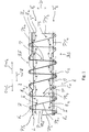
- Fig. 1 shows as a sectional view the weaving structure of two fabrics F 1 , F 2 commonly woven in a face-to-face weaving method according to the present invention.
- Fig. 1 shows the time sequence of the insertion of weft yarns and the interlacing of warp yarns with these weft yarns.
- weft insertion means for example, rapiers, one being inserted in the top fabric F 1 and one being inserted in the bottom fabric F 2 .
- the weft yarns may become shifted in the warp direction WA, such that in the fabrics F 1 , F 2 the positioning of the weft yarns relative to each other in the warp direction WA may be somewhat different as compared to the positioning shown in Fig. 1 .
- Each one of the fabrics F 1 , F 2 is constituted by a plurality of warp yarn systems comprising binding warp yarns B 1 , B 2 and tension warp yarns T for providing the ground weave of respective backing fabrics BF as well as pile warp yarns PY 1 , PY 2 , PY 3 , PY 4 for providing piles P extending out of the backing fabrics BF on a pile side PS.
- Each warp yarn system may comprise all the warp yarns for providing a ground weave of the two backing fabrics BF for both fabrics F 1 , F 2 and all the pile warp yarns PY 1 , PY 2 , PY 3 , PY 4 interlaced with the weft yarns E 1 , I, E 2 for generating piles P or bound into the backing fabrics BF such as to extend substantially in the warp direction WA as dead pile warp yarns.
- one warp yarn system may be associated with each reed dent of a weaving machine.
- Fig. 1 shows all the warp yarns associated with one such warp yarn system extending through one reed dent of a weaving machine. It is to be noted that not all the warp yarn systems provided in association with the reed dents of a weaving machine must comprise the same number of warp yarns. For example, there may be different numbers of pile warp yarns in different warp yarn systems.
- warp yarn systems comprising all the warp yarns or some of the warp yarns used for generating the backing fabrics BF, and there may be warp yarn systems only comprising pile warp yarns while not comprising the backing warp yarns. Further there may be warp yarn systems which, for example, may comprise the pile warp yarns and the backing warp yarns for one of the two fabrics F 1 , F 2 , while in other pile warp yarn systems there may be provided pile warp yarns and the backing warp yarns for the other one of the two fabrics F 1 , F 2 to be woven.
- At least the major portion of the pile warp yarn systems comprises the same number of warp yarns, in particular comprises all the pile warp yarns and all the backing warp yarns necessary for weaving the two fabrics F 1 , F 2 .
- the binding warp yarns B 1 , B 2 repeatedly cross each other at crossings C 1 , C 2 such that, between each pair of crossings C 1 , C 2 following each other in the warp direction WA, a weft receiving opening O is provided through which a plurality of weft yarns extend.
- a weft receiving opening O is provided through which a plurality of weft yarns extend.
- three weft yarns E 1 , I, E 2 extend through each weft receiving opening O.
- the two weft yarns E 1 , E 2 positioned immediately adjacent to a respective one of the crossings C 1 , C 2 between which a weft receiving opening O is defined, are end weft yarns, while the weft yarn I positioned between these end weft yarns E 1 , E 2 is an intermediate weft yarn.
- the weft yarn receiving openings O not necessarily the same number of weft yarns extends. There may be weft yarn receiving openings receiving more than three weft yarns.
- the intermediate weft yarn I in some of the weft receiving openings O is separated from the end weft yarn E 1 in the same weft receiving opening O positioned adjacent to the one of the crossings C 1 , C 2 defining a respective weft receiving opening O in a first orientation OW 1 of the warp direction WA by means of the tension warp yarn T and all the dead pile warp yarns bound into the respective backing fabric BF, and is separated from the end weft yarn E 2 in the same weft receiving opening O positioned adjacent to the one of the crossings C 1 , C 2 defining this weft receiving opening O in a second orientation OW 2 of the warp direction WA by means of the tension warp yarn T only.
- both end weft yarns E 1 , E 2 may be positioned on the back side BS relative to all the warp yarns bound into the backing fabric BF, such that all these warp yarns are used as weft separating warp yarns. This can, for example, be seen in the weft receiving opening O of the top fabric F 1 , where a change from the pile warp yarn PY 1 to the pile warp yarn PY 2 occurs.
- the end weft yarns E 1 positioned adjacent to the crossings C 1 defining these weft receiving openings O in the first orientation OW 1 are separated from the associated intermediate weft yarns I by means of the tension warp yarn T only and therefore are positioned on the pile side PS with respect to the dead pile warp yarns
- the end weft yarns E 2 positioned adjacent to the crossings C 2 defining these weft receiving openings O in the second orientation OW 2 are separated from the associated intermediate weft yarns I by means of the tension warp yarn T and the dead pile warp yarns and therefore are positioned on the back side BS with respect to the dead pile warp yarns.
- both end weft yarns E 1 , E 2 are separated from the intermediate weft yarn I by the tension warp yarn T of a respective warp yarn system.
- the pile-forming pile warp yarns are interlaced with one of the two end weft yarns E 1 , E 2 received in the weft receiving openings O.
- pile warp yarn PY 1 is interlaced with the end weft yarns E 1 received in the weft receiving openings O on the back side of the tension warp yarn T and the dead pile warp yarns
- pile warp yarn PY 2 is interlaced with the end weft yarns E 2 received in the weft receiving openings O on the back side of the tension warp yarn T and the dead pile warp yarns, such that, in each weft receiving opening O, a pile-forming pile warp yarn is interlaced with an end weft yarn E 1 or E 2 positioned at the back side of the tension warp yarn T and all the dead pile warp yarns bound into the backing fabrics BF acting as the weft separating warp yarns.
- a pile P comprises only one pile leg PLs, which is the case at locations where a pile warp yarn starts or ends forming piles P
- this single pile leg PLs extends out of the backing fabric BF between the end weft yarn E 1 with which it is interlaced and the immediately adjacent end weft yarn E 2 of the weft receiving opening O following in the first orientation OW 1 of the warp direction WA or the intermediate weft yarn I of the weft receiving opening O through which the end weft yarn E 1 extends.
- the intermediate weft yarns I are separated from each one of the end weft yarns E 1 , E 2 by at least one weft separating yarn, i.e. the tension warp yarns T and the dead pile warp yarns or the tension warp yarns T only, in each case the piles P extend out of a respective one of the backing fabrics BF between two weft yarns I, E 2 positioned adjacent to the weft yarn E 1 with which a pile-forming pile warp yarn, for example, PY 1 , is interlaced. As can be seen in the top fabric F 1 of Fig. 1 , these two weft yarns I, E 2 are positioned along a line L that is inclined with respect to the warp direction WA.
- This shadow effect depends on whether a respective pile-forming pile warp yarn is interlaced with an end weft yarn E 1 or is interlaced with an end weft yarn E 2 of a respective weft receiving opening O.
- those weft yarns with which the pile-forming pile warp yarns are interlaced are separated from the intermediate weft yarns I by all the warp yarns extending within a respective backing fabric BF, while those end weft yarns not used for interlacing with a pile-forming pile warp yarn are separated from the intermediate weft yarns I by the tension warp yarns T as the only weft separating yarns.
- the sequence of the weft yarns in the warp direction and/or the distance of immediately adjacent weft yarns from each other may deviate from the ones shown in the drawings.
- the sequence of the weft yarns in the drawings corresponds to the sequence with which the weft yarns are introduced during the weaving process by weft insertion means. For example, for each one of the weft receiving openings, an end weft yarn, and intermediate weft yarn, and a further end weft yarn may be introduced one after the other for each one of the two fabrics.
- these weft yarns may become shifted in the warp direction, such that, for example, an intermediate weft yarn is closer to a crossing of two binding warp yarns than the one end weft yarn not used for interlacing a pile warp yarn (in a particular warp yarn system) which, when introducing this weft yarn, was closer to this crossing than the intermediate weft yarn.
- both end weft yarns E 1 , E2 of a respective weft receiving opening O are separated from the intermediate weft yarn I of this weft receiving opening by all the warp yarns extending within a respective backing fabric BF in the area of this weft receiving opening and therefore providing weft separating warp yarns.
- the crossings C 1 , C 2 of the top fabric F1 are offset with respect to the crossings C 1 , C 2 of the bottom fabric F 2 in the warp direction.
- the crossings C 1 , C 2 of the two fabrics F 1 , F 2 preferably are shifted with respect to each other in the warp direction WA, for example, by one weft yarn, i.e. one weaving cycle
- the crossings C 1 , C 2 of different warp yarn systems following each other in the weft direction within each one of the two fabrics F 1 , F 2 preferably are positioned at the same location in the warp direction WA. This leads to lines of crossings C 1 and lines of crossings C 2 within each one of the two fabrics F 1 , F 2 extending substantially in the weft direction.
- the tension warp yarns provided in association with the various warp yarn systems and provided in association with the two fabrics to be woven need not be moved by means of a jacquard machine for forming a shed, but can be moved by the same means as used for moving the other warp yarns of the backing fabrics, i.e. the binding warp yarns.
- heald frames may be used for moving all the warp yarns provided for generating the ground weave of the backing fabrics, while a jacquard machine may be used for moving the pile warp yarns.
- the selection of the direction of inclination of the piles is made by selecting the positioning of an end weft yarn used for interlacing with a pile warp yarn either immediately adjacent to the one or immediately adjacent to the other one of the crossings of the binding warp yarns defining a respective weft receiving opening.
- the weaving structure, i.e. the ground weave, of the respective backing fabrics remains unchanged preferably throughout an entire fabric. This ground weave is defined by the relative positioning of the weft yarns with respect to the other yarns of the ground weave of the backing fabrics, i.e. the tension warp yarns and the binding warp yarns.
- the two end weft yarns will always be separated from the intermediate weft yarn of a respective weft receiving opening by at least one tension warp yarn and will not be separated from each other in the direction D by such a tension yarn. Due to this quite simple and constant weaving structure, there is no need for using a jacquard machine for moving the tension warp yarns during the weaving process.
- more than one intermediate weft yarn may be used in the various weft receiving openings.
- a pile or a pile leg of a pile will extend out of the backing fabric on the pile side between the weft yarn with which it is interlaced and an intermediate weft yarn of the same weft receiving opening.
- additional weft yarns positioned on the back side relative to one or a plurality of weft separating warp yarns, which additional weft yarns may be positioned between the two end weft yarns of a respective weft receiving opening.
- the pile warp yarns may be interlaced with such an additional weft yarn, such as to be interlaced with two adjacent weft yarns of the same weft receiving opening, one of these weft yarns being an end weft yarn.
- additional steps known to the man skilled in the art will have to be carried out. For example, when weaving these structures in a face-to-face weaving process, one of the last measures will be the cutting of the piles connecting the two fabrics with each other, such that the two separated fabrics will be obtained.
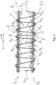
- FIG. 3 A further embodiment of a fabric and a method of weaving fabric, respectively, is shown in Fig. 3 .
- this embodiment again, there are transition zones Z in the two fabrics F 1 , F 2 where a change of the inclination of the piles P provided in each one of the two fabrics F 1 , F 2 occurs.
- the transition zones Z of Fig. 1 in which not only the direction of inclination of the piles P but additionally the pile forming pile warp yarn is changed, in the transition zones Z of the embodiment shown in Fig. 3 only the direction of inclination of the piles P is changed.
- a weft receiving opening O in which both end weft yarns E 1 , E 2 are used for interlacing the pile forming pile warp yarn PY 1 .
- Both end weft yarns E 1 , E 2 of these weft receiving openings O are on the back side BS relative to the associated tension warp yarns T and relative to the dead pile warp yarns bound into the respective fabrics F 1 , F 2 (four in the top fabric F 1 and three in the bottom fabric F 2 ).
- this a weaving structure in each one of the two fabrics F 1 , F 2 , in association with the respective weft receiving openings O, two piles P, each pile P comprising two pile legs PL 1 , PL 2 are provided. This leads to an increased pile density in the area of this transition zones Z and avoids the occurrence of a pile gap in these transition zones Z.
- the immediately adjacent end weft yarn E 2 of at least one weft receiving opening O positioned immediately adjacent to the weft receiving opening O of the transition zone Z and not used for interlacing with a pile-forming pile warp yarn may be positioned at the back side BS relative to the tension warp yarn T and the dead pile warp yarn PY 2 bound into this fabric, such as to be on the same level as the immediately adjacent end weft yarn E 1 of the transition zone Z.
- the immediately adjacent end weft yarn of at least one immediately adjacent weft receiving opening O may be positioned on the pile side PS relative to the dead pile warp yarns and on the back side BS relative to the tension warp yarns T, such that only the tension warp yarns T are used as weft separating warp yarns between this immediately adjacent end weft yarn and the intermediate weft yarn of the weft receiving opening O and in these areas.
Landscapes
- Engineering & Computer Science (AREA)
- Textile Engineering (AREA)
- Woven Fabrics (AREA)
Claims (15)
- Tissu, en particulier tapis, ayant un effet d'ombre, comprenant :- un tissu de dossier (BF) ayant des fils de chaîne de liage (B1, B2) se croisant de manière répétée pour fournir des ouvertures de réception de trame (O), des fils de chaîne de tension (T) s'étendant essentiellement dans une direction de chaîne (WA), et des fils de trame (E1, I, E2) s'étendant essentiellement dans une direction de trame à travers les ouvertures de réception de trame (O),- des fils de chaîne de poil (PY1, PY2, PY3, PY4) entrelacés avec des fils de trame (E1, E2) du tissu de dossier (BF) pour fournir des poils (P) sortant du tissu de dossier (BF) sur un côté poil (PS),dans lequel, dans au moins une ouverture de réception de trame (O), de préférence la majorité des ouvertures de réception de trame (O), de manière la plus préférée chaque ouverture de réception de trame (O), chacun des deux fils de trame (E1, E2) positionnés immédiatement adjacents aux deux croisements (C1, C2) des fils de chaîne de liage (B1, B2) définissant cette ouverture de réception de trame (O) dans la direction de chaîne (WA), fournit un fil de trame d'extrémité (E1, E2) positionné sur une face arrière (BS) par rapport à au moins un fil de chaîne de séparation de trame (T, PY1, PY2, PY2, PY3, PY4) s'étendant dans le tissu de dossier (BF) essentiellement dans la direction de chaîne (WA), et au moins un fil de trame intermédiaire (I) positionné adjacent à un tel fil de trame d'extrémité (E1, E2) dans la direction de chaîne (WA) est positionné du côté poil (PS) par rapport audit au moins un fil de chaîne de séparation de trame (T, PY1, PY2, PY2, PY3, PY4), dans lequel, pour fournir un poil (P) en association avec cette ouverture de réception de trame (O), un fil de chaîne de poil (PY1, PY2, PY3) est entrelacé avec un fil de trame d'extrémité (E1, E2) de cette ouverture de réception de trame (O) de manière à sortir du tissu de dossier (BF) entre ce fil de trame d'extrémité (E1, E2) et un fil de trame intermédiaire (I) de cette ouverture de réception de trame (O).
- Tissu selon la revendication 1, dans lequel au moins un poil (P) comprend deux jambes de poil (PL1, PL2), l'une des jambes de poil (PL1, PL2) s'étendant hors du tissu de dossier (BF) entre le fil de trame d'extrémité (E1, E2) avec lequel un fil de chaîne de poil (PY1, PY2, PY3) est entrelacé et le fil de trame intermédiaire (I), et l'autre jambe de poil (PL1, PL2) s'étendant hors du tissu de dossier (BF) entre le fil de trame d'extrémité (E1, E2) avec lequel un fil de chaîne de poil (PY1, PY2, PY3) est entrelacé et un fil de trame d'extrémité (E1, E2) d'une ouverture de réception de trame (O) immédiatement adjacente, et/ou dans lequel au moins un poil (P) comprend une jambe de poil unique (PLs) s'étendant hors du tissu de dossier (BF) entre le fil de trame d'extrémité (E1, E2) avec lequel un fil de chaîne de poil (PY1, PY2, PY3) est entrelacé et le fil de trame intermédiaire (I), et/ou dans lequel au moins un poil (P) comprend une jambe de poil unique (PLs) s'étendant hors du tissu de dossier (BF) entre le fil de trame d'extrémité (E1, E2) avec lequel un fil de chaîne de poil (PY1, PY2, PY3) est entrelacé et un fil de trame d'extrémité (E1, E2) d'une ouverture de réception de trame (O) immédiatement adjacente.
- Tissu selon la revendication 1 ou 2, dans lequel, en association avec au moins une ouverture de réception de trame (O), un poil (P) est fourni en entrelaçant un fil de chaîne de poil (PY1, PY2, PY3) avec un fil de trame d'extrémité (E1, E2) de cette ouverture de réception de trame (O) positionnée immédiatement adjacente au croisement (C1) des fils de chaîne de liage (B1, B2) définissant cette ouverture de réception de trame (O) dans une première orientation (OW1) de la direction de chaîne (WA) et, en association avec au moins une autre ouverture de réception de trame (O), un poil (P) est prévu en entrelaçant un fil de chaîne de poil (P1, P2, P3) avec un fil de trame d'extrémité (E1, E2) de cette ouverture de réception de trame (O) placée immédiatement adjacent au croisement (C2) des fils de chaîne de liage (B1, B2) définissant cette ouverture de réception de trame (O) dans une deuxième orientation (OW2) de la direction de chaîne (WA), et/ou dans lequel en association avec au moins une ouverture de réception de trame (O), de préférence la majorité des ouvertures de réception de trame (O), de manière la plus préférée chaque ouverture de réception de trame (O), une seule poil (P) est prévue.
- Tissu selon l'une des revendications 1 à 3, dans lequel des fils de chaîne de poils (PY1, PY2, PY3, PY4) non utilisés pour former des poils (P) sont liés dans le tissu de dossier (BF) de manière à s'étendre essentiellement dans la direction de chaîne (WA) en tant que fils de chaîne de poils morts, et dans lequel au moins un, de préférence, chaque fil de trame intermédiaire (I) d'au moins une ouverture de réception de trame (O) est séparé des deux fils de trame d'extrémité (E1, E2) de cette ouverture de réception de trame (O) par au moins un fil de chaîne de tension (T) et au moins un, de préférence tous les fils de chaîne de poil mort s'étendant dans la zone de cette ouverture de réception de trame (O).
- Tissu selon l'une des revendications 1 à 4, dans lequel des fils de chaîne de poil (PY1, PY2, PY3, PY4) non utilisés pour former des poils (P) sont liés dans le tissu de dossier (BF) de manière à s'étendre essentiellement dans la direction de chaîne (WA) en tant que fils de chaîne de poil morts, et dans lequel au moins un, de préférence chaque fil de trame intermédiaire (I) d'au moins une ouverture de réception de trame (O) est séparé d'un premier des deux fils de trame d'extrémité (E1, E2) de cette ouverture de réception de trame (O) que par au moins un fil de chaîne de tension (T) et est séparé du deuxième des deux fils de trame d'extrémité (E1, E2) de cette ouverture de réception de trame (O) par au moins un fil de chaîne de tension (T) et au moins un, de préférence tous les fils de chaîne de poil mort s'étendant dans la zone de cette ouverture de réception de trame (O).
- Tissu selon la revendication 5, dans lequel, en association avec cette ouverture de réception de trame (O), un poil (P) est formé en entrelaçant un fil de chaîne de poil (PY2, PY3) avec le deuxième des deux fils de trame d'extrémité (E1, E2) de cette ouverture de réception de trame (O), et/ou dans lequel le premier des deux fils de trame d'extrémité (E1, E2) de cette ouverture de réception de trame (O) est disposé sur le côté poil (PS) par rapport aux fils de chaîne de poil morts s'étendant dans la zone de cette ouverture de réception de trame (O) et le deuxième des deux fils de trame d'extrémité (E1, E2) de cette ouverture de réception de trame (O) est disposé sur le côté arrière par rapport aux fils de chaîne de poil morts s'étendant dans la zone de cette ouverture de réception de trame (O).
- Tissu selon l'une des revendications 1 à 6,
dans lequel, à travers au moins une ouverture de réception de trame (O), de préférence la majorité des ouvertures de réception de trame (O), de manière la plus préférée chaque ouverture de réception de trame (O), deux fils de trame (E1, E2) fournissant les deux fils de trame d'extrémité (E1, E2) et un fil de trame intermédiaire (I) s'étendent essentiellement dans la direction de la trame,
et/ou dans lequel trois fils de trame (E1, I, E2) s'étendent à travers au moins une ouverture de réception de trame (O), de préférence la majorité des ouvertures de réception de trame (O), de manière la plus préférée chaque ouverture de réception de trame (O), et/ou
dans lequel une pluralité de systèmes de fils de chaîne sont prévus, se succédant dans la direction de la trame, au moins un système de fils de chaîne, de préférence la majorité des systèmes de fils de chaîne, de de manière la plus préférée chaque système de fils de chaîne, comprenant deux fils de chaîne de liage (B1, B2) se croisant, au moins un fil de chaîne de tension (T), et au moins un, de préférence une pluralité de fils de chaîne de poil (PY1), PY2, PY3, PY1), dans lequel, dans les systèmes de fils de chaîne de poil, les poils (P) sont fournis par les fils de chaîne de poil (PY1, PY2, PY3) d'un système de fils de chaîne de poil respectif en entrelaçant ces fils de chaîne de poil (PY1, PY2, PYs) avec des fils de trame (E1, E2) s'étendant à travers les ouvertures de réception de trame (O) fournies par les fils de chaîne de liage (B1, B2) du même système de fils de chaîne de poils, de préférence de telle sorte que, au moyen des fils de chaîne de poils (PY1, PY2, PY3, PY4) de chacun des systèmes de fils de chaîne, une rangée de poils s'étendant essentiellement dans la direction de chaîne (WA) soit prévue. - Tissu selon l'une des revendications 1 à 7,
dans lequel, dans au moins une ouverture de réception de trame (O), de préférence dans la majorité de ces ouvertures de réception de trame (O), de manière la plus préférée dans chaque ouverture de réception de trame (O), les deux fils de trame (E1, E2) positionnés immédiatement adjacents aux deux croisements (C1, C2) des fils de chaîne de liage (B1, B2) définissant cette ouverture de réception de trame (O) ne sont pas séparés par un fil de chaîne de tension (T),
et/ou
dans laquelle, dans la majeure partie du tissu (F1, F2), de préférence dans tout le tissu (F1, F2), l'armure de base du tissu de dossier (BF) prévue par les fils de chaîne de liage (B1, B2), les fils de chaîne de tension (T) et les fils de trame (E1, I, E2) est le même, et/ou les croisements (C1, C2) des fils de chaîne de liage (B1, B2) définissant les ouvertures de réception de trame (O) dans les deux orientations (OW1, OW2) de la direction de chaîne (WA) sont situés à la même position dans la direction de chaîne (WA). - Procédé de tissage d'un tissu, en particulier d'un tapis, présentant un effet d'ombre, dans lequel, pour le tissage d'un tissu de dossier (BF), des fils de chaîne de liage (B1, B2) sont prévus qui se croisent pour prévoir des ouvertures de réception de trame (O), de sorte que chaque ouverture de réception de trame (O) est définie dans la direction de chaîne (WA) par deux croisements (C1, C2) de fils de chaîne de liage (B1, B2), dans lequel des fils de chaîne de tension (T) sont prévus, s'étendant essentiellement dans la direction de chaîne (WA) et en association avec au moins une ouverture de réception de trame (O), de préférence la majorité des ouvertures de réception de trame (O), de manière particulièrement préférée chaque ouverture de réception de trame (O), des fils de trame (E1, I, E2) sont prévus, s'étendant à travers cette ouverture de réception de trame (O) essentiellement dans la direction de trame, de sorte que deux fils de trame (E1, E2) positionnés immédiatement adjacents aux deux croisements (C1, C2) définissant cette ouverture de réception de trame (O) dans la direction de chaîne (WA) sont prévus comme fils de trame d'extrémité (E1, E2) positionnés sur une face arrière (BS) par rapport à au moins un fil de chaîne de séparation de trame (T, PY1, PY2, PY3, PY4) et au moins un fil de trame intermédiaire (I) placé essentiellement entre les deux fils de trame d'extrémité (E1, E2) dans la direction de chaîne (WA) est placé sur un côté poil (PS) par rapport audit au moins un fil de chaîne de séparation de trame (T, PY1, PY2, PY3, PY4), dans lequel, en association avec cette ouverture de réception de trame (O), un poil (P) est généré en entrelaçant un fil de chaîne de poil (PY1, PY2, PY3) avec un des fils de trame d'extrémité (E1, E2) de cette ouverture de réception de trame (O) de manière à sortir du tissu de dossier (BF) du côté poil (PS) entre ce fil de trame d'extrémité (E1, E2) et un fil de trame intermédiaire (I) de cette ouverture de réception de trame (O).
- Procédé selon la revendication 9,
dans laquelle les fils de chaîne de poil (PY1, PY2, PY3, PY4) non utilisés pour former des poils (P) sont liés dans le tissu de dossier (BF) de manière à s'étendre essentiellement dans la direction de chaîne (WA) en tant que fils de chaîne de poil morts, et dans laquelle au moins un, de préférence, chaque fil de trame intermédiaire (I) d'au moins une ouverture de réception de trame (O) est séparé des deux fils de trame d'extrémité (E1, E2) de cette ouverture de réception de trame (O) par au moins un fil de chaîne de tension (T) et au moins un, de préférence tous les fils de poil mort s'étendant dans la zone de cette ouverture de réception de trame (O),
et/ou
dans laquelle les fils de chaîne de poil (PY1, PY2, PYs, PY4) non utilisés pour former des poils (P) sont liés dans le tissu de dossier (BF) de manière à s'étendre essentiellement dans la direction de chaîne (WA) en tant que fils de chaîne de poil morts, et dans laquelle au moins un, de préférence chaque fil de trame intermédiaire (I) d'au moins une ouverture de réception de trame (O) est séparé d'un premier des deux fils de trame d'extrémité (E1, E2) de cette ouverture de réception de trame (O) que par au moins un fil de chaîne de tension (T) et est séparé du deuxième des deux fils de trame d'extrémité (E1, E2) de cette ouverture de réception de trame (O) par au moins un fil de chaîne de tension (T) et au moins un, de préférence tous les fils de poil morts s'étendant dans la zone de cette ouverture de réception de trame (O), de préférence dans lequel, en association avec cette ouverture de réception de trame (O), un poil (P) est formé en entrelaçant un fil de chaîne de poil (PY2, PY3) avec le deuxième des deux fils de trame d'extrémité (E1, E2) de cette ouverture de réception de trame (O), et/ou de préférence dans lequel le premier des deux fils de trame d'extrémité (E1, E2) de cette ouverture de réception de trame (O) est disposé sur le côté poil (PS) par rapport aux fils de chaîne de poil morts s'étendant dans la zone de cette ouverture de réception de trame (O) et le deuxième des deux fils de trame d'extrémité (E1, E2) de cette ouverture de réception de trame (O) est disposé sur le côté arrière par rapport aux fils de chaîne de poil morts s'étendant dans la zone de cette ouverture de réception de trame (O). - Procédé selon l'une des revendications 9 ou 10, dans lequel, en association avec chaque tissu (F1, F2) à tisser, une pluralité de systèmes de fils de chaîne est prévue se succédant dans la direction de trame, au moins un système de fils de chaîne, de préférence la majorité des systèmes de fils de chaîne, plus préférablement chaque système de fils de chaîne, comprenant deux fils de chaîne de liage (B1, B2) se croisant, au moins un fil de chaîne de tension (T), et au moins un, de préférence plusieurs fils de chaîne de poil (PY1, PY2, PY3, PY4), dans lequel, dans les systèmes de fils de chaîne de poil, les poils (P) sont prévus par les fils de chaîne de poil (PY1, PY2), PY3) d'un système de fils de chaîne de poil respectif en entrelaçant ces fils de chaîne de poil (PY1, PY2, PY3) avec des fils de trame (E1, E2) s'étendant à travers les ouvertures de réception de trame (O) fournies par les fils de chaîne de liage (B1, B2) du même système de fils de chaîne de poil, de préférence de telle sorte qu'au moyen des fils de chaîne de poil (PY1, PY2, PY3, PY4) de chacun des systèmes de fils de chaîne, une rangée de poils (P) s'étendant essentiellement dans la direction de chaîne (WA) est prévue, de préférence dans laquelle en association avec au moins une, de préférence chaque dent de peigne d'une machine à tisser, au moins un système de fils de chaîne est prévu.
- Procédé selon l'une des revendications 9 à 11, dans lequel le procédé est un procédé de tissage face à face pour tisser simultanément deux tissus (F1, F2).
- Procédé selon la revendication 12 et la revendication 11, dans lequel au moins un, de préférence chaque système de fils de chaîne comprend les fils de chaîne (B1, B2, T, PY1, PY2, PY2,, PY4) pour les deux tissus (F1, F2) à tisser.
- Procédé selon la revendication 13, dans lequel, en association avec au moins un système de fils de chaîne, les croisements (C1, C2) des fils de chaîne de liage (B1, B2) de l'un des deux tissus (F1, F2) à tisser sont décalés par rapport aux croisements (C1, C2) des fils de chaîne de liage (B1, B2) de l'autre des tissus (F1, F2) à tisser dans la direction de chaîne (WA).
- Procédé selon l'une des revendications 9 à 14, dans lequel, dans au moins un tissu (F1, F2), les croisements (C1, C2) des fils de chaîne de liage (B1, B2) définissant les ouvertures de réception de trame (O) dans les deux orientations (OW1, OW2) de la direction de chaîne (WA) sont situés à la même position dans la direction de chaîne (WA).
Applications Claiming Priority (2)
| Application Number | Priority Date | Filing Date | Title |
|---|---|---|---|
| EP16151396.5A EP3192909A1 (fr) | 2016-01-15 | 2016-01-15 | Tissu, notamment une moquette et procédé de tissage d'un tissu |
| PCT/EP2017/050170 WO2017121673A1 (fr) | 2016-01-15 | 2017-01-05 | Tissu, en particulier tapis, et procédé de tissage de tissu |
Publications (2)
| Publication Number | Publication Date |
|---|---|
| EP3402917A1 EP3402917A1 (fr) | 2018-11-21 |
| EP3402917B1 true EP3402917B1 (fr) | 2021-03-17 |
Family
ID=55168170
Family Applications (2)
| Application Number | Title | Priority Date | Filing Date |
|---|---|---|---|
| EP16151396.5A Withdrawn EP3192909A1 (fr) | 2016-01-15 | 2016-01-15 | Tissu, notamment une moquette et procédé de tissage d'un tissu |
| EP17700901.6A Active EP3402917B1 (fr) | 2016-01-15 | 2017-01-05 | Tissu, notamment une moquette et procédé de tissage d'un tissu |
Family Applications Before (1)
| Application Number | Title | Priority Date | Filing Date |
|---|---|---|---|
| EP16151396.5A Withdrawn EP3192909A1 (fr) | 2016-01-15 | 2016-01-15 | Tissu, notamment une moquette et procédé de tissage d'un tissu |
Country Status (4)
| Country | Link |
|---|---|
| US (1) | US11028507B2 (fr) |
| EP (2) | EP3192909A1 (fr) |
| CN (1) | CN108541280B (fr) |
| WO (1) | WO2017121673A1 (fr) |
Families Citing this family (7)
| Publication number | Priority date | Publication date | Assignee | Title |
|---|---|---|---|---|
| BE1021026B1 (nl) * | 2013-01-09 | 2015-01-27 | Nv Michel Van De Wiele | Tapijt met een schaduweffect en werkwijze voor het weven van een tapijtweefsel met een schaduweffect. |
| EP3339486B1 (fr) * | 2016-12-21 | 2021-06-23 | Vandewiele NV | Tissu et procédé de tissage d'un tissu, en particulier une moquette |
| EP3702500B1 (fr) * | 2019-02-26 | 2022-04-06 | STÄUBLI BAYREUTH GmbH | Procédé de tissage de tissus à poils et tissu à poils tissé à l'aide d'un tel procédé |
| GB2585818B (en) * | 2019-05-02 | 2022-05-11 | Don & Low Ltd | Improvements in and relating to woven products |
| BE1027386B1 (nl) * | 2019-06-20 | 2021-01-27 | Vandewiele Nv | Weefmethode met regeling of sturing van de garenspanning in kettingdraden en weefmachine voor het produceren van een weefsel volgens deze weefmethode |
| CN110241505B (zh) * | 2019-06-27 | 2020-11-10 | 阜南华翔羊毛衫有限公司 | 一面阴影提花割绒一面拉毛磨毛的丝绒织物及其织造方法 |
| CN113668121B (zh) * | 2021-08-19 | 2023-01-24 | 江苏盛泰克纺织印染有限公司 | 一种稀密提花丝绒和仿烂花提花丝绒的联合织造方法 |
Family Cites Families (5)
| Publication number | Priority date | Publication date | Assignee | Title |
|---|---|---|---|---|
| TR201808546T4 (tr) * | 2011-09-06 | 2018-07-23 | Staeubli Bayreuth Gmbh | Halı dokuma yöntemi ve böyle bir yöntemle dokunmuş halı. |
| WO2013041938A2 (fr) * | 2011-09-22 | 2013-03-28 | Nv Michel Van De Wiele | Procédé permettant de tisser un tissu à poils |
| BE1021026B1 (nl) | 2013-01-09 | 2015-01-27 | Nv Michel Van De Wiele | Tapijt met een schaduweffect en werkwijze voor het weven van een tapijtweefsel met een schaduweffect. |
| BE1022393B1 (nl) * | 2013-01-10 | 2016-03-21 | Nv Michel Van De Wiele | Werkwijze voor het weven van poolweefsels en werkwijze voor het daarvoor uitrusten van een weefmachine |
| EP2894244B1 (fr) * | 2014-01-09 | 2018-11-28 | STÄUBLI BAYREUTH GmbH | Procédé de fabrication d'un tissu à poils et tissu à poils avec des zones de poils de l'ombre |
-
2016
- 2016-01-15 EP EP16151396.5A patent/EP3192909A1/fr not_active Withdrawn
-
2017
- 2017-01-05 WO PCT/EP2017/050170 patent/WO2017121673A1/fr active Application Filing
- 2017-01-05 EP EP17700901.6A patent/EP3402917B1/fr active Active
- 2017-01-05 CN CN201780005149.0A patent/CN108541280B/zh active Active
- 2017-01-05 US US16/064,527 patent/US11028507B2/en active Active
Non-Patent Citations (1)
| Title |
|---|
| None * |
Also Published As
| Publication number | Publication date |
|---|---|
| WO2017121673A1 (fr) | 2017-07-20 |
| EP3402917A1 (fr) | 2018-11-21 |
| CN108541280A (zh) | 2018-09-14 |
| CN108541280B (zh) | 2021-01-12 |
| US20190010636A1 (en) | 2019-01-10 |
| EP3192909A1 (fr) | 2017-07-19 |
| US11028507B2 (en) | 2021-06-08 |
Similar Documents
| Publication | Publication Date | Title |
|---|---|---|
| EP3402917B1 (fr) | Tissu, notamment une moquette et procédé de tissage d'un tissu | |
| EP0628649B1 (fr) | Procédé pour la fabrication du velours face contre face | |
| US6817383B2 (en) | Weaving machine and method for weaving fabrics with pile loops | |
| US7086424B2 (en) | Method and system for weaving fabrics with two useable sides | |
| US7287552B2 (en) | Process for weaving fabrics and shaggy fabrics | |
| EP1900861B1 (fr) | Procédé de tissage d'une étoffe et étoffe tissée selon ce procédé | |
| EP2758573B1 (fr) | Procédé permettant de tisser un tissu à poils | |
| US10655252B2 (en) | Fabric and method of weaving a fabric, in particular a carpet | |
| EP2943603B1 (fr) | Moquette ayant un effet d'ombre et procédé de tissage d'un tissu de tapis ayant un effet d'ombre | |
| EP1666652A3 (fr) | Procédé de tissage de tissus face contre face, tissu tissé selon ce procédé et métier à tisser double face pour mettre en oeuvre ledit procédé | |
| EP2894244A1 (fr) | Procédé de fabrication d'un tissu à poils et tissu à poils avec de zones de poils de l'ombre | |
| US20150354107A1 (en) | Method for weaving pile fabrics and for configuring a weaving loom therefor | |
| EP1152076B1 (fr) | Procédé pour la fabrication face contre face de tissus à poils et tissus tissés selon ce procédé | |
| EP1398403B1 (fr) | Procédé pour tisser un tissu à poils | |
| EP0919652B1 (fr) | Procédé pour la fabrication d'un tissu à poil avec des fils de poil de chaíne grossière | |
| EP0922799B1 (fr) | Procédé pour tisser un tissu à poil avec une haute densité de poil | |
| US2613695A (en) | Distortion weave fabric structure | |
| US2306390A (en) | Pile fabric and method of making same | |
| US2306405A (en) | Pile fabric and method of making same | |
| US873744A (en) | Pile fabric. | |
| EP0887449A1 (fr) | Velours ombré jacquard, dispositif et procédé pour la fabrication d'un tel velours ombré jacquard |
Legal Events
| Date | Code | Title | Description |
|---|---|---|---|
| STAA | Information on the status of an ep patent application or granted ep patent |
Free format text: STATUS: UNKNOWN |
|
| STAA | Information on the status of an ep patent application or granted ep patent |
Free format text: STATUS: THE INTERNATIONAL PUBLICATION HAS BEEN MADE |
|
| PUAI | Public reference made under article 153(3) epc to a published international application that has entered the european phase |
Free format text: ORIGINAL CODE: 0009012 |
|
| STAA | Information on the status of an ep patent application or granted ep patent |
Free format text: STATUS: REQUEST FOR EXAMINATION WAS MADE |
|
| 17P | Request for examination filed |
Effective date: 20180730 |
|
| AK | Designated contracting states |
Kind code of ref document: A1 Designated state(s): AL AT BE BG CH CY CZ DE DK EE ES FI FR GB GR HR HU IE IS IT LI LT LU LV MC MK MT NL NO PL PT RO RS SE SI SK SM TR |
|
| AX | Request for extension of the european patent |
Extension state: BA ME |
|
| DAV | Request for validation of the european patent (deleted) | ||
| DAX | Request for extension of the european patent (deleted) | ||
| RAP1 | Party data changed (applicant data changed or rights of an application transferred) |
Owner name: VANDEWIELE NV |
|
| GRAP | Despatch of communication of intention to grant a patent |
Free format text: ORIGINAL CODE: EPIDOSNIGR1 |
|
| STAA | Information on the status of an ep patent application or granted ep patent |
Free format text: STATUS: GRANT OF PATENT IS INTENDED |
|
| GRAJ | Information related to disapproval of communication of intention to grant by the applicant or resumption of examination proceedings by the epo deleted |
Free format text: ORIGINAL CODE: EPIDOSDIGR1 |
|
| STAA | Information on the status of an ep patent application or granted ep patent |
Free format text: STATUS: REQUEST FOR EXAMINATION WAS MADE |
|
| INTG | Intention to grant announced |
Effective date: 20200507 |
|
| STAA | Information on the status of an ep patent application or granted ep patent |
Free format text: STATUS: EXAMINATION IS IN PROGRESS |
|
| INTC | Intention to grant announced (deleted) | ||
| 17Q | First examination report despatched |
Effective date: 20200612 |
|
| GRAP | Despatch of communication of intention to grant a patent |
Free format text: ORIGINAL CODE: EPIDOSNIGR1 |
|
| STAA | Information on the status of an ep patent application or granted ep patent |
Free format text: STATUS: GRANT OF PATENT IS INTENDED |
|
| INTG | Intention to grant announced |
Effective date: 20201123 |
|
| GRAS | Grant fee paid |
Free format text: ORIGINAL CODE: EPIDOSNIGR3 |
|
| GRAA | (expected) grant |
Free format text: ORIGINAL CODE: 0009210 |
|
| STAA | Information on the status of an ep patent application or granted ep patent |
Free format text: STATUS: THE PATENT HAS BEEN GRANTED |
|
| AK | Designated contracting states |
Kind code of ref document: B1 Designated state(s): AL AT BE BG CH CY CZ DE DK EE ES FI FR GB GR HR HU IE IS IT LI LT LU LV MC MK MT NL NO PL PT RO RS SE SI SK SM TR |
|
| REG | Reference to a national code |
Ref country code: GB Ref legal event code: FG4D |
|
| REG | Reference to a national code |
Ref country code: CH Ref legal event code: EP |
|
| REG | Reference to a national code |
Ref country code: DE Ref legal event code: R096 Ref document number: 602017034697 Country of ref document: DE |
|
| REG | Reference to a national code |
Ref country code: IE Ref legal event code: FG4D |
|
| REG | Reference to a national code |
Ref country code: AT Ref legal event code: REF Ref document number: 1372333 Country of ref document: AT Kind code of ref document: T Effective date: 20210415 |
|
| REG | Reference to a national code |
Ref country code: LT Ref legal event code: MG9D |
|
| PG25 | Lapsed in a contracting state [announced via postgrant information from national office to epo] |
Ref country code: HR Free format text: LAPSE BECAUSE OF FAILURE TO SUBMIT A TRANSLATION OF THE DESCRIPTION OR TO PAY THE FEE WITHIN THE PRESCRIBED TIME-LIMIT Effective date: 20210317 Ref country code: FI Free format text: LAPSE BECAUSE OF FAILURE TO SUBMIT A TRANSLATION OF THE DESCRIPTION OR TO PAY THE FEE WITHIN THE PRESCRIBED TIME-LIMIT Effective date: 20210317 Ref country code: GR Free format text: LAPSE BECAUSE OF FAILURE TO SUBMIT A TRANSLATION OF THE DESCRIPTION OR TO PAY THE FEE WITHIN THE PRESCRIBED TIME-LIMIT Effective date: 20210618 Ref country code: NO Free format text: LAPSE BECAUSE OF FAILURE TO SUBMIT A TRANSLATION OF THE DESCRIPTION OR TO PAY THE FEE WITHIN THE PRESCRIBED TIME-LIMIT Effective date: 20210617 Ref country code: BG Free format text: LAPSE BECAUSE OF FAILURE TO SUBMIT A TRANSLATION OF THE DESCRIPTION OR TO PAY THE FEE WITHIN THE PRESCRIBED TIME-LIMIT Effective date: 20210617 |
|
| REG | Reference to a national code |
Ref country code: AT Ref legal event code: MK05 Ref document number: 1372333 Country of ref document: AT Kind code of ref document: T Effective date: 20210317 |
|
| REG | Reference to a national code |
Ref country code: NL Ref legal event code: MP Effective date: 20210317 |
|
| PG25 | Lapsed in a contracting state [announced via postgrant information from national office to epo] |
Ref country code: LV Free format text: LAPSE BECAUSE OF FAILURE TO SUBMIT A TRANSLATION OF THE DESCRIPTION OR TO PAY THE FEE WITHIN THE PRESCRIBED TIME-LIMIT Effective date: 20210317 Ref country code: RS Free format text: LAPSE BECAUSE OF FAILURE TO SUBMIT A TRANSLATION OF THE DESCRIPTION OR TO PAY THE FEE WITHIN THE PRESCRIBED TIME-LIMIT Effective date: 20210317 Ref country code: SE Free format text: LAPSE BECAUSE OF FAILURE TO SUBMIT A TRANSLATION OF THE DESCRIPTION OR TO PAY THE FEE WITHIN THE PRESCRIBED TIME-LIMIT Effective date: 20210317 |
|
| PG25 | Lapsed in a contracting state [announced via postgrant information from national office to epo] |
Ref country code: NL Free format text: LAPSE BECAUSE OF FAILURE TO SUBMIT A TRANSLATION OF THE DESCRIPTION OR TO PAY THE FEE WITHIN THE PRESCRIBED TIME-LIMIT Effective date: 20210317 |
|
| PG25 | Lapsed in a contracting state [announced via postgrant information from national office to epo] |
Ref country code: LT Free format text: LAPSE BECAUSE OF FAILURE TO SUBMIT A TRANSLATION OF THE DESCRIPTION OR TO PAY THE FEE WITHIN THE PRESCRIBED TIME-LIMIT Effective date: 20210317 Ref country code: CZ Free format text: LAPSE BECAUSE OF FAILURE TO SUBMIT A TRANSLATION OF THE DESCRIPTION OR TO PAY THE FEE WITHIN THE PRESCRIBED TIME-LIMIT Effective date: 20210317 Ref country code: EE Free format text: LAPSE BECAUSE OF FAILURE TO SUBMIT A TRANSLATION OF THE DESCRIPTION OR TO PAY THE FEE WITHIN THE PRESCRIBED TIME-LIMIT Effective date: 20210317 Ref country code: AT Free format text: LAPSE BECAUSE OF FAILURE TO SUBMIT A TRANSLATION OF THE DESCRIPTION OR TO PAY THE FEE WITHIN THE PRESCRIBED TIME-LIMIT Effective date: 20210317 Ref country code: SM Free format text: LAPSE BECAUSE OF FAILURE TO SUBMIT A TRANSLATION OF THE DESCRIPTION OR TO PAY THE FEE WITHIN THE PRESCRIBED TIME-LIMIT Effective date: 20210317 |
|
| PG25 | Lapsed in a contracting state [announced via postgrant information from national office to epo] |
Ref country code: SK Free format text: LAPSE BECAUSE OF FAILURE TO SUBMIT A TRANSLATION OF THE DESCRIPTION OR TO PAY THE FEE WITHIN THE PRESCRIBED TIME-LIMIT Effective date: 20210317 Ref country code: RO Free format text: LAPSE BECAUSE OF FAILURE TO SUBMIT A TRANSLATION OF THE DESCRIPTION OR TO PAY THE FEE WITHIN THE PRESCRIBED TIME-LIMIT Effective date: 20210317 Ref country code: PL Free format text: LAPSE BECAUSE OF FAILURE TO SUBMIT A TRANSLATION OF THE DESCRIPTION OR TO PAY THE FEE WITHIN THE PRESCRIBED TIME-LIMIT Effective date: 20210317 Ref country code: PT Free format text: LAPSE BECAUSE OF FAILURE TO SUBMIT A TRANSLATION OF THE DESCRIPTION OR TO PAY THE FEE WITHIN THE PRESCRIBED TIME-LIMIT Effective date: 20210719 Ref country code: IS Free format text: LAPSE BECAUSE OF FAILURE TO SUBMIT A TRANSLATION OF THE DESCRIPTION OR TO PAY THE FEE WITHIN THE PRESCRIBED TIME-LIMIT Effective date: 20210717 |
|
| REG | Reference to a national code |
Ref country code: DE Ref legal event code: R097 Ref document number: 602017034697 Country of ref document: DE |
|
| PLBE | No opposition filed within time limit |
Free format text: ORIGINAL CODE: 0009261 |
|
| STAA | Information on the status of an ep patent application or granted ep patent |
Free format text: STATUS: NO OPPOSITION FILED WITHIN TIME LIMIT |
|
| PG25 | Lapsed in a contracting state [announced via postgrant information from national office to epo] |
Ref country code: DK Free format text: LAPSE BECAUSE OF FAILURE TO SUBMIT A TRANSLATION OF THE DESCRIPTION OR TO PAY THE FEE WITHIN THE PRESCRIBED TIME-LIMIT Effective date: 20210317 Ref country code: AL Free format text: LAPSE BECAUSE OF FAILURE TO SUBMIT A TRANSLATION OF THE DESCRIPTION OR TO PAY THE FEE WITHIN THE PRESCRIBED TIME-LIMIT Effective date: 20210317 Ref country code: ES Free format text: LAPSE BECAUSE OF FAILURE TO SUBMIT A TRANSLATION OF THE DESCRIPTION OR TO PAY THE FEE WITHIN THE PRESCRIBED TIME-LIMIT Effective date: 20210317 |
|
| 26N | No opposition filed |
Effective date: 20211220 |
|
| PG25 | Lapsed in a contracting state [announced via postgrant information from national office to epo] |
Ref country code: SI Free format text: LAPSE BECAUSE OF FAILURE TO SUBMIT A TRANSLATION OF THE DESCRIPTION OR TO PAY THE FEE WITHIN THE PRESCRIBED TIME-LIMIT Effective date: 20210317 |
|
| PG25 | Lapsed in a contracting state [announced via postgrant information from national office to epo] |
Ref country code: IT Free format text: LAPSE BECAUSE OF FAILURE TO SUBMIT A TRANSLATION OF THE DESCRIPTION OR TO PAY THE FEE WITHIN THE PRESCRIBED TIME-LIMIT Effective date: 20210317 |
|
| PG25 | Lapsed in a contracting state [announced via postgrant information from national office to epo] |
Ref country code: IS Free format text: LAPSE BECAUSE OF FAILURE TO SUBMIT A TRANSLATION OF THE DESCRIPTION OR TO PAY THE FEE WITHIN THE PRESCRIBED TIME-LIMIT Effective date: 20210717 |
|
| PG25 | Lapsed in a contracting state [announced via postgrant information from national office to epo] |
Ref country code: MC Free format text: LAPSE BECAUSE OF FAILURE TO SUBMIT A TRANSLATION OF THE DESCRIPTION OR TO PAY THE FEE WITHIN THE PRESCRIBED TIME-LIMIT Effective date: 20210317 |
|
| REG | Reference to a national code |
Ref country code: CH Ref legal event code: PL |
|
| GBPC | Gb: european patent ceased through non-payment of renewal fee |
Effective date: 20220105 |
|
| PG25 | Lapsed in a contracting state [announced via postgrant information from national office to epo] |
Ref country code: LU Free format text: LAPSE BECAUSE OF NON-PAYMENT OF DUE FEES Effective date: 20220105 Ref country code: GB Free format text: LAPSE BECAUSE OF NON-PAYMENT OF DUE FEES Effective date: 20220105 |
|
| PG25 | Lapsed in a contracting state [announced via postgrant information from national office to epo] |
Ref country code: FR Free format text: LAPSE BECAUSE OF NON-PAYMENT OF DUE FEES Effective date: 20220131 |
|
| PG25 | Lapsed in a contracting state [announced via postgrant information from national office to epo] |
Ref country code: LI Free format text: LAPSE BECAUSE OF NON-PAYMENT OF DUE FEES Effective date: 20220131 Ref country code: CH Free format text: LAPSE BECAUSE OF NON-PAYMENT OF DUE FEES Effective date: 20220131 |
|
| PG25 | Lapsed in a contracting state [announced via postgrant information from national office to epo] |
Ref country code: IE Free format text: LAPSE BECAUSE OF NON-PAYMENT OF DUE FEES Effective date: 20220105 |
|
| PG25 | Lapsed in a contracting state [announced via postgrant information from national office to epo] |
Ref country code: HU Free format text: LAPSE BECAUSE OF FAILURE TO SUBMIT A TRANSLATION OF THE DESCRIPTION OR TO PAY THE FEE WITHIN THE PRESCRIBED TIME-LIMIT; INVALID AB INITIO Effective date: 20170105 |
|
| PG25 | Lapsed in a contracting state [announced via postgrant information from national office to epo] |
Ref country code: MK Free format text: LAPSE BECAUSE OF FAILURE TO SUBMIT A TRANSLATION OF THE DESCRIPTION OR TO PAY THE FEE WITHIN THE PRESCRIBED TIME-LIMIT Effective date: 20210317 Ref country code: CY Free format text: LAPSE BECAUSE OF FAILURE TO SUBMIT A TRANSLATION OF THE DESCRIPTION OR TO PAY THE FEE WITHIN THE PRESCRIBED TIME-LIMIT Effective date: 20210317 |
|
| PGFP | Annual fee paid to national office [announced via postgrant information from national office to epo] |
Ref country code: DE Payment date: 20240119 Year of fee payment: 8 |
|
| PGFP | Annual fee paid to national office [announced via postgrant information from national office to epo] |
Ref country code: TR Payment date: 20240104 Year of fee payment: 8 Ref country code: BE Payment date: 20240119 Year of fee payment: 8 |