EP3165486B1 - System und verfahren zur verarbeitung eines flexiblen substrats - Google Patents
System und verfahren zur verarbeitung eines flexiblen substrats Download PDFInfo
- Publication number
- EP3165486B1 EP3165486B1 EP16195726.1A EP16195726A EP3165486B1 EP 3165486 B1 EP3165486 B1 EP 3165486B1 EP 16195726 A EP16195726 A EP 16195726A EP 3165486 B1 EP3165486 B1 EP 3165486B1
- Authority
- EP
- European Patent Office
- Prior art keywords
- web
- indexer
- flexible substrate
- tensioner
- vacuum plate
- Prior art date
- Legal status (The legal status is an assumption and is not a legal conclusion. Google has not performed a legal analysis and makes no representation as to the accuracy of the status listed.)
- Active
Links
Images


Classifications
-
- B—PERFORMING OPERATIONS; TRANSPORTING
- B65—CONVEYING; PACKING; STORING; HANDLING THIN OR FILAMENTARY MATERIAL
- B65H—HANDLING THIN OR FILAMENTARY MATERIAL, e.g. SHEETS, WEBS, CABLES
- B65H23/00—Registering, tensioning, smoothing or guiding webs
- B65H23/04—Registering, tensioning, smoothing or guiding webs longitudinally
- B65H23/24—Registering, tensioning, smoothing or guiding webs longitudinally by fluid action, e.g. to retard the running web
- B65H23/245—Suction retarders
-
- H—ELECTRICITY
- H10—SEMICONDUCTOR DEVICES; ELECTRIC SOLID-STATE DEVICES NOT OTHERWISE PROVIDED FOR
- H10P—GENERIC PROCESSES OR APPARATUS FOR THE MANUFACTURE OR TREATMENT OF DEVICES COVERED BY CLASS H10
- H10P72/00—Handling or holding of wafers, substrates or devices during manufacture or treatment thereof
- H10P72/30—Handling or holding of wafers, substrates or devices during manufacture or treatment thereof for conveying, e.g. between different workstations
- H10P72/33—Handling or holding of wafers, substrates or devices during manufacture or treatment thereof for conveying, e.g. between different workstations into and out of processing chamber
- H10P72/3314—Continuous loading and unloading into and out of a processing chamber, e.g. transporting belts within processing chambers
-
- B—PERFORMING OPERATIONS; TRANSPORTING
- B65—CONVEYING; PACKING; STORING; HANDLING THIN OR FILAMENTARY MATERIAL
- B65G—TRANSPORT OR STORAGE DEVICES, e.g. CONVEYORS FOR LOADING OR TIPPING, SHOP CONVEYOR SYSTEMS OR PNEUMATIC TUBE CONVEYORS
- B65G47/00—Article or material-handling devices associated with conveyors; Methods employing such devices
- B65G47/74—Feeding, transfer, or discharging devices of particular kinds or types
- B65G47/90—Devices for picking-up and depositing articles or materials
-
- B—PERFORMING OPERATIONS; TRANSPORTING
- B65—CONVEYING; PACKING; STORING; HANDLING THIN OR FILAMENTARY MATERIAL
- B65H—HANDLING THIN OR FILAMENTARY MATERIAL, e.g. SHEETS, WEBS, CABLES
- B65H20/00—Advancing webs
- B65H20/12—Advancing webs by suction roller
-
- H—ELECTRICITY
- H05—ELECTRIC TECHNIQUES NOT OTHERWISE PROVIDED FOR
- H05K—PRINTED CIRCUITS; CASINGS OR CONSTRUCTIONAL DETAILS OF ELECTRIC APPARATUS; MANUFACTURE OF ASSEMBLAGES OF ELECTRICAL COMPONENTS
- H05K1/00—Printed circuits
- H05K1/02—Details
- H05K1/03—Use of materials for the substrate
- H05K1/038—Textiles
-
- H—ELECTRICITY
- H10—SEMICONDUCTOR DEVICES; ELECTRIC SOLID-STATE DEVICES NOT OTHERWISE PROVIDED FOR
- H10P—GENERIC PROCESSES OR APPARATUS FOR THE MANUFACTURE OR TREATMENT OF DEVICES COVERED BY CLASS H10
- H10P72/00—Handling or holding of wafers, substrates or devices during manufacture or treatment thereof
- H10P72/04—Apparatus for manufacture or treatment
- H10P72/0442—Apparatus for placing on an insulating substrate, e.g. tape
-
- H—ELECTRICITY
- H10—SEMICONDUCTOR DEVICES; ELECTRIC SOLID-STATE DEVICES NOT OTHERWISE PROVIDED FOR
- H10P—GENERIC PROCESSES OR APPARATUS FOR THE MANUFACTURE OR TREATMENT OF DEVICES COVERED BY CLASS H10
- H10P72/00—Handling or holding of wafers, substrates or devices during manufacture or treatment thereof
- H10P72/30—Handling or holding of wafers, substrates or devices during manufacture or treatment thereof for conveying, e.g. between different workstations
- H10P72/33—Handling or holding of wafers, substrates or devices during manufacture or treatment thereof for conveying, e.g. between different workstations into and out of processing chamber
- H10P72/3302—Mechanical parts of transfer devices
-
- B—PERFORMING OPERATIONS; TRANSPORTING
- B65—CONVEYING; PACKING; STORING; HANDLING THIN OR FILAMENTARY MATERIAL
- B65H—HANDLING THIN OR FILAMENTARY MATERIAL, e.g. SHEETS, WEBS, CABLES
- B65H2301/00—Handling processes for sheets or webs
- B65H2301/40—Type of handling process
- B65H2301/44—Moving, forwarding, guiding material
- B65H2301/443—Moving, forwarding, guiding material by acting on surface of handled material
- B65H2301/4432—Moving, forwarding, guiding material by acting on surface of handled material by means having an operating surface contacting only one face of the material, e.g. roller
- B65H2301/44324—Rollers
-
- B—PERFORMING OPERATIONS; TRANSPORTING
- B65—CONVEYING; PACKING; STORING; HANDLING THIN OR FILAMENTARY MATERIAL
- B65H—HANDLING THIN OR FILAMENTARY MATERIAL, e.g. SHEETS, WEBS, CABLES
- B65H2301/00—Handling processes for sheets or webs
- B65H2301/40—Type of handling process
- B65H2301/44—Moving, forwarding, guiding material
- B65H2301/443—Moving, forwarding, guiding material by acting on surface of handled material
- B65H2301/4433—Moving, forwarding, guiding material by acting on surface of handled material by means holding the material
- B65H2301/44336—Moving, forwarding, guiding material by acting on surface of handled material by means holding the material using suction forces
-
- B—PERFORMING OPERATIONS; TRANSPORTING
- B65—CONVEYING; PACKING; STORING; HANDLING THIN OR FILAMENTARY MATERIAL
- B65H—HANDLING THIN OR FILAMENTARY MATERIAL, e.g. SHEETS, WEBS, CABLES
- B65H2301/00—Handling processes for sheets or webs
- B65H2301/40—Type of handling process
- B65H2301/44—Moving, forwarding, guiding material
- B65H2301/449—Features of movement or transforming movement of handled material
- B65H2301/4491—Features of movement or transforming movement of handled material transforming movement from continuous to intermittent or vice versa
-
- B—PERFORMING OPERATIONS; TRANSPORTING
- B65—CONVEYING; PACKING; STORING; HANDLING THIN OR FILAMENTARY MATERIAL
- B65H—HANDLING THIN OR FILAMENTARY MATERIAL, e.g. SHEETS, WEBS, CABLES
- B65H2406/00—Means using fluid
- B65H2406/30—Suction means
- B65H2406/35—Other elements with suction surface, e.g. plate or wall
- B65H2406/351—Other elements with suction surface, e.g. plate or wall facing the surface of the handled material
-
- B—PERFORMING OPERATIONS; TRANSPORTING
- B65—CONVEYING; PACKING; STORING; HANDLING THIN OR FILAMENTARY MATERIAL
- B65H—HANDLING THIN OR FILAMENTARY MATERIAL, e.g. SHEETS, WEBS, CABLES
- B65H2701/00—Handled material; Storage means
- B65H2701/10—Handled articles or webs
- B65H2701/17—Nature of material
- B65H2701/173—Metal
-
- B—PERFORMING OPERATIONS; TRANSPORTING
- B65—CONVEYING; PACKING; STORING; HANDLING THIN OR FILAMENTARY MATERIAL
- B65H—HANDLING THIN OR FILAMENTARY MATERIAL, e.g. SHEETS, WEBS, CABLES
- B65H2701/00—Handled material; Storage means
- B65H2701/10—Handled articles or webs
- B65H2701/17—Nature of material
- B65H2701/175—Plastic
-
- B—PERFORMING OPERATIONS; TRANSPORTING
- B65—CONVEYING; PACKING; STORING; HANDLING THIN OR FILAMENTARY MATERIAL
- B65H—HANDLING THIN OR FILAMENTARY MATERIAL, e.g. SHEETS, WEBS, CABLES
- B65H2701/00—Handled material; Storage means
- B65H2701/10—Handled articles or webs
- B65H2701/19—Specific article or web
- B65H2701/1942—Web supporting regularly spaced non-adhesive articles
Definitions
- Certain types of electronic products may be manufactured on flexible substrates, such paper or plastic substrates (e.g., polymer textile carriers), which is sometimes referred to as a "web".
- a web allows the electronic products to be manufactured in high volume and in an efficient manner.
- the web is transported continuously through a web processing system.
- the web may need to intermittently stopped within the web processing system to perform some processing operation on the web.
- accurate positioning of the web for repeated execution of the processing operation when the web is temporarily stopped is very important.
- varying friction between the web and components of the processing system presents a significant challenge in achieving high precision accuracy of the web position within in the processing system.
- US 6 003 420 A describes a die set in an apparatus for manufacturing filmstrips having a variable length and a variable number of perforations from a long strip of continuous film, wherein said die set device is provided with a plurality of punch holders aligned adjacent to one another in a film transporting direction. At least one of the punch holders are selectively actuated to make a designated number of equally spaced perforations at a time.
- a film length adjusting device is provided for adjusting the length of the continuous film extending between the die set device and a cutter in accordance with a unit length which is determined for each variable length of the filmstrip, such that the cutter and the punch holder or punch holders are actuated in synchronism with each other while the continuous film stops after each transport by the unit length.
- a pair of feed rollers are disposed between the cutter and a suction drum for transporting the film toward the cutter.
- the feed rollers have diameters less than that of the suction drum.
- a side-printer is arranged to record data on the film at a peripheral position of a larger one of the feed rollers.
- GB 2 067 524 A describes an apparatus for braking travelling strips without surface scratching. To apply a braking force to only one face of a travelling metallic strip with the least possible surface scratching, it is passed over a suction box whose perforated wall is covered by a permeable layer.
- a processing system and a method for processing a flexible substrate use a tensioner with a vacuum plate that can be moved along a transport direction of the flexible substrate with an indexer that intermittently moves the flexible substrate for processing.
- the tensioner and the indexer are controlled so that a relative speed between the indexer and the vacuum plate of the tensioner is maintained above a predefined threshold under all working conditions, even when the flexible substrate is stopped.
- a processing system in accordance with an embodiment of the invention comprises a tensioner with a vacuum plate configured to provide tension on a flexible substrate as the flexible substrate is transported over the vacuum plate along a transport direction, the vacuum plate being configured to be moved along the transport direction, an indexer configured to intermittently move the flexible substrate for processing, and a controller configured to control the tensioner and the indexer so that a relative speed between the indexer and the vacuum plate of the tensioner is maintained above a predefined threshold under all working conditions, even when the flexible substrate is stopped.
- the controller is configured to move the vacuum plate of the tensioner in the opposite direction of the transport direction when the indexer is stopped.
- the controller is configured to move the vacuum plate of the tensioner so that the relative speed between the indexer and the vacuum plate of the tensioner is maintained in a linear region of the Stribeck curve.
- the processing system further comprises a processing device that performs a process on the flexible substrate on the indexer when the indexer is stopped.
- the processing device is a pick-and-place device that places a device onto the flexible substrate.
- the indexer includes a drum with vacuum holes to move the web as the drum is rotated.
- the indexer is a linear indexer.
- the tensioner has a curved surface that can be moved in a rotational direction.
- the flexible substrate is made of paper, plastic or metal.
- a processing system in accordance with another embodiment of the invention comprises a web tensioner with a vacuum plate configured to provide tension on a web as the web is transported over the vacuum plate along a transport direction, the vacuum plate being configured to be moved along the transport direction, a web indexer including a drum with vacuum holes, the drum being configured to be intermittently rotated to move the web, a processing device configured to process the web on the drum of the web indexer, and a controller configured to control the web tensioner and the web indexer so that a relative speed between the drum of the web indexer and the vacuum plate of the web tensioner is maintained above a predefined threshold under all working conditions, even when the web is stopped.
- the controller is configured to move the vacuum plate in the opposite direction of the transport direction when the drum of the web indexer is stopped.
- the controller is configured to move the vacuum plate of the web tensioner so that the relative speed between the drum of the web indexer and the vacuum plate of the web tensioner is maintained in a linear region of the Stribeck curve.
- the processing device is a pick-and-place device that places a device onto the web on the drum of the web indexer.
- a method for processing a flexible substrate in accordance with an embodiment of the invention comprises supplying a flexible substrate to an indexer through a tensioner with a vacuum plate so that the flexible substrate is transported over the vacuum plate, intermittently moving the flexible substrate along a transport direction for processing, and moving the vacuum plate of the tensioner along the transport direction so that a relative speed between the indexer and the vacuum plate of the tensioner is maintained above a predefined threshold under all working conditions, even when the flexible substrate is stopped.
- the moving of the vacuum plate of the tensioner includes moving the vacuum plate of the tensioner in the opposite direction of the transport direction when the indexer is stopped.
- the moving of the vacuum plate of the tensioner includes moving the vacuum plate of the tensioner so that the relative speed between the indexer and the vacuum plate of the tensioner is maintained in a linear region of the Stribeck curve.
- the method further comprises performing a process on the flexible substrate on the indexer when the indexer is stopped.
- the processing of the flexible substrate includes placing a device onto the flexible substrate.
- the intermittently moving of the flexible substrate at the indexer includes rotating a drum with vacuum holes of the indexer to move the flexible substrate.
- the intermittently moving of the flexible substrate at the indexer includes linearly moving the flexible substrate at the indexer.
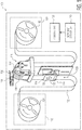
- Fig. 1 shows a processing system 100 in accordance with an embodiment of the invention is shown.
- the processing system operates on a flexible substrate 102, which is referred to herein as a "web".
- the flexible substrate can be made of any flexible material.
- the flexible substrate may be, but not limited to, a long strip of paper, a long strip of polymer textile carrier or a long strip of flexible metal.
- the web may include electrical structures or traces formed thereon.
- the processing system is designed to transport and guide the web through the processing system so that one or more processes can be performed on the web, such as pick-and-place process of integrated circuit (IC) chips or other electronic components onto the web.
- the processing system operates to transport the web through the processing system in a high precision manner.
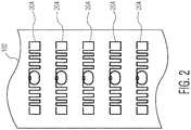
- FIG. 2 An example of the web 102, which can be used in the processing system 100, is depicted in Fig. 2 .
- the web includes a number of electrical structures 204 that are separated from each other by some distance. These electrical structures can be any type of flexible electronics. These electrical structures are fabricated on the web prior to the web being processed by the processing system. In some applications, a device may need to be placed on each of the electrical structures at a precise location. Thus, accurately transporting the web through the processing system so that the device can be precisely placed at the designated placement location on the web is very important.
- the processing system 100 includes a de-reeling unit 112, a web tensioner 114, a web indexer 116, a processing device 118, a reeling unit 120, and a controller 122.
- various support structures for the different components of the processing system are not shown in order to not obscure the inventive features of the system.
- the web 102 is being processed by the processing system, and thus, is transported and guided through the various components of the processing system.
- the web is transported from the de-reeling unit to the reeling unit through the web tensioner and the web indexer so that the web can be processed by the processing device at the web indexer.
- the web tensioner, the web indexer and the processing device can be viewed as being a web processing set.
- the processing system includes only one web processing set. However, in other embodiments, the processing system may include one or more additional web processing sets.
- the de-reeling unit 112 of the processing system 100 operates to de-reel a roll of the web 102, which is typically rolled on a terminal reel 124, to be processed.
- the de-reeling unit supplies the web to the next module (i.e., the web tensioner 114) without tension.
- the de-reeling unit includes mechanisms to hold and rotate the terminal reel 124 so that the web can be de-reeled. These mechanisms can be commonly found in conventional processing systems, and thus, are not illustrated or described in detail herein.
- the web tensioner 114 of the processing system 100 operates to provide tension on the web 102 so that the movement of the web through the system, in particular, at the web indexer 116, can be controlled with high precision.
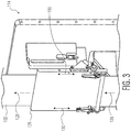
- the web tensioner 114 includes a vacuum plate or table 126 that pulls or attracts the web using suction or negative gas pressure, as best shown in Fig. 3 .
- the suction on the web from the vacuum plate provides tension on the web, while still allowing the web to move or travel along a transport direction, which is indicated by arrows 128.
- the vacuum plate includes a number of holes, which are connected to a vacuum pump (not show) that provides the suction.
- the vacuum plate is designed to move forward and reverse in the transport direction, as indicated by double arrows 130.
- a controlled movement of the vacuum plate allows the web to be transported and guided with high precision.
- the vacuum plate is connected to one or more drive mechanisms, such as motors, that can displace the vacuum plate with desired velocity in the desired direction.
- the vacuum plate is further designed to move in the lateral direction with respect to the transport direction, i.e., in the direction orthogonal to the transport direction, as indicated by a double arrow 132 (See Fig. 1 ), in order to control the lateral movement of the web. With sufficient tension on the web in the transport direction, the web will not significantly shift in the lateral direction when the web is indexed or moved by the web indexer 116. In the embodiment shown in Figs.
- the web tensioner includes the plate that has a flat surface for interfacing with the web.
- the web tensioner may include a component with a curved surface for interface with the web, such as a drum.
- the curved surface of the web tensioner may be moved in a rotational direction, rather than in a linear direction.
- the web tensioner may be implemented as one or more rollers that provide tension on the web.
- the web indexer 116 of the processing system 100 operates to index or precisely transport the web 102 so that a specific location or spot of the web is displaced to a desired processing location.
- the web can be moved so that a designated location on one of the electrical structures 204 (see Fig. 2 ) on the web is aligned with a particular position so that a device can be placed at the designated location.
- the web indexer includes a circular drum 134 with multiple vacuum holes that pulls or attracts the web using suction or negative gas pressure, similar to the web tensioner 114. The suction on the web from the drum allows the drum to transport or move the web in the transport direction when the drum is rotated in the transport direction.
- the vacuum holes of the drum are connected to a vacuum pump (not show), which can be the same vacuum pump used for the web tensioner, that provides the suction.
- the vacuum of the drum may differ from the vacuum of the vacuum plate 126 of the web tensioner.
- the vacuum of the vacuum plate may be less than the vacuum of the drum. The reason for difference is that the drum vacuum only needs to fix the web on the drum, and therefore, can be maximized.
- the vacuum plate vacuum is used to create a certain hold force to create tension in the web when the web moves over the vacuum, and therefore, can be less than the drum vacuum.
- the drum is connected to one or more drive mechanisms, such as motors, that can rotate the drum in a controlled manner.
- the drum is further designed to move in the lateral direction with respect to the transport direction, i.e., in the direction orthogonal to the transport direction, as indicated by a double arrow 138 in Fig. 1 , in order to control the lateral movement of the web.
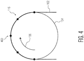
- the web indexer 116 is able to index the web 102 (i.e., to transport the web over the pitch distance) by rotating the drum 134, which is illustrated in Fig. 4 .
- the drum of the web indexer is rotated in the clockwise direction that corresponds to the transport direction (indicated by an arrow 136), which also moves the web in the same direction.
- the web is transported by the rotation of the drum so that a specific spot of the web, e.g., a die placement location on one of the antenna structures 204 (see Fig. 2 ), is moved to a process position 400 at a particular moment in time.
- the web is transported or moved intermittently by the drum so that the desired areas of the web can be sequentially stopped at the process position for processing.
- the web may be stopped and started several times per second. In order for the desired areas of the web to be stopped at the process position at the right moments in time, the web must be accurately transported by the drum.
- Accurate transport of the web 102 can be obtained by accurate position measurement of the web and accurate control of the web indexer 116.
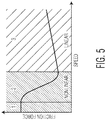
- Accurate control of the web indexer position can be obtained by means of high bandwidth control loops and accurate feed forward. Feed forward compensates for known forces such as acceleration forces and frictional forces. However, frictional forces are difficult to compensate because the frictional force depends on speed in a quite complex fashion, as defined by the Stribeck curve, which is shown in Fig. 5 .
- the Stribeck curve shows that frictional force at low speeds (zones 1 and 2 in Fig. 5 ) is quite nonlinear and non-reproducible. Above a certain speed, however, the frictional force is quite linear with speed (zone 3 in Fig. 5 ).
- the frictional force that needs to be compensated by a feed forward depends on the relative speed between the speed of the web tensioner 114 and the rotational speed of the web indexer 116 (i.e., the speed of the drum surface). If the web tensioner uses a static vacuum plate, which is easiest to implement, the relative speed between the web tensioner and the web indexer would vary from zero to the maximum transport speed, as illustrated in Fig. 6 . In this case, the frictional force would have a typical Stribeck behavior, which is difficult to compensate due to the non-repetitive behavior around zero speed, i.e., when the web indexer is stopped. That is, the web will initially stick to the web tensioner with high friction and then will switch to a lower friction after the web achieves a certain velocity with respect to the web tensioner.
- the vacuum plate 126 of the web tensioner 114 is moved in the reversed transport direction with specific speed profile so that the relative speed between the web tensioner and the web indexer 116 can be kept at nonzero speeds. If the relative speed is nonzero above a certain threshold, the frictional force can be compensated with a simple predictable linear compensation yielding a better position accuracy in the end. That is, if the relative speed threshold is maintained in the linear zone of the Stribeck curve, i.e., zone 3 of the Stribeck curve, the compensation for the frictional force is much easier.
- the vacuum plate of the web tensioner moves in the opposite direction of the transport direction to keep a constant velocity between the web and the vacuum plate. So when the drum of the web indexer starts to move again, the frictional force at the web tensioner is still in the linear zone of the Stribeck curve. If the frictional force at the web tensioner is maintained in the Stribeck linear zone when the drum of the web indexer is stopped, then accurate web position is much easier to achieve for the next cycle (i.e., when the web is stopped again) by the processing system 100.
- the processing system 100 includes a setpoint generator 140 that creates a motion profile for the vacuum plate 126 of the web tensioner 114, which is synchronous with the movements of the web indexer 116 (i.e., the rotational movement of the drum 134), in order to control the relative speed between the web tensioner and the web indexer.
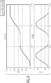
- the motion profile is created such that the average speed of the web tensioner is zero and the speed of the web tensioner is lower than zero, i.e., moving in the negative transport direction, if the web indexer speed is zero.
- the speed of the web tensioner refers to the speed of the vacuum plate 126 of the web tensioner and the speed of the web indexer refers to the rotational speed of the drum 134 of the web indexer.
- the motion profile is created such that the relative speed between the web indexer and the web tensioner is maintained above a certain threshold so that the frictional force between the web tensioner and the web is in the linear zone of the Stribeck curve, i.e., zone 3 of the Stribeck curve.
- Fig. 7 shows the relative speed between the web indexer and the web tensioner, which is maintained above the desired threshold speed, as well as the position and speed of the web indexer and the web tensioner.
- the processing device 118 of the processing system 100 operates to process a device on the web 102 on the drum 134 of the web indexer 116.
- the processing device 118 processes the device to the process position 400 while the desired spot of web is moved to that process position, as shown in Fig. 4 .
- the processing device is a pick-and-place device that loads electronic components, such as IC chips, onto the desired spots of the web.
- the processing device may be any processing device that can perform any process on the web at or near the web indexer.
- the reeling unit 120 of the processing system 100 operates to reel the web 102, which has been processed by the processing device 118, onto another terminal reel 142. Similar to the de-reeling unit 112, the reeling unit includes mechanisms (not shown) to hold and rotate the terminal reel 142 so that the processed web can be reeled onto the terminal reel 142. After the entire web has been processed and reeled onto the terminal reel 142, the terminal reel with the processed web can be removed from the processing system.
- the controller 122 of the processing system 100 operates to control the various components of the system, including the de-reeling unit 112, the web tensioner 114, the web indexer 116, the processing device 118 and the reeling unit 120.
- the controller controls the speed or rotation of the web indexer, as well as the speed of the web tensioner.
- the controller controls the relative speed between the web indexer and the web tensioner using the motion profile created by the setpoint generator 140.
- the setpoint generator may be a computer program running on the controller. In other embodiments, the setpoint generator may be implemented in any combination of software, hardware and firmware.
- the controller may include one or more processors and/or one or more microcontrollers to process information and control the various components of the processing system.
- the web indexer 116 may be a different type of a web indexing device, such as a linear web indexer.
- Fig. 8 shows one example of a linear web indexer 800 that can be used in the processing system 100 instead of the web indexer 116.
- the linear web indexer includes a support structure 802 and a pair of rollers 804.
- the support structure 802 provides support for the web 102 as the web is transported linearly along the transport direction, as indicated by the arrow 128.
- the rollers 804 operate to intermittently move the web along the transport direction so that the web can be processed when each desired spot or area of the web is moved to a process position, as indicated by the dotted arrow 806.
- Other types of web indexing device that can accurately transport the web may be used in the processing system.
- Fig. 9 is a process flow diagram of a method for processing a flexible substrate, such as the web 102, in accordance with an embodiment of the invention.
- a flexible substrate is supplied to an indexer, such as the web indexer 116, through a web tensioner with a vacuum plate, such as the web tensioner 114, so that the flexible substrate is transported over the vacuum plate.
- the flexible substrate is intermittently moved along a transport direction for processing.
- the vacuum plate of the tensioner is moved along the transport direction so that a relative speed between the indexer and the vacuum plate of the tensioner is maintained above a predefined threshold under all working conditions, even when the flexible substrate, e.g., the web, is stopped.
Landscapes
- Engineering & Computer Science (AREA)
- Mechanical Engineering (AREA)
- Textile Engineering (AREA)
- Microelectronics & Electronic Packaging (AREA)
- Controlling Rewinding, Feeding, Winding, Or Abnormalities Of Webs (AREA)
- Registering, Tensioning, Guiding Webs, And Rollers Therefor (AREA)
- Advancing Webs (AREA)
- Supply And Installment Of Electrical Components (AREA)
Claims (15)
- Verarbeitungssystem (100) mit:einer Spannvorrichtung (114) mit einer Unterdruckplatte (126), die dazu konfiguriert ist, eine Spannung an einem flexiblen Substrat (102) bereitzustellen, wenn das flexible Substrat (102) über der Unterdruckplatte (126) entlang einer Transportrichtung transportiert wird, wobei die Unterdruckplatte (126) dazu konfiguriert ist, entlang der Transportrichtung bewegt zu werden;einem Indizierer (116), der dazu konfiguriert ist, das flexible Substrat (102) für eine Verarbeitung intermittierend zu bewegen; undeiner Steuervorrichtung (122), die dazu konfiguriert ist, die Spannvorrichtung (114) und den Indizierer (116) so zu steuern, dass eine relative Geschwindigkeit zwischen dem Indizierer (116) und der Unterdruckplatte (126) der Spannvorrichtung (114) über einen vordefinierten Schwellwert unter allen Arbeitsbedingungen aufrecht erhalten wird, auch wenn das flexible Substrat (102) gestoppt wird.
- Verarbeitungssystem (100) gemäß Anspruch 1, wobei die Steuervorrichtung (122) dazu konfiguriert ist, die Unterdruckplatte (126) der Spannvorrichtung (114) in der entgegengesetzten Richtung der Transportrichtung zu bewegen, wenn der Indizierer (116) gestoppt wird.
- Verarbeitungssystem (100) gemäß Anspruch 1 oder 2, wobei die Steuervorrichtung (122) dazu konfiguriert ist, die Unterdruckplatte (126) der Spannvorrichtung (114) so zu bewegen, dass die relative Geschwindigkeit zwischen dem Indizierer (116) und der Unterdruckplatte (126) der Spannvorrichtung (114) in einem linearen Bereich der Stribeck-Kurve aufrecht erhalten wird.
- Verarbeitungssystem (100) gemäß einem der vorherigen Ansprüche, des Weiteren mit einer Verarbeitungsvorrichtung (118), die einen Prozess an dem flexiblen Substrat (102) an dem Indizierer (116) durchführt, wenn der Indizierer (116) gestoppt wird.
- Verarbeitungssystem (100) gemäß Anspruch 3, wobei die Verarbeitungsvorrichtung (118) eine Bestückvorrichtung ist, die eine Vorrichtung auf das flexible Substrat (102) platziert.
- Verarbeitungssystem (100) gemäß einem der vorherigen Ansprüche, wobei der Indizierer (116) eine Trommel (134) mit Unterdrucklöchern aufweist, um das flexible Substrat (102) zu bewegen, wenn die Trommel (134) gedreht wird.
- Verarbeitungssystem (100) gemäß einem der vorherigen Ansprüche, wobei der Indizierer (116) ein linearer Indizierer ist.
- Verarbeitungssystem (100) gemäß einem der vorherigen Ansprüche, wobei die Spannvorrichtung (114) eine gekrümmte Fläche hat, die in einer Drehrichtung bewegt werden kann.
- Verarbeitungssystem (100) gemäß einem der vorherigen Ansprüche, wobei das flexible Substrat (102) aus Papier, Kunststoff oder Metall besteht.
- Verfahren zum Verarbeiten eines flexiblen Substrats (102), wobei das Verfahren Folgendes aufweist:Zuführen eines flexiblen Substrats (102) zu einem Indizierer (116) durch eine Spannvorrichtung (114) mit einer Unterdruckplatte (126), so dass das flexible Substrat (102) über die Unterdruckplatte (126) transportiert wird;intermittierendes Bewegen des flexiblen Substrats (102) entlang einer Transportrichtung zur Verarbeitung; undBewegen der Unterdruckplatte (126) der Spannvorrichtung (114) entlang der Transportrichtung derart, dass eine relative Geschwindigkeit zwischen dem Indizierer (116) und der Unterdruckplatte (126) der Spannvorrichtung (114) über einen vordefinierten Schwellwert unter allen Arbeitsbedingungen aufrecht erhalten wird, auch wenn das flexible Substrat (102) gestoppt wird.
- Verfahren gemäß Anspruch 10, des Weiteren mit einem Durchführen eines Prozesses an dem flexiblen Substrat (102) an dem Indizierer (116), wenn der Indizierer gestoppt ist.
- Verfahren gemäß Anspruch 11, wobei die Verarbeitung des flexiblen Substrats (102) ein Platzieren einer Vorrichtung auf das flexible Substrat (102) aufweist.
- Verfahren gemäß einem der Ansprüche 10 bis 12, wobei das intermittierende Bewegen des flexiblen Substrats (102) an dem Indizierer (116) ein Drehen einer Trommel mit Unterdrucklöchern des Indizierers (116) aufweist, um das flexible Substrat (102) zu bewegen.
- Verfahren gemäß einem der Ansprüche 10 bis 13, wobei das intermittierende Bewegen des flexiblen Substrats (102) an dem Indizierer (116) ein lineares Bewegen des flexiblen Substrats (102) an dem Indizierer (116) aufweist.
- Verarbeitungssystem (100) gemäß einem der Ansprüche 1 bis 9, wobei das flexible Substrat (102) ein Gewebe ist.
Applications Claiming Priority (1)
| Application Number | Priority Date | Filing Date | Title |
|---|---|---|---|
| US14/935,185 US9994407B2 (en) | 2015-11-06 | 2015-11-06 | System and method for processing a flexible substrate |
Publications (2)
| Publication Number | Publication Date |
|---|---|
| EP3165486A1 EP3165486A1 (de) | 2017-05-10 |
| EP3165486B1 true EP3165486B1 (de) | 2019-09-11 |
Family
ID=57389180
Family Applications (1)
| Application Number | Title | Priority Date | Filing Date |
|---|---|---|---|
| EP16195726.1A Active EP3165486B1 (de) | 2015-11-06 | 2016-10-26 | System und verfahren zur verarbeitung eines flexiblen substrats |
Country Status (6)
| Country | Link |
|---|---|
| US (1) | US9994407B2 (de) |
| EP (1) | EP3165486B1 (de) |
| JP (1) | JP6835432B2 (de) |
| KR (1) | KR102632990B1 (de) |
| CN (1) | CN106684015B (de) |
| TW (1) | TWI708729B (de) |
Family Cites Families (25)
| Publication number | Priority date | Publication date | Assignee | Title |
|---|---|---|---|---|
| CH325428A (de) | 1957-06-25 | 1957-11-15 | Kg Zimmer S Erben | Vorrichtung zum zeitweisen Festhalten eines flächenförmigen Materials zur Ermöglichung eines schrittweisen Weitertransportes desselben |
| US3489325A (en) * | 1967-10-25 | 1970-01-13 | Borg Warner | Control system with multichamber vacuum unit for regulating lateral web alignment |
| DE2949902A1 (de) | 1979-12-12 | 1981-06-19 | Fa. Josef Fröhling, 5960 Olpe | Vorrichtung zum abbremsen laufenden bandmaterials |
| US4326656A (en) * | 1980-06-25 | 1982-04-27 | International Business Machines | Evacuated printing platen |
| JPS6371058A (ja) * | 1986-09-12 | 1988-03-31 | Mitsubishi Heavy Ind Ltd | 連続シ−トの間欠送り装置 |
| JPH09507666A (ja) | 1994-01-24 | 1997-08-05 | シーメンス ニクスドルフ インフオルマチオーンスジステーメ アクチエンゲゼルシヤフト | 帯状の記録担体を処理するための摩擦駆動装置を備えた印刷装置 |
| US6003420A (en) | 1994-04-26 | 1999-12-21 | Fuji Photo Film Co., Ltd. | Apparatus for manufacturing photographic filmstrips |
| DE29504553U1 (de) | 1995-03-17 | 1995-06-14 | Voith Sulzer Papiermaschinen GmbH, 89522 Heidenheim | Vorrichtung zum Stabilisieren einer Warenbahn |
| JP3336832B2 (ja) * | 1995-11-07 | 2002-10-21 | 松下電器産業株式会社 | アルミ電解コンデンサ用電極箔の一定張力発生装置 |
| JP2000235267A (ja) | 1999-02-15 | 2000-08-29 | Asahi Optical Co Ltd | 走査式描画装置 |
| CN1739186B (zh) | 2003-01-16 | 2010-10-13 | Nxp股份有限公司 | 芯片传送方法与设备 |
| TWI356658B (en) * | 2003-01-23 | 2012-01-11 | Toray Industries | Members for circuit board, method and device for m |
| US20050000842A1 (en) * | 2003-06-03 | 2005-01-06 | Lee Timmerman | Bundled printed sheets |
| CN100594757C (zh) * | 2004-03-31 | 2010-03-17 | 三菱电线工业株式会社 | 电路基板及其制造方法和采用该电路基板的接线箱 |
| EP1753977B1 (de) | 2004-05-28 | 2011-02-02 | Nxp B.V. | Chip-transfervorrichtung mit einrichtung zum ausgleich der schwerkraft |
| EP1721750A1 (de) | 2005-05-09 | 2006-11-15 | Agfa-Gevaert | Hilfsvorrichtung zur Halterung eines Mediums in einem schrittweisen Transportsystem eines digitalen Druckers |
| CN101379605B (zh) | 2006-02-10 | 2011-04-20 | Nxp股份有限公司 | 具有包括对准光学装置和目标的设备的光学仪器的半导体加工系统 |
| JP2009056570A (ja) * | 2007-09-03 | 2009-03-19 | Fuji Electric Systems Co Ltd | 長尺フィルムの型抜き加工方法および装置 |
| KR101250656B1 (ko) | 2009-01-19 | 2013-04-03 | 야마하 파인 테크 가부시키가이샤 | 소편 부재의 이동 탑재 정착 장치 |
| US8541163B2 (en) * | 2009-06-05 | 2013-09-24 | Nikon Corporation | Transporting method, transporting apparatus, exposure method, and exposure apparatus |
| EP2488429B1 (de) * | 2009-10-13 | 2019-05-08 | M-Solv Limited | Vorrichtung und verfahren zur verarbeitung von langen kontinuierlichen flexiblen substraten |
| JP5517155B2 (ja) * | 2010-02-15 | 2014-06-11 | アイセル株式会社 | 打抜装置 |
| KR20140050649A (ko) * | 2011-07-05 | 2014-04-29 | 어플라이드 머티어리얼스, 인코포레이티드 | 가요성 기판을 프로세싱하기 위한 방법 |
| ITMO20120155A1 (it) | 2012-06-15 | 2013-12-16 | Kemet Electronics Italia S R L | Metodo e apparato per lavorare materiale in nastro |
| CN203588979U (zh) * | 2013-11-07 | 2014-05-07 | 昆山工研院新型平板显示技术中心有限公司 | 柔性基板处理装置 |
-
2015
- 2015-11-06 US US14/935,185 patent/US9994407B2/en active Active
-
2016
- 2016-08-30 TW TW105127847A patent/TWI708729B/zh active
- 2016-09-23 JP JP2016185545A patent/JP6835432B2/ja active Active
- 2016-10-26 EP EP16195726.1A patent/EP3165486B1/de active Active
- 2016-11-02 CN CN201610968989.4A patent/CN106684015B/zh active Active
- 2016-11-03 KR KR1020160145786A patent/KR102632990B1/ko active Active
Non-Patent Citations (1)
| Title |
|---|
| None * |
Also Published As
| Publication number | Publication date |
|---|---|
| KR20170053582A (ko) | 2017-05-16 |
| TWI708729B (zh) | 2020-11-01 |
| EP3165486A1 (de) | 2017-05-10 |
| US20170129731A1 (en) | 2017-05-11 |
| CN106684015A (zh) | 2017-05-17 |
| CN106684015B (zh) | 2021-09-10 |
| KR102632990B1 (ko) | 2024-02-01 |
| JP6835432B2 (ja) | 2021-02-24 |
| TW201726531A (zh) | 2017-08-01 |
| JP2017088406A (ja) | 2017-05-25 |
| US9994407B2 (en) | 2018-06-12 |
Similar Documents
| Publication | Publication Date | Title |
|---|---|---|
| CN103998147B (zh) | 自动化涂片制造装置 | |
| KR101340160B1 (ko) | 반도체 웨이퍼의 보호 테이프 절단 방법 및 보호 테이프절단 장치 | |
| CN105752686A (zh) | 基板处理装置 | |
| JP6350453B2 (ja) | ウエブ搬送装置 | |
| CN108472932B (zh) | 将高度柔性基底结合到载体或与载体基体去结合的方法和设备 | |
| US10104784B2 (en) | Method for making an electronic product with flexible substrate | |
| JP6645457B2 (ja) | ウェブ加工装置 | |
| WO1996011494A1 (en) | Apparatus and method for bonding tape | |
| EP3115138B1 (de) | Unterdruckfolienstruktur | |
| US9994407B2 (en) | System and method for processing a flexible substrate | |
| TW201305036A (zh) | 捲對捲定位拉引系統 | |
| US4990080A (en) | Punch press for piercing green sheet with liner | |
| WO2016022104A1 (en) | Pre-treating separator to enable separator for pick and place operation | |
| JPH11240653A (ja) | スリット基材の巻取装置 | |
| CN211104420U (zh) | 载带张紧机构和自动冲切机 | |
| JP2016092060A (ja) | 部品供給装置、表面実装機、及び部品の供給方法 | |
| US7211164B2 (en) | Lamination apparatus for ceramic green sheet and lamination method | |
| CN102976133A (zh) | 卷对卷定位拉引系统 | |
| KR101871341B1 (ko) | 필름 자재 등속 이송장치 | |
| JP2002225157A (ja) | テープ断ち切り貼り付け装置 | |
| JP7340732B2 (ja) | 部品供給装置、部品実装装置、部品供給方法及び部品実装方法 | |
| KR20130143024A (ko) | 가요성 기판의 반송장치 및 표시 디바이스 또는 전자회로의 제조 시스템 | |
| JP2006066617A (ja) | 部品供給装置 | |
| JP6744678B1 (ja) | 基材搬送装置及び基材処理装置 | |
| JP2019085201A (ja) | 剥離装置 |
Legal Events
| Date | Code | Title | Description |
|---|---|---|---|
| PUAI | Public reference made under article 153(3) epc to a published international application that has entered the european phase |
Free format text: ORIGINAL CODE: 0009012 |
|
| STAA | Information on the status of an ep patent application or granted ep patent |
Free format text: STATUS: THE APPLICATION HAS BEEN PUBLISHED |
|
| AK | Designated contracting states |
Kind code of ref document: A1 Designated state(s): AL AT BE BG CH CY CZ DE DK EE ES FI FR GB GR HR HU IE IS IT LI LT LU LV MC MK MT NL NO PL PT RO RS SE SI SK SM TR |
|
| AX | Request for extension of the european patent |
Extension state: BA ME |
|
| STAA | Information on the status of an ep patent application or granted ep patent |
Free format text: STATUS: REQUEST FOR EXAMINATION WAS MADE |
|
| 17P | Request for examination filed |
Effective date: 20171110 |
|
| RBV | Designated contracting states (corrected) |
Designated state(s): AL AT BE BG CH CY CZ DE DK EE ES FI FR GB GR HR HU IE IS IT LI LT LU LV MC MK MT NL NO PL PT RO RS SE SI SK SM TR |
|
| GRAP | Despatch of communication of intention to grant a patent |
Free format text: ORIGINAL CODE: EPIDOSNIGR1 |
|
| STAA | Information on the status of an ep patent application or granted ep patent |
Free format text: STATUS: GRANT OF PATENT IS INTENDED |
|
| RIC1 | Information provided on ipc code assigned before grant |
Ipc: B65H 23/24 20060101AFI20190521BHEP |
|
| INTG | Intention to grant announced |
Effective date: 20190606 |
|
| GRAS | Grant fee paid |
Free format text: ORIGINAL CODE: EPIDOSNIGR3 |
|
| GRAA | (expected) grant |
Free format text: ORIGINAL CODE: 0009210 |
|
| STAA | Information on the status of an ep patent application or granted ep patent |
Free format text: STATUS: THE PATENT HAS BEEN GRANTED |
|
| AK | Designated contracting states |
Kind code of ref document: B1 Designated state(s): AL AT BE BG CH CY CZ DE DK EE ES FI FR GB GR HR HU IE IS IT LI LT LU LV MC MK MT NL NO PL PT RO RS SE SI SK SM TR |
|
| REG | Reference to a national code |
Ref country code: GB Ref legal event code: FG4D |
|
| REG | Reference to a national code |
Ref country code: CH Ref legal event code: EP |
|
| REG | Reference to a national code |
Ref country code: AT Ref legal event code: REF Ref document number: 1178208 Country of ref document: AT Kind code of ref document: T Effective date: 20190915 |
|
| REG | Reference to a national code |
Ref country code: DE Ref legal event code: R096 Ref document number: 602016020294 Country of ref document: DE Ref country code: IE Ref legal event code: FG4D |
|
| REG | Reference to a national code |
Ref country code: NL Ref legal event code: MP Effective date: 20190911 |
|
| REG | Reference to a national code |
Ref country code: LT Ref legal event code: MG4D |
|
| PG25 | Lapsed in a contracting state [announced via postgrant information from national office to epo] |
Ref country code: BG Free format text: LAPSE BECAUSE OF FAILURE TO SUBMIT A TRANSLATION OF THE DESCRIPTION OR TO PAY THE FEE WITHIN THE PRESCRIBED TIME-LIMIT Effective date: 20191211 Ref country code: NO Free format text: LAPSE BECAUSE OF FAILURE TO SUBMIT A TRANSLATION OF THE DESCRIPTION OR TO PAY THE FEE WITHIN THE PRESCRIBED TIME-LIMIT Effective date: 20191211 Ref country code: LT Free format text: LAPSE BECAUSE OF FAILURE TO SUBMIT A TRANSLATION OF THE DESCRIPTION OR TO PAY THE FEE WITHIN THE PRESCRIBED TIME-LIMIT Effective date: 20190911 Ref country code: HR Free format text: LAPSE BECAUSE OF FAILURE TO SUBMIT A TRANSLATION OF THE DESCRIPTION OR TO PAY THE FEE WITHIN THE PRESCRIBED TIME-LIMIT Effective date: 20190911 Ref country code: FI Free format text: LAPSE BECAUSE OF FAILURE TO SUBMIT A TRANSLATION OF THE DESCRIPTION OR TO PAY THE FEE WITHIN THE PRESCRIBED TIME-LIMIT Effective date: 20190911 Ref country code: SE Free format text: LAPSE BECAUSE OF FAILURE TO SUBMIT A TRANSLATION OF THE DESCRIPTION OR TO PAY THE FEE WITHIN THE PRESCRIBED TIME-LIMIT Effective date: 20190911 |
|
| PG25 | Lapsed in a contracting state [announced via postgrant information from national office to epo] |
Ref country code: AL Free format text: LAPSE BECAUSE OF FAILURE TO SUBMIT A TRANSLATION OF THE DESCRIPTION OR TO PAY THE FEE WITHIN THE PRESCRIBED TIME-LIMIT Effective date: 20190911 Ref country code: GR Free format text: LAPSE BECAUSE OF FAILURE TO SUBMIT A TRANSLATION OF THE DESCRIPTION OR TO PAY THE FEE WITHIN THE PRESCRIBED TIME-LIMIT Effective date: 20191212 Ref country code: RS Free format text: LAPSE BECAUSE OF FAILURE TO SUBMIT A TRANSLATION OF THE DESCRIPTION OR TO PAY THE FEE WITHIN THE PRESCRIBED TIME-LIMIT Effective date: 20190911 Ref country code: LV Free format text: LAPSE BECAUSE OF FAILURE TO SUBMIT A TRANSLATION OF THE DESCRIPTION OR TO PAY THE FEE WITHIN THE PRESCRIBED TIME-LIMIT Effective date: 20190911 Ref country code: ES Free format text: LAPSE BECAUSE OF FAILURE TO SUBMIT A TRANSLATION OF THE DESCRIPTION OR TO PAY THE FEE WITHIN THE PRESCRIBED TIME-LIMIT Effective date: 20190911 |
|
| REG | Reference to a national code |
Ref country code: AT Ref legal event code: MK05 Ref document number: 1178208 Country of ref document: AT Kind code of ref document: T Effective date: 20190911 |
|
| PG25 | Lapsed in a contracting state [announced via postgrant information from national office to epo] |
Ref country code: IT Free format text: LAPSE BECAUSE OF FAILURE TO SUBMIT A TRANSLATION OF THE DESCRIPTION OR TO PAY THE FEE WITHIN THE PRESCRIBED TIME-LIMIT Effective date: 20190911 Ref country code: RO Free format text: LAPSE BECAUSE OF FAILURE TO SUBMIT A TRANSLATION OF THE DESCRIPTION OR TO PAY THE FEE WITHIN THE PRESCRIBED TIME-LIMIT Effective date: 20190911 Ref country code: NL Free format text: LAPSE BECAUSE OF FAILURE TO SUBMIT A TRANSLATION OF THE DESCRIPTION OR TO PAY THE FEE WITHIN THE PRESCRIBED TIME-LIMIT Effective date: 20190911 Ref country code: AT Free format text: LAPSE BECAUSE OF FAILURE TO SUBMIT A TRANSLATION OF THE DESCRIPTION OR TO PAY THE FEE WITHIN THE PRESCRIBED TIME-LIMIT Effective date: 20190911 Ref country code: PL Free format text: LAPSE BECAUSE OF FAILURE TO SUBMIT A TRANSLATION OF THE DESCRIPTION OR TO PAY THE FEE WITHIN THE PRESCRIBED TIME-LIMIT Effective date: 20190911 Ref country code: EE Free format text: LAPSE BECAUSE OF FAILURE TO SUBMIT A TRANSLATION OF THE DESCRIPTION OR TO PAY THE FEE WITHIN THE PRESCRIBED TIME-LIMIT Effective date: 20190911 Ref country code: PT Free format text: LAPSE BECAUSE OF FAILURE TO SUBMIT A TRANSLATION OF THE DESCRIPTION OR TO PAY THE FEE WITHIN THE PRESCRIBED TIME-LIMIT Effective date: 20200113 |
|
| PG25 | Lapsed in a contracting state [announced via postgrant information from national office to epo] |
Ref country code: IS Free format text: LAPSE BECAUSE OF FAILURE TO SUBMIT A TRANSLATION OF THE DESCRIPTION OR TO PAY THE FEE WITHIN THE PRESCRIBED TIME-LIMIT Effective date: 20200224 Ref country code: CZ Free format text: LAPSE BECAUSE OF FAILURE TO SUBMIT A TRANSLATION OF THE DESCRIPTION OR TO PAY THE FEE WITHIN THE PRESCRIBED TIME-LIMIT Effective date: 20190911 Ref country code: SK Free format text: LAPSE BECAUSE OF FAILURE TO SUBMIT A TRANSLATION OF THE DESCRIPTION OR TO PAY THE FEE WITHIN THE PRESCRIBED TIME-LIMIT Effective date: 20190911 Ref country code: SM Free format text: LAPSE BECAUSE OF FAILURE TO SUBMIT A TRANSLATION OF THE DESCRIPTION OR TO PAY THE FEE WITHIN THE PRESCRIBED TIME-LIMIT Effective date: 20190911 |
|
| REG | Reference to a national code |
Ref country code: CH Ref legal event code: PL |
|
| REG | Reference to a national code |
Ref country code: DE Ref legal event code: R097 Ref document number: 602016020294 Country of ref document: DE |
|
| PLBE | No opposition filed within time limit |
Free format text: ORIGINAL CODE: 0009261 |
|
| STAA | Information on the status of an ep patent application or granted ep patent |
Free format text: STATUS: NO OPPOSITION FILED WITHIN TIME LIMIT |
|
| PG2D | Information on lapse in contracting state deleted |
Ref country code: IS |
|
| PG25 | Lapsed in a contracting state [announced via postgrant information from national office to epo] |
Ref country code: LI Free format text: LAPSE BECAUSE OF NON-PAYMENT OF DUE FEES Effective date: 20191031 Ref country code: DK Free format text: LAPSE BECAUSE OF FAILURE TO SUBMIT A TRANSLATION OF THE DESCRIPTION OR TO PAY THE FEE WITHIN THE PRESCRIBED TIME-LIMIT Effective date: 20190911 Ref country code: LU Free format text: LAPSE BECAUSE OF NON-PAYMENT OF DUE FEES Effective date: 20191026 Ref country code: CH Free format text: LAPSE BECAUSE OF NON-PAYMENT OF DUE FEES Effective date: 20191031 Ref country code: IS Free format text: LAPSE BECAUSE OF FAILURE TO SUBMIT A TRANSLATION OF THE DESCRIPTION OR TO PAY THE FEE WITHIN THE PRESCRIBED TIME-LIMIT Effective date: 20200112 |
|
| REG | Reference to a national code |
Ref country code: BE Ref legal event code: MM Effective date: 20191031 |
|
| 26N | No opposition filed |
Effective date: 20200615 |
|
| PG25 | Lapsed in a contracting state [announced via postgrant information from national office to epo] |
Ref country code: SI Free format text: LAPSE BECAUSE OF FAILURE TO SUBMIT A TRANSLATION OF THE DESCRIPTION OR TO PAY THE FEE WITHIN THE PRESCRIBED TIME-LIMIT Effective date: 20190911 Ref country code: BE Free format text: LAPSE BECAUSE OF NON-PAYMENT OF DUE FEES Effective date: 20191031 Ref country code: MC Free format text: LAPSE BECAUSE OF FAILURE TO SUBMIT A TRANSLATION OF THE DESCRIPTION OR TO PAY THE FEE WITHIN THE PRESCRIBED TIME-LIMIT Effective date: 20190911 |
|
| PG25 | Lapsed in a contracting state [announced via postgrant information from national office to epo] |
Ref country code: IE Free format text: LAPSE BECAUSE OF NON-PAYMENT OF DUE FEES Effective date: 20191026 |
|
| PG25 | Lapsed in a contracting state [announced via postgrant information from national office to epo] |
Ref country code: CY Free format text: LAPSE BECAUSE OF FAILURE TO SUBMIT A TRANSLATION OF THE DESCRIPTION OR TO PAY THE FEE WITHIN THE PRESCRIBED TIME-LIMIT Effective date: 20190911 |
|
| GBPC | Gb: european patent ceased through non-payment of renewal fee |
Effective date: 20201026 |
|
| PG25 | Lapsed in a contracting state [announced via postgrant information from national office to epo] |
Ref country code: MT Free format text: LAPSE BECAUSE OF FAILURE TO SUBMIT A TRANSLATION OF THE DESCRIPTION OR TO PAY THE FEE WITHIN THE PRESCRIBED TIME-LIMIT Effective date: 20190911 Ref country code: HU Free format text: LAPSE BECAUSE OF FAILURE TO SUBMIT A TRANSLATION OF THE DESCRIPTION OR TO PAY THE FEE WITHIN THE PRESCRIBED TIME-LIMIT; INVALID AB INITIO Effective date: 20161026 |
|
| PG25 | Lapsed in a contracting state [announced via postgrant information from national office to epo] |
Ref country code: GB Free format text: LAPSE BECAUSE OF NON-PAYMENT OF DUE FEES Effective date: 20201026 |
|
| PG25 | Lapsed in a contracting state [announced via postgrant information from national office to epo] |
Ref country code: TR Free format text: LAPSE BECAUSE OF FAILURE TO SUBMIT A TRANSLATION OF THE DESCRIPTION OR TO PAY THE FEE WITHIN THE PRESCRIBED TIME-LIMIT Effective date: 20190911 |
|
| PG25 | Lapsed in a contracting state [announced via postgrant information from national office to epo] |
Ref country code: MK Free format text: LAPSE BECAUSE OF FAILURE TO SUBMIT A TRANSLATION OF THE DESCRIPTION OR TO PAY THE FEE WITHIN THE PRESCRIBED TIME-LIMIT Effective date: 20190911 |
|
| P01 | Opt-out of the competence of the unified patent court (upc) registered |
Effective date: 20230725 |
|
| PGFP | Annual fee paid to national office [announced via postgrant information from national office to epo] |
Ref country code: FR Payment date: 20250924 Year of fee payment: 10 |
|
| PGFP | Annual fee paid to national office [announced via postgrant information from national office to epo] |
Ref country code: DE Payment date: 20250923 Year of fee payment: 10 |