EP3163306A1 - Substrate for sample analysis, and sample analysis apparatus - Google Patents
Substrate for sample analysis, and sample analysis apparatus Download PDFInfo
- Publication number
- EP3163306A1 EP3163306A1 EP15814780.1A EP15814780A EP3163306A1 EP 3163306 A1 EP3163306 A1 EP 3163306A1 EP 15814780 A EP15814780 A EP 15814780A EP 3163306 A1 EP3163306 A1 EP 3163306A1
- Authority
- EP
- European Patent Office
- Prior art keywords
- substrate
- sample analysis
- magnet
- chamber
- sample
- Prior art date
- Legal status (The legal status is an assumption and is not a legal conclusion. Google has not performed a legal analysis and makes no representation as to the accuracy of the status listed.)
- Withdrawn
Links
Images







Classifications
-
- G—PHYSICS
- G01—MEASURING; TESTING
- G01N—INVESTIGATING OR ANALYSING MATERIALS BY DETERMINING THEIR CHEMICAL OR PHYSICAL PROPERTIES
- G01N33/00—Investigating or analysing materials by specific methods not covered by groups G01N1/00 - G01N31/00
- G01N33/48—Biological material, e.g. blood, urine; Haemocytometers
- G01N33/50—Chemical analysis of biological material, e.g. blood, urine; Testing involving biospecific ligand binding methods; Immunological testing
- G01N33/53—Immunoassay; Biospecific binding assay; Materials therefor
- G01N33/543—Immunoassay; Biospecific binding assay; Materials therefor with an insoluble carrier for immobilising immunochemicals
- G01N33/54366—Apparatus specially adapted for solid-phase testing
-
- B—PERFORMING OPERATIONS; TRANSPORTING
- B01—PHYSICAL OR CHEMICAL PROCESSES OR APPARATUS IN GENERAL
- B01L—CHEMICAL OR PHYSICAL LABORATORY APPARATUS FOR GENERAL USE
- B01L3/00—Containers or dishes for laboratory use, e.g. laboratory glassware; Droppers
- B01L3/50—Containers for the purpose of retaining a material to be analysed, e.g. test tubes
- B01L3/502—Containers for the purpose of retaining a material to be analysed, e.g. test tubes with fluid transport, e.g. in multi-compartment structures
-
- B—PERFORMING OPERATIONS; TRANSPORTING
- B01—PHYSICAL OR CHEMICAL PROCESSES OR APPARATUS IN GENERAL
- B01L—CHEMICAL OR PHYSICAL LABORATORY APPARATUS FOR GENERAL USE
- B01L3/00—Containers or dishes for laboratory use, e.g. laboratory glassware; Droppers
- B01L3/50—Containers for the purpose of retaining a material to be analysed, e.g. test tubes
- B01L3/502—Containers for the purpose of retaining a material to be analysed, e.g. test tubes with fluid transport, e.g. in multi-compartment structures
- B01L3/5027—Containers for the purpose of retaining a material to be analysed, e.g. test tubes with fluid transport, e.g. in multi-compartment structures by integrated microfluidic structures, i.e. dimensions of channels and chambers are such that surface tension forces are important, e.g. lab-on-a-chip
- B01L3/502761—Containers for the purpose of retaining a material to be analysed, e.g. test tubes with fluid transport, e.g. in multi-compartment structures by integrated microfluidic structures, i.e. dimensions of channels and chambers are such that surface tension forces are important, e.g. lab-on-a-chip specially adapted for handling suspended solids or molecules independently from the bulk fluid flow, e.g. for trapping or sorting beads or physically stretching molecules
-
- B—PERFORMING OPERATIONS; TRANSPORTING
- B03—SEPARATION OF SOLID MATERIALS USING LIQUIDS OR USING PNEUMATIC TABLES OR JIGS; MAGNETIC OR ELECTROSTATIC SEPARATION OF SOLID MATERIALS FROM SOLID MATERIALS OR FLUIDS; SEPARATION BY HIGH-VOLTAGE ELECTRIC FIELDS
- B03C—MAGNETIC OR ELECTROSTATIC SEPARATION OF SOLID MATERIALS FROM SOLID MATERIALS OR FLUIDS; SEPARATION BY HIGH-VOLTAGE ELECTRIC FIELDS
- B03C1/00—Magnetic separation
- B03C1/02—Magnetic separation acting directly on the substance being separated
- B03C1/28—Magnetic plugs and dipsticks
- B03C1/288—Magnetic plugs and dipsticks disposed at the outer circumference of a recipient
-
- G—PHYSICS
- G01—MEASURING; TESTING
- G01N—INVESTIGATING OR ANALYSING MATERIALS BY DETERMINING THEIR CHEMICAL OR PHYSICAL PROPERTIES
- G01N33/00—Investigating or analysing materials by specific methods not covered by groups G01N1/00 - G01N31/00
- G01N33/48—Biological material, e.g. blood, urine; Haemocytometers
- G01N33/50—Chemical analysis of biological material, e.g. blood, urine; Testing involving biospecific ligand binding methods; Immunological testing
- G01N33/53—Immunoassay; Biospecific binding assay; Materials therefor
- G01N33/543—Immunoassay; Biospecific binding assay; Materials therefor with an insoluble carrier for immobilising immunochemicals
- G01N33/54313—Immunoassay; Biospecific binding assay; Materials therefor with an insoluble carrier for immobilising immunochemicals the carrier being characterised by its particulate form
- G01N33/54326—Magnetic particles
-
- B—PERFORMING OPERATIONS; TRANSPORTING
- B01—PHYSICAL OR CHEMICAL PROCESSES OR APPARATUS IN GENERAL
- B01L—CHEMICAL OR PHYSICAL LABORATORY APPARATUS FOR GENERAL USE
- B01L2200/00—Solutions for specific problems relating to chemical or physical laboratory apparatus
- B01L2200/06—Fluid handling related problems
- B01L2200/0647—Handling flowable solids, e.g. microscopic beads, cells, particles
- B01L2200/0668—Trapping microscopic beads
-
- B—PERFORMING OPERATIONS; TRANSPORTING
- B01—PHYSICAL OR CHEMICAL PROCESSES OR APPARATUS IN GENERAL
- B01L—CHEMICAL OR PHYSICAL LABORATORY APPARATUS FOR GENERAL USE
- B01L2300/00—Additional constructional details
- B01L2300/06—Auxiliary integrated devices, integrated components
- B01L2300/0627—Sensor or part of a sensor is integrated
-
- B—PERFORMING OPERATIONS; TRANSPORTING
- B01—PHYSICAL OR CHEMICAL PROCESSES OR APPARATUS IN GENERAL
- B01L—CHEMICAL OR PHYSICAL LABORATORY APPARATUS FOR GENERAL USE
- B01L2300/00—Additional constructional details
- B01L2300/08—Geometry, shape and general structure
- B01L2300/0803—Disc shape
-
- B—PERFORMING OPERATIONS; TRANSPORTING
- B01—PHYSICAL OR CHEMICAL PROCESSES OR APPARATUS IN GENERAL
- B01L—CHEMICAL OR PHYSICAL LABORATORY APPARATUS FOR GENERAL USE
- B01L2300/00—Additional constructional details
- B01L2300/08—Geometry, shape and general structure
- B01L2300/0861—Configuration of multiple channels and/or chambers in a single devices
- B01L2300/087—Multiple sequential chambers
-
- B—PERFORMING OPERATIONS; TRANSPORTING
- B01—PHYSICAL OR CHEMICAL PROCESSES OR APPARATUS IN GENERAL
- B01L—CHEMICAL OR PHYSICAL LABORATORY APPARATUS FOR GENERAL USE
- B01L2400/00—Moving or stopping fluids
- B01L2400/04—Moving fluids with specific forces or mechanical means
- B01L2400/0403—Moving fluids with specific forces or mechanical means specific forces
- B01L2400/0406—Moving fluids with specific forces or mechanical means specific forces capillary forces
-
- B—PERFORMING OPERATIONS; TRANSPORTING
- B01—PHYSICAL OR CHEMICAL PROCESSES OR APPARATUS IN GENERAL
- B01L—CHEMICAL OR PHYSICAL LABORATORY APPARATUS FOR GENERAL USE
- B01L2400/00—Moving or stopping fluids
- B01L2400/04—Moving fluids with specific forces or mechanical means
- B01L2400/0403—Moving fluids with specific forces or mechanical means specific forces
- B01L2400/0409—Moving fluids with specific forces or mechanical means specific forces centrifugal forces
-
- B—PERFORMING OPERATIONS; TRANSPORTING
- B01—PHYSICAL OR CHEMICAL PROCESSES OR APPARATUS IN GENERAL
- B01L—CHEMICAL OR PHYSICAL LABORATORY APPARATUS FOR GENERAL USE
- B01L2400/00—Moving or stopping fluids
- B01L2400/04—Moving fluids with specific forces or mechanical means
- B01L2400/0403—Moving fluids with specific forces or mechanical means specific forces
- B01L2400/043—Moving fluids with specific forces or mechanical means specific forces magnetic forces
-
- B—PERFORMING OPERATIONS; TRANSPORTING
- B03—SEPARATION OF SOLID MATERIALS USING LIQUIDS OR USING PNEUMATIC TABLES OR JIGS; MAGNETIC OR ELECTROSTATIC SEPARATION OF SOLID MATERIALS FROM SOLID MATERIALS OR FLUIDS; SEPARATION BY HIGH-VOLTAGE ELECTRIC FIELDS
- B03C—MAGNETIC OR ELECTROSTATIC SEPARATION OF SOLID MATERIALS FROM SOLID MATERIALS OR FLUIDS; SEPARATION BY HIGH-VOLTAGE ELECTRIC FIELDS
- B03C2201/00—Details of magnetic or electrostatic separation
- B03C2201/18—Magnetic separation whereby the particles are suspended in a liquid
-
- B—PERFORMING OPERATIONS; TRANSPORTING
- B03—SEPARATION OF SOLID MATERIALS USING LIQUIDS OR USING PNEUMATIC TABLES OR JIGS; MAGNETIC OR ELECTROSTATIC SEPARATION OF SOLID MATERIALS FROM SOLID MATERIALS OR FLUIDS; SEPARATION BY HIGH-VOLTAGE ELECTRIC FIELDS
- B03C—MAGNETIC OR ELECTROSTATIC SEPARATION OF SOLID MATERIALS FROM SOLID MATERIALS OR FLUIDS; SEPARATION BY HIGH-VOLTAGE ELECTRIC FIELDS
- B03C2201/00—Details of magnetic or electrostatic separation
- B03C2201/26—Details of magnetic or electrostatic separation for use in medical or biological applications
-
- B—PERFORMING OPERATIONS; TRANSPORTING
- B03—SEPARATION OF SOLID MATERIALS USING LIQUIDS OR USING PNEUMATIC TABLES OR JIGS; MAGNETIC OR ELECTROSTATIC SEPARATION OF SOLID MATERIALS FROM SOLID MATERIALS OR FLUIDS; SEPARATION BY HIGH-VOLTAGE ELECTRIC FIELDS
- B03C—MAGNETIC OR ELECTROSTATIC SEPARATION OF SOLID MATERIALS FROM SOLID MATERIALS OR FLUIDS; SEPARATION BY HIGH-VOLTAGE ELECTRIC FIELDS
- B03C2201/00—Details of magnetic or electrostatic separation
- B03C2201/32—Checking the quality of the result or the well-functioning of the device
-
- G—PHYSICS
- G01—MEASURING; TESTING
- G01N—INVESTIGATING OR ANALYSING MATERIALS BY DETERMINING THEIR CHEMICAL OR PHYSICAL PROPERTIES
- G01N21/00—Investigating or analysing materials by the use of optical means, i.e. using sub-millimetre waves, infrared, visible or ultraviolet light
- G01N21/01—Arrangements or apparatus for facilitating the optical investigation
- G01N21/03—Cuvette constructions
- G01N2021/0346—Capillary cells; Microcells
-
- G—PHYSICS
- G01—MEASURING; TESTING
- G01N—INVESTIGATING OR ANALYSING MATERIALS BY DETERMINING THEIR CHEMICAL OR PHYSICAL PROPERTIES
- G01N21/00—Investigating or analysing materials by the use of optical means, i.e. using sub-millimetre waves, infrared, visible or ultraviolet light
- G01N21/01—Arrangements or apparatus for facilitating the optical investigation
- G01N21/03—Cuvette constructions
- G01N21/07—Centrifugal type cuvettes
-
- G—PHYSICS
- G01—MEASURING; TESTING
- G01N—INVESTIGATING OR ANALYSING MATERIALS BY DETERMINING THEIR CHEMICAL OR PHYSICAL PROPERTIES
- G01N35/00—Automatic analysis not limited to methods or materials provided for in any single one of groups G01N1/00 - G01N33/00; Handling materials therefor
- G01N35/00029—Automatic analysis not limited to methods or materials provided for in any single one of groups G01N1/00 - G01N33/00; Handling materials therefor provided with flat sample substrates, e.g. slides
- G01N35/00069—Automatic analysis not limited to methods or materials provided for in any single one of groups G01N1/00 - G01N33/00; Handling materials therefor provided with flat sample substrates, e.g. slides whereby the sample substrate is of the bio-disk type, i.e. having the format of an optical disk
-
- G—PHYSICS
- G01—MEASURING; TESTING
- G01N—INVESTIGATING OR ANALYSING MATERIALS BY DETERMINING THEIR CHEMICAL OR PHYSICAL PROPERTIES
- G01N35/00—Automatic analysis not limited to methods or materials provided for in any single one of groups G01N1/00 - G01N33/00; Handling materials therefor
- G01N35/0098—Automatic analysis not limited to methods or materials provided for in any single one of groups G01N1/00 - G01N33/00; Handling materials therefor involving analyte bound to insoluble magnetic carrier, e.g. using magnetic separation
Definitions
- the present application relates to a substrate for sample analysis and a sample analysis device.
- Patent Document No. 1 discloses a technique for analyzing a particular component of an analyte such as urine or blood.
- Patent Document No. 1 discloses a technique for analyzing a specific component in an analyte by rotating a disc-shaped substrate for sample analysis having channels, chambers, etc., formed therein, so as to, for example, transfer, distribute and mix the liquid inside the substrate.
- Patent Document No. 1 Japanese National Phase PCT Laid-Open Publication No. 7-500910
- a non-limiting example embodiment of the present application provides a substrate for sample analysis and a sample analysis device capable of accommodating various analyzing methods.
- a substrate for sample analysis is a substrate for sample analysis used for causing a binding reaction between an analyte and a ligand in a liquid sample, the substrate for sample analysis including: a base substrate having a rotation axis and a predetermined thickness; a chamber located in the base substrate for holding a liquid sample containing an analyte and a ligand immobilized on a surface of magnetic particles; and at least one magnet arranged at a position such that the magnetic particles are captured in the chamber by the magnet.
- a substrate for sample analysis and a sample analysis device are capable of accommodating various analysis methods with a simple configuration.
- a known method for analyzing components of an analyte uses a binding reaction between an analyte being the subject for analysis and a ligand which specifically binds to the analyte.
- assay techniques include immunoassay techniques and genetic diagnosis techniques.
- Example immunoassay techniques include those using magnetic particles (referred to also as “magnetic beads”, and the like). Immunoassay techniques include competitive assays methods and non-competitive assays. Example genetic diagnosis methods include those in which gene detection is done through hybridization using magnetic particles.
- FIG. 17 schematically shows a sandwich immunoassay using magnetic particles. The description proceeds from left to right in FIG. 17 .
- the magnetic particle immobilized antibody 305 is an antibody 304 immobilized on the surface of a magnetic particle 302.
- the antibody 304 functions as a primary antibody.
- the labeled antibody 308 is an antibody with a labeling substance 307 bound thereto, and functions as a secondary antibody.
- a signal is detected via the labeling substance 307 of the labeled antibody 308 bound to the complex 310, thereby measuring the concentration of the antigen 306 based on the amount of signal detected.
- the labeling substance 307 include enzymes (e.g., peroxidase, alkaline phosphatase, luciferase), chemiluminescent substances, electrochemiluminescent substances, fluorescent substances, etc.
- a signal (dye, light emission or fluorescent emission) in accordance with the labeling substance used can be detected.
- Antigen-antibody reaction requires a B/F separation (Bound/Free Separation) step of separating the reaction product and the unreacted substance from each other.
- the "reaction product” is the complex 310
- the "unreacted substance” is, for example, an unreacted substance in the analyte, a substance absorbed nonspecifically on a magnetic particle, or the like, or the labeled antibody 308 that was not involved in the production of the complex.
- the B/F separation step includes the step of capturing the magnetic particles 302 using a magnet, separating the reaction product and the unreacted substance from each other by removing liquids (an analyte solution, a reagent solution, a cleaning liquid, etc.) and washing the magnetic particles, and removing the unreacted substance.
- a magnet needs to be provided either on the side of the sample analysis device or the side of the substrate for sample analysis.
- the B/F separation using a magnet and magnetic particles is needed not only in non-competitive assays, but also in immunoassay techniques based on competitive assays and in gene detection methods using hybridization.
- a piece of equipment capable of accommodating both an analyzing method that requires B/F separation and an analyzing method that does not require B/F separation is useful.
- a single piece of equipment is useful, which is capable of accommodating an analyzing method based on an enzymatic colorimetric method or immunonephelometry that does not require B/F separation using a magnet, and an analyzing method that requires B/F separation using magnetic particles. Note however that such a piece of equipment will need independent elements for these analyzing methods.
- this problem can be solved by providing a magnet on the side of the substrate for sample analysis.
- a magnet is provided in a disposable-type substrate for sample analysis, whose demand is increasing recently, the magnet is wastefully disposed of after a single analysis.
- the present inventors made an in-depth study on a technique for solving these problems, arriving at a novel substrate for sample analysis and a novel sample analysis device to be set forth below. Substrates for sample analysis and sample analysis devices according to one embodiment of the present application are listed below.
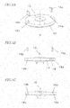
- FIG. 1A shows the external appearance of a substrate 10 for sample analysis.
- FIG. 1B shows a cross section of the substrate 10 for sample analysis.
- the surface of the substrate 10 for sample analysis shown in FIG. 1A will be referred to as the "upper surface”, the opposite surface from the upper surface as the “lower surface”, and the other surface extending between the upper surface and the lower surface as the "side surface”.
- the upper surface and the lower surface are each a surface to which the normal extends in parallel to the rotation axis P thereof. That is, it is assumed that the upper surface and the lower surface are perpendicular to the rotation axis P and parallel to each other. However, the upper surface and the lower surface do not need to extend parallel to each other across the entire area thereof. They may be locally or generally non-parallel to each other. At least one of the upper surface and the lower surface may include depressed portions or protruding portions.
- one side of the substrate 10 for sample analysis will be referred to as the "upper surface” and the other side thereof as the "lower surface”.
- FIG. 1B shows a cross section of the substrate 10 for sample analysis taken along a plane including the rotation axis P.
- the substrate 10 for sample analysis generally has a disc shape.
- the substrate 10 for sample analysis with a liquid having been injected into the inside thereof, is set in a sample analysis device to be described below.
- the sample analysis device transfers, distributes and mixes the liquid in the substrate 10 for sample analysis by rotating the substrate 10 for sample analysis. Then, the sample analysis device stops the rotation of the substrate 10 for sample analysis, for example, and optically analyzes the mixed liquid.
- the rotation axis P of the substrate 10 for sample analysis shown in FIG. 1A is the center of rotation about which the sample analysis device rotates the substrate 10 for sample analysis. Note that the substrate 10 for sample analysis is supported and rotated while the rotation axis P is in the range of 0° or more and 90° or less with respect to the vertical direction.
- a liquid is transferred, distributed and mixed in the substrate 10 for sample analysis by using various chambers and channels formed inside the substrate 10 for sample analysis.
- a liquid injected into the first chamber is transferred into the second chamber via the channel.
- a first chamber, a second chamber, a third chamber, a first channel connecting between the first chamber and the second chamber, and a second channel connecting between the first chamber and the third chamber are provided in the substrate 10 for sample analysis, a liquid injected into the first chamber is distributed between the second chamber and the third chamber via the first channel and the second channel.
- first chamber a first chamber, a second chamber, a third chamber, a first channel connecting between the first chamber and the third chamber, a second channel connecting between the second chamber and the third chamber are provided in the substrate 10 for sample analysis
- liquids injected into the first and second chambers are transferred into the third chamber to be mixed together in the third chamber.
- Transfer of a liquid between chambers via channels can be achieved by any of various methods.
- the substrate 10 for sample analysis is supported with the rotation axis P inclined in the range of greater than 0° and 90° or less with respect to the vertical direction. Then, the rotational angle position of the substrate 10 for sample analysis is changed, whereby the chamber from which the liquid is transferred is located higher than the chamber to which the liquid is transferred. Now, “higher” means higher in the vertical direction. Thus, it is possible to transfer a liquid to another chamber by using the gravity.
- the channel connecting between chambers is not a capillary channel.
- the substrate 10 for sample analysis is preferably supported with the rotation axis P inclined by 5° or more with respect to the vertical direction.
- the rotation axis P of the substrate 10 for sample analysis is more preferably 10° or more and 45° or less with respect to the vertical direction.
- the substrate 10 for sample analysis is even more preferably supported with the rotation axis P inclined in the range of 20° or more and 30° or less with respect to the vertical direction. This is because if the substrate 10 for sample analysis is supported with an inclination angle less than 5°, the gravity acting upon the liquid in the substrate 10 for sample analysis may be insufficient to provide a driving force needed to transfer the liquid.
- the term "capillary channel” refers to a channel having a narrow space such that the inside of the capillary channel can be filled with a liquid by virtue of the capillary tube action.
- a capillary tube is referred to also as a capillary channel.
- the cross section perpendicular to the direction in which the capillary channel extends may have a width of 0.1 mm to 5 mm and a depth of 50 ⁇ m to 300 ⁇ m, a width of 50 ⁇ m or more (preferably 50 ⁇ m to 300 ⁇ m) and a depth of 0.1 mm to 5 mm, or a width of 5 mm or less and a depth of 50 ⁇ m to 300 ⁇ m.
- an air vent needs to be provided also on the first chamber side, i.e., at the inlet of the capillary channel, in view of the air pressure in the chambers and in the channel.
- the substrate 10 for sample analysis is rotated at a rotation speed such that the centrifugal force acting upon the liquid inside the capillary channel due to the rotation of the substrate 10 for sample analysis is greater than the capillary force acing upon the liquid inside the capillary channel.
- the liquid inside the first chamber can be transferred into the second chamber if the second chamber is located farther away from the rotation axis P than the first chamber.
- the capillary force can be improved by performing a hydrophilic treatment on the wall surface inside the capillary channel.
- the hydrophilic treatment can be done by applying a non-ionic, cationic, anionic or amphoteric ionic surfactant on the wall surface of the first chamber and each liquid sample spot application port, by performing a corona discharge treatment thereon, by physically forming minute irregularities on the surface, and the like (see, for example, Japanese Laid-Open Patent Publication No. 2007-3361 ).
- the substrate 10 for sample analysis does not need to be disc-shaped.
- the substrate 10 for sample analysis may be sector-shaped, or may employ any of various shapes such as square, rectangular, diamond-shaped, hexagonal, etc.
- the substrate 10 for sample analysis includes a base substrate 12, a magnet 16a, a balancer 16b, a magnet-accommodating chamber 18a and a balancer-accommodating chamber 18b.
- the base substrate 12 is a member having a predetermined thickness, with the above-described rotation axis P running therethrough.
- the base substrate 12 is preferably formed to having a transmittance of 60% or more, using a material such as an acrylic, a polycarbonate or a polystyrene.
- the magnet 16a is provided for the B/F separation described above.
- the magnet 16a may be a magnet that is commonly used in an immunoassay of the competitive assay using magnetic particles, and may be a neodymium magnet or a ferrite magnet.
- FIG. 1B shows a reaction chamber 14.
- the reaction chamber 14 is a space where magnetic particles are captured by a magnet at least in the B/F separation.
- the magnet 16a can be inserted/removed into/from the magnet-accommodating chamber 18a of the base substrate 12.
- the insertion/removal is done from the upper surface of the substrate 10 for sample analysis.
- the magnet 16a is inserted into a position in the vicinity of the wall surface of the reaction chamber 14.
- This wall surface is a surface perpendicular to the direction in which the centrifugal force is exerted.
- the centrifugal force is a force exerted in the outward direction as the substrate 10 for sample analysis rotates, and is received by a liquid sample containing magnetic particles.
- the wall surface of the reaction chamber 14 closer to the magnet 16a supports the liquid sample against the centrifugal force while the substrate 10 for sample analysis is rotating.
- the balancer 16b is provided so that the center of gravity of the substrate 10 for sample analysis generally coincides with the rotation axis P. As the magnet 16a is attached to the substrate 10 for sample analysis, the center of gravity of the substrate 10 for sample analysis is moved off the rotation axis P. Therefore, the position of the center of gravity is adjusted by the balancer 16b. Note that there is no particular limitation on the shape and material of the balancer 16b.
- the center of gravity generally coinciding with means that the coincidence does not need to be exact. The reason is that the position of the center of gravity of the substrate 10 for sample analysis with no sample therein is different from that of the substrate 10 for sample analysis with a sample therein. Moreover, the position of the center of gravity can also be varied by the transfer of a sample, etc. Therefore, the center of gravity of the substrate 10 for sample analysis, unused, does not need to exactly coincide with the rotation axis P. That is, “generally coinciding” means that the center of gravity is such that a sample analysis device 1, to be described below, can rotate the substrate 10 for sample analysis with various liquids, the magnet 16a and the balancer 16b held therein at least at a predetermined rotation speed.
- the balancer 16b can be inserted/removed into/from the balancer-accommodating chamber 18b of the base substrate 12.
- the insertion/removal is done from the upper surface of the substrate 10 for sample analysis.
- the magnet 16a and the balancer 16b may have the same weight.
- the magnet 16a and the balancer 16b may not arranged in symmetry with respect to the rotation axis P, there is a need to adjust the weight of the magnet 16a and that of the balancer 16b depending on the positions thereof.
- the specific weights can be prescribed when designing the substrate 10 for sample analysis. Note that there may be a plurality of magnets 16a, and there may be a plurality of balancers 16b.
- the user When a user inserts the magnet 16a and the balancer 16b into the magnet-accommodating chamber 18a and the balancer-accommodating chamber 18b, respectively, the user may inadvertently switch them around.
- the shape of the magnet 16a may be different from that of the balancer 16b, or the magnet 16a and the balancer 16b may be distinguished from each other by using colors, marks or characters on at least one of them.
- the magnet-accommodating chamber 18a and the balancer-accommodating chamber 18b are spaces for accommodating the magnet 16a and the balancer 16b, respectively.
- the magnet-accommodating chamber 18a and the balancer-accommodating chamber 18b are depressed portions provided in the base substrate 12 so as to be in conformity with the shape of the magnet 16a and the balancer 16b.
- FIG. 1C shows the substrate 10 for sample analysis where the magnet 16a and the balancer 16b are accommodated in the magnet-accommodating chamber 18a and the balancer-accommodating chamber 18b, respectively.
- the magnet 16a and the balancer 16b may be provided fixedly on the base substrate 12.
- the substrate 10 for sample analysis may be manufactured, used and sold, with the magnet 16a and the balancer 16b both fixed on the base substrate 12.
- FIG. 1C shows a cross section of the substrate 10 for sample analysis, in the case where the magnet 16a is provided fixedly on the base substrate 12.
- the position of the magnet 16a may be appropriately changed by design.
- the position of the magnet 16a on the base substrate 12 as long as magnetic particles can be captured onto one of the wall surfaces inside the reaction chamber 14 (i.e., as long as the magnetic particles can be captured in the chamber).
- the magnet 16a may be provided on the bottom surface of the reaction chamber 14.
- an embodiment where the magnet 16a can be inserted/removed may be configured so that the magnet 16a can be inserted into the bottom surface of the reaction chamber 14.
- the magnet 16a may be provided on the upper surface of the reaction chamber.
- an embodiment where the magnet 16a can be inserted/removed may be configured so that the magnet 16a can be inserted into the upper surface of the reaction chamber 14.
- FIG. 2A and FIG. 2B show a variation regarding the magnet 16a and the balancer 16b of the substrate 10 for sample analysis.
- the top of the magnet 16a and the top of the balancer 16b are flush with or below the upper surface of the substrate 10 for sample analysis.
- the top of the magnet 16a and the top of the balancer 16b are projecting by a length d from the upper surface of the substrate 10 for sample analysis (see FIG. 2B ). This makes it easy to remove the magnet 16a and the balancer 16b. Particularly, it is easier to pull out the magnet 16a and the balancer 16b from the substrate 10 for sample analysis fixed to the sample analysis device before removing the substrate 10 for sample analysis from the sample analysis device.
- FIG. 3 shows a configuration of the sample analysis device 1 according to the present embodiment.
- the substrate 10 for sample analysis which has been loaded (set) in the sample analysis device 1, is rotated clockwise or counterclockwise, shaken and stopped at a predetermined position by the sample analysis device 1.
- the sample analysis device 1 can transfer, mix and analyze a liquid in the reaction chamber 14 in the substrate 10 for sample analysis.
- the sample analysis device 1 includes a motor 20, a driver circuit 22, an operation section 24, a magnet detection mechanism 26, a control circuit 30 and a display device 32.
- the substrate 10 for sample analysis on its lower surface, is detachably attached to the sample analysis device 1, and is not a component of the sample analysis device 1. Components of the sample analysis device 1 will now be outlined below.
- the motor 20 is a brushless motor including a permanent magnet rotor and a coil, for example.
- the rotor is 12-pole, and the coil is 3-phase.
- the brushless motor 20 is provided with a plurality of Hall elements.
- the motor 20 may be a brush motor or a stepping motor as long as the movement of the motor 20 is translated into the rotation of the substrate 10 for sample analysis.
- the driver circuit 22 primarily includes an inverter circuit and a circuit for controlling the operation of the inverter circuit (both not shown).
- the driver circuit 22 switches the current flow to the 3 phases of coils of the motor 20 in accordance with the rotation of the rotor of the motor 20, thereby controlling the rotation of the motor 20.
- the operation section 24 is an input device such as a touchscreen panel, a keyboard, or the like, and is used by a user for making necessary inputs for operating the sample analysis device 1.
- the operation section 24 may also be used for starting a magnet detection process to be described bellow.
- the magnet detection mechanism 26 detects whether or not the magnet 16a has been placed in the substrate 10 for sample analysis at the time of measurement.
- the specific configuration of the magnet detection mechanism 26 varies depending on the detection method. A plurality of configurations will now be described.
- the control circuit 30 is a CPU provided in the sample analysis device 1, for example.
- the control circuit 30 executes a computer program loaded on the RAM (not shown), thereby sending instructions to other circuits in accordance with the procedure of the computer program. Circuits receiving instructions operate as will be described hereinbelow, thereby implementing the functions of the circuits. Instructions from the control circuit 30 are sent to the driver circuit 22, the operation section 24, the magnet detection mechanism 26, the display device 32, etc., as shown in FIG. 3 , for example. Procedures of the computer program are illustrated in the flowcharts of the accompanying drawings.
- the RAM loaded with a computer program may be volatile or non-volatile.
- a volatile RAM is a RAM that cannot retain information stored thereon unless it is receiving power supply.
- DRAM dynamic random access memory
- a non-volatile RAM is a RAM that can retain information without power supply thereto.
- a magnetoresistance RAM (MRAM), a resistive RAM (ReRAM) and a ferroelectric memory (FeRAM) are example non-volatile RAMs.
- a non-volatile RAM is preferably employed.
- a volatile RAM and a non-volatile RAM are both examples of non-transitory computer-readable recording media.
- a magnetic recording medium such as a hard disk and an optical recording medium such as an optical disc are also examples of non-transitory computer-readable recording media. That is, the computer program of the present disclosure may be recorded on any of various non-transitory computer-readable media, other than media (transitory media) such as the air capable of propagating the computer program as a radio signal.
- the display device 32 is a liquid crystal display device, for example, for receiving and displaying a video signal output from the control circuit 30. Assuming that the operation section 24 is a touch panel, the operation section 24 can be provided as a part of the display device 32. In the present specification, the display device 32 is described as being provided in the sample analysis device 1. However, this configuration is merely an example. The display device 32 may be a device external to the sample analysis device 1.
- control circuit 30 includes a signal generation circuit 28, and the display device 32 includes a speaker 34.
- the signal generation circuit 28 When the detection result from the magnet detection mechanism 26 indicates an error, i.e., indicates that no magnet is detected, the signal generation circuit 28 generates a signal (notification signal) for outputting a sound, light or an image from the display device 32 or the speaker 34.
- the sound may be a warning beep, and the light may be warning light.
- the image may be a message such as "No magnet attached", and displayed on the display device 32.
- the notification signal there is no particular limitation on the embodiment of the notification signal as long as it can be visually or audibly recognized by a user.
- FIG. 4 shows an example procedure for measuring a sample using the sample analysis device 1.
- Steps S1 to S4 are operations done by a user of the sample analysis device 1, and step S5 and subsequent steps are operations performed by the sample analysis device 1.
- the user prepares the substrate 10 for sample analysis and the magnet 16a in step S1.
- the user attaches the magnet 16a to the substrate 10 for sample analysis in step S2.
- the user may prepare the balancer 16b in step S1, and attach the balancer 16b in step S2.
- the user introduces a sample (analyte) in the substrate 10 for sample analysis in step S3, and sets the substrate 10 for sample analysis in the sample analysis device 1 in step S4. Through this operation, the substrate 10 for sample analysis is rotatably fixed on the sample analysis device 1.
- step S5 the control circuit 30 causes the magnet detection mechanism 26 to execute a detection process for detecting the magnet 16a.
- step S6 the magnet detection mechanism 26 determines the presence/absence of the magnet 16a. The details of the determination process will be described below. As a result of the determination, control proceeds to step S7 if the magnet 16a is present, and proceeds to step S8 if the magnet 16a is absent.
- step S7 the control circuit 30 performs operations including shaking, rotating and stopping the substrate 10 for sample analysis in accordance with a predetermined procedure to measure the sample.
- the description of the specific details of the measurement is omitted in the present specification.
- step S8 if the control circuit 30 receives a signal indicating that the detection result from the magnet detection mechanism 26 is an error, the signal generation circuit 28 generates a notification signal.
- the display device 32 displays the error based on the notification signal.
- the magnet detection mechanism 26 detects the magnet 16a by using at least one method.
- FIG. 5 shows an example configuration of the sample analysis device 1 for optically detecting the magnet 16a.
- a photodetection device 26a and a light source 38 are provided as the magnet detection mechanism 26.
- the photodetection device 26a includes a light receiving element (not shown), a driver circuit and a voltage conversion circuit.
- the light receiving element generates a current value signal through photoelectric conversion under the control of the driver circuit, and the current value signal is converted into a voltage value signal.
- the voltage conversion circuit outputs the voltage value signal to the control circuit 30, and the control circuit 30 determines the presence/absence of the magnet by using the signal.
- the photodetection device 26a may be provided with an arithmetic circuit so that the photodetection device 26a determines the presence/absence of the magnet 16a.
- the light receiving element is arranged at a position such that it can receive light output from the light source 38.
- the light source 38 is arranged at a position such that the magnet in the substrate 10 for sample analysis can be illuminated when the substrate 10 for sample analysis is attached to the sample analysis device 1 and the substrate 10 for sample analysis is rotated.
- FIG. 6 shows a procedure of a method for detecting the magnet 16a by using the optical characteristic.
- step S11 the user operates the operation section 24 to instruct to start the magnet detection.
- step S11 corresponds to the process of accepting a press-down of the button.
- step S12 the control circuit 30 starts up the photodetection device 26a and the light source 38.
- step S13 the motor 20 rotates the substrate 10 for sample analysis.
- step S14 the photodetection device 26a starts detecting light from the light source 38.
- step S15 the control circuit 30 processes signals based on light detected by the photodetection device 26a to determine the presence/absence of the magnet 16a. The details of this process will now be described with reference to FIG. 7 .
- FIG. 7 shows an output result of the photodetection device 26a.
- This example shows an output result obtained for one rotation of the substrate 10 for sample analysis, assuming that the magnet 16a is attached.
- the horizontal axis represents time, and the vertical axis represents the detection result (output) of the photodetection device 26a.
- the photodetection device 26a When the rotation starts, light from the light source 38 is detected by the photodetection device 26a since the base substrate 12 allows light to pass therethrough. As the rotation continues, light hits the magnet 16a. Since the magnet 16a has zero transmittance, the photodetection device 26a does not detect light while the magnet 16a is passing therethrough. In FIG. 7 , the period D corresponds to the period over which the magnet 16a is passing therethrough. Then, after the magnet 16a has passed therethrough, the photodetection device 26a again detects light from the light source 38.
- the control circuit 30 sets a threshold value T, and the control circuit 30 can determine that the magnet 16a is attached if there is the period D over which the output is below the value. On the other hand, if the magnet is not attached, there will be no period over which the output is below the threshold value T. In such a case, the control circuit 30 can determine that the magnet 16a is not attached.
- the balancer 16b is formed by a material having a low transmittance, it is preferred that the magnet 16a and the balancer 16b are located at radially different positions. This is to prevent an erroneous detection when the balancer 16b is attached and the magnet 16a is not attached.
- the magnet 16a and the balancer 16b may be made different from each other in terms of their lengths in the rotation direction.
- the magnet 16a and the balancer 16b may be made different from each other in terms of their lengths in the rotation direction.
- the magnet 16a and the balancer 16b may be shaped so that they have different lengths in the rotation direction, it is possible to determine the presence/absence of each of the magnet 16a and the balancer 16b.
- the transmittance of the balancer 16b for light from the light source 38 is made different from that of the magnet 16a, it is possible to distinguish the magnet 16a and the balancer 16b from each other.
- the transmittance for light from the light source 38 can be set as follows by changing the material, etc.
- T1 and T2 threshold values set in advance
- T1 ⁇ T2 threshold values
- T1 ⁇ T2 threshold values set in advance
- the balancer 16b is present if there is a period over which the output result is lower than the threshold value T2 and higher than the threshold value T1. Also with such a configuration, it is possible to determine the presence/absence of each of the magnet 16a and the balancer 16b.
- FIG. 8 shows an example configuration of the sample analysis device 1 for detecting the presence/absence of a magnetic force of the magnet 16a.
- the magnetic force detection device 26b is provided as the magnet detection mechanism 26.
- the magnetic force detection device 26b includes, for example, an element for outputting a voltage or opening/closing a switch in accordance with the magnetic force, a driver circuit and a voltage conversion circuit.
- the element for outputting a voltage in accordance with the magnetic force may be a Hall element.
- the element for opening/closing a switch in accordance with the magnetic force may be a reed switch. An example using a Hall element will now be described.
- the magnetic force detection device 26b outputs the voltage signal from a Hall element to the control circuit 30, and the control circuit 30 determines the presence/absence of the magnet.
- the magnetic force detection device 26b may be provided with an arithmetic circuit, and the photodetection device 26a may determine the presence/absence of the magnet 16a.
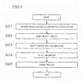
- FIG. 9 shows a procedure of a method for detecting the magnet 16a by using a magnetic characteristic.
- step S21 the user operates the operation section 24 to instruct to start the magnet detection.
- step S21 corresponds to the process of accepting a press-down of the button.
- step S22 the control circuit 30 starts up a Hall element of the magnetic force detection device 26b.
- step S23 the motor 20 rotates the substrate 10 for sample analysis.
- step S24 the Hall element of the magnetic force detection device 26b detects magnetism.
- the Hall element outputs a voltage signal in accordance with the intensity of the magnetic force.
- step S25 the control circuit 30 processes the voltage signal output from the Hall element of the magnetic force detection device 26b to determine the presence/absence of the magnet 16a. The details of this process will now be described with reference to FIG. 10 .
- FIG. 10 shows an output result of the Hall element of the magnetic force detection device 26b.
- This example shows an output result obtained for one rotation of the substrate 10 for sample analysis, assuming that the magnet 16a is attached.
- the horizontal axis represents time, and the vertical axis represents the detection result (output) of the magnetic force detection device 26b. Note that FIG. 10 shows the output result under the following conditions.
- the Hall element When the rotation starts, the Hall element outputs only a relatively small voltage in a situation where the magnet 16a and the Hall element are located away from each other. As the rotation continues, the magnet 16a comes closer to the Hall element and then moves away from the Hall element after reaching the closest point. In FIG. 10 , the period D corresponds to a situation where the magnet 16a comes closer to the Hall element and then moves away therefrom after reaching the closest point. After the magnet 16a passes, the magnet 16a and the Hall element move are away from each other, and the Hall element therefore outputs only a relatively small voltage.
- the control circuit 30 can determine that the magnet 16a is attached if there is the period D over which the output exceeds the value. On the other hand, if the magnet is not attached, there will be no period over which the output exceeds the threshold value T. In such a case, the control circuit 30 can determine that the magnet 16a is not attached.
- step S23 may determine that the magnet 16a is attached if the output of the Hall element exceeds a predetermined threshold value and that the magnet 16a is not attached if the output does not exceed the predetermined threshold value.
- FIG. 11 shows an example configuration of the sample analysis device 1 for detecting the presence/absence of the magnet 16a based on the weight of the substrate 10 for sample analysis.
- a weight measurement circuit 42 is provided as the magnet detection mechanism 26. Note that as will be discussed below, the operation is relatively simple, and a description using a flowchart will be omitted. Note however that as long as the control circuit 30 operates, the process thereof can be implemented by a program to be executed as follows.
- the weight measurement circuit 42 is a strain gauge, which is a mechanical sensor for measuring the strain of an object, for example.
- the load to be sensed by the strain gauge and the amount of strain will be specified in advance at the time of design, depending on the type of a strain gauge to be used.
- the control circuit 30 can detect the current load based on the amount of strain of the weight measurement circuit 42 . If it is indicated that the load is 14.7 grams, the control circuit 30 can determine that the magnet 16a is present in the substrate 10 for sample analysis. On the other hand, if it is indicated that the load is 14.0 grams, the control circuit 30 can determine that the magnet 16a is absent in the substrate 10 for sample analysis.
- FIG. 12 shows an example configuration of the sample analysis device 1 for detecting the presence/absence of the magnet 16a based on the motor rotational load when the substrate 10 for sample analysis is set.
- a load detection circuit 26c is provided in the driver circuit 22 as the magnet detection mechanism 26. Note that as will be discussed below, the operation is relatively simple, and a description using a flowchart will be omitted. Note however that as long as the control circuit 30 operates, the process thereof can be implemented by a program to be executed as follows.
- the load detection circuit 26c detects the rotational load of the motor 20.
- the rotational load varies dependent on the weight of the substrate 10 for sample analysis to be rotated.
- the operating principle of this example utilizes the fact that the weight of the magnet 16a increases the load on the motor 20 rotating the substrate 10 for sample analysis. That is, it is possible to determine whether or not the magnet 16a is present based on the load on the motor 20 detected by the load detection circuit 26c.
- the motor 20 driven by the driver circuit 22 rotates the substrate 10 for sample analysis at a constant rotation speed (e.g., 1000 rpm), and the load detection circuit 26c measures the value of the load current.
- the value X1 of the load current to be measured when the magnet 16a is present and the value X2 of the load current to be measured when the magnet 16a is absent are specified in advance at the time of design.
- the load increases by the weight of the magnet 16a . Therefore, the values X1 and X2 have the relationship of X1>X2.
- the control circuit 30 can determine the presence/absence of the magnet 16a based on the value of the load current measured by the load detection circuit 26c.
- a constant load current may be provided to the motor 20 to rotate the substrate 10 for sample analysis, and then the rotation speed can be measured to determine the presence/absence of the magnet 16a .
- the motor 20 driven by the driver circuit 22 rotates the substrate 10 for sample analysis at a constant rotation speed (e.g., 1000 rpm), and then the load detection circuit 26c measures the rotation speed.
- the value X3 of the rotation speed to be measured when the magnet 16a is present and the value X4 of the rotation speed to be measured when the magnet 16a is absent are specified in advance at the time of design.
- the load increases by the weight of the magnet 16a . Therefore, the values X3 and X4 have the relationship of X3 ⁇ X4.
- the control circuit 30 can determine the presence/absence of the magnet 16a based on the value of the rotation speed measured by the load detection circuit 26c.
- the control circuit 30 may use a notification signal to notify the user of the presence/absence of the magnet 16a, or the absence of one of the magnet 16a and the balancer 16b.
- the control circuit 30 can use a notification signal to notify the user of the absence of the magnet 16a or the balancer 16b.
- the driving voltage may be measured.
- the acceleration value used when increasing the rotation speed varies depending on the presence/absence of the magnet 16a (including the balancer 16b ).
- the acceleration of the substrate 10 for sample analysis in which the magnet 16a is present is smaller than the acceleration of the substrate 10 for sample analysis in which the magnet 16a is absent. Any of the acceleration values can be specified by design.
- the presence/absence of the magnet 16a can be detected by using such acceleration.
- Various methods are possible for detecting the acceleration. For example, where a Hall element is provided in the motor 20, the driver circuit 22 can determine the acceleration of the rotor of the motor 20, i.e., the value of the rotational acceleration of the substrate 10 for sample analysis, based on the output value of the Hall element.
- FIG. 13A to FIG. 13C a variation of the substrate 10 for sample analysis will be described with reference to FIG. 13A to FIG. 13C , FIG. 14A , FIG. 14B , FIG. 15A and FIG. 15B .
- FIG. 13A shows the external appearance of a substrate 110 for sample analysis according to the variation.
- the substrate 10 for sample analysis described above is configured so that the magnet 16a , the balancer 16b , and the like, can be removed, as parts, from the base substrate 12.
- the substrate 110 for sample analysis is includes two parts combined together.
- FIG. 13B shows a base substrate 110a of the substrate 110 for sample analysis
- FIG. 13C shows a magnet unit 110b of the substrate 110 for sample analysis.
- the substrate 110 for sample analysis includes the base substrate 110a and the magnet unit 110b to be fitted together.
- the base substrate 110a includes the magnet-accommodating chamber 18a and the balancer-accommodating chamber 18b . Moreover, the base substrate 110a includes a plurality of fixation holes 18c. Note that there is no particular limitation on the number of holes 18c.
- the magnet unit 110b is provided with the magnet 16a and the balancer 16b , and is further provided with fixation bosses 16c.
- the magnet 16a and the balancer 16b are fixed to the magnet unit 110b .
- FIG. 14A and FIG. 14B are a top view and a cross-sectional view of the base substrate 110a .
- FIG. 15A and FIG. 15B are a top view and a side view of the magnet unit 110b.
- the magnet 16a and the balancer 16b are inserted into the magnet-accommodating chamber 18a and the balancer-accommodating chamber 18b , and the fixation bosses 16c are inserted into the fixation holes 18c, thereby fixing the substrate 110 for sample analysis with respect to the rotation direction.
- the magnet unit 110b is provided to be attached to the base substrate 110a at the lower surface so as to be detachable off the lower surface in the example of FIGS. 13A to 15B , this is merely an example.
- the magnet unit 110b may be attached to the base substrate 110a at the upper surface so as to be detachable off the upper surface.
- the magnet unit 110b may be attached to the base substrate 110a at the side surface so as to be detachable off the side surface.
- the magnet unit 110b and the base substrate 110a may be configured as if they were pieces of the substrate 10 for sample analysis cut along a plane parallel to the rotation axis.
- one of the pieces that includes the magnet 16a is referred to as the magnet unit 110b
- the other piece including the magnet-accommodating chamber 18a is referred to as the base substrate 110a .
- the magnet unit 110b can be attached to the base substrate 110a at the side surface so as to be detachable off the side surface.
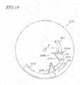
- FIG. 16 is an example top view (or bottom view) of a substrate 200 for sample analysis according to the present embodiment. Note that the definitions of the "upper surface” and the “lower surface” are as set forth above in Embodiment 1 in conjunction with FIG. 1A .
- the substrate 200 for sample analysis includes the rotation axis P, the magnet 16a , a first chamber 201 having the first space, a second chamber 202 having the second space, and a third chamber 203 having the third space. Note that FIG. 16 does not show the balancer 16b.
- the substrate 200 for sample analysis includes a first channel 205 connecting between the first chamber 201 and the second chamber 202, and a second channel 206 connecting between the second chamber 202 and the third chamber 203.
- the word "connect” as used herein means to connect chambers together so that a liquid sample can be transferred therebetween.
- the shapes of the first chamber 201, the second chamber 202 and the third chamber 203, and the arrangement thereof in the substrate 200 for sample analysis will be described.
- the first chamber 201 will be described.
- the connecting portion between the first chamber 201 and the first channel 205 is located on one of the wall surfaces of the first chamber 201 extending in parallel to the rotation axis that is farthest from the rotation axis (the outermost wall surface) or on a side surface that is adjacent to the outermost wall surface. This is because when transferring a liquid from the first chamber 201 to the second chamber 202, it is possible to prevent some of the liquid from remaining in the first chamber 201.
- this configuration may depend on the shape of the first chamber 201.
- FIG. 16 shows example air vents H1 provided in the first chamber 201.
- Symbols "o" of the same shape in FIG. 16 each denote an air vent.
- the position of each air vent is no particular limitation the position of each air vent as long as the air vent is not filled with a liquid when a liquid is introduced into the chamber. The position may be on a side surface portion that is close to the rotation axis or on a side surface portion of the side wall that is on the side closer to the rotation axis. This similarly applies to the symbols "o" in the second chamber 202 and the third chamber 203 to be described next.
- the connecting portion between the second chamber 202 and the first channel 205 is located on one of the wall surfaces of the second chamber 202 extending in parallel to the rotation axis that is closest to the rotation axis (the innermost wall surface) or on a side wall that is adjacent to the innermost wall surface (preferably, an inner side portion thereof).
- this configuration may depend on the shape of the second chamber 202 .
- first channel 205 and the second channel 206 are capillary channels, they need to have (at least one) air vent.
- FIG. 16 shows example air vents H2 provided in the second chamber 202.
- the position of the second chamber 202 needs to be farther away from the rotation axis P than the first chamber 201.
- the configuration of the third chamber 203 is basically similar to that of the second chamber 202. That is, there is no particular limitation on the shape of the third chamber 203, and the third chamber 203 needs to have an air vent. It is basically preferred that the connecting portion between the third chamber 203 and the second channel 206 is located on one of the wall surfaces of the third chamber 203 extending in parallel to the rotation axis that is closest to the rotation axis (the innermost wall surface) or on a side wall that is adjacent to the innermost wall surface (preferably, an inner side portion thereof). Note however that the position of the third chamber 203 needs to be farther away from the rotation axis P than the second chamber 202.
- the first channel 205 has a first bend 205a and a second bend 205b along the first channel 205 from the first chamber 201 to the second chamber 202.
- the first bend 205a has a shape that is projecting away from the rotation axis P
- the second bend 205b has a shape that is projecting toward the rotation axis P.
- the first bend 205a is located between the first chamber 201 (one of the two chambers 201 and 202 connected together by the first channel 205 that is located closer to the rotation axis P) and the second bend 205b.
- R1>R2 is satisfied, where R1 is the distance between the rotation axis P and a side surface of the chamber 202 (one of the two chambers 201 and 202 connected together by the first channel 205 that is located farther away from the rotation axis P) that is closest to the rotation axis, and R2 is the distance between the rotation axis P and a point in the first bend 205a that is farthest away from the rotation axis P.
- R4>R3 is satisfied, where R4 is the distance from the rotation axis P to the liquid surface of the liquid held in the chamber 201 (located closer to the rotation axis P ), where the liquid is held against a side surface of the chamber 201 due to the centrifugal force, and R3 is the distance from the rotation axis P to a point in the second bend 205b that is closest to the rotation axis P.
- the motor 20 When the motor 20 is rotating the substrate 200 for sample analysis at a certain rotation speed, a liquid sample is transferred from the first chamber 201 to the second chamber 202 via the first channel 205. While this rotation is maintained, the liquid sample will not be transferred from the second chamber 202 to the third chamber 203. Assuming that the same capillary force acts upon a liquid in the first channel 205 and a liquid in the second channel 206, the "rotation speed" as used herein is such that the centrifugal force acting upon the liquid due to the rotation of the substrate 10 for sample analysis is greater than the capillary force acting upon the liquid in the second channel 206.
- the motor 20 rotates the substrate 10 for sample analysis at this rotation speed, thereby transferring the liquid sample from the first chamber 201 to the second chamber 202 via the first channel 205, a part of the liquid sample in the second chamber fills a portion of the second channel 206. That is, although the liquid sample having been transferred to the second chamber 202 is drawn into the second channel 206 due to the capillary force of the second channel 206, the centrifugal force due to the rotation of the substrate 10 for sample analysis is greater than this capillary force. Therefore, the second channel 206 is filled with the liquid sample only to the same height as the height (the distance from the rotation axis P) of the liquid surface of liquid sample in the second chamber 202.
- the rotation speed thereof is adjusted (including a case where the rotation is stopped) so that the centrifugal force acting upon the liquid sample in the second channel 206 is less than the capillary force acting upon the liquid sample in the second channel 206.
- the second channel 206 is filled by a part of the liquid in the second chamber 202 due to the capillary action. Moreover, as the motor 20 rotates the substrate 200 for sample analysis while the second channel 206 is filled with the liquid, the centrifugal force exceeds the capillary force at a certain point in time. Then, the second channel 206 discharges the liquid from the second chamber 202 into the third chamber 203. As a result, due to the siphon principle, the liquid sample in the second chamber 202 is transferred to the third chamber 203 via the second channel 206. Note that the third chamber 203 is located farther away from the rotation axis P than the second chamber 202, as described above.
- the third chamber 203 can be said to be located lower (farther) than the second chamber 202.
- the movement of a liquid through channels as described above will be referred to as the capillary action and the siphon principle. That is, the term "syphon principle" as used herein refers to the transfer being controlled by the balance between the centrifugal force acing upon the liquid due to the rotation of the substrate 10 for sample analysis and the capillary force of the channels. With the provision of a capillary channel and a siphon structure, a liquid can be transferred into a chamber via the channel.
- the first chamber 201 is a reaction field where a magnetic particle immobilized antibody 305, an antigen 306 and a labeled antibody 308 are reacted together, eventually producing a complex 310. Therefore, a liquid containing the magnetic particle immobilized antibody 305, an analyte solution containing the antigen 306 and a liquid containing the labeled antibody 308 may be dispensed into the first chamber 201 , thereby producing the complex 310.
- an immunoassay can be performed in accordance with the procedure shown in FIG. 17 using other chambers and channels.
- the substrate 200 for sample analysis may include three additional chambers and channels, so that a solution containing the magnetic particle immobilized antibody 305, an analyte solution containing the antigen 306 and a solution containing the labeled antibody 308 are separately held in the three chambers.
- Each of the chambers is connected to the first chamber 201 via a channel. Then, the liquids are transferred from the three additional chambers to the first chamber 201 via the channels, thereby producing the complex 310.
- the magnetic particle immobilized antibody 305 and/or the labeled antibody 308 may be dried (referred to hereinafter as a "dry reagent"), and this dry reagent may be held in the first chamber 201 and dissolved in a liquid containing the antigen 306, thereby producing the complex 310.
- the liquid containing the antigen 306 may be dispensed into the first chamber 201 or may be transferred into the first chamber 201 from another separate chamber via a channel.
- dry reagents held in other chambers may be dissolved with a predetermined solution, at the time of measurement, so that liquids containing the antigen 306 are transferred to the first chamber 201 via respective channels to be mixed together in the first chamber 201, thereby producing the complex 310.
- the B/F separation is performed in the second chamber 202.
- the liquid containing the complex 310 in the first chamber 201 is transferred to the second chamber 202 via the first channel 205.
- the magnetic particles 302 containing the complex 310 are captured onto the wall surface of the second chamber 202 by the magnetic force of the magnet 16a .
- the third chamber 203 holds a liquid that is no longer needed in the second chamber 202.
- the liquid not needed is discharged from the second chamber 202 to the third chamber 203 via the second channel 206.
- the magnet 16a is arranged at a position in the vicinity of the wall surface of the second chamber 202.
- This wall surface is a surface perpendicular to the direction in which the centrifugal force is exerted.
- the centrifugal force is a force exerted in the outward direction as the substrate 200 for sample analysis rotates, and is received by a liquid sample containing the magnetic particles 302.
- the wall surface of the reaction chamber 14 closer to the magnet 16a supports the liquid sample against the centrifugal force while the substrate 200 for sample analysis is rotating. Note that there is no particular limitation on the position of the magnet 16a as long as magnetic particles can be captured onto the wall surface of the second chamber 202.
- FIG. 16 shows an example configuration using the siphon principle. The capillary action and the siphon principle will be described by using an example in which a liquid is transferred from the second chamber 202 to the third chamber 203 shown in FIG. 16 .
- the motor 20 rotates the substrate 200 for sample analysis at a high speed, a liquid sample is transferred from the first chamber 201 to the second chamber 202.
- rotation at a high speed refers to a rotation speed that imposes a centrifugal force greater than a predetermined force on the liquid in the substrate 200 for sample analysis.
- a rotation speed that imposes a centrifugal force greater than a predetermined force means a rotation speed such that the rotation of the substrate 200 for sample analysis generates a centrifugal force that prevents a liquid such as a reaction solution from being moved by the gravity, and such that a centrifugal force greater than the capillary force of each capillary channel can be imposed. This similarly applies hereinbelow.
- the liquid sample in the second chamber 202 is not transferred to the third chamber 203 via the second channel 206.
- the substrate 200 for sample analysis is rotated at a rotation speed such that the centrifugal force is less than the capillary force of the capillary channel (including a case where the rotation is stopped)
- a part of the liquid in the second chamber 202 fills the second channel 206 due to the capillary action.
- the motor 20 rotates the substrate 200 for sample analysis while the second channel 206 is filled with a liquid
- the liquid in the second chamber 202 starts to be transferred to the third chamber 203 at a point in time when the centrifugal force exceeds the capillary force.
- the liquid sample is continuously transferred from the second chamber 202 to the third chamber 203 due to the siphon principle as long as the motor 20 maintains a rotation speed greater than or equal to this rotation speed.
- the first channel 205 and the second channel 206 are each preferably a capillary channel capable of drawing and transferring a liquid by virtue of the capillary action.
- first channel 205 and the second channel 206 do not necessarily need to be channels using the capillary action.
- a liquid is transferred from the first chamber 201 to the third chamber 203 via the second chamber 202, wherein the transfer of the liquid between the second chamber 202 and the third chamber 203 is controlled.
- the substrate 200 for sample analysis is supported with the rotation axis P being in the range of greater than 0° and 90° or less with respect to the vertical direction.
- the first chamber 201 is shaped so that a liquid can be held in the first chamber 201 at a certain rotational angle position.
- the first chamber 201 is further shaped so that when the rotational angle of the substrate 200 for sample analysis is changed, the liquid held in the first chamber 201 is allowed to flow into the second chamber 202 via the first channel 205.
- the outermost wall surface of the first chamber 201 (the wall surface farthest away from the rotation axis P) is depressed so that the outermost wall surface is capable of holding the liquid sample when the substrate 200 for sample analysis is held at a predetermined angle.
- the second channel 206 may be a capillary channel (including a siphon structure) or a channel that is capable of transferring a liquid sample by using the gravity. Note however that where the second channel 206 is a channel that is capable of transferring a liquid sample by using the gravity, the outermost wall surface of the second chamber 202 is preferably depressed, as is the first chamber 201 described above.
- the substrate 200 for sample analysis illustrated in the present embodiment assumes that the reaction to produce the complex 310 is performed in the first chamber 201, not in the second chamber 202. This is because if the reaction to produce the complex 310 is performed in the second chamber 202, the reaction to produce the complex 310 will be performed with the magnetic particles captured by the magnet 16a onto the wall surface of the second chamber 202.
- the reaction to produce the complex 310 will be performed with the positions of the magnetic particles substantially fixed, thereby deteriorating the reaction efficiency and increasing the amount of time required for the complex-producing reaction.
- a luminescent substrate or a chromogenic substrate held in a chamber may be transferred to the second chamber 202, after the reaction to produce the complex 310 is complete, thereby causing a luminescent or chromogenic reaction.
- a cleaning liquid held in a chamber may be transferred to the second chamber 202, after the reaction to produce the complex 310 is complete, thereby cleaning (and discharging) the magnetic particles 302. Attempting to complete such a step within the substrate 200 for sample analysis, different liquids need to be transferred to the second chamber 202 containing the magnetic particles 302 at predetermined points in time via different chambers and channels provided separately.
- a part of the luminescent substrate or the chromogenic substrate or a part of the cleaning liquid may possibly be transferred into a chamber containing the magnetic particles 302 (e.g., the second chamber 202) at unintended points in time, e.g., during the reaction to produce the complex 310, because of the rotation control for the substrate 200 for sample analysis.
- the substrate 200 for sample analysis of the present embodiment separately includes a chamber for producing the complex 310 and a chamber for performing the B/F separation.
- FIG. 18A to FIG. 18C an example of a liquid sample transferring procedure to be performed in the substrate 200 for sample analysis according to the present embodiment will be described referring to FIG. 18A to FIG. 18C .
- the first channel 205 and the second channel 206 to be described here are capillary channels and they both transfer liquids based on the siphon principle described above.
- FIG. 18A shows the substrate 200 for sample analysis with a liquid sample introduced into the first chamber 201.
- a liquid sample is shown by hatching in the first chamber 201.
- the substrate 200 for sample analysis is set in the sample analysis device 1, and the magnetic particle immobilized antibody 305, an antigen and a labeled antibody are introduced into the first chamber 201.
- introduction methods may be used.
- the operator may dispense different liquids directly into the first chamber 201, or the liquids may be dispensed into the respective chambers 201 to 203 and transferred to the first chamber 201 as the sample analysis device 1 controls the rotation.
- the complex 310 will be eventually produced in the first chamber 201.
- the sample analysis device 1 may allow the complex 310 to be produced, when the substrate 200 for sample analysis is at a halt.
- the substrate 200 for sample analysis may be shaken within a predetermined angle range.
- the liquid sample in the first chamber 201 (also including the magnetic particles 302) is drawn into the first channel 205 by virtue of the capillary action, filling the first channel 205.
- FIG. 18B shows the substrate 200 for sample analysis after the liquid sample is transferred from the first chamber 201 to the second chamber 202.
- the liquid sample having been transferred to the second chamber 202 will not be transferred to the third chamber 203 via the second channel 206.
- the magnetic particles 302 in the liquid sample are generally captured by the magnetic force of the magnet 16a onto the wall surface of the second chamber 202.
- the liquid in the second chamber 202 (which does not substantially contain the magnetic particles 302) is drawn into the second channel 206 by virtue of the capillary action, filling the second channel 206.
- the sample analysis device 1 rotates the substrate 200 for sample analysis at a high speed.
- the liquid sample in the second chamber 202 of the substrate 200 for sample analysis undergoes the centrifugal force to be transferred to the third chamber 203 via the second channel 206.
- the magnetic particles 302 remain held in the second chamber 202.
- FIG. 18C shows the substrate 200 for sample analysis in which the liquid sample, etc., have been transferred to the third chamber 203.
- the present embodiment has been directed to an example where the magnet 16a is placed in the substrate 200 for sample analysis.
- a magnet may be provided in the sample analysis device, not in the substrate for sample analysis.
- FIG. 19 shows a configuration of a sample analysis device 100 according to a variation. Like components to those of the sample analysis device 1 shown in FIG. 3 or the sample analysis device shown in FIG. 5 or FIG. 8 will be denoted by like reference numerals and will not be described below.
- the sample analysis device 100 includes an arm 41 mechanically coupled to a bearing 40 having the rotation axis P, with a magnet 16d provided at the tip of the arm 41.
- a substrate 210 for sample analysis used with this configuration may only need to include the magnet-accommodating chamber 18a into which a magnet is inserted, for example.
- the opening of the magnet-accommodating chamber 18a may be provided on the upper surface of the substrate 210 for sample analysis or on the lower surface thereof. Alternatively, the opening may be a hole running through the upper surface and the lower surface of the substrate 210 for sample analysis.
- the position and the size of the magnet 16d are adjusted so that the magnet 16d can be inserted into the magnet-accommodating chamber 18a ( FIG. 1B ).
- the magnet-accommodating chamber 18a accommodates the magnet 16d provided in the sample analysis device 100, and also functions as a lock mechanism used when the substrate 210 for sample analysis is rotated by the motor 20 and/or as a torque transmission mechanism.
- the internal configuration of the substrate 210 for sample analysis may be the same as those of the substrate 10 for sample analysis and the substrate 200 for sample analysis. That is, also the substrate 210 for sample analysis may only need to include the first chamber 201, the second chamber 202 and the first channel 205, for example.
- the sample analysis device 100 described above does not include the magnet detection mechanism 26 ( FIG. 3 ). Since the magnet 16d is inserted every time the substrate 210 for sample analysis is set, there is no need to detect the presence/absence of the magnet. Note that the balancer does not need to be provided on the substrate 210 for sample analysis or provided on the sample analysis device 100.
- the present disclosure is applicable to a substrate for sample analysis and a sample analysis device used for analyzing a particular component of an analyte.
Landscapes
- Health & Medical Sciences (AREA)
- Life Sciences & Earth Sciences (AREA)
- Immunology (AREA)
- Chemical & Material Sciences (AREA)
- Engineering & Computer Science (AREA)
- Hematology (AREA)
- Urology & Nephrology (AREA)
- Biomedical Technology (AREA)
- Molecular Biology (AREA)
- General Health & Medical Sciences (AREA)
- Analytical Chemistry (AREA)
- Physics & Mathematics (AREA)
- Food Science & Technology (AREA)
- Biotechnology (AREA)
- Cell Biology (AREA)
- Microbiology (AREA)
- Medicinal Chemistry (AREA)
- Biochemistry (AREA)
- General Physics & Mathematics (AREA)
- Pathology (AREA)
- Chemical Kinetics & Catalysis (AREA)
- Clinical Laboratory Science (AREA)
- Fluid Mechanics (AREA)
- Dispersion Chemistry (AREA)
- Automatic Analysis And Handling Materials Therefor (AREA)
Abstract
Description
- The present application relates to a substrate for sample analysis and a sample analysis device.
- Patent Document No. 1 discloses a technique for analyzing a particular component of an analyte such as urine or blood.
- More specifically, Patent Document No. 1 discloses a technique for analyzing a specific component in an analyte by rotating a disc-shaped substrate for sample analysis having channels, chambers, etc., formed therein, so as to, for example, transfer, distribute and mix the liquid inside the substrate.
- [Patent Document No. 1]
Japanese National Phase PCT Laid-Open Publication No. 7-500910 - There has been a demand for techniques, other than that described in Patent Document No. 1, that are capable of accommodating various analyzing methods.
- A non-limiting example embodiment of the present application provides a substrate for sample analysis and a sample analysis device capable of accommodating various analyzing methods.
- A substrate for sample analysis is a substrate for sample analysis used for causing a binding reaction between an analyte and a ligand in a liquid sample, the substrate for sample analysis including: a base substrate having a rotation axis and a predetermined thickness; a chamber located in the base substrate for holding a liquid sample containing an analyte and a ligand immobilized on a surface of magnetic particles; and at least one magnet arranged at a position such that the magnetic particles are captured in the chamber by the magnet.
- A substrate for sample analysis and a sample analysis device according to one embodiment of the present application are capable of accommodating various analysis methods with a simple configuration.
-
- [
FIG. 1A ] An example view showing the external appearance of asubstrate 10 for sample analysis. - [
FIG. 1B ] An example cross-sectional view showing thesubstrate 10 for sample analysis. - [
FIG. 1C ] An example view showing thesubstrate 10 for sample analysis, with amagnet 16a and abalancer 16b accommodated in a magnet-accommodating chamber 18a and a balancer-accommodating chamber 18b, respectively. - [
FIG. 2A ] An example view showing a variation regarding themagnet 16a and thebalancer 16b of thesubstrate 10 for sample analysis. - [
FIG. 2B ] An example view showing a variation regarding themagnet 16a and thebalancer 16b of thesubstrate 10 for sample analysis. - [
FIG. 3 ] A diagram showing an example configuration of asample analysis device 1 according toEmbodiment 1. - [
FIG. 4 ] An example flowchart showing a procedure for measuring a sample using thesample analysis device 1. - [
FIG. 5 ] An example diagram showing an example configuration of thesample analysis device 1 for optically detecting themagnet 16a. - [
FIG. 6 ] An example flowchart showing a procedure of a method for detecting themagnet 16a by using an optical characteristic. - [
FIG. 7 ] An example graph showing an output result of aphotodetection device 26a. - [
FIG. 8 ] An example diagram showing an example configuration of thesample analysis device 1 for detecting the presence/absence of a magnetic force of themagnet 16a. - [
FIG. 9 ] An example flowchart showing a procedure of a method for detecting themagnet 16a by using a magnetic characteristic. - [
FIG. 10 ] An example graph showing an output result of a Hall element of a magneticforce detection device 26b. - [
FIG. 11 ] An example diagram showing an example configuration of thesample analysis device 1 for detecting the presence/absence of themagnet 16a based on the weight of thesubstrate 10 for sample analysis. - [
FIG. 12 ] An example diagram showing an example configuration of thesample analysis device 1 for detecting the presence/absence of themagnet 16a based on the motor rotational load when thesubstrate 10 for sample analysis is set. - [
FIG. 13A ] An example view showing the external appearance of asubstrate 110 for sample analysis according to a variation. - [
FIG. 13B ] An example view showing abase substrate 110a of thesubstrate 110 for sample analysis. - [
FIG. 13C ] An example view showing amagnet unit 110b of thesubstrate 110 for sample analysis. - [
FIG. 14A ] An example top view showing thebase substrate 110a. - [
FIG. 14B ] An example cross-sectional view showing thebase substrate 110a. - [
FIG. 15A ] An example top view showing themagnet unit 110b. - [
FIG. 15B ] An example side view showing themagnet unit 110b. - [
FIG. 16 ] An example top view (bottom view) showing asubstrate 200 for sample analysis. - [
FIG. 17 ] An example schematic diagram illustrating a sandwich immunoassay method usingmagnetic particles 302. - [
FIG. 18A ] A view showing an example operation of transferring a liquid in thesubstrate 200 for sample analysis. - [
FIG. 18B ] A view showing the example operation of transferring a liquid in thesubstrate 200 for sample analysis. - [
FIG. 18C ] A view showing the example operation of transferring a liquid in thesubstrate 200 for sample analysis. - [
FIG. 19 ] A diagram showing an example configuration of asample analysis device 100 having amagnet 16d. - A known method for analyzing components of an analyte, such as urine or blood, uses a binding reaction between an analyte being the subject for analysis and a ligand which specifically binds to the analyte. Examples of such assay techniques include immunoassay techniques and genetic diagnosis techniques.
- Example immunoassay techniques include those using magnetic particles (referred to also as "magnetic beads", and the like). Immunoassay techniques include competitive assays methods and non-competitive assays. Example genetic diagnosis methods include those in which gene detection is done through hybridization using magnetic particles.
- A sandwich immunoassay (non-competitive assay) using magnetic particles will now be described in detail with reference to
FIG. 17. FIG. 17 schematically shows a sandwich immunoassay using magnetic particles. The description proceeds from left to right inFIG. 17 . - First, a magnetic particle immobilized
antibody 305 and anantigen 306 are provided. The magnetic particle immobilizedantibody 305 is anantibody 304 immobilized on the surface of amagnetic particle 302. Theantibody 304 functions as a primary antibody. When an antigen-antibody reaction is allowed to occur between the magnetic particle immobilizedantibody 305 and the antigen 306 (an object to be measured), there is obtained the magnetic particle immobilizedantibody 305 with theantigen 306 bound thereto. - Moreover, a labeled
antibody 308 is provided. The labeledantibody 308 is an antibody with alabeling substance 307 bound thereto, and functions as a secondary antibody. - When an antigen-antibody reaction is allowed to occur between the labeled
antibody 308 and theantigen 306, there is obtained a complex 310 including the magnetic particle immobilizedantibody 305 and the labeledantibody 308 bound to theantigen 306. - Then, a signal is detected via the
labeling substance 307 of the labeledantibody 308 bound to the complex 310, thereby measuring the concentration of theantigen 306 based on the amount of signal detected. Examples of thelabeling substance 307 include enzymes (e.g., peroxidase, alkaline phosphatase, luciferase), chemiluminescent substances, electrochemiluminescent substances, fluorescent substances, etc. A signal (dye, light emission or fluorescent emission) in accordance with the labeling substance used can be detected. - Antigen-antibody reaction requires a B/F separation (Bound/Free Separation) step of separating the reaction product and the unreacted substance from each other. As used herein, the "reaction product" is the complex 310, and the "unreacted substance" is, for example, an unreacted substance in the analyte, a substance absorbed nonspecifically on a magnetic particle, or the like, or the labeled
antibody 308 that was not involved in the production of the complex. - Specifically, the B/F separation step includes the step of capturing the
magnetic particles 302 using a magnet, separating the reaction product and the unreacted substance from each other by removing liquids (an analyte solution, a reagent solution, a cleaning liquid, etc.) and washing the magnetic particles, and removing the unreacted substance. In order to achieve B/F separation, a magnet needs to be provided either on the side of the sample analysis device or the side of the substrate for sample analysis. The B/F separation using a magnet and magnetic particles is needed not only in non-competitive assays, but also in immunoassay techniques based on competitive assays and in gene detection methods using hybridization. - On the other hand, there is recently a demand for a technique that allows a single piece of equipment to accommodate a plurality of analyzing methods. For example, a piece of equipment capable of accommodating both an analyzing method that requires B/F separation and an analyzing method that does not require B/F separation is useful. As a more specific example, a single piece of equipment is useful, which is capable of accommodating an analyzing method based on an enzymatic colorimetric method or immunonephelometry that does not require B/F separation using a magnet, and an analyzing method that requires B/F separation using magnetic particles. Note however that such a piece of equipment will need independent elements for these analyzing methods.
- On the other hand, this problem can be solved by providing a magnet on the side of the substrate for sample analysis. However, if a magnet is provided in a disposable-type substrate for sample analysis, whose demand is increasing recently, the magnet is wastefully disposed of after a single analysis.
- The present inventors made an in-depth study on a technique for solving these problems, arriving at a novel substrate for sample analysis and a novel sample analysis device to be set forth below. Substrates for sample analysis and sample analysis devices according to one embodiment of the present application are listed below.
- [Item 1] A substrate for sample analysis used for causing a binding reaction between an analyte and a ligand in a liquid sample, the substrate for sample analysis including:
- a base substrate having a rotation axis and a predetermined thickness;
- a chamber located in the base substrate and configured to hold a liquid sample containing an analyte and a ligand immobilized on a surface of magnetic particles; and
- at least one magnet arranged at a position where the magnetic particles are captured in the chamber by the magnet.
- [Item 2] The substrate for sample analysis according to
item 1, wherein the at least one magnet is provided at a position in the vicinity of a bottom surface of the chamber. - [Item 3] The substrate for sample analysis according to
item 1, wherein:- the at least one magnet is provided at a position in the vicinity of a wall surface of the chamber of the base substrate; and
- the wall surface is a surface whose normal extends in a direction in which a centrifugal force due to rotation is exerted.
- [Item 4] The substrate for sample analysis according to
item 1, wherein:- the at least one magnet is provided at a position in the vicinity of a wall surface of the chamber of the base substrate; and
- the wall surface is a surface on one side where the liquid sample is supported against a centrifugal force due to rotation.
- [Item 5] The substrate for sample analysis according to
item 1, wherein the at least one magnet is able to be attached/detached to/from the base substrate. - [Item 6] The substrate for sample analysis according to
item 5, wherein:- the base substrate includes an upper surface and a lower surface; and
- the at least one magnet is attached at the upper surface so as to be detachable off the upper surface.
- [Item 7] The substrate for sample analysis according to item 6, wherein the base substrate includes an accommodating chamber in the upper surface for accommodating the at least one magnet.
- [Item 8] The substrate for sample analysis according to item 6, wherein with the at least one magnet attached to the base substrate, the at least one magnet is projecting from the upper surface.
- [Item 9] The substrate for sample analysis according to
item 5, wherein:- the at least one magnet is provided in a magnet unit; and
- the at least one magnet is attached/detached to/from the base substrate as the magnet unit is attached/detached to/from the base substrate.
- [Item 10] The substrate for sample analysis according to item 9, wherein the magnet unit is able to be attached/detached via a lower surface of the base substrate.
- [Item 11] The substrate for sample analysis according to item 9, wherein with the magnet unit attached to the base substrate, the at least one magnet is arranged at a position in the vicinity of the chamber.
- [Item 12] The substrate for sample analysis according to item 9, wherein the base substrate includes an accommodating chamber for accommodating the at least one magnet when the magnet unit is attached to the base substrate.
- [Item 13] The substrate for sample analysis according to any one of
items 1 to 12, wherein the at least one magnet is a plurality of magnets. - [Item 14] The substrate for sample analysis according to any one of
items 1 to 13, further including a balancer for making a center of gravity of the substrate generally coincide with the rotation axis when the at least one magnet is attached. - [Item 15] The substrate for sample analysis according to
item 14, wherein the balancer is a non-magnet. - [Item 16] The substrate for sample analysis according to
item - [Item 17] The substrate for sample analysis according to
item 14, wherein the at least one magnet and the balancer can be physically distinguished from each other. - [Item 18] A sample analysis device capable of rotating the substrate for sample analysis according to any one of
items 1 to 17, the sample analysis device including:- a motor that rotates the substrate for sample analysis;
- a driver circuit that drives the motor; and
- a detection mechanism that detects whether or not the at least one magnet is attached by using at least one of a weight of the substrate for sample analysis, a magnetic characteristic thereof, an optical characteristic thereof, a current value or a voltage value in accordance with a rotational load thereof, a rotational acceleration thereof and a steady rotation speed thereof.
- [Item 19] The sample analysis device according to item 18, wherein further including a signal generation circuit that generates a signal notifying of a detection result when the detection mechanism detects that the at least one magnet is not attached.
- [Item 20] The sample analysis device according to item 19, wherein the signal generation circuit generates a signal for outputting a sound, light or an image.
- [Item 21] The sample analysis device according to item 18, wherein a rotation axis has an angle of 0° or more and 90° or less with respect to a direction of gravity.
- [Item 22] A substrate for sample analysis used for causing a binding reaction between an analyte and a ligand in a liquid sample, the substrate for sample analysis including:
- a base substrate having a rotation axis and a predetermined thickness;
- a first chamber located in the base substrate and having a first space for holding a liquid sample containing an analyte and a ligand immobilized on a surface of magnetic particles;
- a second chamber located in the base substrate, the second chamber arranged farther away from the rotation axis than the first chamber, and the second chamber having a second space for holding a liquid sample containing an analyte and a ligand immobilized on a surface of magnetic particles;
- a first channel connecting between the first chamber and the second chamber; and
- at least one magnet arranged at a position such that the magnetic particles in the second chamber are captured in the second chamber by the magnet.
- [Item 23] The substrate for sample analysis according to
item 22, wherein the first channel is a channel having a capillary tube for transferring a liquid by virtue of capillary action. - [Item 24] The substrate for sample analysis according to
item 23, wherein when the capillary tube is filled with the liquid sample and when a centrifugal force due to rotation about the rotation axis is greater than a capillary force, the first channel transfers the liquid sample between the first chamber and the second chamber by using a siphon principle. - [Item 25] The substrate for sample analysis according to
item 22, wherein the first channel is a channel capable of transferring the liquid sample by using gravity when the substrate is supported with the rotation axis being in the range of greater than 0° and 90° or less with respect to the vertical direction. - [Item 26] The substrate for sample analysis according to any one of
items 22 to 25, wherein:- a third chamber located in the base substrate for holding the liquid sample, the third chamber arranged farther away from the rotation axis than the second chamber; and
- a second channel connecting between the second chamber and the third chamber.
- [Item 27] The substrate for sample analysis according to
item 26, wherein the second channel is a channel having a capillary tube for transferring a liquid by virtue of capillary action. - [Item 28] The substrate for sample analysis according to item 27, wherein when the capillary tube is filled with the liquid sample and when a centrifugal force due to rotation about the rotation axis is greater than a capillary force, the second channel transfers the liquid sample between the first chamber and the second chamber by using a siphon principle.
- [Item 29] The substrate for sample analysis according to any one of
items 22 to 28, wherein the at least one magnet is provided at a position in the vicinity of a bottom surface of the second chamber. - [Item 30] The substrate for sample analysis according to any one of
items 22 to 28, wherein:- the at least one magnet is provided at a position in the vicinity of a wall surface of the second chamber; and
- the wall surface is a surface whose normal extends in a direction in which a centrifugal force due to rotation is exerted.
- [Item 31] The substrate for sample analysis according to any one of
items 22 to 28, wherein:- the at least one magnet is provided at a position in the vicinity of a wall surface of the second chamber; and
- the wall surface is a surface on one side where the liquid sample is supported against a centrifugal force due to rotation.
- [Item 32] The substrate for sample analysis according to any one of
items 22 to 31, wherein the at least one magnet is able to be attached/detached to/from the base substrate. - A substrate for sample analysis and a sample analysis device in one aspect of the embodiment of the present application will now be described with reference to the accompanying drawings.
-
FIG. 1A shows the external appearance of asubstrate 10 for sample analysis.FIG. 1B shows a cross section of thesubstrate 10 for sample analysis. In the following description, the surface of thesubstrate 10 for sample analysis shown inFIG. 1A will be referred to as the "upper surface", the opposite surface from the upper surface as the "lower surface", and the other surface extending between the upper surface and the lower surface as the "side surface". - In the embodiment, it is assumed that the upper surface and the lower surface are each a surface to which the normal extends in parallel to the rotation axis P thereof. That is, it is assumed that the upper surface and the lower surface are perpendicular to the rotation axis P and parallel to each other. However, the upper surface and the lower surface do not need to extend parallel to each other across the entire area thereof. They may be locally or generally non-parallel to each other. At least one of the upper surface and the lower surface may include depressed portions or protruding portions. For the sake of discussion, one side of the
substrate 10 for sample analysis will be referred to as the "upper surface" and the other side thereof as the "lower surface". Note thatFIG. 1B shows a cross section of thesubstrate 10 for sample analysis taken along a plane including the rotation axis P. - The
substrate 10 for sample analysis generally has a disc shape. For example, thesubstrate 10 for sample analysis, with a liquid having been injected into the inside thereof, is set in a sample analysis device to be described below. The sample analysis device transfers, distributes and mixes the liquid in thesubstrate 10 for sample analysis by rotating thesubstrate 10 for sample analysis. Then, the sample analysis device stops the rotation of thesubstrate 10 for sample analysis, for example, and optically analyzes the mixed liquid. The rotation axis P of thesubstrate 10 for sample analysis shown inFIG. 1A is the center of rotation about which the sample analysis device rotates thesubstrate 10 for sample analysis. Note that thesubstrate 10 for sample analysis is supported and rotated while the rotation axis P is in the range of 0° or more and 90° or less with respect to the vertical direction. - A liquid is transferred, distributed and mixed in the
substrate 10 for sample analysis by using various chambers and channels formed inside thesubstrate 10 for sample analysis. For example, where a first chamber, a second chamber and a channel connecting between these chambers are provided in thesubstrate 10 for sample analysis, a liquid injected into the first chamber is transferred into the second chamber via the channel. For example, where a first chamber, a second chamber, a third chamber, a first channel connecting between the first chamber and the second chamber, and a second channel connecting between the first chamber and the third chamber are provided in thesubstrate 10 for sample analysis, a liquid injected into the first chamber is distributed between the second chamber and the third chamber via the first channel and the second channel. For example, where a first chamber, a second chamber, a third chamber, a first channel connecting between the first chamber and the third chamber, a second channel connecting between the second chamber and the third chamber are provided in thesubstrate 10 for sample analysis, liquids injected into the first and second chambers are transferred into the third chamber to be mixed together in the third chamber. - Transfer of a liquid between chambers via channels can be achieved by any of various methods. For example, the
substrate 10 for sample analysis is supported with the rotation axis P inclined in the range of greater than 0° and 90° or less with respect to the vertical direction. Then, the rotational angle position of thesubstrate 10 for sample analysis is changed, whereby the chamber from which the liquid is transferred is located higher than the chamber to which the liquid is transferred. Now, "higher" means higher in the vertical direction. Thus, it is possible to transfer a liquid to another chamber by using the gravity. In this case, the channel connecting between chambers is not a capillary channel. Thesubstrate 10 for sample analysis is preferably supported with the rotation axis P inclined by 5° or more with respect to the vertical direction. The rotation axis P of thesubstrate 10 for sample analysis is more preferably 10° or more and 45° or less with respect to the vertical direction. Thesubstrate 10 for sample analysis is even more preferably supported with the rotation axis P inclined in the range of 20° or more and 30° or less with respect to the vertical direction. This is because if thesubstrate 10 for sample analysis is supported with an inclination angle less than 5°, the gravity acting upon the liquid in thesubstrate 10 for sample analysis may be insufficient to provide a driving force needed to transfer the liquid. The term "capillary channel" refers to a channel having a narrow space such that the inside of the capillary channel can be filled with a liquid by virtue of the capillary tube action. A capillary tube is referred to also as a capillary channel. For example, the cross section perpendicular to the direction in which the capillary channel extends may have a width of 0.1 mm to 5 mm and a depth of 50 µm to 300 µm, a width of 50 µm or more (preferably 50 µm to 300 µm) and a depth of 0.1 mm to 5 mm, or a width of 5 mm or less and a depth of 50 µm to 300 µm. - Transfer of a liquid through a capillary channel will now be described by using an example configuration having a first chamber and a second chamber, which are not capillary spaces, and a capillary channel connecting between the first chamber and the second chamber. As a liquid held in the first chamber comes into contact with the opening, which is the connecting portion between the first chamber and the capillary channel, the liquid is sucked into the capillary channel by the capillary force, thereby filling the inside of the channel with the liquid. Now, consider a case where the
substrate 10 for sample analysis is rotated at a rotation speed such that the centrifugal force acting upon the liquid inside the capillary channel due to the rotation of thesubstrate 10 for sample analysis is less than or equal to the capillary force acting upon the liquid inside the capillary channel (including a case where the rotation of thesubstrate 10 for sample analysis is stopped). In this state, the liquid inside the capillary channel is not transferred into the second chamber but stays in the capillary space. Thus, in order to fill the inside of the capillary channel with a liquid by virtue of the capillary action, an air vent (an air passage between the external environment and the chamber) needs to be provided on the second chamber side, i.e., at the outlet of the capillary channel. Moreover, in order to transfer a liquid by using the capillary action inside a closed space such as the first chamber, the second chamber and the capillary channel, an air vent needs to be provided also on the first chamber side, i.e., at the inlet of the capillary channel, in view of the air pressure in the chambers and in the channel. - Then, with the capillary channel filled with a liquid, the
substrate 10 for sample analysis is rotated at a rotation speed such that the centrifugal force acting upon the liquid inside the capillary channel due to the rotation of thesubstrate 10 for sample analysis is greater than the capillary force acing upon the liquid inside the capillary channel. The liquid inside the first chamber can be transferred into the second chamber if the second chamber is located farther away from the rotation axis P than the first chamber. - Note that the capillary force can be improved by performing a hydrophilic treatment on the wall surface inside the capillary channel. The hydrophilic treatment can be done by applying a non-ionic, cationic, anionic or amphoteric ionic surfactant on the wall surface of the first chamber and each liquid sample spot application port, by performing a corona discharge treatment thereon, by physically forming minute irregularities on the surface, and the like (see, for example,
Japanese Laid-Open Patent Publication No. 2007-3361 - The
substrate 10 for sample analysis does not need to be disc-shaped. For example, thesubstrate 10 for sample analysis may be sector-shaped, or may employ any of various shapes such as square, rectangular, diamond-shaped, hexagonal, etc. - The
substrate 10 for sample analysis includes abase substrate 12, amagnet 16a, abalancer 16b, a magnet-accommodatingchamber 18a and a balancer-accommodatingchamber 18b. - The
base substrate 12 is a member having a predetermined thickness, with the above-described rotation axis P running therethrough. Thebase substrate 12 is preferably formed to having a transmittance of 60% or more, using a material such as an acrylic, a polycarbonate or a polystyrene. - The
magnet 16a is provided for the B/F separation described above. Themagnet 16a may be a magnet that is commonly used in an immunoassay of the competitive assay using magnetic particles, and may be a neodymium magnet or a ferrite magnet.FIG. 1B shows areaction chamber 14. Thereaction chamber 14 is a space where magnetic particles are captured by a magnet at least in the B/F separation. - In the present embodiment, the
magnet 16a can be inserted/removed into/from the magnet-accommodatingchamber 18a of thebase substrate 12. The insertion/removal is done from the upper surface of thesubstrate 10 for sample analysis. - The
magnet 16a is inserted into a position in the vicinity of the wall surface of thereaction chamber 14. This wall surface is a surface perpendicular to the direction in which the centrifugal force is exerted. The centrifugal force is a force exerted in the outward direction as thesubstrate 10 for sample analysis rotates, and is received by a liquid sample containing magnetic particles. The wall surface of thereaction chamber 14 closer to themagnet 16a supports the liquid sample against the centrifugal force while thesubstrate 10 for sample analysis is rotating. - The
balancer 16b is provided so that the center of gravity of thesubstrate 10 for sample analysis generally coincides with the rotation axis P. As themagnet 16a is attached to thesubstrate 10 for sample analysis, the center of gravity of thesubstrate 10 for sample analysis is moved off the rotation axis P. Therefore, the position of the center of gravity is adjusted by thebalancer 16b. Note that there is no particular limitation on the shape and material of thebalancer 16b. - The phrase "the center of gravity generally coinciding with" means that the coincidence does not need to be exact. The reason is that the position of the center of gravity of the
substrate 10 for sample analysis with no sample therein is different from that of thesubstrate 10 for sample analysis with a sample therein. Moreover, the position of the center of gravity can also be varied by the transfer of a sample, etc. Therefore, the center of gravity of thesubstrate 10 for sample analysis, unused, does not need to exactly coincide with the rotation axis P. That is, "generally coinciding" means that the center of gravity is such that asample analysis device 1, to be described below, can rotate thesubstrate 10 for sample analysis with various liquids, themagnet 16a and thebalancer 16b held therein at least at a predetermined rotation speed. - The
balancer 16b can be inserted/removed into/from the balancer-accommodatingchamber 18b of thebase substrate 12. The insertion/removal is done from the upper surface of thesubstrate 10 for sample analysis. - If the
magnet 16a and thebalancer 16b are arranged in symmetry with respect to the rotation axis P, themagnet 16a and thebalancer 16b may have the same weight. On the other hand, if themagnet 16a and thebalancer 16b are not arranged in symmetry with respect to the rotation axis P, there is a need to adjust the weight of themagnet 16a and that of thebalancer 16b depending on the positions thereof. The specific weights can be prescribed when designing thesubstrate 10 for sample analysis. Note that there may be a plurality ofmagnets 16a, and there may be a plurality ofbalancers 16b. - When a user inserts the
magnet 16a and thebalancer 16b into the magnet-accommodatingchamber 18a and the balancer-accommodatingchamber 18b, respectively, the user may inadvertently switch them around. In order to prevent this, the shape of themagnet 16a may be different from that of thebalancer 16b, or themagnet 16a and thebalancer 16b may be distinguished from each other by using colors, marks or characters on at least one of them. - The magnet-accommodating
chamber 18a and the balancer-accommodatingchamber 18b are spaces for accommodating themagnet 16a and thebalancer 16b, respectively. For example, the magnet-accommodatingchamber 18a and the balancer-accommodatingchamber 18b are depressed portions provided in thebase substrate 12 so as to be in conformity with the shape of themagnet 16a and thebalancer 16b. -
FIG. 1C shows thesubstrate 10 for sample analysis where themagnet 16a and thebalancer 16b are accommodated in the magnet-accommodatingchamber 18a and the balancer-accommodatingchamber 18b, respectively. - One or both of the
magnet 16a and thebalancer 16b may be provided fixedly on thebase substrate 12. For example, thesubstrate 10 for sample analysis may be manufactured, used and sold, with themagnet 16a and thebalancer 16b both fixed on thebase substrate 12.FIG. 1C shows a cross section of thesubstrate 10 for sample analysis, in the case where themagnet 16a is provided fixedly on thebase substrate 12. - Moreover, where the
magnet 16a is provided fixedly on thebase substrate 12, the position of themagnet 16a may be appropriately changed by design. There is no particular limitation on the position of themagnet 16a on thebase substrate 12 as long as magnetic particles can be captured onto one of the wall surfaces inside the reaction chamber 14 (i.e., as long as the magnetic particles can be captured in the chamber). For example, themagnet 16a may be provided on the bottom surface of thereaction chamber 14. Needless to say, an embodiment where themagnet 16a can be inserted/removed may be configured so that themagnet 16a can be inserted into the bottom surface of thereaction chamber 14. For example, themagnet 16a may be provided on the upper surface of the reaction chamber. Needless to say, an embodiment where themagnet 16a can be inserted/removed may be configured so that themagnet 16a can be inserted into the upper surface of thereaction chamber 14. -
FIG. 2A and FIG. 2B show a variation regarding themagnet 16a and thebalancer 16b of thesubstrate 10 for sample analysis. - In PIG. 1A to
FIG. 1C , the top of themagnet 16a and the top of thebalancer 16b are flush with or below the upper surface of thesubstrate 10 for sample analysis. In the example ofFIG. 2A and FIG. 2B , the top of themagnet 16a and the top of thebalancer 16b are projecting by a length d from the upper surface of thesubstrate 10 for sample analysis (seeFIG. 2B ). This makes it easy to remove themagnet 16a and thebalancer 16b. Particularly, it is easier to pull out themagnet 16a and thebalancer 16b from thesubstrate 10 for sample analysis fixed to the sample analysis device before removing thesubstrate 10 for sample analysis from the sample analysis device. -
FIG. 3 shows a configuration of thesample analysis device 1 according to the present embodiment. - The
substrate 10 for sample analysis, which has been loaded (set) in thesample analysis device 1, is rotated clockwise or counterclockwise, shaken and stopped at a predetermined position by thesample analysis device 1. Thus, thesample analysis device 1 can transfer, mix and analyze a liquid in thereaction chamber 14 in thesubstrate 10 for sample analysis. - The
sample analysis device 1 includes amotor 20, adriver circuit 22, anoperation section 24, amagnet detection mechanism 26, acontrol circuit 30 and adisplay device 32. Thesubstrate 10 for sample analysis, on its lower surface, is detachably attached to thesample analysis device 1, and is not a component of thesample analysis device 1. Components of thesample analysis device 1 will now be outlined below. - The
motor 20 is a brushless motor including a permanent magnet rotor and a coil, for example. For example, the rotor is 12-pole, and the coil is 3-phase. Thebrushless motor 20 is provided with a plurality of Hall elements. When thesubstrate 10 for sample analysis is set in thesample analysis device 1, the rotation axis of themotor 20 coincides with the rotation axis P of thesubstrate 10 for sample analysis, thereby allowing themotor 20 to rotate thesubstrate 10 for sample analysis. As described above, the angle at which thesubstrate 10 for sample analysis is attached to thesample analysis device 1 is adjusted so that themotor 20 rotates thesubstrate 10 for sample analysis with the rotation axis P inclined by 0° or more and 90° or less with respect to the vertical direction. - Note that the
motor 20 may be a brush motor or a stepping motor as long as the movement of themotor 20 is translated into the rotation of thesubstrate 10 for sample analysis. - The
driver circuit 22 primarily includes an inverter circuit and a circuit for controlling the operation of the inverter circuit (both not shown). Thedriver circuit 22 switches the current flow to the 3 phases of coils of themotor 20 in accordance with the rotation of the rotor of themotor 20, thereby controlling the rotation of themotor 20. - The
operation section 24 is an input device such as a touchscreen panel, a keyboard, or the like, and is used by a user for making necessary inputs for operating thesample analysis device 1. Theoperation section 24 may also be used for starting a magnet detection process to be described bellow. - The
magnet detection mechanism 26 detects whether or not themagnet 16a has been placed in thesubstrate 10 for sample analysis at the time of measurement. The specific configuration of themagnet detection mechanism 26 varies depending on the detection method. A plurality of configurations will now be described. - The
control circuit 30 is a CPU provided in thesample analysis device 1, for example. Thecontrol circuit 30 executes a computer program loaded on the RAM (not shown), thereby sending instructions to other circuits in accordance with the procedure of the computer program. Circuits receiving instructions operate as will be described hereinbelow, thereby implementing the functions of the circuits. Instructions from thecontrol circuit 30 are sent to thedriver circuit 22, theoperation section 24, themagnet detection mechanism 26, thedisplay device 32, etc., as shown inFIG. 3 , for example. Procedures of the computer program are illustrated in the flowcharts of the accompanying drawings. - Note that the RAM loaded with a computer program, in other words, the RAM storing a computer program, may be volatile or non-volatile. A volatile RAM is a RAM that cannot retain information stored thereon unless it is receiving power supply. For example, a dynamic random access memory (DRAM) is a typical volatile RAM. A non-volatile RAM is a RAM that can retain information without power supply thereto. For example, a magnetoresistance RAM (MRAM), a resistive RAM (ReRAM) and a ferroelectric memory (FeRAM) are example non-volatile RAMs. In the present embodiment, a non-volatile RAM is preferably employed. A volatile RAM and a non-volatile RAM are both examples of non-transitory computer-readable recording media. A magnetic recording medium such as a hard disk and an optical recording medium such as an optical disc are also examples of non-transitory computer-readable recording media. That is, the computer program of the present disclosure may be recorded on any of various non-transitory computer-readable media, other than media (transitory media) such as the air capable of propagating the computer program as a radio signal.
- The
display device 32 is a liquid crystal display device, for example, for receiving and displaying a video signal output from thecontrol circuit 30. Assuming that theoperation section 24 is a touch panel, theoperation section 24 can be provided as a part of thedisplay device 32. In the present specification, thedisplay device 32 is described as being provided in thesample analysis device 1. However, this configuration is merely an example. Thedisplay device 32 may be a device external to thesample analysis device 1. - In the present embodiment, the
control circuit 30 includes asignal generation circuit 28, and thedisplay device 32 includes aspeaker 34. - When the detection result from the
magnet detection mechanism 26 indicates an error, i.e., indicates that no magnet is detected, thesignal generation circuit 28 generates a signal (notification signal) for outputting a sound, light or an image from thedisplay device 32 or thespeaker 34. For example, the sound may be a warning beep, and the light may be warning light. The image may be a message such as "No magnet attached", and displayed on thedisplay device 32. - In the present specification, there is no particular limitation on the embodiment of the notification signal as long as it can be visually or audibly recognized by a user.
- The operation of the
sample analysis device 1 will now be described with reference toFIG. 4 . -
FIG. 4 shows an example procedure for measuring a sample using thesample analysis device 1. - Steps S1 to S4 are operations done by a user of the
sample analysis device 1, and step S5 and subsequent steps are operations performed by thesample analysis device 1. - The user prepares the
substrate 10 for sample analysis and themagnet 16a in step S1. The user attaches themagnet 16a to thesubstrate 10 for sample analysis in step S2. As necessary, the user may prepare thebalancer 16b in step S1, and attach thebalancer 16b in step S2. Upon attachment, there is obtained thesubstrate 10 for sample analysis as shown in PIG. 1C orFIG. 2A and PIG. 2B. - The user introduces a sample (analyte) in the
substrate 10 for sample analysis in step S3, and sets thesubstrate 10 for sample analysis in thesample analysis device 1 in step S4. Through this operation, thesubstrate 10 for sample analysis is rotatably fixed on thesample analysis device 1. - In step S5, the
control circuit 30 causes themagnet detection mechanism 26 to execute a detection process for detecting themagnet 16a. - In step S6, the
magnet detection mechanism 26 determines the presence/absence of themagnet 16a. The details of the determination process will be described below. As a result of the determination, control proceeds to step S7 if themagnet 16a is present, and proceeds to step S8 if themagnet 16a is absent. - In step S7, the
control circuit 30 performs operations including shaking, rotating and stopping thesubstrate 10 for sample analysis in accordance with a predetermined procedure to measure the sample. The description of the specific details of the measurement is omitted in the present specification. - In step S8, if the
control circuit 30 receives a signal indicating that the detection result from themagnet detection mechanism 26 is an error, thesignal generation circuit 28 generates a notification signal. Thedisplay device 32 displays the error based on the notification signal. - A specific example of the
magnet detection mechanism 26 will now be described. Detection methods used by themagnet detection mechanism 26 herein include those using the optical characteristic or the magnetic characteristic of thesubstrate 10 for sample analysis, the weight thereof, the current or voltage value depending on the rotational load, the rotational acceleration, and the steady rotation speed. Note that these detection methods do not need to be employed alternatively. Themagnet detection mechanism 26 detects themagnet 16a by using at least one method. - Note that while descriptions will now be made using block diagrams as necessary, only components related to the magnet detection will be described, and other components will not be described.
-
FIG. 5 shows an example configuration of thesample analysis device 1 for optically detecting themagnet 16a. Aphotodetection device 26a and alight source 38 are provided as themagnet detection mechanism 26. - The
photodetection device 26a includes a light receiving element (not shown), a driver circuit and a voltage conversion circuit. In thephotodetection device 26a, the light receiving element generates a current value signal through photoelectric conversion under the control of the driver circuit, and the current value signal is converted into a voltage value signal. The voltage conversion circuit outputs the voltage value signal to thecontrol circuit 30, and thecontrol circuit 30 determines the presence/absence of the magnet by using the signal. Note that thephotodetection device 26a may be provided with an arithmetic circuit so that thephotodetection device 26a determines the presence/absence of themagnet 16a. The light receiving element is arranged at a position such that it can receive light output from thelight source 38. Thelight source 38 is arranged at a position such that the magnet in thesubstrate 10 for sample analysis can be illuminated when thesubstrate 10 for sample analysis is attached to thesample analysis device 1 and thesubstrate 10 for sample analysis is rotated. -
FIG. 6 shows a procedure of a method for detecting themagnet 16a by using the optical characteristic. - In step S11, the user operates the
operation section 24 to instruct to start the magnet detection. For example, where a magnet detection start button is provided as hardware, step S11 corresponds to the process of accepting a press-down of the button. - In step S12, the
control circuit 30 starts up thephotodetection device 26a and thelight source 38. - In step S13, the
motor 20 rotates thesubstrate 10 for sample analysis. - In step S14, the
photodetection device 26a starts detecting light from thelight source 38. - In step S15, the
control circuit 30 processes signals based on light detected by thephotodetection device 26a to determine the presence/absence of themagnet 16a. The details of this process will now be described with reference toFIG. 7 . -
FIG. 7 shows an output result of thephotodetection device 26a. This example shows an output result obtained for one rotation of thesubstrate 10 for sample analysis, assuming that themagnet 16a is attached. The horizontal axis represents time, and the vertical axis represents the detection result (output) of thephotodetection device 26a. - When the rotation starts, light from the
light source 38 is detected by thephotodetection device 26a since thebase substrate 12 allows light to pass therethrough. As the rotation continues, light hits themagnet 16a. Since themagnet 16a has zero transmittance, thephotodetection device 26a does not detect light while themagnet 16a is passing therethrough. InFIG. 7 , the period D corresponds to the period over which themagnet 16a is passing therethrough. Then, after themagnet 16a has passed therethrough, thephotodetection device 26a again detects light from thelight source 38. - As can be seen from the detection waveform of
FIG. 7 , thecontrol circuit 30 sets a threshold value T, and thecontrol circuit 30 can determine that themagnet 16a is attached if there is the period D over which the output is below the value. On the other hand, if the magnet is not attached, there will be no period over which the output is below the threshold value T. In such a case, thecontrol circuit 30 can determine that themagnet 16a is not attached. - Note that if the
balancer 16b is formed by a material having a low transmittance, it is preferred that themagnet 16a and thebalancer 16b are located at radially different positions. This is to prevent an erroneous detection when thebalancer 16b is attached and themagnet 16a is not attached. - Note that even if the
substrate 10 for sample analysis is configured so that themagnet 16a and thebalancer 16b are provided at the same radial positions, they can be distinguished from each other based on their shapes. Specifically, themagnet 16a and thebalancer 16b may be made different from each other in terms of their lengths in the rotation direction. For one rotation of thesubstrate 10 for sample analysis, with themagnet 16a and thebalancer 16b attached, there will be two periods in which the output result is below the threshold value T. If themagnet 16a and thebalancer 16b different from each other in terms of their lengths in the rotation direction, the period over which the output is below threshold value T will differ therebetween. Therefore, if themagnet 16a and thebalancer 16b are shaped so that they have different lengths in the rotation direction, it is possible to determine the presence/absence of each of themagnet 16a and thebalancer 16b. - If the transmittance of the
balancer 16b for light from thelight source 38 is made different from that of themagnet 16a, it is possible to distinguish themagnet 16a and thebalancer 16b from each other. For example, the transmittance for light from thelight source 38 can be set as follows by changing the material, etc. - Transmittance of
magnet 16a < Transmittance ofbalancer 16b < Transmittance ofbase substrate 12 - For example, with two threshold values (T1 and T2; T1<T2) set in advance, one may determined that the
magnet 16a is present in thesubstrate 10 for sample analysis if there is a period over which the output result is lower than the threshold value T1, and that thebalancer 16b is present if there is a period over which the output result is lower than the threshold value T2 and higher than the threshold value T1. Also with such a configuration, it is possible to determine the presence/absence of each of themagnet 16a and thebalancer 16b. -
FIG. 8 shows an example configuration of thesample analysis device 1 for detecting the presence/absence of a magnetic force of themagnet 16a. The magneticforce detection device 26b is provided as themagnet detection mechanism 26. - The magnetic
force detection device 26b includes, for example, an element for outputting a voltage or opening/closing a switch in accordance with the magnetic force, a driver circuit and a voltage conversion circuit. The element for outputting a voltage in accordance with the magnetic force may be a Hall element. The element for opening/closing a switch in accordance with the magnetic force may be a reed switch. An example using a Hall element will now be described. - The magnetic
force detection device 26b outputs the voltage signal from a Hall element to thecontrol circuit 30, and thecontrol circuit 30 determines the presence/absence of the magnet. Note that the magneticforce detection device 26b may be provided with an arithmetic circuit, and thephotodetection device 26a may determine the presence/absence of themagnet 16a. -
FIG. 9 shows a procedure of a method for detecting themagnet 16a by using a magnetic characteristic. - In step S21, the user operates the
operation section 24 to instruct to start the magnet detection. For example, where a magnet detection start button is provided as hardware, step S21 corresponds to the process of accepting a press-down of the button. - In step S22, the
control circuit 30 starts up a Hall element of the magneticforce detection device 26b. - In step S23, the
motor 20 rotates thesubstrate 10 for sample analysis. - In step S24, the Hall element of the magnetic
force detection device 26b detects magnetism. The Hall element outputs a voltage signal in accordance with the intensity of the magnetic force. - In step S25, the
control circuit 30 processes the voltage signal output from the Hall element of the magneticforce detection device 26b to determine the presence/absence of themagnet 16a. The details of this process will now be described with reference toFIG. 10 . -
FIG. 10 shows an output result of the Hall element of the magneticforce detection device 26b. This example shows an output result obtained for one rotation of thesubstrate 10 for sample analysis, assuming that themagnet 16a is attached. The horizontal axis represents time, and the vertical axis represents the detection result (output) of the magneticforce detection device 26b. Note thatFIG. 10 shows the output result under the following conditions. - The
magnet 16a is arranged so that the south pole and the north pole are on the lower surface side and the upper surface side, respectively, of thesubstrate 10 for sample analysis. - The magnetic
force detection device 26b detects the magnetic force of themagnet 16a from the lower surface of thesubstrate 10 for sample analysis. - The Hall element of the magnetic
force detection device 26b is configured so that the output voltage becomes positive when the south pole of themagnet 16a comes close. - When the rotation starts, the Hall element outputs only a relatively small voltage in a situation where the
magnet 16a and the Hall element are located away from each other. As the rotation continues, themagnet 16a comes closer to the Hall element and then moves away from the Hall element after reaching the closest point. InFIG. 10 , the period D corresponds to a situation where themagnet 16a comes closer to the Hall element and then moves away therefrom after reaching the closest point. After themagnet 16a passes, themagnet 16a and the Hall element move are away from each other, and the Hall element therefore outputs only a relatively small voltage. - As can be seen from the detection waveform of
FIG. 10 , with a threshold value T set, thecontrol circuit 30 can determine that themagnet 16a is attached if there is the period D over which the output exceeds the value. On the other hand, if the magnet is not attached, there will be no period over which the output exceeds the threshold value T. In such a case, thecontrol circuit 30 can determine that themagnet 16a is not attached. - Note that if the detection sensitivity of the Hall element of the magnetic
force detection device 26b is sufficiently high and/or the magnetic force of themagnet 16a is sufficiently strong, it is possible to detect the magnet only by setting thesample analysis device 1 in thesubstrate 10 for sample analysis without themotor 20 rotating thesubstrate 10 for sample analysis. In such a case, the process of step S23 is not needed. Thecontrol circuit 30 may determine that themagnet 16a is attached if the output of the Hall element exceeds a predetermined threshold value and that themagnet 16a is not attached if the output does not exceed the predetermined threshold value. -
FIG. 11 shows an example configuration of thesample analysis device 1 for detecting the presence/absence of themagnet 16a based on the weight of thesubstrate 10 for sample analysis. Aweight measurement circuit 42 is provided as themagnet detection mechanism 26. Note that as will be discussed below, the operation is relatively simple, and a description using a flowchart will be omitted. Note however that as long as thecontrol circuit 30 operates, the process thereof can be implemented by a program to be executed as follows. - The
weight measurement circuit 42 is a strain gauge, which is a mechanical sensor for measuring the strain of an object, for example. The load to be sensed by the strain gauge and the amount of strain will be specified in advance at the time of design, depending on the type of a strain gauge to be used. - For example, assume that the weight of the
substrate 10 for sample analysis is 14.0 grams and themagnet 16a by itself weighs 0.7 gram. Thecontrol circuit 30 can detect the current load based on the amount of strain of theweight measurement circuit 42. If it is indicated that the load is 14.7 grams, thecontrol circuit 30 can determine that themagnet 16a is present in thesubstrate 10 for sample analysis. On the other hand, if it is indicated that the load is 14.0 grams, thecontrol circuit 30 can determine that themagnet 16a is absent in thesubstrate 10 for sample analysis. -
FIG. 12 shows an example configuration of thesample analysis device 1 for detecting the presence/absence of themagnet 16a based on the motor rotational load when thesubstrate 10 for sample analysis is set. Aload detection circuit 26c is provided in thedriver circuit 22 as themagnet detection mechanism 26. Note that as will be discussed below, the operation is relatively simple, and a description using a flowchart will be omitted. Note however that as long as thecontrol circuit 30 operates, the process thereof can be implemented by a program to be executed as follows. - The
load detection circuit 26c detects the rotational load of themotor 20. The rotational load varies dependent on the weight of thesubstrate 10 for sample analysis to be rotated. The operating principle of this example utilizes the fact that the weight of themagnet 16a increases the load on themotor 20 rotating thesubstrate 10 for sample analysis. That is, it is possible to determine whether or not themagnet 16a is present based on the load on themotor 20 detected by theload detection circuit 26c. - Specifically, the
motor 20 driven by thedriver circuit 22 rotates thesubstrate 10 for sample analysis at a constant rotation speed (e.g., 1000 rpm), and theload detection circuit 26c measures the value of the load current. The value X1 of the load current to be measured when themagnet 16a is present and the value X2 of the load current to be measured when themagnet 16a is absent are specified in advance at the time of design. When themagnet 16a is present, the load increases by the weight of themagnet 16a. Therefore, the values X1 and X2 have the relationship of X1>X2. Thecontrol circuit 30 can determine the presence/absence of themagnet 16a based on the value of the load current measured by theload detection circuit 26c. - Note that a constant load current may be provided to the
motor 20 to rotate thesubstrate 10 for sample analysis, and then the rotation speed can be measured to determine the presence/absence of themagnet 16a. - Specifically, the
motor 20 driven by thedriver circuit 22 rotates thesubstrate 10 for sample analysis at a constant rotation speed (e.g., 1000 rpm), and then theload detection circuit 26c measures the rotation speed. The value X3 of the rotation speed to be measured when themagnet 16a is present and the value X4 of the rotation speed to be measured when themagnet 16a is absent are specified in advance at the time of design. When themagnet 16a is present, the load increases by the weight of themagnet 16a. Therefore, the values X3 and X4 have the relationship of X3<X4. Thecontrol circuit 30 can determine the presence/absence of themagnet 16a based on the value of the rotation speed measured by theload detection circuit 26c. - Note that there may be a case where only one of the
magnet 16a and thebalancer 16b is placed in thesubstrate 10 for sample analysis. Such asubstrate 10 for sample analysis is not well-balanced, and the actual rotation speed will be lower than the expected rotation speed. Thus, the presence/absence of themagnet 16a can be detected based on the rotation speed (steady rotation speed) at the point in time when the rotation becomes stable eventually. Thecontrol circuit 30 may use a notification signal to notify the user of the presence/absence of themagnet 16a, or the absence of one of themagnet 16a and thebalancer 16b. - When the load current value is measured as the
unbalanced substrate 10 for sample analysis is rotated by themotor 20, the actual current value will be different from the expected current value. Therefore, based on this current value, thecontrol circuit 30 can use a notification signal to notify the user of the absence of themagnet 16a or thebalancer 16b. - Although the load current value is measured in the example described above, the driving voltage may be measured. The acceleration value used when increasing the rotation speed varies depending on the presence/absence of the
magnet 16a (including thebalancer 16b). The acceleration of thesubstrate 10 for sample analysis in which themagnet 16a is present is smaller than the acceleration of thesubstrate 10 for sample analysis in which themagnet 16a is absent. Any of the acceleration values can be specified by design. The presence/absence of themagnet 16a can be detected by using such acceleration. Various methods are possible for detecting the acceleration. For example, where a Hall element is provided in themotor 20, thedriver circuit 22 can determine the acceleration of the rotor of themotor 20, i.e., the value of the rotational acceleration of thesubstrate 10 for sample analysis, based on the output value of the Hall element. - Next, a variation of the
substrate 10 for sample analysis will be described with reference toFIG. 13A to FIG. 13C ,FIG. 14A ,FIG. 14B ,FIG. 15A and FIG. 15B . -
FIG. 13A shows the external appearance of asubstrate 110 for sample analysis according to the variation. Thesubstrate 10 for sample analysis described above is configured so that themagnet 16a, thebalancer 16b, and the like, can be removed, as parts, from thebase substrate 12. - The
substrate 110 for sample analysis is includes two parts combined together. -
FIG. 13B shows abase substrate 110a of thesubstrate 110 for sample analysis, andFIG. 13C shows amagnet unit 110b of thesubstrate 110 for sample analysis. Thesubstrate 110 for sample analysis includes thebase substrate 110a and themagnet unit 110b to be fitted together. - As shown in
FIG. 13B , thebase substrate 110a includes the magnet-accommodatingchamber 18a and the balancer-accommodatingchamber 18b. Moreover, thebase substrate 110a includes a plurality offixation holes 18c. Note that there is no particular limitation on the number ofholes 18c. - On the other hand, as shown in
FIG. 13C , themagnet unit 110b is provided with themagnet 16a and thebalancer 16b, and is further provided withfixation bosses 16c. In this variation, themagnet 16a and thebalancer 16b are fixed to themagnet unit 110b. -
FIG. 14A and FIG. 14B are a top view and a cross-sectional view of thebase substrate 110a. -
FIG. 15A and FIG. 15B are a top view and a side view of themagnet unit 110b. - The
magnet 16a and thebalancer 16b are inserted into the magnet-accommodatingchamber 18a and the balancer-accommodatingchamber 18b, and thefixation bosses 16c are inserted into thefixation holes 18c, thereby fixing thesubstrate 110 for sample analysis with respect to the rotation direction. - Note that although the
magnet unit 110b is provided to be attached to thebase substrate 110a at the lower surface so as to be detachable off the lower surface in the example ofFIGS. 13A to 15B , this is merely an example. For example, themagnet unit 110b may be attached to thebase substrate 110a at the upper surface so as to be detachable off the upper surface. - Moreover, the
magnet unit 110b may be attached to thebase substrate 110a at the side surface so as to be detachable off the side surface. For example, themagnet unit 110b and thebase substrate 110a may be configured as if they were pieces of thesubstrate 10 for sample analysis cut along a plane parallel to the rotation axis. Then, for the sake of discussion, one of the pieces that includes themagnet 16a is referred to as themagnet unit 110b, whereas the other piece including the magnet-accommodatingchamber 18a is referred to as thebase substrate 110a. With such an illustrative configuration, themagnet unit 110b can be attached to thebase substrate 110a at the side surface so as to be detachable off the side surface. -
FIG. 16 is an example top view (or bottom view) of asubstrate 200 for sample analysis according to the present embodiment. Note that the definitions of the "upper surface" and the "lower surface" are as set forth above inEmbodiment 1 in conjunction withFIG. 1A . - The
substrate 200 for sample analysis includes the rotation axis P, themagnet 16a, afirst chamber 201 having the first space, asecond chamber 202 having the second space, and athird chamber 203 having the third space. Note thatFIG. 16 does not show thebalancer 16b. - The
substrate 200 for sample analysis includes afirst channel 205 connecting between thefirst chamber 201 and thesecond chamber 202, and asecond channel 206 connecting between thesecond chamber 202 and thethird chamber 203. The word "connect" as used herein means to connect chambers together so that a liquid sample can be transferred therebetween. - The shapes of the
first chamber 201, thesecond chamber 202 and thethird chamber 203, and the arrangement thereof in thesubstrate 200 for sample analysis will be described. - First, the
first chamber 201 will be described. In the present embodiment, there is no particular limitation on the shape of thefirst chamber 201. It is basically preferred that the connecting portion between thefirst chamber 201 and thefirst channel 205 is located on one of the wall surfaces of thefirst chamber 201 extending in parallel to the rotation axis that is farthest from the rotation axis (the outermost wall surface) or on a side surface that is adjacent to the outermost wall surface. This is because when transferring a liquid from thefirst chamber 201 to thesecond chamber 202, it is possible to prevent some of the liquid from remaining in thefirst chamber 201. However, it should be noted that this configuration may depend on the shape of thefirst chamber 201. - Since the
first channel 205 is a capillary channel as will be described below, thefirst chamber 201 needs to have an air vent.FIG. 16 shows example air vents H1 provided in thefirst chamber 201. Symbols "o" of the same shape inFIG. 16 each denote an air vent. There is no particular limitation the position of each air vent as long as the air vent is not filled with a liquid when a liquid is introduced into the chamber. The position may be on a side surface portion that is close to the rotation axis or on a side surface portion of the side wall that is on the side closer to the rotation axis. This similarly applies to the symbols "o" in thesecond chamber 202 and thethird chamber 203 to be described next. - Next, the
second chamber 202 will be described. In the present embodiment, there is no particular limitation on the shape of thesecond chamber 202. It is basically preferred that the connecting portion between thesecond chamber 202 and thefirst channel 205 is located on one of the wall surfaces of thesecond chamber 202 extending in parallel to the rotation axis that is closest to the rotation axis (the innermost wall surface) or on a side wall that is adjacent to the innermost wall surface (preferably, an inner side portion thereof). However, it should be noted that this configuration may depend on the shape of thesecond chamber 202. - Where the
first channel 205 and thesecond channel 206 are capillary channels, they need to have (at least one) air vent.FIG. 16 shows example air vents H2 provided in thesecond chamber 202. - The position of the
second chamber 202 needs to be farther away from the rotation axis P than thefirst chamber 201. - Lastly, the
third chamber 203 will be described. The configuration of thethird chamber 203 is basically similar to that of thesecond chamber 202. That is, there is no particular limitation on the shape of thethird chamber 203, and thethird chamber 203 needs to have an air vent. It is basically preferred that the connecting portion between thethird chamber 203 and thesecond channel 206 is located on one of the wall surfaces of thethird chamber 203 extending in parallel to the rotation axis that is closest to the rotation axis (the innermost wall surface) or on a side wall that is adjacent to the innermost wall surface (preferably, an inner side portion thereof). Note however that the position of thethird chamber 203 needs to be farther away from the rotation axis P than thesecond chamber 202. - Next, the
first channel 205 and thesecond channel 206 will be described. - The
first channel 205 has afirst bend 205a and asecond bend 205b along thefirst channel 205 from thefirst chamber 201 to thesecond chamber 202. Thefirst bend 205a has a shape that is projecting away from the rotation axis P, and thesecond bend 205b has a shape that is projecting toward the rotation axis P. Thefirst bend 205a is located between the first chamber 201 (one of the twochambers first channel 205 that is located closer to the rotation axis P) and thesecond bend 205b. It is preferred that R1>R2 is satisfied, where R1 is the distance between the rotation axis P and a side surface of the chamber 202 (one of the twochambers first channel 205 that is located farther away from the rotation axis P) that is closest to the rotation axis, and R2 is the distance between the rotation axis P and a point in thefirst bend 205a that is farthest away from the rotation axis P. It is also preferred that R4>R3 is satisfied, where R4 is the distance from the rotation axis P to the liquid surface of the liquid held in the chamber 201 (located closer to the rotation axis P), where the liquid is held against a side surface of thechamber 201 due to the centrifugal force, and R3 is the distance from the rotation axis P to a point in thesecond bend 205b that is closest to the rotation axis P. - When the
motor 20 is rotating thesubstrate 200 for sample analysis at a certain rotation speed, a liquid sample is transferred from thefirst chamber 201 to thesecond chamber 202 via thefirst channel 205. While this rotation is maintained, the liquid sample will not be transferred from thesecond chamber 202 to thethird chamber 203. Assuming that the same capillary force acts upon a liquid in thefirst channel 205 and a liquid in thesecond channel 206, the "rotation speed" as used herein is such that the centrifugal force acting upon the liquid due to the rotation of thesubstrate 10 for sample analysis is greater than the capillary force acting upon the liquid in thesecond channel 206. As themotor 20 rotates thesubstrate 10 for sample analysis at this rotation speed, thereby transferring the liquid sample from thefirst chamber 201 to thesecond chamber 202 via thefirst channel 205, a part of the liquid sample in the second chamber fills a portion of thesecond channel 206. That is, although the liquid sample having been transferred to thesecond chamber 202 is drawn into thesecond channel 206 due to the capillary force of thesecond channel 206, the centrifugal force due to the rotation of thesubstrate 10 for sample analysis is greater than this capillary force. Therefore, thesecond channel 206 is filled with the liquid sample only to the same height as the height (the distance from the rotation axis P) of the liquid surface of liquid sample in thesecond chamber 202. - Then, as the
motor 20 rotates thesubstrate 200 for sample analysis, the rotation speed thereof is adjusted (including a case where the rotation is stopped) so that the centrifugal force acting upon the liquid sample in thesecond channel 206 is less than the capillary force acting upon the liquid sample in thesecond channel 206. - The
second channel 206 is filled by a part of the liquid in thesecond chamber 202 due to the capillary action. Moreover, as themotor 20 rotates thesubstrate 200 for sample analysis while thesecond channel 206 is filled with the liquid, the centrifugal force exceeds the capillary force at a certain point in time. Then, thesecond channel 206 discharges the liquid from thesecond chamber 202 into thethird chamber 203. As a result, due to the siphon principle, the liquid sample in thesecond chamber 202 is transferred to thethird chamber 203 via thesecond channel 206. Note that thethird chamber 203 is located farther away from the rotation axis P than thesecond chamber 202, as described above. That is, with respect to the direction in which the centrifugal force is exerted, thethird chamber 203 can be said to be located lower (farther) than thesecond chamber 202. The movement of a liquid through channels as described above will be referred to as the capillary action and the siphon principle. That is, the term "syphon principle" as used herein refers to the transfer being controlled by the balance between the centrifugal force acing upon the liquid due to the rotation of thesubstrate 10 for sample analysis and the capillary force of the channels. With the provision of a capillary channel and a siphon structure, a liquid can be transferred into a chamber via the channel. - Now, assume an example where an immunoassay is performed using magnetic particles in accordance with the procedure shown in
FIG. 17 , by using thesubstrate 200 for sample analysis. - The
first chamber 201 is a reaction field where a magnetic particle immobilizedantibody 305, anantigen 306 and a labeledantibody 308 are reacted together, eventually producing a complex 310. Therefore, a liquid containing the magnetic particle immobilizedantibody 305, an analyte solution containing theantigen 306 and a liquid containing the labeledantibody 308 may be dispensed into thefirst chamber 201, thereby producing the complex 310. - Alternatively, an immunoassay can be performed in accordance with the procedure shown in
FIG. 17 using other chambers and channels. For example, thesubstrate 200 for sample analysis may include three additional chambers and channels, so that a solution containing the magnetic particle immobilizedantibody 305, an analyte solution containing theantigen 306 and a solution containing the labeledantibody 308 are separately held in the three chambers. Each of the chambers is connected to thefirst chamber 201 via a channel. Then, the liquids are transferred from the three additional chambers to thefirst chamber 201 via the channels, thereby producing the complex 310. - Alternatively, the magnetic particle immobilized
antibody 305 and/or the labeledantibody 308 may be dried (referred to hereinafter as a "dry reagent"), and this dry reagent may be held in thefirst chamber 201 and dissolved in a liquid containing theantigen 306, thereby producing the complex 310. In such a case, the liquid containing theantigen 306 may be dispensed into thefirst chamber 201 or may be transferred into thefirst chamber 201 from another separate chamber via a channel. - Alternatively, dry reagents held in other chambers may be dissolved with a predetermined solution, at the time of measurement, so that liquids containing the
antigen 306 are transferred to thefirst chamber 201 via respective channels to be mixed together in thefirst chamber 201, thereby producing the complex 310. - Reference is again made to
FIG. 16 . - The B/F separation is performed in the
second chamber 202. The liquid containing the complex 310 in thefirst chamber 201 is transferred to thesecond chamber 202 via thefirst channel 205. Themagnetic particles 302 containing the complex 310 are captured onto the wall surface of thesecond chamber 202 by the magnetic force of themagnet 16a. - The
third chamber 203 holds a liquid that is no longer needed in thesecond chamber 202. The liquid not needed is discharged from thesecond chamber 202 to thethird chamber 203 via thesecond channel 206. - In the example of
FIG. 16 , themagnet 16a is arranged at a position in the vicinity of the wall surface of thesecond chamber 202. This wall surface is a surface perpendicular to the direction in which the centrifugal force is exerted. The centrifugal force is a force exerted in the outward direction as thesubstrate 200 for sample analysis rotates, and is received by a liquid sample containing themagnetic particles 302. The wall surface of thereaction chamber 14 closer to themagnet 16a supports the liquid sample against the centrifugal force while thesubstrate 200 for sample analysis is rotating. Note that there is no particular limitation on the position of themagnet 16a as long as magnetic particles can be captured onto the wall surface of thesecond chamber 202. - Note that if one wishes to use a strict liquid transfer control in the
second chamber 202 along the path from thefirst chamber 201 to thethird chamber 203, thesecond channel 206 described above needs to have a siphon structure, but thefirst channel 205 does not need to have a siphon structure. Use of a capillary channel and a siphon structure makes it easy to control liquid transfer.FIG. 16 shows an example configuration using the siphon principle. The capillary action and the siphon principle will be described by using an example in which a liquid is transferred from thesecond chamber 202 to thethird chamber 203 shown inFIG. 16 . First, as themotor 20 rotates thesubstrate 200 for sample analysis at a high speed, a liquid sample is transferred from thefirst chamber 201 to thesecond chamber 202. The term "rotation at a high speed" as used herein refers to a rotation speed that imposes a centrifugal force greater than a predetermined force on the liquid in thesubstrate 200 for sample analysis. The term "a rotation speed that imposes a centrifugal force greater than a predetermined force" means a rotation speed such that the rotation of thesubstrate 200 for sample analysis generates a centrifugal force that prevents a liquid such as a reaction solution from being moved by the gravity, and such that a centrifugal force greater than the capillary force of each capillary channel can be imposed. This similarly applies hereinbelow. - As described above, while the high-speed rotation is maintained, the liquid sample in the
second chamber 202 is not transferred to thethird chamber 203 via thesecond channel 206. On the other hand, while thesubstrate 200 for sample analysis is rotated at a rotation speed such that the centrifugal force is less than the capillary force of the capillary channel (including a case where the rotation is stopped), a part of the liquid in thesecond chamber 202 fills thesecond channel 206 due to the capillary action. As themotor 20 rotates thesubstrate 200 for sample analysis while thesecond channel 206 is filled with a liquid, the liquid in thesecond chamber 202 starts to be transferred to thethird chamber 203 at a point in time when the centrifugal force exceeds the capillary force. As a result, the liquid sample is continuously transferred from thesecond chamber 202 to thethird chamber 203 due to the siphon principle as long as themotor 20 maintains a rotation speed greater than or equal to this rotation speed. - As described above, the
first channel 205 and thesecond channel 206 are each preferably a capillary channel capable of drawing and transferring a liquid by virtue of the capillary action. - Note however that the
first channel 205 and thesecond channel 206 do not necessarily need to be channels using the capillary action. In view of this, a case will now be described in which a liquid is transferred from thefirst chamber 201 to thethird chamber 203 via thesecond chamber 202, wherein the transfer of the liquid between thesecond chamber 202 and thethird chamber 203 is controlled. - For example, where the rotational angle position of the
substrate 200 for sample analysis is adjusted so as to create a height difference between the first chamber 201 (start) and the second chamber 202 (destination), thereby transferring a liquid sample via thefirst channel 205 by using the gravity, thesubstrate 200 for sample analysis is supported with the rotation axis P being in the range of greater than 0° and 90° or less with respect to the vertical direction. Thefirst chamber 201 is shaped so that a liquid can be held in thefirst chamber 201 at a certain rotational angle position. Thefirst chamber 201 is further shaped so that when the rotational angle of thesubstrate 200 for sample analysis is changed, the liquid held in thefirst chamber 201 is allowed to flow into thesecond chamber 202 via thefirst channel 205. As a specific example, it is preferred that the outermost wall surface of the first chamber 201 (the wall surface farthest away from the rotation axis P) is depressed so that the outermost wall surface is capable of holding the liquid sample when thesubstrate 200 for sample analysis is held at a predetermined angle. In such a case, thesecond channel 206 may be a capillary channel (including a siphon structure) or a channel that is capable of transferring a liquid sample by using the gravity. Note however that where thesecond channel 206 is a channel that is capable of transferring a liquid sample by using the gravity, the outermost wall surface of thesecond chamber 202 is preferably depressed, as is thefirst chamber 201 described above. - On the other hand, it is possible to employ a configuration where the reaction to produce the complex 310 and the B/F separation are performed in the
second chamber 202. However, thesubstrate 200 for sample analysis illustrated in the present embodiment assumes that the reaction to produce the complex 310 is performed in thefirst chamber 201, not in thesecond chamber 202. This is because if the reaction to produce the complex 310 is performed in thesecond chamber 202, the reaction to produce the complex 310 will be performed with the magnetic particles captured by themagnet 16a onto the wall surface of thesecond chamber 202. That is, if the reaction to produce the complex 310 is performed in thesecond chamber 202, the reaction to produce the complex 310 will be performed with the positions of the magnetic particles substantially fixed, thereby deteriorating the reaction efficiency and increasing the amount of time required for the complex-producing reaction. - When performing an immunoassay, a luminescent substrate or a chromogenic substrate held in a chamber (not shown) may be transferred to the
second chamber 202, after the reaction to produce the complex 310 is complete, thereby causing a luminescent or chromogenic reaction. In order to effectively suppress adsorption onto nonspecificmagnetic particles 302, a cleaning liquid held in a chamber (not shown) may be transferred to thesecond chamber 202, after the reaction to produce the complex 310 is complete, thereby cleaning (and discharging) themagnetic particles 302. Attempting to complete such a step within thesubstrate 200 for sample analysis, different liquids need to be transferred to thesecond chamber 202 containing themagnetic particles 302 at predetermined points in time via different chambers and channels provided separately. This requires a complicated rotation control for thesubstrate 200 for sample analysis. For example, a part of the luminescent substrate or the chromogenic substrate or a part of the cleaning liquid may possibly be transferred into a chamber containing the magnetic particles 302 (e.g., the second chamber 202) at unintended points in time, e.g., during the reaction to produce the complex 310, because of the rotation control for thesubstrate 200 for sample analysis. - For such a reason, the
substrate 200 for sample analysis of the present embodiment separately includes a chamber for producing the complex 310 and a chamber for performing the B/F separation. - In view of the above description, an example of a liquid sample transferring procedure to be performed in the
substrate 200 for sample analysis according to the present embodiment will be described referring toFIG. 18A to FIG. 18C . Note that only the operation of producing the complex 310 and the operation of removing unnecessary liquids will be described below, and the luminescent or chromogenic detection configuration will be omitted. It is assumed that thefirst channel 205 and thesecond channel 206 to be described here are capillary channels and they both transfer liquids based on the siphon principle described above. -
FIG. 18A shows thesubstrate 200 for sample analysis with a liquid sample introduced into thefirst chamber 201. InFIG. 18A , a liquid sample is shown by hatching in thefirst chamber 201. - First, the
substrate 200 for sample analysis is set in thesample analysis device 1, and the magnetic particle immobilizedantibody 305, an antigen and a labeled antibody are introduced into thefirst chamber 201. Various introduction methods may be used. For example, the operator may dispense different liquids directly into thefirst chamber 201, or the liquids may be dispensed into therespective chambers 201 to 203 and transferred to thefirst chamber 201 as thesample analysis device 1 controls the rotation. Employing any of the introduction methods, the complex 310 will be eventually produced in thefirst chamber 201. Note that thesample analysis device 1 may allow the complex 310 to be produced, when thesubstrate 200 for sample analysis is at a halt. However, in order to increase the reaction efficiency and shorten the reaction time, thesubstrate 200 for sample analysis may be shaken within a predetermined angle range. - When the
substrate 200 for sample analysis is at a halt, the liquid sample in the first chamber 201 (also including the magnetic particles 302) is drawn into thefirst channel 205 by virtue of the capillary action, filling thefirst channel 205. - Then, the
sample analysis device 1 rotates thesubstrate 200 for sample analysis at a high speed. As a result, the liquid sample in thefirst chamber 201 undergoes the centrifugal force to be transferred to thesecond chamber 202 via thefirst channel 205.FIG. 18B shows thesubstrate 200 for sample analysis after the liquid sample is transferred from thefirst chamber 201 to thesecond chamber 202. - While the
substrate 200 for sample analysis is rotating at a high speed, the liquid sample having been transferred to thesecond chamber 202 will not be transferred to thethird chamber 203 via thesecond channel 206. Themagnetic particles 302 in the liquid sample are generally captured by the magnetic force of themagnet 16a onto the wall surface of thesecond chamber 202. On the other hand, if the rotation of thesubstrate 200 for sample analysis is stopped, the liquid in the second chamber 202 (which does not substantially contain the magnetic particles 302) is drawn into thesecond channel 206 by virtue of the capillary action, filling thesecond channel 206. - Then, the
sample analysis device 1 rotates thesubstrate 200 for sample analysis at a high speed. Thus, the liquid sample in thesecond chamber 202 of thesubstrate 200 for sample analysis undergoes the centrifugal force to be transferred to thethird chamber 203 via thesecond channel 206. On the other hand, themagnetic particles 302 remain held in thesecond chamber 202.FIG. 18C shows thesubstrate 200 for sample analysis in which the liquid sample, etc., have been transferred to thethird chamber 203. - Note that the present embodiment has been directed to an example where the
magnet 16a is placed in thesubstrate 200 for sample analysis. However, other examples are possible. For example, a magnet may be provided in the sample analysis device, not in the substrate for sample analysis. -
FIG. 19 shows a configuration of asample analysis device 100 according to a variation. Like components to those of thesample analysis device 1 shown inFIG. 3 or the sample analysis device shown inFIG. 5 orFIG. 8 will be denoted by like reference numerals and will not be described below. - The
sample analysis device 100 includes anarm 41 mechanically coupled to abearing 40 having the rotation axis P, with amagnet 16d provided at the tip of thearm 41. Asubstrate 210 for sample analysis used with this configuration may only need to include the magnet-accommodatingchamber 18a into which a magnet is inserted, for example. The opening of the magnet-accommodatingchamber 18a may be provided on the upper surface of thesubstrate 210 for sample analysis or on the lower surface thereof. Alternatively, the opening may be a hole running through the upper surface and the lower surface of thesubstrate 210 for sample analysis. The position and the size of themagnet 16d are adjusted so that themagnet 16d can be inserted into the magnet-accommodatingchamber 18a (FIG. 1B ). The magnet-accommodatingchamber 18a accommodates themagnet 16d provided in thesample analysis device 100, and also functions as a lock mechanism used when thesubstrate 210 for sample analysis is rotated by themotor 20 and/or as a torque transmission mechanism. - The internal configuration of the
substrate 210 for sample analysis may be the same as those of thesubstrate 10 for sample analysis and thesubstrate 200 for sample analysis. That is, also thesubstrate 210 for sample analysis may only need to include thefirst chamber 201, thesecond chamber 202 and thefirst channel 205, for example. - Note that the
sample analysis device 100 described above does not include the magnet detection mechanism 26 (FIG. 3 ). Since themagnet 16d is inserted every time thesubstrate 210 for sample analysis is set, there is no need to detect the presence/absence of the magnet. Note that the balancer does not need to be provided on thesubstrate 210 for sample analysis or provided on thesample analysis device 100. - The present disclosure is applicable to a substrate for sample analysis and a sample analysis device used for analyzing a particular component of an analyte.
-
- 1
- sample analysis device
- 10, 110, 200
- Substrate for sample analysis
- 12, 110a
- Base substrate
- 14
- Reaction chamber
- 16a
- Magnet
- 16b
- Balancer
- 16c
- Fixation boss
- 18a
- Magnet-accommodating chamber
- 18b
- Balancer-accommodating chamber
- 18c
- Fixation hole
- 20
- Motor
- 22
- Driver circuit
- 24
- Operation section
- 26
- Magnet detection mechanism
- 26a
- Photodetection device
- 26b
- Magnetic force detection device
- 26c
- Load detection circuit
- 28
- Signal generation circuit
- 30
- Control circuit
- 32
- Display device
- 34
- Speaker
- 38
- Light source
- 42
- Weight measurement circuit
- 110b
- Magnet unit
- 201
- First chamber
- 202
- Second chamber
- 203
- Third chamber
- 205
- First channel
- 205a
- First bend
- 205b
- Second bend
- 206
- Second channel
- 302
- Magnetic particles
- 304
- Primary antibody
- 305
- Magnetic particle immobilized antibody
- 306
- Antigen
- 307
- Labeling substance
- 308
- Labeled antibody
- 310
- Complex
Claims (32)
- A substrate for sample analysis used for causing a binding reaction between an analyte and a ligand in a liquid sample, the substrate for sample analysis comprising:a base substrate having a rotation axis and a predetermined thickness;a chamber located in the base substrate and configured to hold a liquid sample containing an analyte and a ligand immobilized on a surface of magnetic particles; andat least one magnet arranged at a position where the magnetic particles are captured in the chamber by the magnet.
- The substrate for sample analysis according to claim 1, wherein the at least one magnet is provided at a position in the vicinity of a bottom surface of the chamber.
- The substrate for sample analysis according to claim 1, wherein:the at least one magnet is provided at a position in the vicinity of a wall surface of the chamber of the base substrate; andthe wall surface is a surface whose normal extends in a direction in which a centrifugal force due to rotation is exerted.
- The substrate for sample analysis according to claim 1, wherein:the at least one magnet is provided at a position in the vicinity of a wall surface of the chamber of the base substrate; andthe wall surface is a surface on one side where the liquid sample is supported against a centrifugal force due to rotation.
- The substrate for sample analysis according to claim 1, wherein the at least one magnet is detachably attached to the base substrate.
- The substrate for sample analysis according to claim 5, wherein:the base substrate includes an upper surface and a lower surface; andthe at least one magnet is attached at the upper surface so as to be detachable off the upper surface.
- The substrate for sample analysis according to claim 6, wherein the base substrate includes an accommodating chamber in the upper surface for accommodating the at least one magnet.
- The substrate for sample analysis according to claim 6, wherein with the at least one magnet attached to the base substrate, the at least one magnet is projecting from the upper surface.
- The substrate for sample analysis according to claim 5, wherein:the at least one magnet is provided in a magnet unit; andthe at least one magnet is attached/detached to/from the base substrate as the magnet unit is attached/detached to/from the base substrate.
- The substrate for sample analysis according to claim 9, wherein the magnet unit is attached at the lower surface so as to be detachable off the lower surface.
- The substrate for sample analysis according to claim 9, wherein with the magnet unit attached to the base substrate, the at least one magnet is arranged at a position in the vicinity of the chamber.
- The substrate for sample analysis according to claim 9, wherein the base substrate includes an accommodating chamber for accommodating the at least one magnet when the magnet unit is attached to the base substrate.
- The substrate for sample analysis according to any one of claims 1 to 12, wherein the at least one magnet is a plurality of magnets.
- The substrate for sample analysis according to any one of claims 1 to 13, further comprising a balancer for making a center of gravity of the substrate generally coincide with the rotation axis when the at least one magnet is attached.
- The substrate for sample analysis according to claim 14, wherein the balancer is a non-magnet.
- The substrate for sample analysis according to claim 14 or 15, wherein the balancer is able to be attached/detached.
- The substrate for sample analysis according to claim 14, wherein the at least one magnet and the balancer can be physically distinguished from each other.
- A sample analysis device capable of rotating the substrate for sample analysis according to any one of claims 1 to 17, the sample analysis device comprising:a motor for rotating the substrate for sample analysis;a driver circuit for driving the motor; anda detection mechanism for detecting whether or not the at least one magnet is attached by using at least one of a weight of the substrate for sample analysis, a magnetic characteristic thereof, an optical characteristic thereof, a current value or a voltage value in accordance with a rotational load thereof, a rotational acceleration thereof and a steady rotation speed thereof.
- The sample analysis device according to claim 18, further comprising a signal generation circuit for generating a signal notifying of a detection result when the detection mechanism detects that the at least one magnet is not attached.
- The sample analysis device according to claim 19, wherein the signal generation circuit generates a signal for outputting a sound, light or an image.
- The sample analysis device according to claim 18, wherein a rotation axis has an angle of 0° or more and 90° or less with respect to a direction of gravity.
- A substrate for sample analysis used for causing a binding reaction between an analyte and a ligand in a liquid sample, the substrate for sample analysis comprising:a base substrate having a rotation axis and a predetermined thickness;a first chamber located in the base substrate and having a first space for holding a liquid sample containing an analyte and a ligand immobilized on a surface of magnetic particles;a second chamber located in the base substrate, the second chamber arranged farther away from the rotation axis than the first chamber, and the second chamber having a second space for holding a liquid sample containing an analyte and a ligand immobilized on a surface of magnetic particles;a first channel connecting between the first chamber and the second chamber; andat least one magnet arranged at a position such that the magnetic particles in the second chamber are captured in the second chamber by the magnet.
- The substrate for sample analysis according to claim 22, wherein the first channel is a channel having a capillary tube for transferring a liquid by virtue of capillary action.
- The substrate for sample analysis according to claim 23, wherein when the capillary tube is filled with the liquid sample and when a centrifugal force due to rotation about the rotation axis is greater than a capillary force, the first channel transfers the liquid sample between the first chamber and the second chamber by using a siphon principle.
- The substrate for sample analysis according to claim 22, wherein the first channel is a channel capable of transferring the liquid sample by using gravity when the substrate is supported with the rotation axis being in the range of greater than 0° and 90° or less with respect to the vertical direction.
- The substrate for sample analysis according to any one of claims 22 to 25, wherein:a third chamber located in the base substrate for holding the liquid sample, the third chamber arranged farther away from the rotation axis than the second chamber; anda second channel connecting between the second chamber and the third chamber.
- The substrate for sample analysis according to claim 26, wherein the second channel is a channel having a capillary tube for transferring a liquid by virtue of capillary action.
- The substrate for sample analysis according to claim 27, wherein when the capillary tube is filled with the liquid sample and when a centrifugal force due to rotation about the rotation axis is greater than a capillary force, the second channel transfers the liquid sample between the first chamber and the second chamber by using a siphon principle.
- The substrate for sample analysis according to any one of claims 22 to 28, wherein the at least one magnet is provided at a position in the vicinity of a bottom surface of the second chamber.
- The substrate for sample analysis according to any one of claims 22 to 28, wherein:the at least one magnet is provided at a position in the vicinity of a wall surface of the second chamber; andthe wall surface is a surface whose normal extends in a direction in which a centrifugal force due to rotation is exerted.
- The substrate for sample analysis according to any one of claims 22 to 28, wherein:the at least one magnet is provided at a position in the vicinity of a wall surface of the second chamber; andthe wall surface is a surface on one side where the liquid sample is supported against a centrifugal force due to rotation.
- The substrate for sample analysis according to any one of claims 22 to 31, wherein the at least one magnet is provided to be detachably attached to the base substrate.
Applications Claiming Priority (3)
| Application Number | Priority Date | Filing Date | Title |
|---|---|---|---|
| JP2014134777 | 2014-06-30 | ||
| JP2014134776 | 2014-06-30 | ||
| PCT/JP2015/068729 WO2016002731A1 (en) | 2014-06-30 | 2015-06-29 | Substrate for sample analysis, and sample analysis apparatus |
Publications (2)
| Publication Number | Publication Date |
|---|---|
| EP3163306A1 true EP3163306A1 (en) | 2017-05-03 |
| EP3163306A4 EP3163306A4 (en) | 2018-01-24 |
Family
ID=55019263
Family Applications (1)
| Application Number | Title | Priority Date | Filing Date |
|---|---|---|---|
| EP15814780.1A Withdrawn EP3163306A4 (en) | 2014-06-30 | 2015-06-29 | Substrate for sample analysis, and sample analysis apparatus |
Country Status (5)
| Country | Link |
|---|---|
| US (1) | US10539560B2 (en) |
| EP (1) | EP3163306A4 (en) |
| JP (1) | JP6548645B2 (en) |
| CN (1) | CN106662596A (en) |
| WO (1) | WO2016002731A1 (en) |
Families Citing this family (10)
| Publication number | Priority date | Publication date | Assignee | Title |
|---|---|---|---|---|
| CN106662595B (en) | 2014-06-30 | 2019-10-15 | 普和希控股公司 | Substrate for sample analysis, sample analysis device, sample analysis system, and method for removing liquid from liquid containing magnetic particles |
| US10539583B2 (en) | 2014-12-12 | 2020-01-21 | Phc Holdings Corporation | Substrate for sample analysis, sample analysis device, sample analysis system, and program for sample analysis system |
| CN107398307B (en) * | 2016-05-18 | 2023-07-25 | 博奥生物集团有限公司 | An integrated microfluidic chip |
| KR102155587B1 (en) | 2018-11-15 | 2020-09-14 | 재단법인대구경북과학기술원 | Microfluidic apparatus and method for separating target cell using the same |
| KR102285226B1 (en) * | 2018-11-15 | 2021-08-04 | 재단법인대구경북과학기술원 | Microfluidic apparatus and method for separating target cell using the same |
| JP7299174B2 (en) * | 2020-01-17 | 2023-06-27 | Phcホールディングス株式会社 | Sample analyzer |
| JP7299175B2 (en) * | 2020-01-17 | 2023-06-27 | Phcホールディングス株式会社 | Sample analyzer |
| WO2021145388A1 (en) * | 2020-01-17 | 2021-07-22 | Phcホールディングス株式会社 | Sample analysis device |
| JP1679678S (en) * | 2020-07-02 | 2021-02-22 | ||
| CN113009136B (en) * | 2020-08-21 | 2024-04-05 | 东莞东阳光医疗智能器件研发有限公司 | Small multi-index detection sample analysis device |
Family Cites Families (197)
| Publication number | Priority date | Publication date | Assignee | Title |
|---|---|---|---|---|
| US4495295A (en) | 1979-05-21 | 1985-01-22 | New York Blood Center, Inc. | Immunoassays using support-containing separate antigens and antibodies derived from an immune complex |
| GB8401368D0 (en) | 1984-01-19 | 1984-02-22 | Amersham Int Plc | Assay method |
| FR2579756B1 (en) | 1985-03-26 | 1987-05-07 | Guigan Jean | METHOD FOR PERFORMING BIOLOGICAL ANALYSIS USING IMMUNOLOGICAL REACTIONS AND DEVICE FOR CARRYING OUT SAID METHOD |
| JPH0737989B2 (en) | 1986-07-04 | 1995-04-26 | 東ソー株式会社 | Method and apparatus for measuring immune reaction |
| US4918025A (en) | 1987-03-03 | 1990-04-17 | Pb Diagnostic Systems, Inc. | Self contained immunoassay element |
| US5173262A (en) | 1987-07-17 | 1992-12-22 | Martin Marietta Energy Systems, Inc. | Rotor assembly and method for automatically processing liquids |
| AU609241B2 (en) | 1988-01-29 | 1991-04-26 | Abbott Laboratories | Ion-capture assays and devices |
| US4990075A (en) | 1988-04-11 | 1991-02-05 | Miles Inc. | Reaction vessel for performing sequential analytical assays |
| US5160702A (en) | 1989-01-17 | 1992-11-03 | Molecular Devices Corporation | Analyzer with improved rotor structure |
| SE465742B (en) | 1989-04-26 | 1991-10-21 | Migrata Uk Ltd | KYVETT BEFORE RECORDING FOR AT LEAST ONE FLUID |
| US5242606A (en) | 1990-06-04 | 1993-09-07 | Abaxis, Incorporated | Sample metering port for analytical rotor having overflow chamber |
| US5466574A (en) | 1991-03-25 | 1995-11-14 | Immunivest Corporation | Apparatus and methods for magnetic separation featuring external magnetic means |
| US5186827A (en) | 1991-03-25 | 1993-02-16 | Immunicon Corporation | Apparatus for magnetic separation featuring external magnetic means |
| JPH05297001A (en) | 1992-04-15 | 1993-11-12 | Fujirebio Inc | Automatic immunoassay method and apparatus using magnetic particles |
| US5637469A (en) | 1992-05-01 | 1997-06-10 | Trustees Of The University Of Pennsylvania | Methods and apparatus for the detection of an analyte utilizing mesoscale flow systems |
| JPH05322894A (en) | 1992-05-18 | 1993-12-07 | Tdk Corp | Method and instrument for measuring biomass |
| US5627041A (en) | 1994-09-02 | 1997-05-06 | Biometric Imaging, Inc. | Disposable cartridge for an assay of a biological sample |
| JPH08262024A (en) | 1995-01-26 | 1996-10-11 | Nippon Paint Co Ltd | In-vivo substance immunoassay kit and immunoassay method |
| AU4213396A (en) | 1995-01-26 | 1996-08-01 | Nippon Paint Co., Ltd. | Kit for immunologically assaying biological substance and assay process |
| WO1996026011A1 (en) | 1995-02-21 | 1996-08-29 | Siddiqi Iqbal W | Apparatus and method for mixing and separation employing magnetic particles |
| DE69619400T2 (en) | 1995-06-16 | 2002-09-26 | Univ Washington Seattle | FLAT MICROPRODUCED CROSS-FLOW FILTER FOR LIQUIDS |
| US5741714A (en) | 1995-07-18 | 1998-04-21 | Immunivest Corporation | Detection of bound analyte by magnetic partitioning and masking |
| JPH09218201A (en) | 1995-12-07 | 1997-08-19 | Seiko Instr Inc | Method for separating magnetic particles |
| US6709869B2 (en) | 1995-12-18 | 2004-03-23 | Tecan Trading Ag | Devices and methods for using centripetal acceleration to drive fluid movement in a microfluidics system |
| JP3670383B2 (en) | 1996-03-19 | 2005-07-13 | オリンパス株式会社 | Analysis apparatus and analysis method |
| US5885470A (en) | 1997-04-14 | 1999-03-23 | Caliper Technologies Corporation | Controlled fluid transport in microfabricated polymeric substrates |
| JP3213798B2 (en) | 1996-06-04 | 2001-10-02 | 株式会社日立製作所 | Chemical analyzer |
| US6074827A (en) | 1996-07-30 | 2000-06-13 | Aclara Biosciences, Inc. | Microfluidic method for nucleic acid purification and processing |
| GB9620278D0 (en) | 1996-09-28 | 1996-11-13 | Central Research Lab Ltd | Apparatus for chemical analysis |
| US5958704A (en) | 1997-03-12 | 1999-09-28 | Ddx, Inc. | Sensing system for specific substance and molecule detection |
| JP4035199B2 (en) | 1997-04-22 | 2008-01-16 | ロッシュ ディアグノスティクス ゲゼルシャフト ミット ベシュレンクテル ハフツング | Sample analyzer |
| EP0983504A2 (en) | 1997-05-23 | 2000-03-08 | Gamera Bioscience Corporation | Devices and methods for using centripetal acceleration to drive fluid movement in a microfluidics system |
| US6632399B1 (en) | 1998-05-22 | 2003-10-14 | Tecan Trading Ag | Devices and methods for using centripetal acceleration to drive fluid movement in a microfluidics system for performing biological fluid assays |
| US6103537A (en) | 1997-10-02 | 2000-08-15 | Aclara Biosciences, Inc. | Capillary assays involving separation of free and bound species |
| WO1999064836A1 (en) | 1998-06-08 | 1999-12-16 | Caliper Technologies Corp. | Microfluidic devices, systems and methods for performing integrated reactions and separations |
| FR2782729B1 (en) | 1998-09-01 | 2002-10-25 | Bio Merieux | ENUMERATION AND CHARACTERIZATION MAP OF MICROORGANISMS |
| US20020019059A1 (en) | 1999-01-28 | 2002-02-14 | Calvin Y.H. Chow | Devices, systems and methods for time domain multiplexing of reagents |
| CA2401782A1 (en) | 2000-01-31 | 2001-08-02 | John T. Mcdevitt | Portable sensor array system |
| EP1284819A2 (en) | 2000-05-15 | 2003-02-26 | Tecan Trading AG | Microfluidics devices and methods for high throughput screening |
| US20020151078A1 (en) | 2000-05-15 | 2002-10-17 | Kellogg Gregory J. | Microfluidics devices and methods for high throughput screening |
| WO2002023163A1 (en) | 2000-09-15 | 2002-03-21 | California Institute Of Technology | Microfabricated crossflow devices and methods |
| US8900811B2 (en) | 2000-11-16 | 2014-12-02 | Caliper Life Sciences, Inc. | Method and apparatus for generating thermal melting curves in a microfluidic device |
| JP2002236131A (en) | 2000-12-08 | 2002-08-23 | Minolta Co Ltd | Microchip |
| JP2002365211A (en) | 2001-04-02 | 2002-12-18 | Fuji Photo Film Co Ltd | Measuring apparatus |
| JP2003043052A (en) | 2001-08-02 | 2003-02-13 | Mitsubishi Chemicals Corp | Micro channel chip, micro channel system, and flow control method in micro channel chip |
| US7060227B2 (en) | 2001-08-06 | 2006-06-13 | Sau Lan Tang Staats | Microfluidic devices with raised walls |
| JP3749991B2 (en) | 2001-10-18 | 2006-03-01 | アイダエンジニアリング株式会社 | Micro liquid weighing structure and microchip having the structure |
| DE60200822T2 (en) | 2001-10-18 | 2005-09-15 | Aida Engineering, Ltd., Sagamihara | Microdosing and sampling device and microchip with this device |
| US20030138819A1 (en) | 2001-10-26 | 2003-07-24 | Haiqing Gong | Method for detecting disease |
| AU2002366474A1 (en) | 2001-12-14 | 2003-06-30 | Arkray, Inc. | Sample measuring device |
| DE10218988C1 (en) | 2002-04-24 | 2003-11-20 | Horst Dieter Becker | Device and method for wetting objects |
| US7384602B2 (en) | 2002-05-08 | 2008-06-10 | Hitachi High-Technologies Corporation | Chemical analysis apparatus and genetic diagnostic apparatus |
| WO2004039489A2 (en) | 2002-11-01 | 2004-05-13 | Cellectricon Ab | Computer programs,workstations, systems and methods for microfluidic substrates in cell |
| US20050221281A1 (en) | 2003-01-08 | 2005-10-06 | Ho Winston Z | Self-contained microfluidic biochip and apparatus |
| US20040137607A1 (en) | 2003-01-09 | 2004-07-15 | Yokogawa Electric Corporation | Biochip cartridge |
| JP2005010031A (en) | 2003-06-19 | 2005-01-13 | Asahi Kasei Corp | Mixing mechanism |
| EP1644184A2 (en) | 2003-06-27 | 2006-04-12 | Nagaoka & Co., Ltd. | Fluidic circuits, methods and apparatus for use of whole blood samples in colorimetric assays |
| DE10354351B3 (en) | 2003-11-20 | 2005-06-16 | november Aktiengesellschaft Gesellschaft für Molekulare Medizin | Method and apparatus for improved purification of a substance bound to paramagnetic microparticles |
| EP1707965A1 (en) | 2004-01-15 | 2006-10-04 | Japan Science and Technology Agency | Chemical analysis apparatus and method of chemical analysis |
| US20050178218A1 (en) | 2004-01-28 | 2005-08-18 | Jean Montagu | Micro-volume blood sampling device |
| WO2005075997A1 (en) | 2004-02-03 | 2005-08-18 | Asahi Kasei Kabushiki Kaisha | Method of detecting analyte with use of magnetic bead |
| SE0400403D0 (en) | 2004-02-20 | 2004-02-20 | Karl Andersson | Method and device for the characterization of interactions between different species |
| SE0400662D0 (en) | 2004-03-24 | 2004-03-24 | Aamic Ab | Assay device and method |
| JP2005345160A (en) | 2004-05-31 | 2005-12-15 | Advance Co Ltd | Biological information analyzing unit |
| JP2006010535A (en) | 2004-06-25 | 2006-01-12 | Canon Inc | Target substance capturing method and apparatus |
| JP2006068384A (en) | 2004-09-03 | 2006-03-16 | Advance Co Ltd | Body fluid transfer implement, and body fluid inspecting system using the same |
| JP4375183B2 (en) | 2004-09-22 | 2009-12-02 | ウシオ電機株式会社 | Microchip |
| JP2006112824A (en) | 2004-10-12 | 2006-04-27 | Terametsukusu Kk | B / F separation method in automatic immunoanalyzer |
| US20070141576A1 (en) | 2004-12-13 | 2007-06-21 | Bbk Bio Corporpation | Biological chip and use thereof |
| JP4444094B2 (en) | 2004-12-24 | 2010-03-31 | パナソニック株式会社 | Channel, liquid metering device using the channel, liquid analyzer using the liquid metering device, and liquid metering method therefor |
| JP2006258696A (en) | 2005-03-18 | 2006-09-28 | Matsushita Electric Ind Co Ltd | Analytical disc and analyzer using the same |
| WO2006108559A2 (en) | 2005-04-09 | 2006-10-19 | Boehringer Ingelheim Microparts Gmbh | Device and method for analyzing a sample liquid |
| JP4524262B2 (en) | 2005-04-11 | 2010-08-11 | 東洋機械金属株式会社 | Vertical injection molding machine |
| WO2006110098A1 (en) | 2005-04-14 | 2006-10-19 | Gyros Patent Ab | Meander |
| WO2006116199A2 (en) | 2005-04-21 | 2006-11-02 | Celerus Diagnostics, Inc. | Parallel processing fluidic method and apparatus for automated rapid immunohistochemistry |
| JP4630785B2 (en) | 2005-09-30 | 2011-02-09 | 富士フイルム株式会社 | Weighing chip and inspection method using the same |
| EP1717585B1 (en) | 2005-04-28 | 2013-01-16 | FUJIFILM Corporation | Microchip and analysis method using the same |
| JP2007003414A (en) | 2005-06-24 | 2007-01-11 | Arkray Inc | Cartridge for analyzer |
| JP4660662B2 (en) | 2005-09-06 | 2011-03-30 | アークレイ株式会社 | cartridge |
| US20090123337A1 (en) | 2005-06-24 | 2009-05-14 | Arkray,Inc | Cartridge |
| JP4501793B2 (en) | 2005-06-24 | 2010-07-14 | パナソニック株式会社 | Biosensor |
| JP2007010341A (en) | 2005-06-28 | 2007-01-18 | Sumitomo Bakelite Co Ltd | Immunoassay method |
| US20070009382A1 (en) | 2005-07-05 | 2007-01-11 | William Bedingham | Heating element for a rotating multiplex fluorescence detection device |
| JP2007024851A (en) | 2005-07-16 | 2007-02-01 | Adobic:Kk | Analyte assay chip and its usage |
| JP2007047031A (en) | 2005-08-10 | 2007-02-22 | Arkray Inc | Analytical method and analysis implement |
| JP4802925B2 (en) | 2005-08-19 | 2011-10-26 | パナソニック株式会社 | Analytical device and analytical apparatus using the same |
| JP2007064742A (en) | 2005-08-30 | 2007-03-15 | Nec Corp | Chemical chip and connection device |
| JP2007071557A (en) | 2005-09-05 | 2007-03-22 | Rohm Co Ltd | Chip |
| US8951779B2 (en) | 2005-12-21 | 2015-02-10 | Samsung Electronics Co., Ltd. | Bio memory disc and bio memory disc drive apparatus, and assay method using the same |
| KR101159880B1 (en) | 2006-03-09 | 2012-06-26 | 세키스이가가쿠 고교가부시키가이샤 | Micro fluid device and trace liquid diluting method |
| JP2007279069A (en) | 2006-03-09 | 2007-10-25 | Sekisui Chem Co Ltd | Microfluidic device and trace liquid dilution method |
| WO2007106013A1 (en) * | 2006-03-13 | 2007-09-20 | Gyros Patent Ab | Enhanced magnetic particle steering |
| US20090169430A1 (en) | 2006-04-04 | 2009-07-02 | Matsushita Electric Industrial Co., Ltd. | Panel for analyzing sample liquid |
| JP4754394B2 (en) | 2006-04-14 | 2011-08-24 | ローム株式会社 | Microchip |
| RU2386138C1 (en) | 2006-04-25 | 2010-04-10 | Панасоник Корпорэйшн | Immunoassay and chip |
| JP4702182B2 (en) | 2006-05-25 | 2011-06-15 | パナソニック株式会社 | Optical analysis device and optical analysis apparatus |
| US8097450B2 (en) | 2006-08-02 | 2012-01-17 | Samsung Electronics Co., Ltd. | Thin film chemical analysis apparatus and analysis method using the same |
| JP5065803B2 (en) | 2006-08-08 | 2012-11-07 | 積水化学工業株式会社 | Micro liquid weighing apparatus, microchip having the same, and liquid measuring method |
| EP1939629A3 (en) | 2006-08-11 | 2011-03-09 | Samsung Electronics Co., Ltd. | Centrifugal Force Based Magnet Position Control Device and Disk-Shaped Micro Fluidic System |
| KR100754409B1 (en) | 2006-08-30 | 2007-08-31 | 삼성전자주식회사 | Magnetic bead packing unit using centrifugal force, microfluidic device having the same, and immunoassay method using the microfluidic device |
| JP2008064701A (en) | 2006-09-11 | 2008-03-21 | Matsushita Electric Ind Co Ltd | Rotation analysis device, weighing method and inspection method |
| US7384798B2 (en) * | 2006-10-31 | 2008-06-10 | Hewlett-Packard Development Company, L.P. | Method of detecting analytes in a microfluidic sample and a system for performing the same |
| EP2096444B1 (en) | 2006-10-31 | 2016-12-07 | Panasonic Healthcare Holdings Co., Ltd. | Microchip and analyzer using the same |
| JP2008128906A (en) | 2006-11-22 | 2008-06-05 | Fujifilm Corp | Microfluidic chip drive control method |
| JP4811247B2 (en) | 2006-11-28 | 2011-11-09 | パナソニック株式会社 | Microchip and analytical device using the same |
| JP4811267B2 (en) | 2006-12-22 | 2011-11-09 | パナソニック株式会社 | Microchip and analytical device using the same |
| JP5004577B2 (en) | 2006-12-27 | 2012-08-22 | ローム株式会社 | Method for determining whether the amount and / or quality of a liquid reagent in a liquid reagent built-in microchip is normal, and the liquid reagent built-in microchip |
| JP2008164434A (en) | 2006-12-28 | 2008-07-17 | Matsushita Electric Ind Co Ltd | Biological sample discrimination device |
| US8409877B2 (en) | 2006-12-29 | 2013-04-02 | Intel Corporation | Enzymatic signal generation and detection of binding complexes in stationary fluidic chip |
| JP5005511B2 (en) | 2007-02-09 | 2012-08-22 | アボットジャパン株式会社 | Immunodiagnostics with reduced non-specific reactions |
| CA2964611C (en) | 2007-03-28 | 2021-06-01 | Bionano Genomics, Inc. | Methods of macromolecular analysis using nanochannel arrays |
| EP2152417B1 (en) | 2007-05-04 | 2018-07-11 | Opko Diagnostics, LLC | Device and method for analyses in microfluidic systems |
| WO2008139697A1 (en) | 2007-05-10 | 2008-11-20 | Panasonic Corporation | Substrate including channel part having chamber, and multistage liquid feed device comprising the same |
| JP2009014529A (en) | 2007-07-05 | 2009-01-22 | Panasonic Corp | Analytical device, analytical apparatus using analytical device, and liquid sample component measuring method |
| JP4614992B2 (en) | 2007-07-27 | 2011-01-19 | パナソニック株式会社 | Analytical device, analytical apparatus and analytical method using the same |
| JP2009042104A (en) | 2007-08-09 | 2009-02-26 | Canon Inc | Substance fixing device, substance detecting device and substance fixing method |
| KR101335727B1 (en) | 2007-08-22 | 2013-12-04 | 삼성전자주식회사 | Centrifugal force-based disk type microfluidic device for blood chemistry analysis |
| EP3141901B1 (en) | 2007-10-04 | 2018-12-12 | PHC Holdings Corporation | Analysis device, and analysis apparatus and method using the same |
| JP5348901B2 (en) * | 2008-02-01 | 2013-11-20 | パナソニック株式会社 | Analytical method using analytical device |
| CN102721822B (en) | 2007-10-29 | 2013-11-06 | 松下电器产业株式会社 | Instrument drive device for analysis |
| JP5137528B2 (en) | 2007-10-29 | 2013-02-06 | パナソニック株式会社 | Analytical device, analytical apparatus and analytical method using the same |
| JP5376428B2 (en) | 2008-09-16 | 2013-12-25 | パナソニック株式会社 | Analytical device |
| JP5178224B2 (en) | 2008-02-06 | 2013-04-10 | パナソニック株式会社 | Analytical device and analyzer using the same |
| JP5376429B2 (en) | 2007-10-30 | 2013-12-25 | パナソニック株式会社 | Analytical device, analytical apparatus and analytical method using the same |
| CN103217539B (en) * | 2007-10-30 | 2015-07-22 | 松下健康医疗器械株式会社 | Analyzing device and analyzing method |
| JP2009121860A (en) | 2007-11-13 | 2009-06-04 | Panasonic Corp | Biological sample discrimination plate and biological sample transfer method using the same |
| JP2009287971A (en) | 2008-05-27 | 2009-12-10 | Rohm Co Ltd | Microchip |
| US20090155125A1 (en) | 2007-11-14 | 2009-06-18 | Rohm Co., Ltd. | Microchip |
| JP2011504591A (en) | 2007-11-26 | 2011-02-10 | アトノミックス アクティーゼルスカブ | Integrated separation and detection cartridge with means and methods for increasing the signal to noise ratio |
| JP5137010B2 (en) | 2007-11-28 | 2013-02-06 | ローム株式会社 | Microchip manufacturing method |
| KR20090057691A (en) | 2007-12-03 | 2009-06-08 | 삼성전자주식회사 | Centrifugal force-based platform, microfluidic system having the same, and home positioning method of the platform |
| JP4808699B2 (en) | 2007-12-10 | 2011-11-02 | パナソニック株式会社 | Analysis equipment |
| JP4808701B2 (en) | 2007-12-27 | 2011-11-02 | パナソニック株式会社 | Analysis equipment |
| US8858881B2 (en) | 2007-12-10 | 2014-10-14 | Panasonic Healthcare Co., Ltd. | Driving apparatus for analyzing apparatus |
| JP2009156778A (en) | 2007-12-27 | 2009-07-16 | Rohm Co Ltd | Microchip and manufacturing method therefor |
| JP2009162701A (en) | 2008-01-10 | 2009-07-23 | Panasonic Corp | Biological sample analysis plate |
| JP2009180697A (en) | 2008-02-01 | 2009-08-13 | Panasonic Corp | Analysis plate |
| JP5376436B2 (en) | 2008-02-05 | 2013-12-25 | パナソニック株式会社 | ANALYSIS APPARATUS AND ANALYSIS METHOD USING ANALYSIS DEVICE |
| US7854893B2 (en) | 2008-03-28 | 2010-12-21 | Panasonic Corporation | Analysis device and an analysis apparatus using the analysis device |
| EP2133149A1 (en) | 2008-06-13 | 2009-12-16 | F.Hoffmann-La Roche Ag | Lab-on-disc device |
| JP5408992B2 (en) | 2008-12-24 | 2014-02-05 | パナソニック株式会社 | Analytical device and analytical method using this analytical device |
| CN101981455B (en) | 2008-07-17 | 2013-07-03 | 松下电器产业株式会社 | Analytical device and analytical method using the analytical device |
| JP5376430B2 (en) | 2008-11-19 | 2013-12-25 | パナソニック株式会社 | Analytical device and analytical method using this analytical device |
| KR100997144B1 (en) | 2008-09-23 | 2010-11-30 | 삼성전자주식회사 | Microfluidic Device |
| KR101099495B1 (en) | 2008-10-14 | 2011-12-28 | 삼성전자주식회사 | Centrifugal force-based microfluidic device, its manufacturing method and sample analysis method using the same |
| CN102216780A (en) | 2008-11-19 | 2011-10-12 | 皇家飞利浦电子股份有限公司 | Biosensor system for actuating magnetic particles |
| TWI369494B (en) | 2008-12-12 | 2012-08-01 | Univ Nat Taiwan | Compact disk based platform for separating and detecting immunomagnetic bead labeled cells |
| KR101189129B1 (en) | 2008-12-23 | 2012-10-10 | 한국전자통신연구원 | Method of controlling fluid flow in microfluidic device and microfluidic analysis apparatus |
| GB2466644B (en) | 2008-12-30 | 2011-05-11 | Biosurfit Sa | Liquid handling |
| JP5174723B2 (en) | 2009-03-12 | 2013-04-03 | パナソニック株式会社 | Analytical device |
| JP2010243373A (en) | 2009-04-08 | 2010-10-28 | Panasonic Corp | Analysis method and analysis device for analysis device |
| EP2253958B1 (en) | 2009-05-18 | 2013-04-17 | F. Hoffmann-La Roche AG | Centrifugal force based microfluidic system and method for the automated analysis of samples |
| JP2010286297A (en) | 2009-06-10 | 2010-12-24 | Beckman Coulter Inc | Immunoassay method and immunoassay device |
| JP5361633B2 (en) | 2009-09-24 | 2013-12-04 | パナソニック株式会社 | Analytical device |
| EP2311565A1 (en) | 2009-10-14 | 2011-04-20 | F. Hoffmann-La Roche AG | Method, structure, device, kit and system for the automated analysis of liquid samples |
| US9700889B2 (en) | 2009-11-23 | 2017-07-11 | Cyvek, Inc. | Methods and systems for manufacture of microarray assay systems, conducting microfluidic assays, and monitoring and scanning to obtain microfluidic assay results |
| JP2011183589A (en) | 2010-03-05 | 2011-09-22 | Toppan Printing Co Ltd | Sealing apparatus |
| JP2011196849A (en) | 2010-03-19 | 2011-10-06 | Rohm Co Ltd | Rotating analysis chip and measurement system using the same |
| GB2479139A (en) | 2010-03-29 | 2011-10-05 | Biosurfit Sa | A liquid distribution and metering device |
| TW201207392A (en) * | 2010-08-02 | 2012-02-16 | Univ Nat Taiwan | Disk-based fluid sample separation device |
| DE102010041621B4 (en) | 2010-09-29 | 2016-11-03 | Hahn-Schickard-Gesellschaft für angewandte Forschung e.V. | Method for transporting magnetic particles |
| JP2012127696A (en) | 2010-12-13 | 2012-07-05 | Sharp Corp | Analyzer and analyzing method |
| JP5716406B2 (en) * | 2011-01-13 | 2015-05-13 | ソニー株式会社 | Cell nucleus observation substrate and cell nucleus observation apparatus |
| JP2012159325A (en) | 2011-01-31 | 2012-08-23 | Fujifilm Corp | Detection method and dielectric particles containing magnetic material used for detection method |
| WO2012122458A2 (en) | 2011-03-10 | 2012-09-13 | Biodetection Instruments, Llc | A cartridge based system and method for detecting an analyte in a sample |
| CN102688787B (en) | 2011-03-23 | 2016-01-27 | 罗姆股份有限公司 | Disc-like assay chip |
| JP5728273B2 (en) | 2011-04-01 | 2015-06-03 | ローム株式会社 | Disc type analysis chip |
| US20120261256A1 (en) | 2011-04-13 | 2012-10-18 | Chang Chia-Pin | Sample holders and analytical instrument for point-of-care qualification of clinical samples |
| JP5736230B2 (en) | 2011-04-26 | 2015-06-17 | ローム株式会社 | Microchip |
| JP6200419B2 (en) * | 2011-06-03 | 2017-09-20 | ラディセンス ダイアグノスティクス リミテッド | Microfluidic disc for use in bead-based immunoassays |
| JP5889639B2 (en) | 2011-07-29 | 2016-03-22 | ローム株式会社 | Disc type analysis chip |
| JP5565398B2 (en) | 2011-09-30 | 2014-08-06 | ブラザー工業株式会社 | Inspection target |
| WO2013089887A2 (en) | 2011-09-30 | 2013-06-20 | The Regents Of The University Of California | Microfluidic devices and methods for assaying a fluid sample using the same |
| KR101257700B1 (en) | 2011-12-05 | 2013-04-24 | 삼성전자주식회사 | Microfluidic device and microfluidic system including thereof |
| EP2825885B1 (en) | 2012-03-12 | 2021-05-12 | The Board of Trustees of the University of Illinois | Optical analyte detection systems with magnetic enhancement |
| JP2013205305A (en) | 2012-03-29 | 2013-10-07 | Enplas Corp | Fluid handling device, fluid handling method, and fluid handling system |
| WO2013158827A1 (en) | 2012-04-18 | 2013-10-24 | Board Of Regents, The University Of Texas System | Method for the detection and quantification of analytes using three-dimensional paper-based devices |
| CN102671726B (en) | 2012-04-23 | 2014-04-02 | 北京博晖创新光电技术股份有限公司 | Microfluidic chip with diversion body and application thereof |
| TWI456196B (en) * | 2012-04-24 | 2014-10-11 | Ind Tech Res Inst | Immunoassay test apparatus |
| CN103376312B (en) * | 2012-04-24 | 2015-01-28 | 财团法人工业技术研究院 | Specimen immunoassay detection device |
| US9145579B2 (en) | 2012-07-24 | 2015-09-29 | Panasonic Healthcare Co., Ltd. | Analyzing device |
| JP2014032018A (en) | 2012-08-01 | 2014-02-20 | Panasonic Corp | Organism chemical analysis system and temperature control using the same |
| JP6011156B2 (en) | 2012-08-24 | 2016-10-19 | ブラザー工業株式会社 | Inspection chip |
| JP5998760B2 (en) | 2012-08-31 | 2016-09-28 | ブラザー工業株式会社 | Reagent container and test chip |
| US20140270459A1 (en) | 2012-10-29 | 2014-09-18 | Mbio Diagnostics, Inc. | Particle Identification System, Cartridge And Associated Methods |
| JP2014106207A (en) | 2012-11-29 | 2014-06-09 | Brother Ind Ltd | Inspection chip |
| US9757726B2 (en) | 2013-03-14 | 2017-09-12 | Inguran, Llc | System for high throughput sperm sorting |
| JP6221296B2 (en) | 2013-03-28 | 2017-11-01 | ブラザー工業株式会社 | Inspection chip and inspection system |
| JP2014232023A (en) | 2013-05-28 | 2014-12-11 | シャープ株式会社 | Analysis chip |
| US20150111778A1 (en) | 2013-10-21 | 2015-04-23 | William Marsh Rice University | Bio-nano-chip for anticonvulsant drug salivary assay |
| JP6349721B2 (en) | 2013-12-24 | 2018-07-04 | 凸版印刷株式会社 | Sample analysis chip |
| JP5910658B2 (en) | 2014-03-31 | 2016-04-27 | ブラザー工業株式会社 | Inspection chip |
| JP2015223562A (en) | 2014-05-28 | 2015-12-14 | 国立大学法人お茶の水女子大学 | Trace liquid transfer device |
| US10309976B2 (en) | 2014-06-30 | 2019-06-04 | Phc Holdings Corporation | Substrate for sample analysis, sample analysis device, sample analysis system, and program for sample analysis system |
| CN106662595B (en) | 2014-06-30 | 2019-10-15 | 普和希控股公司 | Substrate for sample analysis, sample analysis device, sample analysis system, and method for removing liquid from liquid containing magnetic particles |
| WO2016002729A1 (en) | 2014-06-30 | 2016-01-07 | パナソニックヘルスケアホールディングス株式会社 | Substrate for sample analysis, sample analysis device, sample analysis system, and program for sample analysis system |
| US10539583B2 (en) | 2014-12-12 | 2020-01-21 | Phc Holdings Corporation | Substrate for sample analysis, sample analysis device, sample analysis system, and program for sample analysis system |
-
2015
- 2015-06-29 EP EP15814780.1A patent/EP3163306A4/en not_active Withdrawn
- 2015-06-29 CN CN201580035558.6A patent/CN106662596A/en active Pending
- 2015-06-29 JP JP2016531365A patent/JP6548645B2/en active Active
- 2015-06-29 US US15/323,001 patent/US10539560B2/en active Active
- 2015-06-29 WO PCT/JP2015/068729 patent/WO2016002731A1/en not_active Ceased
Also Published As
| Publication number | Publication date |
|---|---|
| JPWO2016002731A1 (en) | 2017-04-27 |
| WO2016002731A1 (en) | 2016-01-07 |
| US20170168046A1 (en) | 2017-06-15 |
| CN106662596A (en) | 2017-05-10 |
| US10539560B2 (en) | 2020-01-21 |
| JP6548645B2 (en) | 2019-07-24 |
| EP3163306A4 (en) | 2018-01-24 |
Similar Documents
| Publication | Publication Date | Title |
|---|---|---|
| US10539560B2 (en) | Substrate for sample analysis, and sample analysis apparatus | |
| US10539582B2 (en) | Substrate for sample analysis, sample analysis device, sample analysis system, and method for removing liquid from liquid that contains magnetic particles | |
| EP3232203B1 (en) | Substrate for sample analysis, sample analysis device, sample analysis system, and program for sample analysis system | |
| US10520521B2 (en) | Substrate for sample analysis, sample analysis device, sample analysis system, and program for sample analysis system | |
| US10309976B2 (en) | Substrate for sample analysis, sample analysis device, sample analysis system, and program for sample analysis system | |
| EP3027729A1 (en) | Assay cartridge processing systems and methods and associated assay cartridges | |
| EP3315198B1 (en) | Liquid-sealed cartridge and liquid transfering method | |
| CN108431610B (en) | Substrate for sample analysis, sample analyzer, sample analysis system, and recording medium | |
| JP2016114409A (en) | Substrate for sample analysis, sample analysis device, sample analysis system, and program for sample analysis system | |
| US11169167B2 (en) | Sample analysis substrate, sample analysis device, sample analysis system, and program for sample analysis | |
| WO2005074541A3 (en) | Detection of biological and chemical agents | |
| JP5910658B2 (en) | Inspection chip | |
| US20230047389A1 (en) | Sample analysis device | |
| EP3461557B1 (en) | Cartridge, detection method, and detection device | |
| JP6087272B2 (en) | Analysis board | |
| TW201516410A (en) | Microfluidic disc analyzer | |
| JP2007152345A (en) | Sample container shaking device | |
| JP7299174B2 (en) | Sample analyzer | |
| JP7854052B2 (en) | centrifuge | |
| JP2013205284A (en) | Inspection object acceptor, inspection device, and inspection method | |
| CN112444637A (en) | Sample analysis device and test method thereof | |
| JP2016214097A (en) | Analysis container | |
| JP2016214096A (en) | Analyzer and analysis method | |
| CN110646625A (en) | Biochip detector |
Legal Events
| Date | Code | Title | Description |
|---|---|---|---|
| PUAI | Public reference made under article 153(3) epc to a published international application that has entered the european phase |
Free format text: ORIGINAL CODE: 0009012 |
|
| 17P | Request for examination filed |
Effective date: 20161228 |
|
| AK | Designated contracting states |
Kind code of ref document: A1 Designated state(s): AL AT BE BG CH CY CZ DE DK EE ES FI FR GB GR HR HU IE IS IT LI LT LU LV MC MK MT NL NO PL PT RO RS SE SI SK SM TR |
|
| AX | Request for extension of the european patent |
Extension state: BA ME |
|
| RIC1 | Information provided on ipc code assigned before grant |
Ipc: G01N 21/07 20060101ALN20170614BHEP Ipc: G01N 33/543 20060101ALN20170614BHEP Ipc: G01N 35/00 20060101ALN20170614BHEP Ipc: B01L 3/00 20060101AFI20170614BHEP |
|
| DAV | Request for validation of the european patent (deleted) | ||
| DAX | Request for extension of the european patent (deleted) | ||
| A4 | Supplementary search report drawn up and despatched |
Effective date: 20171221 |
|
| RIC1 | Information provided on ipc code assigned before grant |
Ipc: G01N 35/00 20060101ALN20171215BHEP Ipc: G01N 33/543 20060101ALN20171215BHEP Ipc: G01N 21/07 20060101ALN20171215BHEP Ipc: B01L 3/00 20060101AFI20171215BHEP |
|
| STAA | Information on the status of an ep patent application or granted ep patent |
Free format text: STATUS: THE APPLICATION HAS BEEN WITHDRAWN |
|
| 18W | Application withdrawn |
Effective date: 20180320 |