JP5376436B2 - ANALYSIS APPARATUS AND ANALYSIS METHOD USING ANALYSIS DEVICE - Google Patents

ANALYSIS APPARATUS AND ANALYSIS METHOD USING ANALYSIS DEVICE Download PDF

Info

Publication number
JP5376436B2
JP5376436B2 JP2009012434A JP2009012434A JP5376436B2 JP 5376436 B2 JP5376436 B2 JP 5376436B2 JP 2009012434 A JP2009012434 A JP 2009012434A JP 2009012434 A JP2009012434 A JP 2009012434A JP 5376436 B2 JP5376436 B2 JP 5376436B2
Authority
JP
Japan
Prior art keywords
measurement cell
reagent
capillary
sample liquid
sample solution
Prior art date
Legal status (The legal status is an assumption and is not a legal conclusion. Google has not performed a legal analysis and makes no representation as to the accuracy of the status listed.)
Active
Application number
JP2009012434A
Other languages
Japanese (ja)
Other versions
JP2009210564A (en
Inventor
博司 佐伯
賢治 渡部
拓治 宮田
Current Assignee (The listed assignees may be inaccurate. Google has not performed a legal analysis and makes no representation or warranty as to the accuracy of the list.)
Panasonic Corp
Panasonic Holdings Corp
Original Assignee
Panasonic Corp
Matsushita Electric Industrial Co Ltd
Priority date (The priority date is an assumption and is not a legal conclusion. Google has not performed a legal analysis and makes no representation as to the accuracy of the date listed.)
Filing date
Publication date
Application filed by Panasonic Corp, Matsushita Electric Industrial Co Ltd filed Critical Panasonic Corp
Priority to JP2009012434A priority Critical patent/JP5376436B2/en
Priority to US12/866,399 priority patent/US8865472B2/en
Priority to CN2009801012751A priority patent/CN101883985B/en
Priority to PCT/JP2009/000420 priority patent/WO2009098866A1/en
Priority to EP09708335.6A priority patent/EP2256501B1/en
Priority to CN201310030092.3A priority patent/CN103175782B/en
Publication of JP2009210564A publication Critical patent/JP2009210564A/en
Application granted granted Critical
Publication of JP5376436B2 publication Critical patent/JP5376436B2/en
Active legal-status Critical Current
Anticipated expiration legal-status Critical

Links

Images

Abstract

<P>PROBLEM TO BE SOLVED: To provide an analyzing device capable of making a measurement with a trace quantity of sample liquid and having a stirring mechanism easily facilitating miniaturization. <P>SOLUTION: The analyzing device can be miniaturized because a measuring cell 40a is formed extending in the working direction of centrifugal force. Further, a capillary area 47a is formed in a sidewall located in the rotating direction of the measuring cell 40a in such a manner to extend toward the inner periphery from a position in the outer periphery, so that rotation is moderated or stopped to suck the sample liquid in the measuring cell 40a into the capillary area 47a, and then rotation is accelerated to return the sample liquid in the capillary area 47a into the measuring cell 40a. A sufficient stirring effect can thereby be obtained, and the measurement can be made with the trace quantity of sample liquid. <P>COPYRIGHT: (C)2009,JPO&amp;INPIT

Description

本発明は、生物などから採取した液体の分析に使用する分析用デバイスと、これを使用する分析装置および分析方法に関するものであり、より詳細には、分析用デバイス内の測定セルにおける試料液と試薬の攪拌技術に関する。   The present invention relates to an analytical device used for analyzing a liquid collected from a living organism, an analytical apparatus and an analytical method using the analytical device, and more specifically, a sample liquid in a measurement cell in the analytical device, The present invention relates to a reagent stirring technique.

従来、生物などから採取した液体を分析する方法として、液体流路を形成した分析用デバイスを用いて分析する方法が知られている。分析用デバイスは、回転装置を使って流体の制御をすることが可能であり、遠心力を利用して、試料液の希釈、溶液の計量、固体成分の分離、分離された流体の移送分配、溶液と試薬の混合等を行うことができるため、種々の生物化学的な分析を行うことが可能である。   Conventionally, as a method for analyzing a liquid collected from a living organism or the like, a method for analyzing using a device for analysis in which a liquid channel is formed is known. The analytical device can control the fluid using a rotating device, and utilizes centrifugal force to dilute the sample liquid, measure the solution, separate the solid component, transfer and distribute the separated fluid, Since a solution and a reagent can be mixed, various biochemical analyzes can be performed.

遠心力を利用して溶液を移送する特許文献1に記載の分析用デバイスは、図26(a)(b)に示すように注入口116からピペットなどの挿入器具によって試料液を流入路114へ注入し、分析用デバイスの回転によって、試料液を測定セル115へ移送し、回転の減速または停止によって試料液を流路117に働く毛細管力によって吸い上げ、再び回転を加速させることで試料液を測定セル115に戻して試料液と試薬の攪拌ができるように構成されている。
特開2006−145451号公報
As shown in FIGS. 26 (a) and 26 (b), the analytical device described in Patent Document 1 that uses centrifugal force to transfer a solution causes the sample liquid to flow into the inflow path 114 from the inlet 116 using an insertion instrument such as a pipette. The sample liquid is injected and transferred to the measurement cell 115 by the rotation of the analysis device, the sample liquid is sucked up by the capillary force acting on the flow path 117 by the rotation reduction or stop, and the rotation is accelerated again to measure the sample liquid. The sample liquid and the reagent can be stirred by returning to the cell 115.
JP 2006-145451 A

しかしながら特許文献1では、測定セル115が遠心方向に対して直角に配置されているため、測定セル115内の試料液を光学的に測定する際に、測定セル115内を満たすための試料液が多く必要となり、試料液の微量化ができにくいという課題を有している。   However, in Patent Document 1, since the measurement cell 115 is arranged at a right angle to the centrifugal direction, when the sample liquid in the measurement cell 115 is optically measured, there is no sample liquid for filling the measurement cell 115. A large amount is required and it is difficult to reduce the amount of the sample solution.

また、試料液と試薬を攪拌するための流入路114、測定セル115、流路117で構成される攪拌機構の構成がU字形状であるため、流入路114と流路117の間に形成されるエリアが無駄なスペースとして形成され、分析用デバイスの小型化に適さないという課題を有している。   Further, since the configuration of the stirring mechanism including the inflow path 114 for stirring the sample solution and the reagent, the measurement cell 115, and the flow path 117 is U-shaped, it is formed between the inflow path 114 and the flow path 117. Area is formed as a useless space, and there is a problem that it is not suitable for downsizing of the analysis device.

本発明は、従来の課題を解決するもので、微量な試料液で測定ができ、且つ容易に小型化できる攪拌機構を有する分析用デバイスと、これを使用する分析装置および分析方法を提供することを目的とする。   The present invention solves the conventional problems, and provides an analysis device having an agitation mechanism that can be measured with a small amount of sample liquid and can be easily miniaturized, and an analysis apparatus and an analysis method using the same. With the goal.

本発明の請求項1記載の分析装置は、試料液を遠心力によって測定セルに向かって移送するマイクロチャネル構造を有し、前記測定セルは前記遠心力の働く方向に伸長して形成され、前記測定セルの回転方向に位置する側壁の少なくとも一側壁に、前記測定セルの外周位置から内周方向に伸長するように毛細管エリアが形成されており、前記測定セルにおける前記試料液と試薬との反応液にアクセスする読み取りに使用される分析用デバイスがセットされる分析装置であって、前記分析用デバイスを軸心周りに回転させる回転駆動手段と、前記回転駆動手段の回転によって前記分析用デバイスの測定セルへ移送させる制御手段と、前記回転駆動手段の前記回転によって前記分析用デバイスの測定セルに移送された前記試料液との反応液にアクセスして分析する分析手段とを設け、前記制御手段を、前記試料液を前記回転駆動手段の回転によって前記分析用デバイスの測定セルへ移送した後に、前記測定セルの前記試料液を、前記測定セルの側壁の少なくとも一側壁に形成された毛細管エリアに吸い上げてから、分析用デバイスの前記回転を加速させて前記毛細管エリアに吸い上げられていた前記試料液を前記測定セルに戻して攪拌するように構成したことを特徴とする。 The analyzer according to claim 1 of the present invention has a microchannel structure for transferring a sample solution toward a measurement cell by centrifugal force, and the measurement cell is formed by extending in a direction in which the centrifugal force works, A capillary area is formed on at least one side wall of the measurement cell in the rotation direction so as to extend from the outer peripheral position of the measurement cell to the inner peripheral direction, and the reaction between the sample solution and the reagent in the measurement cell. An analysis apparatus in which an analysis device used for reading to access a liquid is set, the rotation drive means for rotating the analysis device around an axis, and the rotation of the rotation drive means The control means for transferring to the measurement cell and the reaction liquid with the sample liquid transferred to the measurement cell of the analytical device by the rotation of the rotation driving means are activated. And analyzing means for analyzing the sample liquid, and the control means transfers the sample liquid to the measurement cell of the analyzing device by rotation of the rotation driving means, and then measures the sample liquid in the measurement cell. After sucking up into the capillary area formed on at least one side wall of the cell, the rotation of the analytical device is accelerated, and the sample liquid sucked up into the capillary area is returned to the measurement cell and stirred. It is characterized by comprising.

本発明の請求項記載の分析方法は、試料液を遠心力によって測定セルに向かって移送するマイクロチャネル構造を有し、前記測定セルは前記遠心力の働く方向に伸長して形成され、前記測定セルの回転方向に位置する側壁の少なくとも一側壁に、前記測定セルの外周位置から内周方向に伸長するように毛細管エリアが形成されており、前記測定セルにおける前記試料液と試薬との反応液にアクセスする読み取りに使用される分析用デバイスを用いた分析方法であって、試料液を、前記分析用デバイスを回転させて発生する遠心力によって前記分析用デバイスの測定セルへ移送する第1ステップと、分析用デバイスの前記回転を減速または停止させて前記測定セルの前記試料液を、前記測定セルの側壁の少なくとも一側壁に形成された毛細管エリアに毛細管力によって吸い上げてから、分析用デバイスの前記回転を加速させて前記毛細管エリアに吸い上げられていた前記試料液を前記測定セルに戻して攪拌する第2ステップと、前記分析用デバイスを回転させて読み取り位置に前記測定セルが位置するタイミングに前記測定セルの前記試料液と試薬との反応液にアクセスして読み取る第3ステップとを有することを特徴とする。 The analysis method according to claim 2 of the present invention has a microchannel structure for transferring a sample solution toward a measurement cell by centrifugal force, and the measurement cell is formed by extending in a direction in which the centrifugal force works, A capillary area is formed on at least one side wall of the measurement cell in the rotation direction so as to extend from the outer peripheral position of the measurement cell to the inner peripheral direction, and the reaction between the sample solution and the reagent in the measurement cell. An analysis method using an analytical device used for reading to access a liquid, wherein a sample liquid is transferred to a measurement cell of the analytical device by a centrifugal force generated by rotating the analytical device. A capillary tube formed on at least one side wall of the measurement cell by decelerating or stopping the rotation of the analysis device and supplying the sample solution of the measurement cell A second step of accelerating the rotation of the analytical device to the rear by capillary force and returning the sample liquid sucked into the capillary area back to the measurement cell and agitating the analytical device; And a third step of accessing and reading the reaction solution of the sample solution and the reagent in the measurement cell at a timing when the measurement cell is positioned at the reading position.

本発明の請求項記載の分析方法は、請求項において、第2ステップでは、前記毛細管力によって試料液を吸い上げる工程と、前記遠心力によって毛細管エリア内の前記試料液を外周方向に移送する工程を繰り返し行うことを特徴とする。 In the analysis method according to claim 3 of the present invention, in claim 2 , in the second step, the sample solution is sucked up by the capillary force, and the sample solution in the capillary area is transferred in the outer circumferential direction by the centrifugal force. The process is repeated.

本発明の請求項記載の分析方法は、試料液を遠心力によって測定セルに向かって移送するマイクロチャネル構造を有し、前記測定セルにおける前記試料液と試薬との反応液にアクセスする読み取りに使用され、前記測定セルは前記遠心力の働く方向に伸長して形成され、前記測定セルの回転方向に位置する側壁の少なくとも一側壁に、前記測定セルの外周位置から内周方向に伸長するように毛細管エリアが形成され、前記毛細管エリアに試薬が配置されている分析用デバイスを使用して、前記試薬と反応前の試料液を通過した光の検出値と前記試薬が溶解後の試料液を通過した光の検出値とから試料液の成分を分析するに際し、分析用デバイスを回転させて試料液を前記測定セルの最外周部に供給して前記試薬と反応前の試料液を通過する光の検出値を測定してリファレンスとし、試料液に作用する前記遠心力をリファレンス測定時よりも小さくして前記毛細管エリアに試料液を吸い上げて前記試料液で前記試薬を溶解し、前記試薬が溶け込んでいる前記毛細管エリアの試薬に前記遠心力を作用させて前記測定セルの最外周部に前記試薬と反応後の試料液を移動させてそこで試料液を通過する光の検出値を測定し、これを前記リファレンスと比較して試料液の成分を分析することを特徴とする。 The analysis method according to claim 4 of the present invention has a microchannel structure in which a sample solution is transferred toward a measurement cell by centrifugal force, and is used for reading to access a reaction solution of the sample solution and a reagent in the measurement cell. The measurement cell is formed to extend in a direction in which the centrifugal force works, and extends from the outer peripheral position of the measurement cell to the inner peripheral direction on at least one side wall of the measurement cell in the rotation direction. Using an analytical device in which a capillary area is formed and a reagent is disposed in the capillary area, the detected value of light that has passed through the reagent and the sample liquid before the reaction, and the sample liquid after the reagent is dissolved When analyzing the components of the sample solution from the detected value of the light that has passed, the analysis device is rotated to supply the sample solution to the outermost periphery of the measurement cell and pass through the reagent and the sample solution before the reaction. The detected value is measured as a reference, the centrifugal force acting on the sample solution is made smaller than that at the time of reference measurement, the sample solution is sucked into the capillary area, the reagent is dissolved in the sample solution, and the reagent is dissolved The centrifugal force is applied to the reagent in the capillary area, and the sample liquid after reaction with the reagent is moved to the outermost peripheral portion of the measurement cell, and the detected value of light passing through the sample liquid is measured there. Is compared with the reference to analyze the components of the sample solution.

本発明の分析用デバイスとこれを使用する分析装置および分析方法によれば、測定セルが遠心方向(測定セルの外周位置から内周方向)に対して伸長して形成されているため、測定に必要な試料液の量を光学測定する光の照射エリアが満たされる液面高さ、および最小限の測定セル幅で決定することができ、必要最小限の液量で測定することができる。また、測定セル内に毛細管エリアを設けることで、無駄なスペースを排除することができ、分析用デバイスの小型化が可能となる。   According to the analysis device of the present invention and the analysis apparatus and analysis method using the same, the measurement cell is formed to extend in the centrifugal direction (from the outer peripheral position of the measurement cell to the inner peripheral direction). The required amount of sample liquid can be determined by the height of the liquid surface that fills the light irradiation area for optical measurement and the minimum measurement cell width, and can be measured with the minimum required liquid amount. Further, by providing a capillary area in the measurement cell, useless space can be eliminated, and the analysis device can be downsized.

本発明の分析用デバイスの実施の形態を図1〜図20に基づいて説明する。
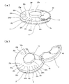
図1(a)(b)は分析用デバイス1の保護キャップ2を閉じた状態と開いた状態を示している。図2は図1(a)における下側を上に向けた状態で分解した状態を示し、図3はその組立図を示している。
An embodiment of an analytical device of the present invention will be described with reference to FIGS.
FIGS. 1A and 1B show a state in which the protective cap 2 of the analysis device 1 is closed and opened. FIG. 2 shows an exploded view with the lower side in FIG. 1 (a) facing upward, and FIG. 3 shows an assembly drawing thereof.

図1と図2に示すようにこの分析用デバイス1は、微細な凹凸形状を表面に有するマイクロチャネル構造が片面に形成されたベース基板3と、ベース基板3の表面を覆うカバー基板4と、希釈液を保持している希釈液容器5と、試料液飛散防止用の保護キャップ2とを合わせた4つの部品で構成されている。   As shown in FIG. 1 and FIG. 2, this analytical device 1 includes a base substrate 3 having a microchannel structure having a fine concavo-convex shape on one surface, a cover substrate 4 covering the surface of the base substrate 3, It is composed of four parts including a diluent container 5 holding a diluent and a protective cap 2 for preventing sample liquid scattering.

ベース基板3とカバー基板4は、希釈液容器5などを内部にセットした状態で接合され、この接合されたものに保護キャップ2が取り付けられている。
ベース基板3の上面に形成されている数個の凹部の開口をカバー基板4で覆うことによって、後述の複数の収容エリア(後述の測定セルと同じ)とその収容エリアの間を接続するマイクロチャネル構造の流路などが形成されている。収容エリアのうちの必要なものには各種の分析に必要な試薬が予め担持されている。保護キャップ2の片側は、ベース基板3とカバー基板4に形成された軸6a,6bに係合して開閉できるように枢支されている。検査しようとする試料液が血液の場合、毛細管力の作用する前記マイクロチャネル構造の各流路の隙間は、50μm〜300μmに設定されている。
The base substrate 3 and the cover substrate 4 are joined with the diluent container 5 and the like set therein, and the protective cap 2 is attached to the joined substrate.
By covering the openings of several concave portions formed on the upper surface of the base substrate 3 with the cover substrate 4, a plurality of storage areas described later (same as measurement cells described later) and the microchannels connecting the storage areas A flow path having a structure is formed. Necessary ones of the storage areas are loaded with reagents necessary for various analyses. One side of the protective cap 2 is pivotally supported so that it can be opened and closed by engaging with the shafts 6 a and 6 b formed on the base substrate 3 and the cover substrate 4. When the sample liquid to be examined is blood, the gap between the flow paths of the microchannel structure on which the capillary force acts is set to 50 μm to 300 μm.

この分析用デバイス1を使用した分析工程の概要は、希釈液が予めセットされた分析用デバイス1に試料液を点着し、この試料液の少なくとも一部を前記希釈液で希釈した後に測定しようとするものである。   The outline of the analysis process using this analytical device 1 is that the sample solution is spotted on the analytical device 1 in which a diluent is set in advance, and at least a part of the sample solution is diluted with the diluent, and then measurement is performed. It is what.

図4は希釈液容器5の形状を示している。
図4(a)は平面図、図4(b)は図4(a)のA−A断面図、図4(c)は側面図、図4(d)は背面図、図4(e)は開口部7から見た正面図である。この開口部7は希釈液容器5の内部5aに、図6(a)に示すように希釈液8を充填した後にシール部材としてのアルミシール9によって密封されている。希釈液容器5の開口部7とは反対側には、ラッチ部10が形成されている。この希釈液容器5は、ベース基板3とカバー基板4の間に形成され希釈液容器収容部11にセットされて図6(a)に示す液保持位置と、図6(c)に示す液放出位置とに移動自在に収容されている。
FIG. 4 shows the shape of the diluent container 5.
4A is a plan view, FIG. 4B is a cross-sectional view taken along line AA of FIG. 4A, FIG. 4C is a side view, FIG. 4D is a rear view, and FIG. These are front views seen from the opening 7. The opening 7 is sealed with an aluminum seal 9 as a seal member after filling the interior 5a of the diluent container 5 with the diluent 8 as shown in FIG. 6 (a). On the opposite side of the diluent container 5 from the opening 7, a latch portion 10 is formed. The dilution liquid container 5 is formed between the base substrate 3 and the cover substrate 4 and is set in the dilution liquid container housing part 11 so that the liquid holding position shown in FIG. 6A and the liquid discharge shown in FIG. It is housed in a freely movable position.

図5は保護キャップ2の形状を示している。
図5(a)は平面図、図5(b)は図5(a)のB−B断面図、図5(c)は側面図、図5(d)は背面図、図5(e)は開口2aから見た正面図である。保護キャップ2の内側には、図1(a)に示した閉塞状態で図6(a)に示すように、希釈液容器5のラッチ部10が係合可能な係止用溝12が形成されている。
FIG. 5 shows the shape of the protective cap 2.
5 (a) is a plan view, FIG. 5 (b) is a cross-sectional view taken along line BB of FIG. 5 (a), FIG. 5 (c) is a side view, FIG. 5 (d) is a rear view, and FIG. These are the front views seen from the opening 2a. As shown in FIG. 6 (a) in the closed state shown in FIG. 1 (a), a locking groove 12 with which the latch portion 10 of the diluent container 5 can be engaged is formed inside the protective cap 2. ing.

この図6(a)は使用前の分析用デバイス1を示す。この状態では保護キャップ2が閉塞されており、保護キャップ2の係止用溝12に希釈液容器5のラッチ部10が係合して希釈液容器5が矢印J方向に移動しないように液保持位置に係止されている。この状態で利用者に供給される。   FIG. 6A shows the analysis device 1 before use. In this state, the protective cap 2 is closed, and the latch portion 10 of the diluent container 5 is engaged with the locking groove 12 of the protective cap 2 so as to prevent the diluent container 5 from moving in the arrow J direction. Locked in position. In this state, it is supplied to the user.

試料液の点着に際して保護キャップ2が図6(a)でのラッチ部10との係合に抗して図1(b)に示したように開かれると、保護キャップ2の係止用溝12が形成されている底部2bが弾性変形して図6(b)に示すように保護キャップ2の係止用溝12と希釈液容器5のラッチ部10との係合が解除される。   When the protective cap 2 is opened as shown in FIG. 1B against the engagement with the latch portion 10 in FIG. 6A when the sample liquid is spotted, the locking groove of the protective cap 2 As shown in FIG. 6 (b), the bottom portion 2b formed with 12 is elastically deformed, and the engagement between the locking groove 12 of the protective cap 2 and the latch portion 10 of the diluent container 5 is released.

この状態で、分析用デバイス1の露出した注入口13に試料液を点着して保護キャップ2を閉じる。この際、保護キャップ2を閉じることによって、係止用溝12を形成していた壁面12aが、希釈液容器5のラッチ部10の保護キャップ2の側の面5bに当接して、希釈液容器5を前記矢印J方向(液放出位置に近づく方向)に押し込む。希釈液容器収容部11には、ベース基板3の側から突出部としての開封リブ14が形成されており、希釈液容器5が保護キャップ2によって押し込まれると、希釈液容器5の斜めに傾斜した開口部7のシール面に張られていたアルミシール9が図6(c)に示すように開封リブ14に衝突して破られる。   In this state, the sample solution is spotted on the exposed inlet 13 of the analytical device 1 and the protective cap 2 is closed. At this time, by closing the protective cap 2, the wall surface 12 a forming the locking groove 12 comes into contact with the surface 5 b on the side of the protective cap 2 of the latch portion 10 of the diluent container 5, so that the diluent container 5 is pushed in the direction of arrow J (direction approaching the liquid discharge position). An opening rib 14 as a protruding portion is formed in the diluent container housing portion 11 from the base substrate 3 side, and when the diluent container 5 is pushed in by the protective cap 2, the diluent container 5 is inclined obliquely. The aluminum seal 9 stretched on the sealing surface of the opening 7 collides with the opening rib 14 and is broken as shown in FIG.

なお、図7は分析用デバイス1を図6(a)に示した出荷状態にセットする製造工程を示している。先ず、保護キャップ2を閉じる前に、希釈液容器5の下面に設けた溝42(図2と図4(d)参照)と、カバー基板4に設けた孔43とを位置合わせして、この液保持位置において孔43を通して希釈液容器5の溝42に、ベース基板3またはカバー基板4とは別に設けられた係止治具44の突起44aを係合させて、希釈液容器5を液保持位置に係止した状態にセットする。そして、保護キャップ2の上面に形成されている切り欠き45(図1参照)から、押圧治具46を差し入れて保護キャップ2の底面を押圧して弾性変形させた状態で保護キャップ2を閉じてから押圧治具46を解除することによって、図6(a)の状態にセットできる。   FIG. 7 shows a manufacturing process in which the analysis device 1 is set in the shipping state shown in FIG. First, before closing the protective cap 2, the groove 42 (see FIGS. 2 and 4 (d)) provided in the lower surface of the diluent container 5 and the hole 43 provided in the cover substrate 4 are aligned, At the liquid holding position, the protrusion 42a of the locking jig 44 provided separately from the base substrate 3 or the cover substrate 4 is engaged with the groove 42 of the diluent container 5 through the hole 43 to hold the diluent container 5 with the liquid. Set in a locked state. Then, the protective cap 2 is closed in a state where the pressing jig 46 is inserted from the notch 45 (see FIG. 1) formed on the upper surface of the protective cap 2 and the bottom surface of the protective cap 2 is pressed and elastically deformed. Can be set to the state shown in FIG. 6A by releasing the pressing jig 46.

なお、この実施の形態では希釈液容器5の下面に溝42を設けた場合を例に挙げて説明したが、希釈液容器5の上面に溝42を設け、この溝42に対応してベース基板3に孔43を設けて係止治具44の突起44aを溝42に係合させるようにも構成できる。   In this embodiment, the case where the groove 42 is provided on the lower surface of the diluent container 5 has been described as an example. However, the groove 42 is provided on the upper surface of the diluent container 5, and the base substrate corresponds to the groove 42. 3 can be configured such that a hole 43 is provided in the groove 3 and the protrusion 44 a of the locking jig 44 is engaged with the groove 42.

また、保護キャップ2の係止用溝12が希釈液容器5のラッチ部10に直接に係合して希釈液容器5を液保持位置に係止したが、保護キャップ2の係止用溝12と希釈液容器5のラッチ部10とを間接的に係合させて希釈液容器5を液保持位置に係止することもできる。   Further, the locking groove 12 of the protective cap 2 directly engages the latch portion 10 of the diluent container 5 to lock the diluent container 5 in the liquid holding position. And the latch portion 10 of the diluent container 5 can be indirectly engaged to lock the diluent container 5 in the liquid holding position.

この分析用デバイス1を図8と図9に示すように、カバー基板4を下側にして分析装置100のロータ101にセットすることで、試料液の成分分析を行うことができる。
ロータ101の上面には溝102が形成されており、分析用デバイス1をロータ101にセットした状態では分析用デバイス1のカバー基板4に形成された回転支持部15と保護キャップ2に形成された回転支持部16が溝102に係合してこれを収容している。
As shown in FIGS. 8 and 9, the analysis device 1 is set on the rotor 101 of the analyzer 100 with the cover substrate 4 facing downward, so that the component analysis of the sample solution can be performed.
A groove 102 is formed on the upper surface of the rotor 101. When the analysis device 1 is set on the rotor 101, the groove 102 is formed on the rotation support 15 and the protective cap 2 formed on the cover substrate 4 of the analysis device 1. The rotation support portion 16 engages with and accommodates the groove 102.

ロータ101に分析用デバイス1をセットした後に、ロータ101の回転させる前に分析装置のドア103を閉じると、セットされた分析用デバイス1は、ドア103の側に設けられた可動片104によって、ロータ101の回転軸心上の位置がバネ105の付勢力でロータ101の側に押さえられて、分析用デバイス1は、回転駆動手段106によって回転駆動されるロータ101と一体に回転する。107はロータ101の回転中の軸心を示している。保護キャップ2は注入口13の付近に付着した試料液が、分析中に遠心力によって外部へ飛散を防止するために取り付けられている。   When the analysis device 1 is set on the rotor 101 and the door 103 of the analyzer is closed before the rotor 101 is rotated, the set analysis device 1 is moved by the movable piece 104 provided on the door 103 side. The position on the rotational axis of the rotor 101 is pressed against the rotor 101 by the biasing force of the spring 105, and the analysis device 1 rotates integrally with the rotor 101 that is rotationally driven by the rotational driving means 106. Reference numeral 107 denotes an axial center during rotation of the rotor 101. The protective cap 2 is attached in order to prevent the sample liquid adhering to the vicinity of the inlet 13 from being scattered outside due to centrifugal force during analysis.

分析用デバイス1を構成する部品の材料としては、材料コストが安価で量産性に優れる樹脂材料が望ましい。前記分析装置100は、分析用デバイス1を透過した光を測定する光学的測定方法によって試料液の分析を行うため、ベース基板3およびカバー基板4の材料としては、PC,PMMA,AS,MSなどの透明性が高い合成樹脂が望ましい。   As a material of the parts constituting the analysis device 1, a resin material having a low material cost and excellent mass productivity is desirable. Since the analysis apparatus 100 analyzes the sample liquid by an optical measurement method for measuring light transmitted through the analysis device 1, the material of the base substrate 3 and the cover substrate 4 may be PC, PMMA, AS, MS, or the like. A synthetic resin having high transparency is desirable.

また、希釈液容器5の材料としては、希釈液容器5内部に希釈液8を長期間封入しておく必要があるため、PP,PEなどの水分透過率の低い結晶性の合成樹脂が望ましい。保護キャップ2の材料としては、成形性のよい材料であれば特に問題がなく、PP,PEなどの安価な樹脂が望ましい。   Further, as the material of the diluent container 5, since it is necessary to enclose the diluent 8 in the diluent container 5 for a long period of time, a crystalline synthetic resin having a low moisture permeability such as PP and PE is desirable. As a material for the protective cap 2, there is no particular problem as long as it is a material with good moldability, and an inexpensive resin such as PP or PE is desirable.

ベース基板3とカバー基板4との接合は、前記収容エリアに担持された試薬の反応活性に影響を与えにくい方法が望ましく、接合時に反応性のガスや溶剤が発生しにくい超音波溶着やレーザー溶着などが望ましい。   The base substrate 3 and the cover substrate 4 are preferably joined by a method that hardly affects the reaction activity of the reagent carried in the storage area. Ultrasonic welding or laser welding is less likely to generate reactive gas or solvent during joining. Etc. are desirable.

また、ベース基板3とカバー基板4との接合によって両基板3,4の間の微小な隙間による毛細管力によって溶液を移送させる部分には、毛細管力を高めるための親水処理がなされている。具体的には、親水性ポリマーや界面活性剤などを用いた親水処理が行われている。ここで、親水性とは水との接触角が90°未満のことをいい、より好ましくは接触角40°未満である。   Further, a hydrophilic treatment for increasing the capillary force is applied to the portion where the solution is transferred by the capillary force due to the minute gap between the substrates 3 and 4 by joining the base substrate 3 and the cover substrate 4. Specifically, hydrophilic treatment using a hydrophilic polymer or a surfactant is performed. Here, hydrophilic means that the contact angle with water is less than 90 °, more preferably less than 40 °.

図10は分析装置100の構成を示す。
この分析装置100は、ロータ101を回転させるための回転駆動手段106と、分析用デバイス1内の反応物にアクセスして分析する分析手段としての光学測定部108と、ロータ101の回転速度や回転方向および光学測定部108の測定タイミングなどを制御する制御手段109と、光学測定部108によって得られた信号を処理し測定結果を演算するための演算部110と、演算部110で得られた結果を表示するための表示部111とで構成されている。
FIG. 10 shows the configuration of the analyzer 100.
The analysis apparatus 100 includes a rotation driving unit 106 for rotating the rotor 101, an optical measurement unit 108 as an analysis unit that accesses and analyzes the reactant in the analysis device 1, and the rotation speed and rotation of the rotor 101. Control means 109 for controlling the direction and measurement timing of the optical measurement unit 108, a calculation unit 110 for processing a signal obtained by the optical measurement unit 108 and calculating a measurement result, and a result obtained by the calculation unit 110 It is comprised with the display part 111 for displaying.

回転駆動手段106は、ロータ101を介して分析用デバイス1を回転軸心107の回りに任意の方向に所定の回転速度で回転させるだけではなく、所定の停止位置で回転軸心107を中心に所定の振幅範囲、周期で左右に往復運動をさせて分析用デバイス1を揺動させることができるように構成されている。   The rotation driving means 106 not only rotates the analyzing device 1 around the rotation axis 107 at a predetermined rotation speed around the rotation axis 107 via the rotor 101 but also centers on the rotation axis 107 at a predetermined stop position. The analyzing device 1 can be swung by reciprocating left and right in a predetermined amplitude range and cycle.

光学測定部108には、分析用デバイス1の測定セルに光を照射する光源112aと、光源112aから照射された光のうち、分析用デバイス1を通過した透過光の光量を検出するフォトディテクタ113aと、分析用デバイス1の測定セルとは別の測定部に光を照射する光源112bと、光源112bから照射された光のうち、分析用デバイス1を通過した透過光の光量を検出するフォトディテクタ113bとを備えている。   The optical measurement unit 108 includes a light source 112a that emits light to the measurement cell of the analysis device 1, and a photodetector 113a that detects the amount of transmitted light that has passed through the analysis device 1 out of the light emitted from the light source 112a. A light source 112b for irradiating light to a measurement unit different from the measurement cell of the analytical device 1, and a photodetector 113b for detecting the amount of transmitted light that has passed through the analytical device 1 out of the light emitted from the light source 112b, It has.

分析用デバイス1をロータ101によって回転駆動して、注入口13から内部に取り込んだ試料液を、注入口13よりも内周にある前記回転軸心107を中心に分析用デバイス1を回転させて発生する遠心力と、分析用デバイス1内に設けられた毛細管流路の毛細管力を用いて、分析用デバイス1の内部で溶液を移送していくよう構成されており、分析用デバイス1のマイクロチャネル構造を分析工程とともに詳しく説明する。   The analysis device 1 is driven to rotate by the rotor 101, and the sample liquid taken into the inside from the injection port 13 is rotated around the rotation axis 107 located on the inner periphery of the injection port 13. The centrifugal force generated and the capillary force of the capillary channel provided in the analysis device 1 are used to transfer the solution inside the analysis device 1. The channel structure will be described in detail along with the analysis process.

図11は分析用デバイス1の注入口13の付近を示している。
図11(a)は注入口13を分析用デバイス1の外側から見た拡大図を示し、図11(b)は前記マイクロチャネル構造をロータ101の側からカバー基板4を透過して見たものである。
FIG. 11 shows the vicinity of the inlet 13 of the analytical device 1.
FIG. 11A shows an enlarged view of the injection port 13 viewed from the outside of the analytical device 1, and FIG. 11B shows the microchannel structure viewed through the cover substrate 4 from the rotor 101 side. It is.

注入口13は、ベース基板3とカバー基板4との間に形成された微小な隙間δの毛細管力の作用する誘導部17を介して、この誘導部17と同様に毛細管力の作用する隙間で必要量の試料液18を保持できる容積の毛細管キャビティ19と接続されている。誘導部17の流れ方向と直交する断面形状(図11(b)のD−D断面)は、奥側が垂直な矩形形ではなくて、図11(c)に示すように奥端ほどカバー基板4に向かって次第に狭くなる傾斜面20で形成されている。誘導部17と毛細管キャビティ19と接続部にはベース基板3に凹部21を形成して通路の向きを変更する屈曲部22が形成されている。   The inlet 13 is a gap where a capillary force acts like the guiding part 17 via a guiding part 17 where a capillary force acts in a minute gap δ formed between the base substrate 3 and the cover substrate 4. A capillary cavity 19 having a volume capable of holding a required amount of sample liquid 18 is connected. The cross-sectional shape orthogonal to the flow direction of the guide portion 17 (the DD cross section in FIG. 11B) is not a rectangular shape with the back side vertical, but as shown in FIG. It forms in the inclined surface 20 which becomes narrow gradually toward. The guide portion 17, the capillary cavity 19, and the connection portion are formed with a bent portion 22 that forms a recess 21 in the base substrate 3 and changes the direction of the passage.

誘導部17から見て毛細管キャビティ19を介してその先には、毛細管力が作用しない隙間の試料液受容キャビティ23が形成されている。毛細管キャビティ19と屈曲部22および誘導部17の一部の側方には、一端が試料液受容キャビティ23に接続され、他端が大気に開放したキャビティ24が形成されている。   A sample liquid receiving cavity 23 is formed at the tip of the capillary cavity 19 as viewed from the guiding portion 17 so that a gap between which the capillary force does not act is formed. A cavity 24 having one end connected to the sample solution receiving cavity 23 and the other end opened to the atmosphere is formed on a side of a part of the capillary cavity 19, the bent portion 22, and the guiding portion 17.

このように構成したため、試料液18として血液を注入口13に点着すると、試料液18は誘導部17を介して毛細管キャビティ19まで取り込まれる。図12はこのようにして点着後の分析用デバイス1をロータ101にセットして回転させる前の状態を示している。このとき、図6(c)で説明したように希釈液容器5のアルミシール9が開封リブ14に衝突して破られている。25a〜25g,25h,25i1,25i2,25j〜25nはベース基板3に形成された空気孔である。   With this configuration, when blood is spotted on the inlet 13 as the sample solution 18, the sample solution 18 is taken up to the capillary cavity 19 via the guide portion 17. FIG. 12 shows a state before the analysis device 1 after spotting is set on the rotor 101 and rotated. At this time, as explained in FIG. 6C, the aluminum seal 9 of the diluent container 5 collides with the opening rib 14 and is broken. Reference numerals 25a to 25g, 25h, 25i1, 25i2, and 25j to 25n denote air holes formed in the base substrate 3.

分析工程を、回転駆動手段106の運転を制御している制御手段109の構成と共に説明する。
− 工程1 −
検査を受ける試料液が注入口13に点着された分析用デバイス1は、図13(a)に示すように毛細管キャビティ19内に試料液を保持し、希釈液容器5のアルミシール9が破られた状態でロータ101にセットされる。
The analysis process will be described together with the configuration of the control means 109 that controls the operation of the rotation drive means 106.
− Step 1 −
The analytical device 1 in which the sample liquid to be inspected is spotted on the inlet 13 holds the sample liquid in the capillary cavity 19 as shown in FIG. 13A, and the aluminum seal 9 of the diluent container 5 is broken. In this state, the rotor 101 is set.

− 工程2 −
ドア103を閉じた後にロータ101を時計方向(C2方向)に回転駆動すると、保持されている試料液が屈曲部22の位置で破断し、誘導部17内の試料液は保護キャップ2内に排出され、毛細管キャビティ19内の試料液18は図13(b)に示すように試料液受容キャビティ23に流入し保持される。
− Step 2 −
When the rotor 101 is rotationally driven in the clockwise direction (C2 direction) after the door 103 is closed, the held sample solution is broken at the position of the bent portion 22, and the sample solution in the guide portion 17 is discharged into the protective cap 2. Then, the sample liquid 18 in the capillary cavity 19 flows into the sample liquid receiving cavity 23 and is held as shown in FIG.

希釈液容器5から流出した希釈液8は、排出流路26を介して保持キャビティ27に流入する。保持キャビティ27に流入した希釈液8が所定量を超えると、超えた希釈液8は溢流流路28を介して図13(b)に示すように混合キャビティ29に流れ込み、さらに混合キャビティ29に流入した希釈液8が所定量を超えると、超えた希釈液8は連結流路34a,34bおよび溢流流路38を介して溢流キャビティ36a,36b,36c,36dに流れ込む。溢流キャビティ36a,36b,36cに流入した希釈液8は逆流防止流路35a,35bの毛細管力によって溢流キャビティ36a,36b,36cから流出しないように保持される。   The diluent 8 that has flowed out of the diluent container 5 flows into the holding cavity 27 via the discharge channel 26. When the dilution liquid 8 flowing into the holding cavity 27 exceeds a predetermined amount, the excess dilution liquid 8 flows into the mixing cavity 29 as shown in FIG. When the inflowing diluent 8 exceeds a predetermined amount, the excess diluent 8 flows into the overflow cavities 36a, 36b, 36c, and 36d via the connection channels 34a and 34b and the overflow channel 38. The diluent 8 that has flowed into the overflow cavities 36a, 36b, 36c is held so as not to flow out of the overflow cavities 36a, 36b, 36c by the capillary force of the backflow prevention flow paths 35a, 35b.

ここで、希釈液8は特定の波長域で規定の吸光度を有する溶液であり、混合キャビティ29に流入した希釈液8が混合キャビティ29に滞在している間に、希釈液8の吸光度が測定(一次測光)される。具体的には、分析用デバイス1を時計方向(C2方向)に回転駆動して、希釈液8の入った混合キャビティ29が光源112bとフォトディテクタ113bの間を通過するタイミングに、演算部110がフォトディテクタ113bの検出値を読み取る。   Here, the diluent 8 is a solution having a prescribed absorbance in a specific wavelength region, and the absorbance of the diluent 8 is measured while the diluent 8 flowing into the mixing cavity 29 stays in the mixing cavity 29 ( Primary metering). Specifically, when the analyzing device 1 is rotationally driven in the clockwise direction (C2 direction) and the mixing cavity 29 containing the diluent 8 passes between the light source 112b and the photodetector 113b, the calculation unit 110 detects the photodetector. The detection value 113b is read.

連結流路34aは混合キャビティ29の最外周部から内周方向に屈曲部をもつサイホン構造を有しており、連結流路34aの屈曲部を超える希釈液8が流入してくると、サイホン効果によって混合キャビティ29内の希釈液8が溢流キャビティ36a,36b,36cに排出される。また、連結流路34aのさらに内周位置に所定量を超えた希釈液を排出するための連結流路34bを設けることで、過剰な希釈液が流入した際に混合キャビティ29から試料液受容キャビティ23へ流入するのを防いでいる。   The connection channel 34a has a siphon structure having a bent portion in the inner circumferential direction from the outermost peripheral portion of the mixing cavity 29, and when the diluent 8 exceeding the bent portion of the connection channel 34a flows in, the siphon effect As a result, the diluent 8 in the mixing cavity 29 is discharged into the overflow cavities 36a, 36b, 36c. Further, by providing a connecting channel 34b for discharging a diluent exceeding a predetermined amount at an inner peripheral position of the connecting channel 34a, a sample solution receiving cavity is supplied from the mixing cavity 29 when an excessive diluent flows. Inflow to 23 is prevented.

混合キャビティ29に滞在していた希釈液8は、時間の経過と共に溢流キャビティ36a,36b,36cにすべて排出されて、図14(a)に示すように試料液受容キャビティ23と、保持キャビティ27にそれぞれ所定量の試料液18と希釈液8が保持された状態になる。   The diluent 8 staying in the mixing cavity 29 is discharged to the overflow cavities 36a, 36b, 36c as time passes, and the sample liquid receiving cavity 23 and the holding cavity 27 as shown in FIG. A predetermined amount of the sample solution 18 and the diluted solution 8 are held.

なお、希釈液容器5は、アルミシール9でシールされている開口部7とは反対側の底部の形状が、図4(a)(b)に示すように円弧面32で形成され、かつ図13(b)に示す状態の希釈液容器5の液放出位置においては、図15に示すように円弧面32の中心mが回転軸心107よりも排出流路26側に近づくよう距離dだけオフセットするように形成されているため、この円弧面32に向かうように流れた希釈液8が円弧面32に沿って外側から開口部7に向かう流れ(矢印n方向)に変更されて、希釈液容器5の開口部7から効率よく希釈液容器収容部11に放出される。   The diluent container 5 has a bottom portion opposite to the opening 7 sealed with the aluminum seal 9 and is formed with an arcuate surface 32 as shown in FIGS. 4 (a) and 4 (b). At the liquid discharge position of the diluent container 5 in the state shown in FIG. 13B, as shown in FIG. 15, the center m of the arc surface 32 is offset by a distance d so as to be closer to the discharge flow path 26 side than the rotation axis 107. Therefore, the diluent 8 that has flowed toward the arc surface 32 is changed to a flow (in the direction of arrow n) from the outside toward the opening 7 along the arc surface 32, so that the diluent container 5 is efficiently discharged from the opening 7 to the diluent container housing 11.

− 工程3 −
次に、ロータ101の回転を停止させると、試料液18は図14(b)に示すように試料液受容キャビティ23と混合キャビティ29を連結しているサイホン形状を有する連結流路30に呼び水され、同様に、希釈液8も保持キャビティ27と混合キャビティ29を連結しているサイホン形状を有する連結流路41に呼び水される。
− Step 3 −
Next, when the rotation of the rotor 101 is stopped, the sample liquid 18 is primed into the connection channel 30 having a siphon shape connecting the sample liquid receiving cavity 23 and the mixing cavity 29 as shown in FIG. Similarly, the diluting liquid 8 is also primed into the connection channel 41 having a siphon shape connecting the holding cavity 27 and the mixing cavity 29.

− 工程4 −
ロータ101を反時計方向(C1方向)に回転駆動すると、試料液受容キャビティ23の試料液18と保持キャビティ27の希釈液8は図16(a)に示すように混合キャビティ29に流入するとともに、混合キャビティ29で希釈血漿成分18aと血球成分18bとに遠心分離される。18cは希釈血漿成分18aと血球成分18bとの分離界面を表している。ここで、試料液18と希釈液8はリブ31に一旦衝突してから混合キャビティ29に流入させるので、試料液18中の血漿成分と希釈液8とを均一に攪拌できる。
− Step 4 −
When the rotor 101 is driven to rotate counterclockwise (C1 direction), the sample liquid 18 in the sample liquid receiving cavity 23 and the diluted liquid 8 in the holding cavity 27 flow into the mixing cavity 29 as shown in FIG. In the mixing cavity 29, it is centrifuged into a diluted plasma component 18a and a blood cell component 18b. Reference numeral 18c represents a separation interface between the diluted plasma component 18a and the blood cell component 18b. Here, since the sample solution 18 and the diluent 8 once collide with the rib 31 and then flow into the mixing cavity 29, the plasma component in the sample solution 18 and the diluent 8 can be uniformly stirred.

そして、混合キャビティ29で遠心分離された希釈血漿成分18aの吸光度が測定(二次測光)される。具体的には、分析用デバイス1を反時計方向(C1方向)に回転駆動して、希釈血漿成分18aの入った混合キャビティ29が光源112bとフォトディテクタ113bの間を通過するタイミングに、演算部110がフォトディテクタ113bの検出値を読み取る。   Then, the absorbance of the diluted plasma component 18a centrifuged in the mixing cavity 29 is measured (secondary photometry). Specifically, the analyzing device 1 is rotationally driven counterclockwise (C1 direction), and at the timing when the mixing cavity 29 containing the diluted plasma component 18a passes between the light source 112b and the photodetector 113b, the calculation unit 110 Reads the detection value of the photodetector 113b.

ここで、この実施の形態では、試料液18である血液と希釈液8を直接に混合してから希釈血漿成分18aを抽出し、試薬と反応させて血漿成分中の特定成分を分析する構成としているが、血液中の血漿成分の割合は個人差があるため、直接に混合した際に血漿成分の希釈倍率が大きくばらつく。そのため、希釈血漿成分18aと試薬を反応させた際に反応濃度がばらついて測定精度に影響を与えてしまう。そのため、試料液18と希釈液8とを混合した時の希釈倍率のばらつきを補正するために、特定の波長域で規定の吸光度を有する希釈液を用いて、試料液との混合前後の吸光度を、混合キャビティ29の同一箇所にて測定して希釈倍率を算出しているため、測定部の光路長ばらつきを除くことができ、精度のよい希釈倍率の測定ができるとともに、測定セルにおける測定結果に対して、希釈倍率のばらつきを補正することができ測定精度が大幅に改善される。また、この補正方法は試料液18と希釈液8の液量ばらつきによる希釈倍率のばらつき補正にも有用である。   Here, in this embodiment, the blood that is the sample liquid 18 and the diluent 8 are directly mixed and then the diluted plasma component 18a is extracted and reacted with a reagent to analyze a specific component in the plasma component. However, since the ratio of the plasma component in the blood varies among individuals, the dilution ratio of the plasma component varies greatly when directly mixed. Therefore, when the diluted plasma component 18a is reacted with the reagent, the reaction concentration varies and affects the measurement accuracy. Therefore, in order to correct the dispersion of the dilution ratio when the sample solution 18 and the diluent 8 are mixed, the absorbance before and after mixing with the sample solution is measured using a diluent having a specified absorbance in a specific wavelength region. Since the dilution factor is calculated by measuring at the same location of the mixing cavity 29, the variation in the optical path length of the measurement unit can be eliminated, the measurement of the dilution factor with high accuracy can be performed, and the measurement result in the measurement cell On the other hand, variations in dilution ratio can be corrected, and the measurement accuracy is greatly improved. This correction method is also useful for correcting variation in the dilution factor due to variations in the liquid volume of the sample liquid 18 and the diluent 8.

− 工程5 −
次に、ロータ101の回転を停止させると、希釈血漿成分18aは、混合キャビティ29の壁面に形成された毛細管キャビティ33に吸い上げられ、毛細管キャビティ33と連通する毛細管流路37を介して図16(b)に示すように溢流流路38,計量流路39a,39b,39c,39d,39e,39f,39gに流れて、計量流路39a〜39gに定量が保持される。
− Step 5 −
Next, when the rotation of the rotor 101 is stopped, the diluted plasma component 18 a is sucked up into the capillary cavity 33 formed on the wall surface of the mixing cavity 29, and is passed through the capillary channel 37 communicating with the capillary cavity 33 as shown in FIG. As shown in b), it flows into the overflow channel 38, the metering channels 39a, 39b, 39c, 39d, 39e, 39f, and 39g, and the fixed amount is held in the metering channels 39a to 39g.

なお、図17(a)に毛細管キャビティ33とその周辺の斜視図を示す。図17(a)におけるE−E断面を図17(b)に示す。この毛細管キャビティ33とその周辺を詳しく説明する。   FIG. 17A shows a perspective view of the capillary cavity 33 and its periphery. The EE cross section in Fig.17 (a) is shown in FIG.17 (b). The capillary cavity 33 and its periphery will be described in detail.

毛細管キャビティ33は、混合キャビティ29の底部29bから内周側に向かって形成されている。換言すると、毛細管キャビティ33の最外周の位置は、図16(a)に示す希釈血漿成分18aと血球成分18bとの分離界面18cよりも外周方向に伸長して形成されている。このように毛細管キャビティ33の外周側の位置を上記のように設定することによって、毛細管キャビティ33の外周端が、混合キャビティ29において分離された希釈血漿成分18aと血球成分18bに浸かっており、希釈血漿成分18aは血球成分18bに比べて粘度が低いため、希釈血漿成分18aの方が優先的に毛細管キャビティ33によって吸い出され、毛細管流路37と溢流流路38、計量流路39a,39b,39c,39d,39e,39f,39gを介して測定セル40a〜40f,40gに向かって希釈血漿成分18aを移送できる。   The capillary cavity 33 is formed from the bottom 29 b of the mixing cavity 29 toward the inner peripheral side. In other words, the outermost peripheral position of the capillary cavity 33 is formed to extend in the outer peripheral direction from the separation interface 18c between the diluted plasma component 18a and the blood cell component 18b shown in FIG. Thus, by setting the outer peripheral side position of the capillary cavity 33 as described above, the outer peripheral end of the capillary cavity 33 is immersed in the diluted plasma component 18a and the blood cell component 18b separated in the mixing cavity 29. Since the plasma component 18a has a lower viscosity than the blood cell component 18b, the diluted plasma component 18a is preferentially sucked out by the capillary cavity 33, and the capillary channel 37, the overflow channel 38, and the metering channels 39a, 39b. , 39c, 39d, 39e, 39f, and 39g, the diluted plasma component 18a can be transferred toward the measurement cells 40a to 40f and 40g.

また、希釈血漿成分18aが吸い出された後、血球成分18bも希釈血漿成分18aの後を追って吸い出されるため、毛細管キャビティ33および毛細管流路37の途中までの経路を血球成分18bで置換することができ、溢流流路38および計量流路39a〜39gが希釈血漿成分18aで満たされると、毛細管流路37および毛細管キャビティ33内の液の移送も止まるため、溢流流路38および計量流路39a〜39gに血球成分18bが混入することはない。   In addition, since the blood cell component 18b is also sucked after the diluted plasma component 18a after the diluted plasma component 18a is sucked out, the path to the middle of the capillary cavity 33 and the capillary channel 37 is replaced with the blood cell component 18b. When the overflow channel 38 and the metering channels 39a to 39g are filled with the diluted plasma component 18a, the transfer of the liquid in the capillary channel 37 and the capillary cavity 33 is stopped. The blood cell component 18b is not mixed into the flow paths 39a to 39g.

したがって、従来の構成よりも送液ロスを最小限に抑えることができるため、測定に必要な試料液の量を低減することができる。
− 工程6 −
更に、ロータ101を反時計方向(C1方向)に回転駆動すると、図18(a)に示すように、計量流路39a〜39gに保持されていた希釈血漿成分18aは、大気と連通する大気開放キャビティ48との連結部である屈曲部49a,49b,49c,49d,49e,49f,49gの位置で破断して測定セル40a〜40f,40gに流れ込む。ここでは測定セル40a〜40fのそれぞれに同じ量の希釈血漿成分18aが流れ込む。
Therefore, since the liquid feeding loss can be minimized as compared with the conventional configuration, the amount of the sample liquid necessary for the measurement can be reduced.
-Step 6-
Further, when the rotor 101 is rotationally driven in the counterclockwise direction (C1 direction), as shown in FIG. 18A, the diluted plasma component 18a held in the measurement flow paths 39a to 39g is released into the atmosphere. It breaks at the positions of the bent portions 49a, 49b, 49c, 49d, 49e, 49f, and 49g, which are connected to the cavity 48, and flows into the measurement cells 40a to 40f and 40g. Here, the same amount of diluted plasma component 18a flows into each of the measurement cells 40a to 40f.

また、このとき溢流流路38の希釈血漿成分18aは、溢流キャビティ36dと逆流防止通路35bを介して溢流キャビティ36c,36aに流れ込む。また、このとき混合キャビティ29内の試料液は、サイホン形状の連結流路34aと溢流キャビティ36bを介して溢流キャビティ36a,36cに流れ込む。   At this time, the diluted plasma component 18a in the overflow channel 38 flows into the overflow cavities 36c and 36a via the overflow cavity 36d and the backflow prevention passage 35b. At this time, the sample liquid in the mixing cavity 29 flows into the overflow cavities 36a and 36c via the siphon-shaped connection channel 34a and the overflow cavity 36b.

測定セル40a〜40f,40gの形状は、遠心力の働く方向に伸長した形状で、具体的には、分析用デバイス1の回転中心から最外周に向かって分析用デバイス1の周方向の幅が細く形成されている。複数の測定セル40a〜40f,40gの外周側の底部は分析用デバイス1の同一半径上に配置されているため、複数の測定セル40a〜40f,40gを測定するのに同一波長の光源112aやそれに対応するフォトディテクタ113aを別の半径距離に複数個配置する必要が無く、装置のコストを削減できると共に、同一測定セル内に複数の異なる波長を用いて測定することもできるため、混合溶液の濃度に応じて最適な波長を選択することで測定感度を向上させることができる。   The shape of the measurement cells 40a to 40f and 40g is a shape extended in the direction in which the centrifugal force acts. Specifically, the width in the circumferential direction of the analysis device 1 from the center of rotation of the analysis device 1 toward the outermost periphery. It is thin. Since the bottoms on the outer peripheral side of the plurality of measurement cells 40a to 40f and 40g are arranged on the same radius of the analyzing device 1, the light source 112a having the same wavelength is used to measure the plurality of measurement cells 40a to 40f and 40g. Since it is not necessary to arrange a plurality of corresponding photodetectors 113a at different radial distances, the cost of the apparatus can be reduced, and measurement can be performed using a plurality of different wavelengths in the same measurement cell. The measurement sensitivity can be improved by selecting the optimum wavelength according to the above.

さらに、各測定セル40a,40b,40d〜40fの周方向に位置する側壁の一側壁には、前記測定セルの外周位置から内周方向に伸長するように毛細管エリア47a,47b,47d,47e,47fが形成されている。図18(a)におけるF−F断面を図20(a)に示す。   Further, on one side wall of each measurement cell 40a, 40b, 40d to 40f in the circumferential direction, capillary areas 47a, 47b, 47d, 47e, and so on extend from the outer peripheral position of the measurement cell in the inner peripheral direction. 47f is formed. The FF cross section in Fig.18 (a) is shown to Fig.20 (a).

また、測定セル40cの周方向に位置する側壁の両側壁には、前記測定セルの外周位置から内周方向に伸長するように毛細管エリア47c1,47c2が形成されている。図18(a)におけるG−G断面を図20(b)に示す。   Capillary areas 47c1 and 47c2 are formed on both side walls of the measurement cell 40c in the circumferential direction so as to extend in the inner circumferential direction from the outer circumferential position of the measurement cell. FIG. 20B shows a GG cross section in FIG.

なお、測定セル40gには測定セル40a〜40fに見られたような毛細管エリアは形成されていない。
毛細管エリア47aの吸い上げ可能な容量は、測定セル40aに保持される試料液を全て収容できる容量よりも少ない容量に形成されている。毛細管エリア47b,47d〜47fも同様に、それぞれの測定セル40b,40d〜40fに保持される試料液を全て収容できる容量よりも少ない容量に形成されている。測定セル40cの毛細管エリア47c1,47c2については、毛細管エリア47c1の吸い上げ可能な容量と毛細管エリア47c2の吸い上げ可能な容量との加算値が、測定セル40cに保持される試料液を全て収容できる容量に形成されている。測定セル40b〜40f,40gの光路長は互いに同じ長さに形成されている。
Note that the capillary area as seen in the measurement cells 40a to 40f is not formed in the measurement cell 40g.
The capacitable capacity of the capillary area 47a is formed to be smaller than the capacity capable of accommodating all the sample liquid held in the measurement cell 40a. Similarly, the capillary areas 47b and 47d to 47f are formed to have a capacity smaller than the capacity capable of accommodating all the sample liquids held in the respective measurement cells 40b and 40d to 40f. For the capillary areas 47c1 and 47c2 of the measurement cell 40c, the sum of the capacity that can be sucked up by the capillary area 47c1 and the capacity that can be sucked up by the capillary area 47c2 is a capacity that can accommodate all the sample liquid held in the measurement cell 40c. Is formed. The optical path lengths of the measurement cells 40b to 40f and 40g are formed to be the same length.

また、図19に示すように毛細管エリア47a,47b,47c1,47c2,47d,47e,47fには、試料液と反応させる試薬T1が担持されている。測定セル40gには試薬が設けられていない。毛細管エリア47a,47b,47c1,47c2,47d〜47fに担持させた試薬T1は、分析する特定成分に応じて異なっており、溶けやすい試薬を毛細管エリア47a,47b,47d〜47fに担持させ、毛細管エリア47c1,47c2には溶けにくい試薬を担持させる。   Further, as shown in FIG. 19, the capillary areas 47a, 47b, 47c1, 47c2, 47d, 47e, and 47f carry a reagent T1 that reacts with the sample solution. No reagent is provided in the measurement cell 40g. The reagent T1 carried in the capillary areas 47a, 47b, 47c1, 47c2, 47d to 47f differs depending on the specific component to be analyzed, and the easily soluble reagent is carried on the capillary areas 47a, 47b, 47d to 47f. In the areas 47c1 and 47c2, a difficult-to-dissolve reagent is supported.

図23(a)は毛細管エリア47c2の部分をH−H線に沿って分析用デバイス1を切断した拡大図を示し、ベース基板3に形成されている毛細管エリア47c2の平面上に試薬T1が配置されている。その他の毛細管エリア47a,47b,47c1,47d〜47fも同様である。   FIG. 23A shows an enlarged view of the capillary device area 47c2 cut along the line H-H, and the reagent device T1 is disposed on the plane of the capillary area 47c2 formed on the base substrate 3. FIG. Has been. The same applies to the other capillary areas 47a, 47b, 47c1, 47d to 47f.

− 工程7 −
次に、分析用デバイス1の回転を減速または停止、または所定の停止位置で回転軸心107を中心に所定の振幅範囲、周期で左右に往復運動をさせて分析用デバイス1を揺動させることによって、各測定セル40a〜40fに移送された試料液または試薬と試料液の混合溶液が、毛細管力によって図18(b)に示すように毛細管エリア47a〜47fに吸い上げられ、この時点で試薬T1の溶解が開始され、希釈血漿成分18a内に含まれる特定の成分と試薬の反応が開始される。
-Step 7-
Next, the analysis device 1 is decelerated or stopped, or the analysis device 1 is swung by reciprocating left and right with a predetermined amplitude range and period around the rotation axis 107 at a predetermined stop position. Thus, the sample solution or the mixed solution of the reagent and the sample solution transferred to each measurement cell 40a to 40f is sucked up into the capillary areas 47a to 47f by the capillary force as shown in FIG. 18B, and at this time, the reagent T1 And the reaction of the specific component contained in the diluted plasma component 18a and the reagent is started.

− 工程8 −
図18(b)に示したように、試料液または試薬と試料液の混合溶液が毛細管エリア47a〜47fに吸い上げられた状態から、分析用デバイス1の回転を加速させて、分析用デバイス1を反時計方向(C1方向)または時計方向(C2方向)に回転駆動すると、図18(a)に示すように、毛細管エリア47a〜47fに保持されていた液が遠心力によって、測定セル40a〜40fの外周側に移送することで、試薬T1と希釈血漿成分18aの攪拌が行われる。
− Step 8 −
As shown in FIG. 18B, from the state in which the sample solution or the mixed solution of the reagent and the sample solution is sucked up into the capillary areas 47a to 47f, the rotation of the analysis device 1 is accelerated to make the analysis device 1 When rotated counterclockwise (C1 direction) or clockwise (C2 direction), as shown in FIG. 18 (a), the liquid held in the capillary areas 47a to 47f is measured by the centrifugal force to measure cells 40a to 40f. The reagent T1 and the diluted plasma component 18a are agitated by being transferred to the outer peripheral side.

ここでは、工程7と工程8の動作を繰り返し行うことで、試薬と希釈血漿成分18aの攪拌を促進しているため、拡散のみの攪拌に比べて確実に且つ短時間で攪拌を行うことが可能となる。   Here, since the agitation of the reagent and the diluted plasma component 18a is promoted by repeating the operations of the step 7 and the step 8, the agitation can be surely performed in a shorter time than the agitation only by diffusion. It becomes.

− 工程9 −
分析用デバイス1を反時計方向(C1方向)または時計方向(C2方向)に回転駆動して、各測定セル40a〜40f,40gが光源112aとフォトディテクタ113aの間を通過するタイミングに、演算部110がフォトディテクタ113aの検出値を読み取って、これを前記一次測光と二次測光の結果で補正して特定成分の濃度を算出する。
-Step 9-
The analyzing device 1 is rotationally driven counterclockwise (C1 direction) or clockwise (C2 direction), and at the timing when each of the measurement cells 40a to 40f, 40g passes between the light source 112a and the photodetector 113a, the calculation unit 110 Reads the detection value of the photo detector 113a and corrects it with the result of the primary photometry and the secondary photometry to calculate the concentration of the specific component.

なお、測定セル40gでの測定結果は、演算部110での計算処理に測定セル40a〜40fのリファレンスデータとして利用されている。
このように、利用者が試料液を採取する際の保護キャップ2の開閉操作で希釈液容器5を開封し、希釈液を分析用デバイス1内に移送させることができるため、分析装置の簡略化、コストダウンができ、さらには利用者の操作性も向上させることができる。
The measurement result in the measurement cell 40g is used as reference data for the measurement cells 40a to 40f in the calculation process in the calculation unit 110.
As described above, since the diluent container 5 can be opened by opening and closing the protective cap 2 when the user collects the sample solution, and the diluent can be transferred into the analysis device 1, the analyzer can be simplified. The cost can be reduced, and the operability for the user can be improved.

さらに、シール部材としてのアルミシール9で封止された希釈液容器5を使用し、突出部としての開封リブ14によってアルミシール9を破って希釈液容器5を開封するので、長期間の保存によって希釈液が蒸発して減少することもなく、分析精度の向上を実現できる。   Further, the diluent container 5 sealed with the aluminum seal 9 as the sealing member is used, and the diluent container 5 is opened by breaking the aluminum seal 9 with the opening rib 14 as the protruding portion. The analysis accuracy can be improved without the dilution liquid evaporating and decreasing.

また、図6(a)に示した分析用デバイス1の出荷状態では、閉塞された保護キャップ2の係止用溝12に希釈液容器5のラッチ部10が係合して、希釈液容器5が矢印J方向に移動しないように液保持位置に係止されているため、保護キャップ2の開閉操作で希釈液容器5を希釈液容器収容部11において移動自在に構成しているにもかかわらず、利用者が保護キャップ2を開放して使用するまでの期間は、希釈液容器収容部11における希釈液容器5の位置が、液保持位置に係止されるため、利用者が使用前の輸送中に希釈液容器5が誤って開封されて希釈液が零れるようなことがない。   6A, the latch portion 10 of the diluent container 5 is engaged with the locking groove 12 of the closed protective cap 2, and the diluent container 5 is engaged. Is held at the liquid holding position so that it does not move in the direction of arrow J, so that the diluent container 5 is configured to be movable in the diluent container housing portion 11 by opening and closing the protective cap 2. During the period until the user opens the protective cap 2 and uses it, the position of the diluent container 5 in the diluent container housing 11 is locked to the liquid holding position, so that the user can transport the container before use. There is no case where the diluent container 5 is accidentally opened and the diluent is spilled.

また、分析用デバイス1の遠心方向(半径方向)に伸長するように形成した各測定セル40a〜40f,40gの幅(周方向の寸法)を、光学測定部108によって検出できる最小限の寸法に規定し、回転中に測定セル40a〜40f,40gに保持される液の液面高さを光学測定部108によって検出できる半径位置、すなわち光の照射エリアが満たされる液面高さに規定することで、必要最小限の液量で測定することが可能となる。   In addition, the width (circumferential dimension) of each of the measurement cells 40a to 40f and 40g formed so as to extend in the centrifugal direction (radial direction) of the analytical device 1 is set to a minimum dimension that can be detected by the optical measurement unit 108. The liquid level height of the liquid held in the measurement cells 40a to 40f, 40g during rotation is defined as a radial position where the optical measurement unit 108 can detect the liquid level height, that is, the liquid level height that fills the light irradiation area. Therefore, it becomes possible to measure with the minimum necessary liquid amount.

このように、測定セル40a〜40fは遠心力の働く方向に伸長して形成され、回転方向に位置する側壁の少なくとも一側壁に、測定セル40a〜40fの外周位置から内周方向に伸長するよう毛細管エリア47a〜47fを形成し、工程7〜工程9を実行するので、特許文献1に見られたような試料液と試薬を攪拌するための流入路114、測定セル115、流路117で構成されるU字形状の攪拌機構を設けなくても、十分な攪拌効果を得ることができ、分析用デバイスの小型化を実現できる。   As described above, the measurement cells 40a to 40f are formed to extend in the direction in which the centrifugal force acts, and extend from the outer peripheral position of the measurement cells 40a to 40f in the inner peripheral direction on at least one side wall of the rotation direction. Since the capillary areas 47a to 47f are formed and the steps 7 to 9 are executed, the capillary tube areas 47a to 47f are configured to include the inflow path 114, the measurement cell 115, and the flow path 117 for stirring the sample solution and the reagent as seen in Patent Document 1. Even if the U-shaped stirring mechanism is not provided, a sufficient stirring effect can be obtained, and the analysis device can be downsized.

また、測定セル40a〜40f,40gは遠心力の働く方向に伸長して形成されているため、測定セルを満たすための試料液が特許文献1の場合よりも少なくて済み、微量な試料液で測定ができる。   In addition, since the measurement cells 40a to 40f and 40g are formed to extend in the direction in which the centrifugal force acts, the sample liquid for filling the measurement cell is smaller than in the case of Patent Document 1, and a very small amount of sample liquid is required. Can measure.

上記の実施の形態においては、試薬T1を毛細管エリア47a〜47fに担持させたが、図21に示すように、毛細管エリア47a〜47fに試薬T1とこの試薬T1とは異なる試薬T2とを担持させることもできる。   In the above embodiment, the reagent T1 is supported on the capillary areas 47a to 47f. However, as shown in FIG. 21, the reagent T1 and a reagent T2 different from the reagent T1 are supported on the capillary areas 47a to 47f. You can also.

図24(a)は毛細管エリア47c2の部分をI−I線に沿って分析用デバイス1を切断した拡大図を示し、ベース基板3に形成されている毛細管エリア47c2の平面上に試薬T1,T2が配置されている。その他の毛細管エリア47a,47b,47c1,47d〜47fも同様である。   FIG. 24A shows an enlarged view of the capillary device 47c2 partly cut along the line I-I, and the reagents T1, T2 are formed on the plane of the capillary region 47c2 formed on the base substrate 3. FIG. Is arranged. The same applies to the other capillary areas 47a, 47b, 47c1, 47d to 47f.

また、図22に示すように、試薬T1を測定セル40a〜40fの外周側の底部付近に設け、毛細管エリア47a,47b,47c1,47c2,47d〜47fに必要に応じて仮想線で示すように試薬T2を担持させることもできる。単一の測定セルについて、測定セルの底部に試薬T1を設けると共に毛細管エリアにも試薬T2を設ける場合において、試薬T1と試薬T2は同じ成分であっても、互いに異なっていてもよい。毛細管エリアに設けた試薬T2としては、成分の異なる複数の試薬とすることもできる。   Further, as shown in FIG. 22, the reagent T1 is provided near the bottom on the outer peripheral side of the measurement cells 40a to 40f, and the capillary areas 47a, 47b, 47c1, 47c2, and 47d to 47f are indicated by virtual lines as necessary. The reagent T2 can also be supported. For a single measurement cell, when the reagent T1 is provided at the bottom of the measurement cell and the reagent T2 is also provided in the capillary area, the reagent T1 and the reagent T2 may be the same component or different from each other. The reagent T2 provided in the capillary area can be a plurality of reagents having different components.

図25(a)は測定セル40cの部分をJ−j線に沿って分析用デバイス1を切断した拡大図を示し、測定セル40cの平面上に試薬T1が配置されている。その他の測定セル40a,40b,47c1,47d〜47fも同様である。   FIG. 25A shows an enlarged view of the analysis cell 1 taken along the line Jj in the measurement cell 40c, and the reagent T1 is arranged on the plane of the measurement cell 40c. The same applies to the other measurement cells 40a, 40b, 47c1, 47d to 47f.

図23(b),図24(b),図25(b)は、分析用デバイス1をそれぞれ図23(a),図24(a),図25(a)と同じ部分で切断した別の例を示している。
図23(b)を説明する。
FIGS. 23 (b), 24 (b), and 25 (b) show another example in which the analyzing device 1 is cut at the same portions as FIGS. 23 (a), 24 (a), and 25 (a), respectively. An example is shown.
FIG. 23B will be described.

図23(a)では試薬T1が毛細管エリア47c2の平面上に塗布して配置されていたが、図23(b)に示した具体例では、毛細管エリア47c2の平面上に形成された数十μmの高さの凸部51の上に試薬T1が配置されている点が異なっている。   In FIG. 23A, the reagent T1 is applied and arranged on the plane of the capillary area 47c2, but in the specific example shown in FIG. 23B, several tens of μm formed on the plane of the capillary area 47c2. The difference is that the reagent T1 is disposed on the convex portion 51 having a height of.

図24(b)を説明する。
図24(a)では試薬T1,T2が毛細管エリア47c2の平面上に塗布して配置されていたが、図24(b)に示した具体例では、毛細管エリア47c2の平面上に形成された数十μmの高さの凸部52の上に試薬T1が配置され、毛細管エリア47c2の平面上に形成された数十μmの高さの凸部53の上に試薬T2が配置されている点が異なっている。図24(a)の場合には、試薬を塗布した際に毛細管エリア47c2の平面上に濡れ広がるため、隣接して複数の試薬を配置する場合には、試薬の間に距離を空けて塗布することが必要であったが、凸部52,53の上に試薬T1,T2を塗布することによって、試薬の間に距離を空けなくても複数の試薬が接触するようなことがなく、分析用デバイス1の小型化に有効である。さらに、凸部52,53とカバー基板4との隙間が小さい分だけ毛細管力が大きくなり、試料液が確実に試薬T1,T2と接触するように流入し、試薬の溶解不足を解消して測定精度の改善を期待できる。
FIG. 24B will be described.
In FIG. 24A, the reagents T1 and T2 are applied and arranged on the plane of the capillary area 47c2, but in the specific example shown in FIG. 24B, the number formed on the plane of the capillary area 47c2. The reagent T1 is arranged on the convex portion 52 having a height of 10 μm, and the reagent T2 is arranged on the convex portion 53 having a height of several tens of μm formed on the plane of the capillary area 47c2. Is different. In the case of FIG. 24 (a), when a reagent is applied, it spreads on the plane of the capillary area 47c2, so that when a plurality of reagents are arranged adjacently, they are applied with a distance between them. However, by applying the reagents T1 and T2 on the convex portions 52 and 53, a plurality of reagents do not come into contact with each other even if the distance between the reagents is not increased. This is effective for reducing the size of the device 1. Furthermore, the capillary force increases as the gap between the convex portions 52 and 53 and the cover substrate 4 is small, and the sample solution flows in such a way that the sample solution is surely in contact with the reagents T1 and T2. An improvement in accuracy can be expected.

図25(b)を説明する。
図25(a)では試薬T1が毛細管エリア47c2の平面上に塗布して配置されていたが、図25(b)に示した具体例では、毛細管エリア47c2の平面上に形成された数十μmの高さの凸部54の上に試薬T1が配置されている点が異なっている。
FIG. 25B will be described.
In FIG. 25A, the reagent T1 is applied and arranged on the plane of the capillary area 47c2, but in the specific example shown in FIG. 25B, several tens of μm formed on the plane of the capillary area 47c2. The difference is that the reagent T1 is arranged on the convex portion 54 having a height of.

上記の各実施の形態の分析方法では、工程1〜工程6において、分析用デバイス1を回転させて発生する遠心力によって試料液を測定セル40a〜40fへ移送し、工程7と工程8において、分析用デバイス1の前記回転を減速または停止させて前記測定セルの前記試料液を、毛細管エリア47a〜47fに毛細管力によって吸い上げてから、分析用デバイス1の前記回転を加速させて毛細管エリア47a〜47fに吸い上げられて試薬が溶解して反応した試料液を測定セル40a〜40fの最外周部に戻して攪拌し、このときの測定セル40a〜40fの試料液を通過する光を検出して、これを測定セル40gの試料液を通過する光の検出値をリファレンスとして成分を分析したが、次のような分析方法を実行することによってリファレンス測定用の測定セル40gを不要にすることができ、分析用デバイス1の小型化が可能である。   In the analysis methods of the above embodiments, in steps 1 to 6, the sample liquid is transferred to the measurement cells 40a to 40f by the centrifugal force generated by rotating the analysis device 1, and in steps 7 and 8, The rotation of the analyzing device 1 is decelerated or stopped, and the sample liquid in the measurement cell is sucked into the capillary areas 47a to 47f by capillary force, and then the rotation of the analyzing device 1 is accelerated to obtain the capillary areas 47a to 47a. The sample solution sucked up by 47f and dissolved and reacted is returned to the outermost periphery of the measurement cells 40a to 40f and stirred, and light passing through the sample solution in the measurement cells 40a to 40f at this time is detected. The components were analyzed using the detection value of light passing through the sample liquid in the measurement cell 40g as a reference. By performing the following analysis method, the reference was performed. The measurement cell 40g for measuring can be eliminated, it is possible to miniaturize the analyzing device 1.

具体的には、分析用デバイスを回転させて試料液を測定セル40a〜40fの最外周部に供給して前記試薬と反応前の試料液を通過する光の検出値を測定してリファレンスとし、試料液に作用する前記遠心力をリファレンス測定時よりも小さくして毛細管エリア47a〜47fに試料液を吸い上げて前記試料液で前記試薬を溶解し、前記試薬が溶け込んでいる毛細管エリア47a〜47fの試薬に前記遠心力を作用させて測定セル40a〜40fの最外周部に前記試薬と反応後の試料液を移動させてそこで試料液を通過する光の検出値を測定し、これを前記リファレンスと比較して試料液の成分を分析する。   Specifically, the analytical device is rotated to supply the sample liquid to the outermost periphery of the measurement cells 40a to 40f, and the detected value of light passing through the reagent and the sample liquid before the reaction is measured and used as a reference. The centrifugal force acting on the sample solution is made smaller than that in the reference measurement, the sample solution is sucked into the capillary areas 47a to 47f, the reagent is dissolved with the sample solution, and the capillary areas 47a to 47f in which the reagent is dissolved The centrifugal force is applied to the reagent, the sample liquid after reaction with the reagent is moved to the outermost peripheral part of the measurement cells 40a to 40f, and the detected value of light passing through the sample liquid is measured there. The components of the sample solution are analyzed by comparison.

このように測定セル40a〜40f毎に自己の測定セルで取得したリファレンスに基づいて試薬と反応後の試料液を通過した光の検出値を評価することによって、分析精度の向上を期待できる。   Thus, by improving the detection value of the light that has passed through the reagent solution after the reaction with the reagent based on the reference acquired in its own measurement cell for each of the measurement cells 40a to 40f, improvement in analysis accuracy can be expected.

本発明は、生物などから採取した液体の成分分析に使用する分析用デバイスの攪拌手段として有用である。   The present invention is useful as a stirring means for an analytical device used for component analysis of a liquid collected from a living organism.

本発明の実施の形態の分析用デバイスの保護キャップを閉じた状態と開いた状態の外観斜視図FIG. 3 is an external perspective view of the analytical device according to the embodiment of the present invention with the protective cap closed and opened. 同実施の形態の分析用デバイスの分解斜視図Exploded perspective view of the analysis device of the same embodiment 保護キャップを閉じた状態の分析用デバイスを背面から見た斜視図A perspective view of the analytical device with the protective cap closed as seen from the back 同実施の形態の希釈液容器の説明図Explanatory drawing of the diluent container of the embodiment 同実施の形態の保護キャップの説明図Explanatory drawing of the protective cap of the embodiment 同実施の形態の分析用デバイスの使用前と試料液を点着する際ならびに点着後に保護キャップを閉じた状態の断面図Sectional drawing of the state in which the protective cap is closed before using the analytical device of the same embodiment, when spotting the sample liquid, and after spotting 出荷状態にセットする工程の断面図Cross-sectional view of the process to set to the shipping state 分析用デバイスを分析装置にセットする直前の斜視図Perspective view just before setting the analysis device to the analyzer 分析用デバイスを分析装置にセットした状態の断面図Sectional view of the analysis device set in the analyzer 同実施の形態の分析装置の構成図Configuration diagram of the analyzer of the same embodiment 同実施の形態の分析用デバイスの要部の拡大説明図Expansion explanatory drawing of the principal part of the device for analysis of the embodiment 分析用デバイスを分析装置にセットして回転開始前の断面図Sectional view before setting the analysis device to the analyzer and starting rotation 分析用デバイスを分析装置にセットして回転後とその後の遠心分離後の断面図Sectional view after setting the analytical device in the analyzer and rotating and then centrifuging 遠心分離後の試料液の固体成分を定量採取し希釈するときの断面図Sectional view when the solid component of the sample solution after centrifugation is quantitatively collected and diluted 分析用デバイスの回転軸心と希釈液容器から希釈液が放出されるタイミングの希釈液容器の断面図Cross section of the diluent container at the timing when the diluent is released from the rotational axis of the analytical device and the diluent container 工程4と工程5の断面図Cross section of process 4 and process 5 毛細管キャビティ33とその周辺の拡大斜視図とE−E断面図Capillary cavity 33 and its surrounding enlarged perspective view and EE cross section 工程6と工程7の断面図Sectional drawing of process 6 and process 7 図12における測定セル40a〜40fの拡大平面図FIG. 12 is an enlarged plan view of the measurement cells 40a to 40f. 図18におけるF−F断面図とG−G断面図FF sectional view and GG sectional view in FIG. 測定セル40a〜40fの別の例の拡大平面図An enlarged plan view of another example of the measurement cells 40a to 40f 測定セル40a〜40fの更に別の例の拡大平面図An enlarged plan view of still another example of the measurement cells 40a to 40f. 図19のH−H線に沿った分析用デバイスの拡大断面図と別の具体例の拡大断面図The expanded sectional view of the device for analysis along the HH line of Drawing 19, and the expanded sectional view of another example 図21のI−I線に沿った分析用デバイスの拡大断面図と別の具体例の拡大断面図The expanded sectional view of the device for analysis along the II line of Drawing 21, and the expanded sectional view of another example 図22のJ−J線に沿った分析用デバイスの拡大断面図と別の具体例の拡大断面図The expanded sectional view of the device for analysis along the JJ line of Drawing 22, and the expanded sectional view of another example 特許文献1に記載の分析用デバイスの平面図と断面図A plan view and a cross-sectional view of the analytical device described in Patent Document 1.

1 分析用デバイス
2 保護キャップ
2a 開口
2b 底部
3 ベース基板
4 カバー基板
5 希釈液容器
5a 内部
5b ラッチ部10の面
6a,6b 軸
7 開口部
8 希釈液
9 アルミシール(シール部材)
10 ラッチ部
11 希釈液容器収容部
12 係止用溝
12a 壁面
13 注入口
14 開封リブ(突出部)
15,16 回転支持部
17 誘導部
18 試料液
18a 希釈血漿成分
18b 血球成分
19 毛細管キャビティ
20 傾斜面
21 凹部
22 屈曲部
23 試料液受容キャビティ
24 キャビティ
25a〜25h,25i1,25i2,25j〜25n 空気孔
26 排出流路
27 保持キャビティ
28 溢流流路
29 混合キャビティ
30 連結流路
31 リブ
32 円弧面
33 毛細管キャビティ
34a 連結流路
34b 連結流路
35a,35b 逆流防止通路
36a,36b,36c,36d 溢流キャビティ
37 毛細管流路
38 溢流流路
39a,39b,39c,39d,39e,39f,39g 計量流路
40a,40b,40c,40d,40e,40f,40g 測定セル
41 連結流路
42 溝
43 孔
44 係止治具
44a 突起
45 切り欠き
46 押圧治具
47a,47b,47c1,47c2,47d,47e,47f 毛細管エリア
48 大気開放キャビティ
49a,49b,49c,49d,49e,49f,49g 屈曲部
51,52,53,54 凸部
100 分析装置
101 ロータ
102 溝
103 ドア
104 可動片
105 バネ
106 回転駆動手段
107 回転軸心
108 光学測定部(分析手段)
109 制御手段
110 演算部
111 表示部
112a,112b 光源
113a,113b フォトディテクタ
T1,T2 試薬
DESCRIPTION OF SYMBOLS 1 Analytical device 2 Protective cap 2a Opening 2b Bottom part 3 Base substrate 4 Cover substrate 5 Diluent container 5a Inside 5b Surface of latch part 10 6a, 6b Shaft 7 Opening 8 Diluent 9 Aluminum seal (seal member)
DESCRIPTION OF SYMBOLS 10 Latch part 11 Diluent container accommodating part 12 Groove for latching 12a Wall surface 13 Inlet 14 Opening rib (protrusion part)
DESCRIPTION OF SYMBOLS 15,16 Rotation support part 17 Guidance part 18 Sample liquid 18a Diluted plasma component 18b Blood cell component 19 Capillary cavity 20 Inclined surface 21 Recessed part 22 Bending part 23 Sample liquid receiving cavity 24 Cavity 25a-25h, 25i1, 25i2, 25j-25n Air hole 26 discharge channel 27 holding cavity 28 overflow channel 29 mixing cavity 30 connection channel 31 rib 32 arc surface 33 capillary cavity 34a connection channel 34b connection channel 35a, 35b backflow prevention channel 36a, 36b, 36c, 36d overflow Cavity 37 Capillary channel 38 Overflow channel 39a, 39b, 39c, 39d, 39e, 39f, 39g Metering channel 40a, 40b, 40c, 40d, 40e, 40f, 40g Measurement cell 41 Connection channel 42 Groove 43 Hole 44 Locking jig 44a Projection 45 Notch 46 Pressing jig 47a, 47b, 47c1, 47c2, 47d, 47e, 47f Capillary area 48 Air release cavity 49a, 49b, 49c, 49d, 49e, 49f, 49g Bending part 51, 52, 53, 54 Protruding part 100 Analysis device 101 Rotor 102 Groove 103 Door 104 Movable piece 105 Spring 106 Rotation drive means 107 Rotation axis 108 Optical measurement unit (analysis means)
109 Control Unit 110 Calculation Unit 111 Display Unit 112a, 112b Light Source 113a, 113b Photodetector T1, T2 Reagent

Claims (4)

試料液を遠心力によって測定セルに向かって移送するマイクロチャネル構造を有し、前記測定セルは前記遠心力の働く方向に伸長して形成され、前記測定セルの回転方向に位置する側壁の少なくとも一側壁に、前記測定セルの外周位置から内周方向に伸長するように毛細管エリアが形成されており、前記測定セルにおける前記試料液と試薬との反応液にアクセスする読み取りに使用される分析用デバイスがセットされる分析装置であって、
前記分析用デバイスを軸心周りに回転させる回転駆動手段と、
前記回転駆動手段の回転によって前記分析用デバイスの測定セルへ移送させる制御手段と、
前記回転駆動手段の前記回転によって前記分析用デバイスの測定セルに移送された前記試料液との反応液にアクセスして分析する分析手段と
を設け、前記制御手段を、
前記試料液を前記回転駆動手段の回転によって前記分析用デバイスの測定セルへ移送した後に、前記測定セルの前記試料液を、前記測定セルの側壁の少なくとも一側壁に形成された毛細管エリアに吸い上げてから、分析用デバイスの前記回転を加速させて前記毛細管エリアに吸い上げられていた前記試料液を前記測定セルに戻して攪拌するように構成した分析装置。
It has a microchannel structure for transferring the sample solution toward the measurement cell by centrifugal force, and the measurement cell is formed to extend in the direction in which the centrifugal force acts, and at least one of the side walls located in the rotation direction of the measurement cell. A capillary area is formed on the side wall so as to extend in the inner circumferential direction from the outer peripheral position of the measurement cell, and the analytical device used for reading to access the reaction liquid of the sample solution and the reagent in the measurement cell Is an analysis device set,
Rotational drive means for rotating the analytical device about an axis;
Control means for transferring to the measurement cell of the analytical device by rotation of the rotation drive means;
Analyzing means for accessing and analyzing the reaction liquid with the sample liquid transferred to the measurement cell of the analytical device by the rotation of the rotation driving means, and the control means,
After the sample liquid is transferred to the measurement cell of the analytical device by the rotation of the rotation driving means, the sample liquid of the measurement cell is sucked up into a capillary area formed on at least one side wall of the measurement cell. The sample liquid that has been sucked into the capillary area by accelerating the rotation of the analysis device is returned to the measurement cell and stirred.
試料液を遠心力によって測定セルに向かって移送するマイクロチャネル構造を有し、前記測定セルは前記遠心力の働く方向に伸長して形成され、前記測定セルの回転方向に位置する側壁の少なくとも一側壁に、前記測定セルの外周位置から内周方向に伸長するように毛細管エリアが形成されており、前記測定セルにおける前記試料液と試薬との反応液にアクセスする読み取りに使用される分析用デバイスを用いた分析方法であって、
試料液を、前記分析用デバイスを回転させて発生する遠心力によって前記分析用デバイスの測定セルへ移送する第1ステップと、
分析用デバイスの前記回転を減速または停止させて前記測定セルの前記試料液を、前記測定セルの側壁の少なくとも一側壁に形成された毛細管エリアに毛細管力によって吸い上げてから、分析用デバイスの前記回転を加速させて前記毛細管エリアに吸い上げられていた前記試料液を前記測定セルに戻して攪拌する第2ステップと、
前記分析用デバイスを回転させて読み取り位置に前記測定セルが位置するタイミングに前記測定セルの前記試料液と試薬との反応液にアクセスして読み取る第3ステップと
を有する分析方法。
It has a microchannel structure for transferring the sample solution toward the measurement cell by centrifugal force, and the measurement cell is formed to extend in the direction in which the centrifugal force acts, and at least one of the side walls located in the rotation direction of the measurement cell. A capillary area is formed on the side wall so as to extend in the inner circumferential direction from the outer peripheral position of the measurement cell, and the analytical device used for reading to access the reaction liquid of the sample solution and the reagent in the measurement cell An analysis method using
A first step of transferring the sample liquid to the measurement cell of the analytical device by centrifugal force generated by rotating the analytical device;
The sample solution of the measurement cell is decelerated or stopped by sucking the sample solution of the measurement cell into a capillary area formed on at least one side wall of the measurement cell by capillary force, and then the rotation of the analysis device is performed. A second step of agitating the sample liquid sucked up in the capillary area by returning to the measurement cell;
And a third step of accessing and reading the reaction solution of the sample liquid and the reagent in the measurement cell at a timing when the measurement cell is positioned at the reading position by rotating the analysis device.
第2ステップでは、前記毛細管力によって試料液を吸い上げる工程と、前記遠心力によって毛細管エリア内の前記試料液を外周方向に移送する工程を繰り返し行うことを特徴とする
請求項に記載の分析方法。
3. The analysis method according to claim 2 , wherein in the second step, the step of sucking up the sample solution by the capillary force and the step of transferring the sample solution in the capillary area in the outer peripheral direction by the centrifugal force are repeated. .
試料液を遠心力によって測定セルに向かって移送するマイクロチャネル構造を有し、前記測定セルにおける前記試料液と試薬との反応液にアクセスする読み取りに使用され、前記測定セルは前記遠心力の働く方向に伸長して形成され、前記測定セルの回転方向に位置する側壁の少なくとも一側壁に、前記測定セルの外周位置から内周方向に伸長するように毛細管エリアが形成され、前記毛細管エリアに試薬が配置されている分析用デバイスを使用して、前記試薬と反応前の試料液を通過した光の検出値と前記試薬が溶解後の試料液を通過した光の検出値とから試料液の成分を分析するに際し、
分析用デバイスを回転させて試料液を前記測定セルの最外周部に供給して前記試薬と反応前の試料液を通過する光の検出値を測定してリファレンスとし、
試料液に作用する前記遠心力をリファレンス測定時よりも小さくして前記毛細管エリアに試料液を吸い上げて前記試料液で前記試薬を溶解し、
前記試薬が溶け込んでいる前記毛細管エリアの試薬に前記遠心力を作用させて前記測定セルの最外周部に前記試薬と反応後の試料液を移動させてそこで試料液を通過する光の検出値を測定し、これを前記リファレンスと比較して試料液の成分を分析する
分析方法。
It has a microchannel structure that transports the sample liquid toward the measurement cell by centrifugal force, and is used for reading to access the reaction liquid of the sample liquid and the reagent in the measurement cell, and the measurement cell works by the centrifugal force A capillary area is formed on at least one side wall of the measurement cell that is positioned in the rotation direction of the measurement cell so as to extend from the outer peripheral position of the measurement cell in the inner peripheral direction, and the reagent is provided in the capillary area. Component of the sample liquid from the detected value of the light that passed through the sample liquid before the reaction with the reagent and the detected value of the light that passed through the sample liquid after the reagent was dissolved When analyzing
Rotate the analytical device to supply the sample liquid to the outermost periphery of the measurement cell and measure the detection value of light passing through the reagent and the sample liquid before reaction as a reference,
The centrifugal force acting on the sample solution is made smaller than that at the time of reference measurement, the sample solution is sucked up into the capillary area, and the reagent is dissolved in the sample solution,
The centrifugal force is applied to the reagent in the capillary area in which the reagent is dissolved to move the sample solution after the reaction with the reagent to the outermost peripheral portion of the measurement cell, and the detected value of light passing through the sample solution there is obtained. An analysis method for measuring and analyzing the components of the sample solution by comparing with the reference.
JP2009012434A 2008-02-05 2009-01-23 ANALYSIS APPARATUS AND ANALYSIS METHOD USING ANALYSIS DEVICE Active JP5376436B2 (en)

Priority Applications (6)

Application Number Priority Date Filing Date Title
JP2009012434A JP5376436B2 (en) 2008-02-05 2009-01-23 ANALYSIS APPARATUS AND ANALYSIS METHOD USING ANALYSIS DEVICE
US12/866,399 US8865472B2 (en) 2008-02-05 2009-02-04 Analyzing apparatus and method that use centrifugal force
CN2009801012751A CN101883985B (en) 2008-02-05 2009-02-04 Analyzing device, and analyzing apparatus and analyzing method using the device
PCT/JP2009/000420 WO2009098866A1 (en) 2008-02-05 2009-02-04 Analyzing device, and analyzing apparatus and analyzing method using the device
EP09708335.6A EP2256501B1 (en) 2008-02-05 2009-02-04 Analyzing device, and analyzing apparatus and analyzing method using the device
CN201310030092.3A CN103175782B (en) 2008-02-05 2009-02-04 Analyzing device and analyzing method using the device

Applications Claiming Priority (3)

Application Number Priority Date Filing Date Title
JP2008024624 2008-02-05
JP2009012434A JP5376436B2 (en) 2008-02-05 2009-01-23 ANALYSIS APPARATUS AND ANALYSIS METHOD USING ANALYSIS DEVICE

Publications (2)

Publication Number Publication Date
JP2009210564A JP2009210564A (en) 2009-09-17
JP5376436B2 true JP5376436B2 (en) 2013-12-25

Family

ID=41183847

Family Applications (1)

Application Number Title Priority Date Filing Date
JP2009012434A Active JP5376436B2 (en) 2008-02-05 2009-01-23 ANALYSIS APPARATUS AND ANALYSIS METHOD USING ANALYSIS DEVICE

Country Status (1)

Country Link
JP (1) JP5376436B2 (en)

Families Citing this family (7)

* Cited by examiner, † Cited by third party
Publication number Priority date Publication date Assignee Title
US10309976B2 (en) 2014-06-30 2019-06-04 Phc Holdings Corporation Substrate for sample analysis, sample analysis device, sample analysis system, and program for sample analysis system
JP6588909B2 (en) 2014-06-30 2019-10-09 Phcホールディングス株式会社 Sample analysis substrate, sample analysis system, and method for removing liquid from liquid containing magnetic particles
EP3163306A4 (en) 2014-06-30 2018-01-24 Panasonic Healthcare Holdings Co., Ltd. Substrate for sample analysis, and sample analysis apparatus
WO2016002729A1 (en) 2014-06-30 2016-01-07 パナソニックヘルスケアホールディングス株式会社 Substrate for sample analysis, sample analysis device, sample analysis system, and program for sample analysis system
JP5964388B2 (en) * 2014-10-23 2016-08-03 シャープ株式会社 Sample analyzer
JP6660305B2 (en) 2014-12-12 2020-03-11 Phcホールディングス株式会社 Sample analysis substrate, sample analyzer, sample analysis system, and program for sample analysis system
JP2017198623A (en) * 2016-04-28 2017-11-02 シャープライフサイエンス株式会社 Measuring apparatus and measuring method

Family Cites Families (3)

* Cited by examiner, † Cited by third party
Publication number Priority date Publication date Assignee Title
SE465742B (en) * 1989-04-26 1991-10-21 Migrata Uk Ltd KYVETT BEFORE RECORDING FOR AT LEAST ONE FLUID
US5591643A (en) * 1993-09-01 1997-01-07 Abaxis, Inc. Simplified inlet channels
JP4802925B2 (en) * 2005-08-19 2011-10-26 パナソニック株式会社 Analytical device and analytical apparatus using the same

Also Published As

Publication number Publication date
JP2009210564A (en) 2009-09-17

Similar Documents

Publication Publication Date Title
US20180221880A1 (en) Analyzing apparatus
JP5137528B2 (en) Analytical device, analytical apparatus and analytical method using the same
WO2009098866A1 (en) Analyzing device, and analyzing apparatus and analyzing method using the device
JP5376436B2 (en) ANALYSIS APPARATUS AND ANALYSIS METHOD USING ANALYSIS DEVICE
JP5174723B2 (en) Analytical device
EP2219034B1 (en) Analyzing device and analyzing method using same
EP1462805B1 (en) Sample measuring device
EP2211184B1 (en) Analyzing device and analyzing method
JP5376429B2 (en) Analytical device, analytical apparatus and analytical method using the same
JP5408992B2 (en) Analytical device and analytical method using this analytical device
JP5322447B2 (en) Analysis method and analyzer
JP5376430B2 (en) Analytical device and analytical method using this analytical device
JP5455479B2 (en) Analytical devices and methods
CN111602058A (en) Substrate for sample analysis, sample analyzer, sample analysis system, and method for controlling sample analyzer
JP5268382B2 (en) Analytical device, analytical apparatus and analytical method using the same
JP5207709B2 (en) Analytical device, analytical apparatus and analytical method using the same
JP2011021955A (en) Analyzing device, and analyzing method

Legal Events

Date Code Title Description
A621 Written request for application examination

Free format text: JAPANESE INTERMEDIATE CODE: A621

Effective date: 20111201

A131 Notification of reasons for refusal

Free format text: JAPANESE INTERMEDIATE CODE: A131

Effective date: 20130409

A521 Request for written amendment filed

Free format text: JAPANESE INTERMEDIATE CODE: A523

Effective date: 20130510

TRDD Decision of grant or rejection written
A01 Written decision to grant a patent or to grant a registration (utility model)

Free format text: JAPANESE INTERMEDIATE CODE: A01

Effective date: 20130820

A61 First payment of annual fees (during grant procedure)

Free format text: JAPANESE INTERMEDIATE CODE: A61

Effective date: 20130917

R150 Certificate of patent or registration of utility model

Ref document number: 5376436

Country of ref document: JP

Free format text: JAPANESE INTERMEDIATE CODE: R150

Free format text: JAPANESE INTERMEDIATE CODE: R150

S111 Request for change of ownership or part of ownership

Free format text: JAPANESE INTERMEDIATE CODE: R313113

R350 Written notification of registration of transfer

Free format text: JAPANESE INTERMEDIATE CODE: R350

R250 Receipt of annual fees

Free format text: JAPANESE INTERMEDIATE CODE: R250

R250 Receipt of annual fees

Free format text: JAPANESE INTERMEDIATE CODE: R250

S533 Written request for registration of change of name

Free format text: JAPANESE INTERMEDIATE CODE: R313533

R350 Written notification of registration of transfer

Free format text: JAPANESE INTERMEDIATE CODE: R350

R250 Receipt of annual fees

Free format text: JAPANESE INTERMEDIATE CODE: R250

R250 Receipt of annual fees

Free format text: JAPANESE INTERMEDIATE CODE: R250

R250 Receipt of annual fees

Free format text: JAPANESE INTERMEDIATE CODE: R250

R250 Receipt of annual fees

Free format text: JAPANESE INTERMEDIATE CODE: R250

R250 Receipt of annual fees

Free format text: JAPANESE INTERMEDIATE CODE: R250

R250 Receipt of annual fees

Free format text: JAPANESE INTERMEDIATE CODE: R250