EP3159391A2 - Trägerpartikel und herstellungsverfahren dafür - Google Patents
Trägerpartikel und herstellungsverfahren dafür Download PDFInfo
- Publication number
- EP3159391A2 EP3159391A2 EP15802518.9A EP15802518A EP3159391A2 EP 3159391 A2 EP3159391 A2 EP 3159391A2 EP 15802518 A EP15802518 A EP 15802518A EP 3159391 A2 EP3159391 A2 EP 3159391A2
- Authority
- EP
- European Patent Office
- Prior art keywords
- fluorescent
- sphere
- quantum dots
- sub
- microsphere
- Prior art date
- Legal status (The legal status is an assumption and is not a legal conclusion. Google has not performed a legal analysis and makes no representation as to the accuracy of the status listed.)
- Granted
Links
Images
Classifications
-
- C—CHEMISTRY; METALLURGY
- C09—DYES; PAINTS; POLISHES; NATURAL RESINS; ADHESIVES; COMPOSITIONS NOT OTHERWISE PROVIDED FOR; APPLICATIONS OF MATERIALS NOT OTHERWISE PROVIDED FOR
- C09K—MATERIALS FOR MISCELLANEOUS APPLICATIONS, NOT PROVIDED FOR ELSEWHERE
- C09K11/00—Luminescent materials, e.g. electroluminescent or chemiluminescent
- C09K11/08—Luminescent materials, e.g. electroluminescent or chemiluminescent containing inorganic luminescent materials
- C09K11/88—Luminescent materials, e.g. electroluminescent or chemiluminescent containing inorganic luminescent materials containing selenium, tellurium or unspecified chalcogen elements
- C09K11/881—Chalcogenides
- C09K11/883—Chalcogenides with zinc or cadmium
-
- B—PERFORMING OPERATIONS; TRANSPORTING
- B82—NANOTECHNOLOGY
- B82Y—SPECIFIC USES OR APPLICATIONS OF NANOSTRUCTURES; MEASUREMENT OR ANALYSIS OF NANOSTRUCTURES; MANUFACTURE OR TREATMENT OF NANOSTRUCTURES
- B82Y20/00—Nanooptics, e.g. quantum optics or photonic crystals
-
- B—PERFORMING OPERATIONS; TRANSPORTING
- B82—NANOTECHNOLOGY
- B82Y—SPECIFIC USES OR APPLICATIONS OF NANOSTRUCTURES; MEASUREMENT OR ANALYSIS OF NANOSTRUCTURES; MANUFACTURE OR TREATMENT OF NANOSTRUCTURES
- B82Y25/00—Nanomagnetism, e.g. magnetoimpedance, anisotropic magnetoresistance, giant magnetoresistance or tunneling magnetoresistance
-
- B—PERFORMING OPERATIONS; TRANSPORTING
- B82—NANOTECHNOLOGY
- B82Y—SPECIFIC USES OR APPLICATIONS OF NANOSTRUCTURES; MEASUREMENT OR ANALYSIS OF NANOSTRUCTURES; MANUFACTURE OR TREATMENT OF NANOSTRUCTURES
- B82Y30/00—Nanotechnology for materials or surface science, e.g. nanocomposites
-
- B—PERFORMING OPERATIONS; TRANSPORTING
- B82—NANOTECHNOLOGY
- B82Y—SPECIFIC USES OR APPLICATIONS OF NANOSTRUCTURES; MEASUREMENT OR ANALYSIS OF NANOSTRUCTURES; MANUFACTURE OR TREATMENT OF NANOSTRUCTURES
- B82Y40/00—Manufacture or treatment of nanostructures
-
- C—CHEMISTRY; METALLURGY
- C09—DYES; PAINTS; POLISHES; NATURAL RESINS; ADHESIVES; COMPOSITIONS NOT OTHERWISE PROVIDED FOR; APPLICATIONS OF MATERIALS NOT OTHERWISE PROVIDED FOR
- C09K—MATERIALS FOR MISCELLANEOUS APPLICATIONS, NOT PROVIDED FOR ELSEWHERE
- C09K11/00—Luminescent materials, e.g. electroluminescent or chemiluminescent
- C09K11/02—Use of particular materials as binders, particle coatings or suspension media therefor
-
- C—CHEMISTRY; METALLURGY
- C09—DYES; PAINTS; POLISHES; NATURAL RESINS; ADHESIVES; COMPOSITIONS NOT OTHERWISE PROVIDED FOR; APPLICATIONS OF MATERIALS NOT OTHERWISE PROVIDED FOR
- C09K—MATERIALS FOR MISCELLANEOUS APPLICATIONS, NOT PROVIDED FOR ELSEWHERE
- C09K11/00—Luminescent materials, e.g. electroluminescent or chemiluminescent
- C09K11/02—Use of particular materials as binders, particle coatings or suspension media therefor
- C09K11/025—Use of particular materials as binders, particle coatings or suspension media therefor non-luminescent particle coatings or suspension media
-
- C—CHEMISTRY; METALLURGY
- C09—DYES; PAINTS; POLISHES; NATURAL RESINS; ADHESIVES; COMPOSITIONS NOT OTHERWISE PROVIDED FOR; APPLICATIONS OF MATERIALS NOT OTHERWISE PROVIDED FOR
- C09K—MATERIALS FOR MISCELLANEOUS APPLICATIONS, NOT PROVIDED FOR ELSEWHERE
- C09K11/00—Luminescent materials, e.g. electroluminescent or chemiluminescent
- C09K11/06—Luminescent materials, e.g. electroluminescent or chemiluminescent containing organic luminescent materials
-
- C—CHEMISTRY; METALLURGY
- C09—DYES; PAINTS; POLISHES; NATURAL RESINS; ADHESIVES; COMPOSITIONS NOT OTHERWISE PROVIDED FOR; APPLICATIONS OF MATERIALS NOT OTHERWISE PROVIDED FOR
- C09K—MATERIALS FOR MISCELLANEOUS APPLICATIONS, NOT PROVIDED FOR ELSEWHERE
- C09K11/00—Luminescent materials, e.g. electroluminescent or chemiluminescent
- C09K11/08—Luminescent materials, e.g. electroluminescent or chemiluminescent containing inorganic luminescent materials
- C09K11/88—Luminescent materials, e.g. electroluminescent or chemiluminescent containing inorganic luminescent materials containing selenium, tellurium or unspecified chalcogen elements
-
- Y—GENERAL TAGGING OF NEW TECHNOLOGICAL DEVELOPMENTS; GENERAL TAGGING OF CROSS-SECTIONAL TECHNOLOGIES SPANNING OVER SEVERAL SECTIONS OF THE IPC; TECHNICAL SUBJECTS COVERED BY FORMER USPC CROSS-REFERENCE ART COLLECTIONS [XRACs] AND DIGESTS
- Y10—TECHNICAL SUBJECTS COVERED BY FORMER USPC
- Y10S—TECHNICAL SUBJECTS COVERED BY FORMER USPC CROSS-REFERENCE ART COLLECTIONS [XRACs] AND DIGESTS
- Y10S977/00—Nanotechnology
- Y10S977/70—Nanostructure
- Y10S977/773—Nanoparticle, i.e. structure having three dimensions of 100 nm or less
- Y10S977/774—Exhibiting three-dimensional carrier confinement, e.g. quantum dots
-
- Y—GENERAL TAGGING OF NEW TECHNOLOGICAL DEVELOPMENTS; GENERAL TAGGING OF CROSS-SECTIONAL TECHNOLOGIES SPANNING OVER SEVERAL SECTIONS OF THE IPC; TECHNICAL SUBJECTS COVERED BY FORMER USPC CROSS-REFERENCE ART COLLECTIONS [XRACs] AND DIGESTS
- Y10—TECHNICAL SUBJECTS COVERED BY FORMER USPC
- Y10S—TECHNICAL SUBJECTS COVERED BY FORMER USPC CROSS-REFERENCE ART COLLECTIONS [XRACs] AND DIGESTS
- Y10S977/00—Nanotechnology
- Y10S977/84—Manufacture, treatment, or detection of nanostructure
- Y10S977/89—Deposition of materials, e.g. coating, cvd, or ald
- Y10S977/892—Liquid phase deposition
-
- Y—GENERAL TAGGING OF NEW TECHNOLOGICAL DEVELOPMENTS; GENERAL TAGGING OF CROSS-SECTIONAL TECHNOLOGIES SPANNING OVER SEVERAL SECTIONS OF THE IPC; TECHNICAL SUBJECTS COVERED BY FORMER USPC CROSS-REFERENCE ART COLLECTIONS [XRACs] AND DIGESTS
- Y10—TECHNICAL SUBJECTS COVERED BY FORMER USPC
- Y10S—TECHNICAL SUBJECTS COVERED BY FORMER USPC CROSS-REFERENCE ART COLLECTIONS [XRACs] AND DIGESTS
- Y10S977/00—Nanotechnology
- Y10S977/902—Specified use of nanostructure
- Y10S977/932—Specified use of nanostructure for electronic or optoelectronic application
- Y10S977/949—Radiation emitter using nanostructure
- Y10S977/95—Electromagnetic energy
Definitions
- the present invention relates to the field of biological detection, in particular, relates to a carrier particle using assembled microspheres in combination of quantum dots encoding.
- microspheres In the field of current biological detection, microspheres have been widely used as a solid carrier in vitro diagnosis to identify, capture, control and transport target molecules to be tested. On this basis, a further goal of research and experiment is to achieve multiplex detection, i.e. various target molecules to be tested can be detected simultaneously in one detection, and to add detection items in multiplex detection. Therefore, microspheres carrying different specific ligands should be marked, i.e. the microspheres should be encoded so that they can be identified according to the marker thereon during the detection.
- An early encoding mode is adding an organic fluorescent dye in microspheres.
- the fluorescent dye will have specific fluorescence emission spectrum, including intensity and emission wavelength of the fluorescence, when excited by a laser at a specific wavelength.
- different organic fluorescent dyes are used, different fluorescence emission spectrums can be obtained after excitation, thereby identifing the microspheres.
- Quantum dot also known as semiconductor nanocrystal, is stable nanocrystal particle with a size of 1-100nm consisted of elements selected from group IIB/VIA (such as CdSe, etc.) or group IIIA/VA (such as InP, GaAs, etc.). It can accept laser excitation and produce fluorescence.
- group IIB/VIA such as CdSe, etc.
- group IIIA/VA such as InP, GaAs, etc.
- microspheres encoded with quantum dots have provided specific ligand carrier which is easier to identify for multiplex detection, due to the inherent differences among various detection items in multiplex detection, it is difficult to make all of detection items in their optimal reaction conditions during multiplex detection, which inevitably cause differences in sensitivity among different detection items. Meanwhile, the non-specific adsorption of each probe molecule will also cause a certain degree of detection error.
- quantum dot encoding and assembled microspheres are all advanced technology, and currently there is no related technology on assembled microspheres encoded with quantum dots formed by combining the above two and preparation thereof. Meanwhile, it can be forecasted that, on the premise that the types of quantum dots that can be employed are certain, compared with the single microspheres, encoding assembled microspheres can generate more encoding amount or types of identifiable carrier, which also provides necessary conditions for adding detection items in multiplex detection.
- the present invention has provided a carrier particle based on quantum dot encoding and assembled microspheres which comprises a sphere and a sub-sphere located on the surface of the sphere; the sphere and/or at least one sub-sphere comprises at least one type of quantum dots.
- the type of quantum dots in the sphere is different from that in the sub-sphere.
- the surface of the sphere is coated with the sub-sphere.
- the sub-sphere comprises a nanosphere as the main structure, and the quantum dots are loaded on the surface or in the interior of the nanosphere.
- At least one layer of quantum dots is coated on the surface of the nanosphere, which means the quantum dots can be assembled layer by layer on the surface of the nanosphere.
- the types of quantum dots located in one layer are identical or not identical, and the types of quantum dots located in different layers are identical or not identical.
- the nanosphere is a spherical structure with a particle diameter of 30 ⁇ 500nm.
- the nanosphere is made of polymer or silica.
- the polymer is one selected from the group consisting of polystyrene, copolymer of polystyrene and polyacrylic acid, copolymer of polystyrene and polymethacrylic acid, and copolymer of polystyrene and divinylbenzene.
- the sphere comprises a microsphere as the main structure, and the quantum dots are loaded in the interior or on the surface of the microsphere.
- microsphere is a spherical structure with a particle diameter of 0.5 ⁇ 20 ⁇ m.
- microsphere is made of polymer or silica.
- the polymer is one selected from the group consisting of polystyrene, copolymer of polystyrene and polyacrylic acid, copolymer of polystyrene and polymethacrylic acid, and copolymer of polystyrene and divinylbenzene.
- both the sphere and the sub-sphere are modified by functional groups, and the connection between the sphere and the sub-sphere is achieved by chemical covalent reactions between the functional groups.
- the functional group is one selected from the group consisting of amino, carboxyl, hydrosulphonyl, and hydroxyl.
- the type of the quantum dots is defined according to a central wavelength of the fluorescence emission spectrum of the quantum dots (hereinafter referred as a central emission wavelength), namely the type of the quantum dots is distinguished only by their central emission wavelength.
- quantum dots Two or more types are used.
- the absolute value of the difference between the central wavelengths of adjacent fluorescence emission spectrums of two or more types of quantum dots are larger than or equal to 30nm, namely each interval between the central wavelengths of the fluorescence emission spectrum of various types of quantum dots is larger than or equal to 30 nm.
- the quantum dot may be any one of nanoparticles consisted of group II-VI elements or group III-V elements, and a preferred quantum dot of the present invention is CdSe@ZnS.
- the sphere and/or the sub-sphere comprise magnetic nanoparticles, i.e. both the sphere and the sub-sphere are magnetic, or one of the sphere and the sub-sphere is magnetic.
- the magnetic nanoparticle can be any one of magnetic metal particles including iron, cobalt, nickel, and ferrite.
- a preferred magnetic nanoparticle of the present invention is an iron oxide nanoparticle.
- At least one sub-sphere comprises organic fluorescent dye, namely a sub-sphere marked by fluorescent dye can be used at the same time.
- the absolute value of the difference between the central wavelength of the fluorescence emission spectrum of the organic fluorescent dye and the central wavelength of the fluorescence emission spectrum of the quantum dot loaded onto the sphere is greater than or equal to 50nm.
- a preferred organic fluorescent dye of the present invention is fluorescein isothiocyanate.
- the present invention also has provided a method for preparing the carrier particle, namely at least one nanosphere is linked to the microsphere, and the microsphere and/or the nanosphere are loaded with at least one type of quantum dots.
- the method comprises following steps:
- the fluorescent microsphere comprises at least one type of quantum dots, and various types of fluorescent microspheres are defined according to the type of the quantum dots respectively;
- the fluorescent nanosphere comprises at least one type of quantum dots, and various types of dyed nanospheres are defined according to the type of the quantum dots respectively.
- microspheres and various types of dyed microspheres are defined as different types of spheres
- nanospheres and various types of fluorescent nanospheres are defined as different types of sub-spheres
- the carrier particles encoded differently are formed by combination of various types of spheres and sub-spheres with each other.
- fluorescent microspheres with various fluorescence levels are defined according to the number of quantum dots loaded onto the same type of fluorescent microspheres; fluorescent nanospheres with various fluorescence levels are defined according to the number of quantum dots loaded onto the same type of fluorescent nanospheres.
- the dyed microsphere in step (3) is of any type.
- the fluorescent nanosphere in step (3) is of any one or more of types, namely single type or various types of fluorescent nanospheres can be connected to microspheres or fluorescent microspheres, depending on the encoding amount required.
- step (3) part of fluorescent nanospheres are replaced with the nanospheres, that is, the nanospheres and the fluorescent nanospheres can be simultaneously connected on the surfaces of the microspheres or the fluorescent microspheres, and the total amount of quantum dots loaded onto the fluorescent nanospheres in the carrier particles can be regulated by the ratio of the two.
- step (3) is that the connecting is achieved through the chemical covalent reaction between functional groups which is respectively linked on the surfaces of microspheres, fluorescent microspheres, nanospheres and fluorescent nanospheres.
- the functional group is one selected from the group consisting of amino, carboxyl, hydrosulphonyl, and hydroxyl.
- the loading position of quantum dots is on the surface or in the interior of the microspheres.
- the loading position of quantum dots is on the surface or in the interior of the nanospheres.
- the surface of the nanospheres loaded with quantum dots is coated with at least one layer of quantum dots.
- the types of quantum dots located in one layer are identical, and the types of quantum dots located in different layers are identical or not identical.
- quantum dots located in one layer are not identical.
- microspheres and nanospheres are made of polymer or silica.
- the polymer is one selected from the group consisting of polystyrene, copolymer of polystyrene and polyacrylic acid, copolymer of polystyrene and polymethacrylic acid, and copolymer of polystyrene and divinylbenzene.
- microsphere and the nanosphere are a spherical structure with a particle diameter of 0.5 ⁇ 20 ⁇ m and 30 ⁇ 500nm respectively.
- the type of the quantum dots is defined according to a central wavelength of the fluorescence emission spectrum of the quantum dots, namely the type of the quantum dots is distinguished only by their central emission wavelength.
- the above fluorescent microspheres and fluorescent nanospheres can be loaded with quantum dots having one or more central emission wavelengths, thereby expanding the encoding amount; at the same time, the fluorescent intensity of the quantum dots having same central emission wavelength may also be adjusted by regulating the amount of quantum dots, thereby further expanding the encoding amount.
- the above fluorescence level characterizes the fluorescence intensity produced by quantum dot having one central emission wavelength, or the combination of the fluorescence intensity produced by quantum dots having one more central emission wavelength, in one fluorescent microsphere or one fluorescent nanosphere.
- quantum dots Two or more types are used.
- the absolute value of the difference between the central wavelengths of adjacent fluorescence emission spectrum of two or more types of quantum dots are larger than or equal to 30nm, namely each interval between the central wavelengths of the fluorescence emission spectrum of various types of quantum dots is larger than or equal to 30 nm.
- the central wavelengths of the fluorescence emission spectrum of two types of quantum dots are 520nm and 600nm respectively.
- the quantum dot may be any one of nanoparticles consisted of group II-VI elements or group III-V elements, and a preferred quantum dot of the present invention is CdSe@ZnS.
- the microsphere and/or the nanosphere comprise a magnetic nanoparticle, i.e. both the sphere and the sub-sphere are magnetic, or one of the sphere and the sub-sphere is magnetic.
- the magnetic nanoparticle can be any one of magnetic metal particles including iron, cobalt, nickel, and ferrite.
- a preferred magnetic nanoparticle of the present invention is an iron oxide nanoparticle.
- At least one nanosphere is loaded with organic fluorescent dye, namely a sub-sphere marked by fluorescent dye can be used at the same time.
- the absolute value of the difference between the central wavelength of the fluorescence emission spectrum of the fluorescent dye and the central wavelength of the fluorescence emission spectrum of the quantum dot loaded onto the microsphere is greater than or equal to 50nm.
- a preferred fluorescent dye of the present invention is fluorescein isothiocyanate.
- a assembled microsphere has higher sensitivity than a non-assembled microsphere in bioassay, which makes it more suitable for multiplex detection.
- Being encoded by quantum dots provides necessary conditions for multiplex detection. Meanwhile, the combination of the two also has following beneficial effect:
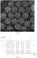
- the carrier particles of the present invention are mainly prepared by two structural units, the sphere and the sub-sphere, which are assembled microspheres of a raspberry-like structure and finally formed through chemical covalent reactions between the functional groups on the surface of the sphere and the sub-sphere, as shown in Figure 1 , and the preparation of the sphere and the sub-sphere structural units are respectively described as follows (in the following examples, quantum dots having two central emission wavelengths are used, however, following the method and encoding conception described as below, two or more kinds of quantum dots with an absolute value of the difference of the central emission wavelength of the quantum dots not lower than 30nm, or one type of quantum dots loaded in the internal or on the surface of the spheres and one kind of organic fluorescent dyes with a difference between their fluorescence central emission wavelength and that of the quantum dots loaded on the sphere not less than 50nm loaded in the internal of the sub-sphere can be used):
- the sphere can be a polymeric microsphere with a particle diameter of 0.5 ⁇ 20 ⁇ m, preferably 5 ⁇ 6 ⁇ m, and the microsphere has active functional groups on the surface, and the most preferred functional group is carboxyl.
- the most preferred polymeric microspheres are those loaded with magnetic nanoparticles in their internal.
- the polymeric mesoporous sphere can be a polystyrene-divinylbenzene (PS-DVB) copolymerized mesoporous microsphere having a pore size of 10nm ⁇ 70nm, and the particle size of the microsphere is 5 ⁇ 6 ⁇ m.
- PS-DVB polystyrene-divinylbenzene
- step one adjusting the concentration of the quantum dot in chloroform added, then QDs@PS@silica@MPS@PS-PAA encoded spheres having a variety of fluorescence intensity can be respectively obtained.
- step three and four it is not limited to prepare QDs@PS@silica@MPS@PS-PAA encoded microspheres by firstly performing surface-grafted modification using MPS and then acrylic acid polymerization.
- the surface of QDs@PS@silica microspheres obtained in step two can also be graft-modified with aminopropyltrimethoxysilane (APTMS) or aminopropyltriethoxysilane (APTES) to give QDs@PS@silica@APS, of which the surface is then chemical grafted with polyacrylic acid polymer, and the QDs@PS@silica@APTMS@PS-PAA encoded spheres with a variety of fluorescence intensity is obtained.
- ATMS aminopropyltrimethoxysilane
- APTES aminopropyltriethoxysilane
- Polymeric mesoporous microspheres loaded with fluorescence quantum dots having a central emission wavelength of 600 nm in their interior can be polystyrene-divinylbenzene (PS-DVB) copolymerized mesoporous microspheres having a pore size of 10 nm ⁇ 70 nm, and the particle size of microspheres can be 5 ⁇ 6 ⁇ m.
- PS-DVB polystyrene-divinylbenzene
- the basic method for preparing such encoded microspheres spheres is consistent with the method for preparing microspheres of type two, except that the quantum dots added in the interior of the mesoporous polymeric microspheres are red quantum dots whose central position of the emission spectrum is 600 nm, such as CdSe@ZnS nanocrystals with a central emission wavelength of 600 nm and a particle size of 4.7 ⁇ 5.2 nm.
- a number of encoded microspheres having completely independent fluorescence intensity can be obtained by adjusting the concentration of the quantum dot dispersion in chloroform added in step one.
- the polymeric sphere can be polystyrene-divinylbenzene (PS-DVB) copolymerized mesoporous microspheres having a pore size of 10 ⁇ 70nm, and the particle size of microspheres can be 5 ⁇ 6 ⁇ m.
- PS-DVB polystyrene-divinylbenzene
- the amount of the two kinds of quantum dots (such as CdSe@ZnS nanocrystals with a particle size of about 2.5nm and 5.0nm respectively) loaded in the interior of the polymeric mesoporous microspheres can be adjusted by regulating the concentration of quantum dots loaded, and a number of completely independent fluorescence intensity levels can be formed in the two kinds of fluorescence emission spectrum when detected in the flow cytometer.
- quantum dots such as CdSe@ZnS nanocrystals with a particle size of about 2.5nm and 5.0nm respectively
- the preparation method can refer to the method for preparing a sub-sphere in type two.
- the above polymeric microspheres material for preparing the sphere may also be one selected from the group consisting of polystyrene, copolymer of polystyrene and polyacrylic acid, and copolymer of polystyrene and polymethacrylic acid, and the functional group may also be one selected from the group consisting of hydrosulphonyl and hydroxyl.
- Non-fluorescent silica or polymer microspheres modified by amino or carboxyl on the surface.
- the microspheres have a particle size of 30 ⁇ 500 nm, and most preferably 200 nm.
- Silica microspheres loaded with fluorescence quantum dots having a central emission wavelength of 520nm on the surface The optimal particle size of silica microspheres is 200 nm, and the surface of the silica microspheres are modified with functional groups, preferably amino or carboxyl, and the quantum dots assembled on the surface of the silica microspheres can be CdSe@ZnS nanocrystals with a particle size of 2.4-2.6 nm.
- the basic preparation method for the sub-spheres of type two is as follows:
- a dispersion of 11 mg of silica particles (the particle size is 200 nm) in ethanol is centrifuged to remove the supernatant.
- 200 ⁇ L of ultrapure water is added and the obtained is ultrasonic dispersed and centrifuged to remove the supernatant, and the silica particles are redispersed in 3.6 mL of polycationic electrolytes (PDADMAC) solution (2mg/mL), mixed and adsorbed for 20 minutes, and centrifuged to remove the supernatant.
- PDADMAC polycationic electrolytes
- the solid particles obtained by centrifugation are redispersed in 1 mL of ultrapure water and washed with water for three times to obtain Silica@PDADMAC solid particles, which are dispersed in 4 mL of ultrapure water.
- the deposition process of two layers is completely identical to that of PDADMAC, and Silica@PDADMAC@PSS@PDADMAC(Silica@PE3)solid particles were finally obtained.
- the solid particles are dispersed in 2 mL of ultrapure water for use.
- the mixed solution is centrifuged to remove the supernatant, the solid particles obtained by centrifugation are redispersed in 1 mL of ultrapure water and washed with water for three times.
- the solid particles obtained by centrifugation are Silica@PE3@QDs fluorescent particles with a central emission wavelength of 520nm.
- the fluorescent silica particles are dispersed in 1 mL of ultrapure water for use.
- ⁇ -aminopropyltrimethoxysilane (APTMS) is added, and adsorbed for 30 minutes, and then 15 ⁇ L of ammonia is added, and the reaction is continued for 24 hours. After completion of the reaction, the obtained is centrifuged to remove the supernatant, and the solid particles obtained by centrifugation were redispersed in 1 mL of ultrapure water and washed with water for three times.
- the solid particles obtained by centrifugation are silica@PE3@QDs@Silica fluorescent sub-sphere modified by amino on the surface having a central emission wavelength of 520 nm.
- the above described fluorescent sub-spheres can be silica microspheres, but not limited to silica microspheres.
- Polymer microspheres modified by carboxyl or amino on the surface can also be template microspheres for assembling quantum dots.
- the fluorescent intensity of the above described fluorescent sub-spheres can be achieved by multilayered assembling quantum dots on the surface of the silica particles, that is, on the surface of the prepared Silica@PE3@QDs fluorescent sub-spheres (not coated with silicon), polycationic electrolyte PDADMAC is used to electrostatic assembling, and then another layer of QDs is assembled by the same method as above. Finally, a fluorescent sub-sphere assembled with two layers of QDs particles, namely Silica@PE3@QDs@QDs, is obtained. Similarly, the controllable assembling of multilayers of QDs can be achieved.
- Silica microspheres loaded with fluorescence quantum dots having a central emission wavelength of 600nm on the surface The optimal particle size of silica microspheres is 200 nm, and the surface of the silica microspheres are modified with functional groups, preferably amino or carboxyl, and the quantum dots assembled on the surface of the silica microspheres can be CdSe@ZnS nanocrystals with a particle size of 4.7-5.2 nm or other quantum dots crystal emitting fluorescence at the same wavelength.
- sub-spheres of type three The specific preparation method for sub-spheres of type three is consistent with that of sub-spheres of type two, except that the carboxyl quantum dots assembled on the surface are nanocrystals having a central emission wavelength of 600nm, and then the central emission wavelength of the finally obtained fluorescent sub-sphere is 600nm.
- the fluorescent sub-spheres of type three can be silica microspheres, but not limited to silica microspheres.
- Polymer microspheres modified by carboxyl or amino on the surface can also be template microspheres for assembling quantum dots.
- the fluorescent intensity of above described fluorescent sub-spheres can be achieved by multilayered assembling quantum dots on the surface of the silica particles, that is, on the surface of the prepared Silica@PE3@QDs fluorescent sub-spheres (not coated with silicon), polycationic electrolyte PDADMAC is used to electrostatically assembling, and then another layer of QDs is assembled by the same method as above. Finally, a fluorescent sub-sphere assembled with two layers of QDs particles, namely Silica@PE3@QDs@QDs, is obtained. Similarly, the controllable assembling of multi-layer QDs can be achieved.
- Silica microspheres of which the sub-sphere is assembled with two kinds of fluorescent quantum dots having a central emission wavelength of 520nm and 600nm respectively on the surface The optimal particle size of silica microspheres is 200 nm, and the surface of the silica microspheres are modified with functional groups, preferably amino or carboxyl, and the quantum dots assembled on the surface of the silica microspheres can be fluorescence quantum dots having a central emission wavelength of 520nm and 600nm, and the co-assembling of the two kinds of quantum dots is realized by layer-by-layer assembling.
- the method of layer-by-layer assembling is the same as that of assembling the second layer of quantum dots on the surface of silica sub-sphere of type two and type three.
- the controllable assembling of multi-layer quantum dots on the surface of the silica sub-sphere can be achieved.
- Silica microspheres covalently doped with fluorescein isothiocyanate (FITC) in the interior and modified with amino on the surface.
- the particle diameter of the silica microspheres is preferably 200 nm.
- the specific preparation method for the fluorescent sub-sphere is as follows:
- the fluorescent sub-spheres having a variety of independent fluorescence intensity are obtained.
- Fluorescent sub-spheres loaded with quantum dots in the interior are prepared by referring to Reference [ J.Mater.Chem., 2011,21,12520 ].
- the specific preparation method is as follows:
- the fluorescence intensity of the above described fluorescent sub-spheres can be adjusted by changing the volume of QDs/chloroform dispersion added.
- the above preparation method for the sub-spheres of type six is not limited to the method described in [ J.Mater.Chem., 2011,21,12520 ], it can be prepared by template method [ Langmuir2006, 22, 5604-5610 ] etc., or in situ polymerization method.
- the sub-spheres used can be polymers, or silica sub-spheres.
- the above polymeric nanospheres material for preparing sub-spheres can also be one selected from the group consisting of polystyrene, copolymer of polystyrene and polyacrylic acid, and copolymer of polystyrene and polymethacrylic acid.
- the functional group can also be one selected from the group consisting of hydrosulphonyl and hydroxyl.
- the surface of the sphere is covalently assembled with one layer of sub-spheres.
- the sphere may be any one type of the above sphere structural units, and the sub-sphere may also be any one type of the above sub-sphere structural units.
- a specific covalent assembling method is as follows:
- the surface of the sphere is covalently assembled with two types of sub-spheres.
- the sphere may be any one type of the above sphere structural units, and the sub-sphere may also be any two types of the s above sub-sphere structural units.
- the specific covalently assembling method is the same as that described in method one, except that the ratio of the two types of sub-spheres can be adjusted according to the encoding requirements of emission spectrum (the central emission wavelength) and fluorescence intensity.
- a sphere encoded fluorescent microsphere Preparation of a sphere encoded fluorescent microsphere.
- the spheres of type four modified by amino on the surface namely polymeric mesoporous microspheres loaded with two kinds of quantum dots having a central emission wavelength of 520nm and 600nm respectively in the interior, were selected.
- the sub-spheres of type one namely non-fluorescent silica or polymer microspheres modified by carboxyl on the surface were selected.
- the sphere and the sub-sphere were covalently assembled by assembling method one to obtain a encoded fluorescent assembled microsphere having carboxyl on the surface.
- microspheres co-encoded by green fluorescent spheres and orange fluorescent sub-spheres Preparation of microspheres co-encoded by green fluorescent spheres and orange fluorescent sub-spheres.
- the spheres of type two modified by amino on the surface were selected, and the sub-spheres of type three modified by carboxyl on the surface were selected.
- the spheres and the sub-spheres were covalently assembled by assembling method one to obtain a co-encoded fluorescent assembled microsphere having carboxyl on the surface.
- FIG. 2 it is distribution diagram of 15 kinds of fluorescent encoding microspheres in the two-color fluorescent channel, wherein the horizontal axis and the vertical axis, respectively, means the fluorescence signal at 520 nm and 600 nm, the fluorescence intensity increases along with the arrow direction.
- the numbers 1 ⁇ 5 on the horizontal axis and the numbers 1 ⁇ 3 on the vertical axis represent 5 kinds of independent fluorescence intensities of the quantum dots of 520 nm and 600 nm respectively which were achieved by the gradient setting of the loading amounts, thereby forming spheres of 5 kinds of fluorescence intensity and sub-spheres of 3 kinds of fluorescence intensity, and then 15 kinds of fluorescent encoding microspheres were formed by cross-combination.
- the fluorescent signal distribution intervals of each kind of fluorescent encoding microspheres were shown in a total of 15 closed curves in Figure 2 .
- microspheres co-encoded by orange fluorescent spheres and green fluorescent sub-spheres Preparation of microspheres co-encoded by orange fluorescent spheres and green fluorescent sub-spheres.
- the spheres of type three modified by carboxyl on the surface were selected, and the of sub-spheres of type two or six modified by amino on the surface were selected.
- the sphere and the sub-sphere were covalently assembled by assembling method one to obtain co-encoded fluorescent assembled microsphere having amino on the surface.
- microspheres co-encoded by non-fluorescent spheres and green fluorescence sub-spheres Preparation of microspheres co-encoded by non-fluorescent spheres and green fluorescence sub-spheres.
- the spheres of type one modified by amino on the surface were selected, and the fluorescent sub-spheres of type two and one modified by carboxyl on the surface were selected.
- the spheres and the sub-spheres were covalently assembled by assembling method two to obtain co-encoded fluorescent assembled microsphere having carboxyl on the surface.
- microspheres co-encoded by non-fluorescent spheres and orange fluorescence sub-spheres Preparation of microspheres co-encoded by non-fluorescent spheres and orange fluorescence sub-spheres.
- the spheres of type one modified by amino on the surface were selected, and the fluorescent sub-spheres of type three and one modified by carboxyl on the surface were selected.
- the spheres and the sub-spheres were covalently assembled by assembling method two to obtain co-encoded fluorescent assembled microsphere having carboxyl on the surface.
- microspheres co-encoded by non-fluorescent spheres and green fluorescence sub-spheres Preparation of microspheres co-encoded by non-fluorescent spheres and green fluorescence sub-spheres.
- the spheres of type three modified by amino on the surface were selected, and the fluorescent sub-spheres of type five and one modified by carboxyl on the surface were selected.
- the spheres and the sub-spheres were covalently assembled by assembling method two to obtain co-encoded fluorescent assembled microsphere having carboxyl on the surface.
- microspheres co-encoded by non-fluorescent spheres and green/orange dual fluorescent sub-spheres Preparation of microspheres co-encoded by non-fluorescent spheres and green/orange dual fluorescent sub-spheres.
- the spheres of type one modified by amino on the surface were selected, and the sub-spheres of type four modified by carboxyl on the surface were selected.
- the spheres and the sub-spheres were covalently assembled by assembling method one to obtain co-encoded fluorescent assembled microsphere having carboxyl on the surface.
- the co-assembling encoding method for the sphere and the sub-sphere of the present invention is not limited to those listed in above examples, and can be combined freely according to the encoding requirements.
- Microspheres co-encoded by three-color fluorescent spheres and sub-spheres are co-encoded by three-color fluorescent spheres and sub-spheres.
- quantum dots having a third fluorescence emission spectrum such as CdSe@ZnS having a central emission wavelength of 670nm
- CdSe@ZnS having a central emission wavelength of 670nm could also be loaded in the interior of the non-fluorescent spheres., and by adjusting the content of loaded quantum dots, the preparation of the spheres of type two having 2 ⁇ 10 kinds of independent fluorescence intensity can be firstly achieved.
- the assembled microspheres could be further encoded using more than two kinds of quantum dots having different central emission wavelengths by the above-described method.
Landscapes
- Chemical & Material Sciences (AREA)
- Engineering & Computer Science (AREA)
- Nanotechnology (AREA)
- Materials Engineering (AREA)
- Organic Chemistry (AREA)
- Crystallography & Structural Chemistry (AREA)
- Physics & Mathematics (AREA)
- Inorganic Chemistry (AREA)
- General Physics & Mathematics (AREA)
- Condensed Matter Physics & Semiconductors (AREA)
- Composite Materials (AREA)
- Manufacturing & Machinery (AREA)
- Life Sciences & Earth Sciences (AREA)
- Biophysics (AREA)
- Optics & Photonics (AREA)
- Investigating, Analyzing Materials By Fluorescence Or Luminescence (AREA)
- Luminescent Compositions (AREA)
- Led Device Packages (AREA)
Applications Claiming Priority (2)
| Application Number | Priority Date | Filing Date | Title |
|---|---|---|---|
| CN201410247053.3A CN105219373B (zh) | 2014-06-05 | 2014-06-05 | 一种载体颗粒及其制备方法 |
| PCT/CN2015/086144 WO2015185023A2 (zh) | 2014-06-05 | 2015-08-05 | 一种载体颗粒及其制备方法 |
Publications (4)
| Publication Number | Publication Date |
|---|---|
| EP3159391A2 true EP3159391A2 (de) | 2017-04-26 |
| EP3159391A4 EP3159391A4 (de) | 2019-11-13 |
| EP3159391B1 EP3159391B1 (de) | 2024-07-03 |
| EP3159391C0 EP3159391C0 (de) | 2024-07-03 |
Family
ID=54767516
Family Applications (1)
| Application Number | Title | Priority Date | Filing Date |
|---|---|---|---|
| EP15802518.9A Active EP3159391B1 (de) | 2014-06-05 | 2015-08-05 | Trägerpartikel und herstellungsverfahren dafür |
Country Status (6)
| Country | Link |
|---|---|
| US (1) | US10421903B2 (de) |
| EP (1) | EP3159391B1 (de) |
| JP (1) | JP6487540B2 (de) |
| KR (1) | KR101974571B1 (de) |
| CN (1) | CN105219373B (de) |
| WO (1) | WO2015185023A2 (de) |
Families Citing this family (17)
| Publication number | Priority date | Publication date | Assignee | Title |
|---|---|---|---|---|
| CN106398683B (zh) * | 2016-08-29 | 2018-09-11 | 上海交通大学 | 一种制备三色编码微球组合物的方法 |
| CN108221059B (zh) * | 2016-12-13 | 2023-02-21 | 中翰盛泰生物技术股份有限公司 | 一种光学编码库及其载体的制备方法和应用 |
| JP2018172531A (ja) * | 2017-03-31 | 2018-11-08 | 株式会社Dnpファインケミカル | 複合粒子および複合粒子製造方法 |
| CN107478622B (zh) * | 2017-06-29 | 2020-06-02 | 深圳市液芯科技有限公司 | 一种荧光编码微球的解码方法和系统 |
| KR101960616B1 (ko) * | 2017-09-28 | 2019-03-21 | (주)바이오스퀘어 | 다중 양자점 기반 고감도 생체분자 검출법 |
| TWI650398B (zh) * | 2017-12-08 | 2019-02-11 | Chi Mei Corporation | 發光材料與應用之顯示裝置 |
| CN110484234B (zh) * | 2018-05-14 | 2023-12-05 | 深圳唯公生物科技有限公司 | 一种荧光微球及其制备和荧光编码的方法 |
| CN110967336A (zh) * | 2018-09-28 | 2020-04-07 | 陈洁 | 牙周疾病检测试剂盒及使用方法 |
| CN112175604B (zh) * | 2019-07-04 | 2024-05-07 | 致晶科技(北京)有限公司 | 一种多层包覆结构的复合粉体以及制备方法、应用 |
| CN111117606B (zh) * | 2019-12-31 | 2022-05-20 | 北京市计量检测科学研究院 | 一种碳量子点荧光微球标准物质及其制备方法 |
| CN112973650B (zh) * | 2021-02-08 | 2022-02-08 | 厦门大学 | 一种纳微复合球及其制备方法和应用 |
| US20250033014A1 (en) * | 2021-12-10 | 2025-01-30 | Zeon Corporation | Hollow particles, method for producing hollow particles, and resin composition |
| CN114577761A (zh) * | 2022-01-28 | 2022-06-03 | 北京胡曼智造科技有限责任公司 | 核壳型磁性荧光微球及其制备方法和应用 |
| CN114517090B (zh) * | 2022-02-25 | 2023-08-22 | 中国药科大学 | 一种高亮度的近红外荧光复合微球及其制备方法 |
| CN115181562B (zh) * | 2022-06-17 | 2025-06-06 | 深圳传世生物医疗有限公司 | 一种量子点荧光微球及其制备方法与应用 |
| CN116284978B (zh) * | 2022-12-16 | 2024-09-20 | 厦门为正生物科技股份有限公司 | 一种荧光微球及其制备方法与应用 |
| CN117903786A (zh) * | 2023-12-25 | 2024-04-19 | 中翰盛泰生物技术股份有限公司 | 一种量子点磁性荧光编码微球及其制备方法 |
Family Cites Families (18)
| Publication number | Priority date | Publication date | Assignee | Title |
|---|---|---|---|---|
| ATE239801T1 (de) * | 1998-01-22 | 2003-05-15 | Luminex Corp | Mikropartikel mit multiplen fluoreszenz-signalen |
| GB2445579A (en) * | 2007-01-11 | 2008-07-16 | Secr Defence | An encoded microsphere |
| GB2445580A (en) * | 2007-01-11 | 2008-07-16 | Secr Defence | An encoded microsphere |
| US20080230750A1 (en) * | 2007-03-20 | 2008-09-25 | Evident Technologies, Inc. | Powdered quantum dots |
| CN100565185C (zh) * | 2008-01-08 | 2009-12-02 | 东南大学 | 一种光子晶体复合编码微球及制备方法 |
| US20110014296A1 (en) * | 2009-07-17 | 2011-01-20 | National Chiao Tung University | Drug Delivery Nanodevice, its Preparation Method and Uses Thereof |
| KR101195771B1 (ko) * | 2010-06-04 | 2012-11-05 | 한국과학기술연구원 | 초상자성 클러스터-나노입자-기공체 복합 비드 및 그 제조방법 |
| US8507094B2 (en) * | 2010-06-04 | 2013-08-13 | Korea Institute Of Science And Technology | Superparamagnetic cluster-nano particles-porous composite bead and fabrication method thereof |
| JP5578613B2 (ja) | 2010-08-04 | 2014-08-27 | 国立大学法人名古屋大学 | 磁性ナノ粒子複合体及び当該磁性ナノ粒子複合体による細胞の標識方法 |
| CN101953975B (zh) | 2010-09-30 | 2012-02-01 | 倪海清 | 肿瘤内服中草药片剂及制备方法 |
| JPWO2012153820A1 (ja) * | 2011-05-12 | 2014-07-31 | コニカミノルタ株式会社 | X線吸収蛍光ナノ粒子 |
| WO2013001685A1 (ja) * | 2011-06-29 | 2013-01-03 | パナソニック株式会社 | 複合蛍光体および発光装置 |
| CN102416180B (zh) * | 2011-12-14 | 2013-04-17 | 浙江理工大学 | 一种功能集成药物载体及其制备方法 |
| CN102863963B (zh) * | 2012-05-31 | 2014-04-16 | 浙江理工大学 | 一种SiO2-QDs的纳米复合材料的制备方法及应用 |
| CN103134926B (zh) | 2013-02-27 | 2015-05-27 | 上海交通大学 | 一种磁性微球载体及其制备方法 |
| CN103571493B (zh) * | 2013-08-20 | 2016-02-24 | 苏州科技学院 | 聚苯胺磁性微球连接荧光量子点制备磁性荧光双功能微球 |
| CN103571494B (zh) * | 2013-08-20 | 2016-02-24 | 苏州科技学院 | 甘露寡糖磁性微球连接荧光量子点制备磁性荧光双功能微球 |
| CN103881701A (zh) * | 2013-12-30 | 2014-06-25 | 安徽师范大学 | 一种磷光能量转移体系,其合成方法,用途以及凝血酶的检测方法 |
-
2014
- 2014-06-05 CN CN201410247053.3A patent/CN105219373B/zh active Active
-
2015
- 2015-08-05 EP EP15802518.9A patent/EP3159391B1/de active Active
- 2015-08-05 US US15/316,131 patent/US10421903B2/en active Active
- 2015-08-05 WO PCT/CN2015/086144 patent/WO2015185023A2/zh not_active Ceased
- 2015-08-05 JP JP2017516024A patent/JP6487540B2/ja active Active
- 2015-08-05 KR KR1020177000296A patent/KR101974571B1/ko active Active
Also Published As
| Publication number | Publication date |
|---|---|
| KR101974571B1 (ko) | 2019-05-02 |
| JP2017525832A (ja) | 2017-09-07 |
| EP3159391B1 (de) | 2024-07-03 |
| WO2015185023A3 (zh) | 2016-01-28 |
| EP3159391A4 (de) | 2019-11-13 |
| CN105219373A (zh) | 2016-01-06 |
| EP3159391C0 (de) | 2024-07-03 |
| WO2015185023A2 (zh) | 2015-12-10 |
| KR20170117360A (ko) | 2017-10-23 |
| JP6487540B2 (ja) | 2019-03-20 |
| CN105219373B (zh) | 2019-06-25 |
| US10421903B2 (en) | 2019-09-24 |
| US20170121603A1 (en) | 2017-05-04 |
Similar Documents
| Publication | Publication Date | Title |
|---|---|---|
| EP3159391B1 (de) | Trägerpartikel und herstellungsverfahren dafür | |
| Bele et al. | Preparation and flow cytometry of uniform silica-fluorescent dye microspheres | |
| US7648845B2 (en) | Porous materials embedded with nanospecies, methods of fabrication thereof, and methods of use thereof | |
| CN109233836B (zh) | 量子点荧光微球及其制备方法 | |
| WO2022063337A1 (zh) | 荧光编码微球和阵列及制备方法 | |
| JP2008533214A (ja) | ナノ粒子捕捉球状複合体、それらの製造プロセスおよび使用 | |
| CN101321686A (zh) | 用于多路信号传递和光编码的多组分纳米颗粒 | |
| US20070275383A1 (en) | Novel Hybrid Probes with Heightened Luminescence | |
| WO2022063336A1 (zh) | 编码微球和阵列及制备方法 | |
| Masoomi et al. | A facile polymer mediated dye incorporation method for fluorescence encoded microbeads with large encoding capacities | |
| EP3666850B1 (de) | Quantenpunkt-dotierte nanopartikel, verfahren zur herstellung davon und bioplattform enthaltend quantenpunkt-dotierte nanopartikel | |
| Masoomi et al. | Ultrabright dye-loaded spherical polyelectrolyte brushes and their fundamental structure-fluorescence tuning principles | |
| CN115181562B (zh) | 一种量子点荧光微球及其制备方法与应用 | |
| Ma et al. | Synthesis and application of quantum dot-tagged fluorescent microbeads | |
| CN114507524B (zh) | 一种量子点荧光编码聚乳酸微球及其制备方法和应用 | |
| HK1261395A1 (en) | Carrier particle and preparation method therefor | |
| HK1261395B (en) | Carrier particle and preparation method therefor | |
| RU2532559C1 (ru) | Способ формирования многофункциональных микросистем | |
| RU2583022C2 (ru) | Способ получения нанокомпозитов на основе наночастиц золота, покрытых оболочкой из оксида кремния, и квантовых точек | |
| CN108221059B (zh) | 一种光学编码库及其载体的制备方法和应用 | |
| Yang et al. | A versatile strategy for loading silica particles with dyes and quantum dots | |
| Ning et al. | Versatile fabrication of water-dispersible nanoparticle–amphiphilic copolymer composite microspheres with specific functionalities | |
| Yang et al. | Quantum dot-encoded fluorescent beads for biodetection and imaging | |
| Ren et al. | Synthesis and Spectroscopic Properties of Silica− Dye− Semiconductor Nanocrystal Hybrid Particles | |
| Guo et al. | Quantum dot-encoded beads for ultrasensitive detection |
Legal Events
| Date | Code | Title | Description |
|---|---|---|---|
| STAA | Information on the status of an ep patent application or granted ep patent |
Free format text: STATUS: THE INTERNATIONAL PUBLICATION HAS BEEN MADE |
|
| PUAI | Public reference made under article 153(3) epc to a published international application that has entered the european phase |
Free format text: ORIGINAL CODE: 0009012 |
|
| STAA | Information on the status of an ep patent application or granted ep patent |
Free format text: STATUS: REQUEST FOR EXAMINATION WAS MADE |
|
| 17P | Request for examination filed |
Effective date: 20161206 |
|
| AK | Designated contracting states |
Kind code of ref document: A2 Designated state(s): AL AT BE BG CH CY CZ DE DK EE ES FI FR GB GR HR HU IE IS IT LI LT LU LV MC MK MT NL NO PL PT RO RS SE SI SK SM TR |
|
| AX | Request for extension of the european patent |
Extension state: BA ME |
|
| XX | Miscellaneous (additional remarks) |
Free format text: A REQUEST FOR RESTORATION OF THE RIGHT OF PRIORITY UNDER RULE 49TER.2 PCT IS PENDING BEFORE THE EPO AS DESIGNATED OFFICE. |
|
| DAV | Request for validation of the european patent (deleted) | ||
| DAX | Request for extension of the european patent (deleted) | ||
| APBK | Appeal reference recorded |
Free format text: ORIGINAL CODE: EPIDOSNREFNE |
|
| APBN | Date of receipt of notice of appeal recorded |
Free format text: ORIGINAL CODE: EPIDOSNNOA2E |
|
| APBR | Date of receipt of statement of grounds of appeal recorded |
Free format text: ORIGINAL CODE: EPIDOSNNOA3E |
|
| APAF | Appeal reference modified |
Free format text: ORIGINAL CODE: EPIDOSCREFNE |
|
| APBT | Appeal procedure closed |
Free format text: ORIGINAL CODE: EPIDOSNNOA9E |
|
| A4 | Supplementary search report drawn up and despatched |
Effective date: 20191011 |
|
| RIC1 | Information provided on ipc code assigned before grant |
Ipc: B82Y 30/00 20110101ALI20191007BHEP Ipc: B82Y 25/00 20110101ALI20191007BHEP Ipc: C09K 11/02 20060101AFI20191007BHEP Ipc: B82Y 40/00 20110101ALI20191007BHEP Ipc: C09K 11/06 20060101ALI20191007BHEP Ipc: C09K 11/88 20060101ALI20191007BHEP Ipc: B82Y 20/00 20110101ALI20191007BHEP |
|
| REG | Reference to a national code |
Ref country code: HK Ref legal event code: DE Ref document number: 1261395 Country of ref document: HK |
|
| STAA | Information on the status of an ep patent application or granted ep patent |
Free format text: STATUS: EXAMINATION IS IN PROGRESS |
|
| 17Q | First examination report despatched |
Effective date: 20210526 |
|
| GRAP | Despatch of communication of intention to grant a patent |
Free format text: ORIGINAL CODE: EPIDOSNIGR1 |
|
| STAA | Information on the status of an ep patent application or granted ep patent |
Free format text: STATUS: GRANT OF PATENT IS INTENDED |
|
| INTG | Intention to grant announced |
Effective date: 20240122 |
|
| GRAS | Grant fee paid |
Free format text: ORIGINAL CODE: EPIDOSNIGR3 |
|
| GRAA | (expected) grant |
Free format text: ORIGINAL CODE: 0009210 |
|
| STAA | Information on the status of an ep patent application or granted ep patent |
Free format text: STATUS: THE PATENT HAS BEEN GRANTED |
|
| AK | Designated contracting states |
Kind code of ref document: B1 Designated state(s): AL AT BE BG CH CY CZ DE DK EE ES FI FR GB GR HR HU IE IS IT LI LT LU LV MC MK MT NL NO PL PT RO RS SE SI SK SM TR |
|
| XX | Miscellaneous (additional remarks) |
Free format text: A REQUEST FOR RESTORATION OF THE RIGHT OF PRIORITY UNDER RULE 49TER.2 PCT IS PENDING BEFORE THE EPO AS DESIGNATED OFFICE |
|
| REG | Reference to a national code |
Ref country code: CH Ref legal event code: EP |
|
| REG | Reference to a national code |
Ref country code: DE Ref legal event code: R096 Ref document number: 602015089122 Country of ref document: DE |
|
| U01 | Request for unitary effect filed |
Effective date: 20240802 |
|
| U07 | Unitary effect registered |
Designated state(s): AT BE BG DE DK EE FI FR IT LT LU LV MT NL PT SE SI Effective date: 20240823 |
|
| U20 | Renewal fee for the european patent with unitary effect paid |
Year of fee payment: 10 Effective date: 20240925 |
|
| PG25 | Lapsed in a contracting state [announced via postgrant information from national office to epo] |
Ref country code: NO Free format text: LAPSE BECAUSE OF FAILURE TO SUBMIT A TRANSLATION OF THE DESCRIPTION OR TO PAY THE FEE WITHIN THE PRESCRIBED TIME-LIMIT Effective date: 20241003 |
|
| PG25 | Lapsed in a contracting state [announced via postgrant information from national office to epo] |
Ref country code: GR Free format text: LAPSE BECAUSE OF FAILURE TO SUBMIT A TRANSLATION OF THE DESCRIPTION OR TO PAY THE FEE WITHIN THE PRESCRIBED TIME-LIMIT Effective date: 20241004 Ref country code: PL Free format text: LAPSE BECAUSE OF FAILURE TO SUBMIT A TRANSLATION OF THE DESCRIPTION OR TO PAY THE FEE WITHIN THE PRESCRIBED TIME-LIMIT Effective date: 20240703 |
|
| PG25 | Lapsed in a contracting state [announced via postgrant information from national office to epo] |
Ref country code: IS Free format text: LAPSE BECAUSE OF FAILURE TO SUBMIT A TRANSLATION OF THE DESCRIPTION OR TO PAY THE FEE WITHIN THE PRESCRIBED TIME-LIMIT Effective date: 20241103 |
|
| PG25 | Lapsed in a contracting state [announced via postgrant information from national office to epo] |
Ref country code: CZ Free format text: LAPSE BECAUSE OF FAILURE TO SUBMIT A TRANSLATION OF THE DESCRIPTION OR TO PAY THE FEE WITHIN THE PRESCRIBED TIME-LIMIT Effective date: 20240703 Ref country code: HR Free format text: LAPSE BECAUSE OF FAILURE TO SUBMIT A TRANSLATION OF THE DESCRIPTION OR TO PAY THE FEE WITHIN THE PRESCRIBED TIME-LIMIT Effective date: 20240703 |
|
| PG25 | Lapsed in a contracting state [announced via postgrant information from national office to epo] |
Ref country code: ES Free format text: LAPSE BECAUSE OF FAILURE TO SUBMIT A TRANSLATION OF THE DESCRIPTION OR TO PAY THE FEE WITHIN THE PRESCRIBED TIME-LIMIT Effective date: 20240703 Ref country code: RS Free format text: LAPSE BECAUSE OF FAILURE TO SUBMIT A TRANSLATION OF THE DESCRIPTION OR TO PAY THE FEE WITHIN THE PRESCRIBED TIME-LIMIT Effective date: 20241003 |
|
| PG25 | Lapsed in a contracting state [announced via postgrant information from national office to epo] |
Ref country code: RS Free format text: LAPSE BECAUSE OF FAILURE TO SUBMIT A TRANSLATION OF THE DESCRIPTION OR TO PAY THE FEE WITHIN THE PRESCRIBED TIME-LIMIT Effective date: 20241003 Ref country code: PL Free format text: LAPSE BECAUSE OF FAILURE TO SUBMIT A TRANSLATION OF THE DESCRIPTION OR TO PAY THE FEE WITHIN THE PRESCRIBED TIME-LIMIT Effective date: 20240703 Ref country code: NO Free format text: LAPSE BECAUSE OF FAILURE TO SUBMIT A TRANSLATION OF THE DESCRIPTION OR TO PAY THE FEE WITHIN THE PRESCRIBED TIME-LIMIT Effective date: 20241003 Ref country code: IS Free format text: LAPSE BECAUSE OF FAILURE TO SUBMIT A TRANSLATION OF THE DESCRIPTION OR TO PAY THE FEE WITHIN THE PRESCRIBED TIME-LIMIT Effective date: 20241103 Ref country code: HR Free format text: LAPSE BECAUSE OF FAILURE TO SUBMIT A TRANSLATION OF THE DESCRIPTION OR TO PAY THE FEE WITHIN THE PRESCRIBED TIME-LIMIT Effective date: 20240703 Ref country code: GR Free format text: LAPSE BECAUSE OF FAILURE TO SUBMIT A TRANSLATION OF THE DESCRIPTION OR TO PAY THE FEE WITHIN THE PRESCRIBED TIME-LIMIT Effective date: 20241004 Ref country code: ES Free format text: LAPSE BECAUSE OF FAILURE TO SUBMIT A TRANSLATION OF THE DESCRIPTION OR TO PAY THE FEE WITHIN THE PRESCRIBED TIME-LIMIT Effective date: 20240703 Ref country code: CZ Free format text: LAPSE BECAUSE OF FAILURE TO SUBMIT A TRANSLATION OF THE DESCRIPTION OR TO PAY THE FEE WITHIN THE PRESCRIBED TIME-LIMIT Effective date: 20240703 |
|
| REG | Reference to a national code |
Ref country code: CH Ref legal event code: PL |
|
| PG25 | Lapsed in a contracting state [announced via postgrant information from national office to epo] |
Ref country code: SM Free format text: LAPSE BECAUSE OF FAILURE TO SUBMIT A TRANSLATION OF THE DESCRIPTION OR TO PAY THE FEE WITHIN THE PRESCRIBED TIME-LIMIT Effective date: 20240703 |
|
| PG25 | Lapsed in a contracting state [announced via postgrant information from national office to epo] |
Ref country code: MC Free format text: LAPSE BECAUSE OF FAILURE TO SUBMIT A TRANSLATION OF THE DESCRIPTION OR TO PAY THE FEE WITHIN THE PRESCRIBED TIME-LIMIT Effective date: 20240703 Ref country code: CH Free format text: LAPSE BECAUSE OF NON-PAYMENT OF DUE FEES Effective date: 20240831 |
|
| PG25 | Lapsed in a contracting state [announced via postgrant information from national office to epo] |
Ref country code: SK Free format text: LAPSE BECAUSE OF FAILURE TO SUBMIT A TRANSLATION OF THE DESCRIPTION OR TO PAY THE FEE WITHIN THE PRESCRIBED TIME-LIMIT Effective date: 20240703 |
|
| PLBE | No opposition filed within time limit |
Free format text: ORIGINAL CODE: 0009261 |
|
| STAA | Information on the status of an ep patent application or granted ep patent |
Free format text: STATUS: NO OPPOSITION FILED WITHIN TIME LIMIT |
|
| 26N | No opposition filed |
Effective date: 20250404 |
|
| PG25 | Lapsed in a contracting state [announced via postgrant information from national office to epo] |
Ref country code: IE Free format text: LAPSE BECAUSE OF NON-PAYMENT OF DUE FEES Effective date: 20240805 |
|
| U20 | Renewal fee for the european patent with unitary effect paid |
Year of fee payment: 11 Effective date: 20250827 |
|
| PGFP | Annual fee paid to national office [announced via postgrant information from national office to epo] |
Ref country code: GB Payment date: 20250820 Year of fee payment: 11 |
|
| PG25 | Lapsed in a contracting state [announced via postgrant information from national office to epo] |
Ref country code: RO Free format text: LAPSE BECAUSE OF FAILURE TO SUBMIT A TRANSLATION OF THE DESCRIPTION OR TO PAY THE FEE WITHIN THE PRESCRIBED TIME-LIMIT Effective date: 20240703 |
|
| PG25 | Lapsed in a contracting state [announced via postgrant information from national office to epo] |
Ref country code: CY Free format text: LAPSE BECAUSE OF FAILURE TO SUBMIT A TRANSLATION OF THE DESCRIPTION OR TO PAY THE FEE WITHIN THE PRESCRIBED TIME-LIMIT; INVALID AB INITIO Effective date: 20150805 |
|
| PG25 | Lapsed in a contracting state [announced via postgrant information from national office to epo] |
Ref country code: HU Free format text: LAPSE BECAUSE OF FAILURE TO SUBMIT A TRANSLATION OF THE DESCRIPTION OR TO PAY THE FEE WITHIN THE PRESCRIBED TIME-LIMIT; INVALID AB INITIO Effective date: 20150805 |