EP3159091B1 - Joint processing method and dome member - Google Patents
Joint processing method and dome member Download PDFInfo
- Publication number
- EP3159091B1 EP3159091B1 EP15845443.9A EP15845443A EP3159091B1 EP 3159091 B1 EP3159091 B1 EP 3159091B1 EP 15845443 A EP15845443 A EP 15845443A EP 3159091 B1 EP3159091 B1 EP 3159091B1
- Authority
- EP
- European Patent Office
- Prior art keywords
- joint
- cold working
- metal material
- plate
- heat treatment
- Prior art date
- Legal status (The legal status is an assumption and is not a legal conclusion. Google has not performed a legal analysis and makes no representation as to the accuracy of the status listed.)
- Active
Links
Images




Classifications
-
- B—PERFORMING OPERATIONS; TRANSPORTING
- B23—MACHINE TOOLS; METAL-WORKING NOT OTHERWISE PROVIDED FOR
- B23K—SOLDERING OR UNSOLDERING; WELDING; CLADDING OR PLATING BY SOLDERING OR WELDING; CUTTING BY APPLYING HEAT LOCALLY, e.g. FLAME CUTTING; WORKING BY LASER BEAM
- B23K20/00—Non-electric welding by applying impact or other pressure, with or without the application of heat, e.g. cladding or plating
- B23K20/12—Non-electric welding by applying impact or other pressure, with or without the application of heat, e.g. cladding or plating the heat being generated by friction; Friction welding
- B23K20/122—Non-electric welding by applying impact or other pressure, with or without the application of heat, e.g. cladding or plating the heat being generated by friction; Friction welding using a non-consumable tool, e.g. friction stir welding
- B23K20/1275—Non-electric welding by applying impact or other pressure, with or without the application of heat, e.g. cladding or plating the heat being generated by friction; Friction welding using a non-consumable tool, e.g. friction stir welding involving metallurgical change
-
- B—PERFORMING OPERATIONS; TRANSPORTING
- B23—MACHINE TOOLS; METAL-WORKING NOT OTHERWISE PROVIDED FOR
- B23K—SOLDERING OR UNSOLDERING; WELDING; CLADDING OR PLATING BY SOLDERING OR WELDING; CUTTING BY APPLYING HEAT LOCALLY, e.g. FLAME CUTTING; WORKING BY LASER BEAM
- B23K20/00—Non-electric welding by applying impact or other pressure, with or without the application of heat, e.g. cladding or plating
- B23K20/12—Non-electric welding by applying impact or other pressure, with or without the application of heat, e.g. cladding or plating the heat being generated by friction; Friction welding
- B23K20/122—Non-electric welding by applying impact or other pressure, with or without the application of heat, e.g. cladding or plating the heat being generated by friction; Friction welding using a non-consumable tool, e.g. friction stir welding
-
- B—PERFORMING OPERATIONS; TRANSPORTING
- B21—MECHANICAL METAL-WORKING WITHOUT ESSENTIALLY REMOVING MATERIAL; PUNCHING METAL
- B21D—WORKING OR PROCESSING OF SHEET METAL OR METAL TUBES, RODS OR PROFILES WITHOUT ESSENTIALLY REMOVING MATERIAL; PUNCHING METAL
- B21D22/00—Shaping without cutting, by stamping, spinning, or deep-drawing
- B21D22/14—Spinning
-
- B—PERFORMING OPERATIONS; TRANSPORTING
- B23—MACHINE TOOLS; METAL-WORKING NOT OTHERWISE PROVIDED FOR
- B23K—SOLDERING OR UNSOLDERING; WELDING; CLADDING OR PLATING BY SOLDERING OR WELDING; CUTTING BY APPLYING HEAT LOCALLY, e.g. FLAME CUTTING; WORKING BY LASER BEAM
- B23K20/00—Non-electric welding by applying impact or other pressure, with or without the application of heat, e.g. cladding or plating
- B23K20/22—Non-electric welding by applying impact or other pressure, with or without the application of heat, e.g. cladding or plating taking account of the properties of the materials to be welded
- B23K20/233—Non-electric welding by applying impact or other pressure, with or without the application of heat, e.g. cladding or plating taking account of the properties of the materials to be welded without ferrous layer
- B23K20/2336—Non-electric welding by applying impact or other pressure, with or without the application of heat, e.g. cladding or plating taking account of the properties of the materials to be welded without ferrous layer both layers being aluminium
-
- C—CHEMISTRY; METALLURGY
- C22—METALLURGY; FERROUS OR NON-FERROUS ALLOYS; TREATMENT OF ALLOYS OR NON-FERROUS METALS
- C22F—CHANGING THE PHYSICAL STRUCTURE OF NON-FERROUS METALS AND NON-FERROUS ALLOYS
- C22F1/00—Changing the physical structure of non-ferrous metals or alloys by heat treatment or by hot or cold working
- C22F1/04—Changing the physical structure of non-ferrous metals or alloys by heat treatment or by hot or cold working of aluminium or alloys based thereon
-
- F—MECHANICAL ENGINEERING; LIGHTING; HEATING; WEAPONS; BLASTING
- F16—ENGINEERING ELEMENTS AND UNITS; GENERAL MEASURES FOR PRODUCING AND MAINTAINING EFFECTIVE FUNCTIONING OF MACHINES OR INSTALLATIONS; THERMAL INSULATION IN GENERAL
- F16B—DEVICES FOR FASTENING OR SECURING CONSTRUCTIONAL ELEMENTS OR MACHINE PARTS TOGETHER, e.g. NAILS, BOLTS, CIRCLIPS, CLAMPS, CLIPS OR WEDGES; JOINTS OR JOINTING
- F16B5/00—Joining sheets or plates, e.g. panels, to one another or to strips or bars parallel to them
- F16B5/08—Joining sheets or plates, e.g. panels, to one another or to strips or bars parallel to them by means of welds or the like
-
- B—PERFORMING OPERATIONS; TRANSPORTING
- B23—MACHINE TOOLS; METAL-WORKING NOT OTHERWISE PROVIDED FOR
- B23K—SOLDERING OR UNSOLDERING; WELDING; CLADDING OR PLATING BY SOLDERING OR WELDING; CUTTING BY APPLYING HEAT LOCALLY, e.g. FLAME CUTTING; WORKING BY LASER BEAM
- B23K2103/00—Materials to be soldered, welded or cut
- B23K2103/08—Non-ferrous metals or alloys
- B23K2103/10—Aluminium or alloys thereof
Definitions
- the present invention relates to a joint processing method and a dome member that perform processing on a joint formed by friction stir welding.
- a method of welding two or more plates by friction stir welding to form a workpiece and rotating the workpiece to form a dome having a semispherical body shape is known (for example, refer to PTL 1).
- a material such as an aluminum scandium alloy, which delays growth of grains, is disposed between abutting edges between the plates.
- a method of suppressing abnormal growth of grains accompanying solution heat treatment in a friction stir joint of an aluminum alloy a method of performing intermediate anneal heat treatment after friction stir welding and performing solution heat treatment after the intermediate anneal heat treatment is known (for example, refer to PTL 2).
- the method comprises the steps of forming one or more metal plates into a tube with one pair of opposite edges facing one another to form a longitudinal joint line, friction stir welding the opposite edges together along the joint line, cold working at least a part of the friction stir welded region, and heat treating the tube at a temperature above the recrystallisation temperature after cold working.
- the heat treatment step comprises a solution treatment.
- PTL 4 describes a dome member to be used for an aluminum alloy pressure vessel, wherein production of said dome member comprises the steps of forming a large plate by friction stirring and joining of a plurality of aluminum alloy plates, bringing the large plate into a substantially dome shape by cold spinning, tempering the dome-shaped structure, and subjecting the dome-shaped structure to chemical milling and machining.
- PTL 5 discloses a method of joining workpieces defining a joint region therebetween, the method comprising the steps of causing a probe of material harder than the workpiece material to enter the joint region and opposed portions of the workpieces on either side of the joint region while causing relative cyclic movement between the probe and the workpieces whereby frictional heat is generated to cause the opposed portions to take up a plasticised condition, removing the probe, and allowing the plasticised portions to solidify and join the workpieces together.
- a pair of probes is provided on opposite sides of the workpieces, and the probes are urged towards each other while being displaced in the direction of travel.
- the grains of the joint formed by the friction stir welding are enlarged, ductility or fracture toughness in the joint deteriorates. Accordingly, quality, such as workability or strength properties in the joint, deteriorates.
- enlarging the grains means that the grain size of the grains becomes larger than the grain size of metal before welding. If cold working is performed in the state of solution heat treatment to be performed in order to enhance the strength of the metal material when the quality of the joint of the metal material deteriorates, influence of cracking resulting from working or the like in the joint become apt to occur. For this reason, it is difficult that the metal material in which the joint is formed by the friction stir welding becomes a high-strength metal material by performing the cold working in the state of solution heat treatment.
- an aluminum scandium alloy is added in order to prevent the enlargement of the grains.
- material composition of the joint changes, it becomes difficult to satisfy material specifications that are defined in advance.
- scandium is an expensive material, working costs related to the friction stir welding increase.
- the strain given during the friction stir welding is removed by performing anneal heat treatment of the aluminum alloy in order to prevent the enlargement of the grains.
- the anneal heat treatment is performed for the purpose of the removal of the strain, only specific grains grow and are enlarged in a portion of the joint of the metal material, depending on welding conditions or solution heat treatment conditions. Additionally, if the solution heat treatment is performed in this state, the specific grains becomes apt to grow easily in a wider range. Therefore, it is difficult to suppress the enlargement of the grains.
- an object of the invention is to provide a joint processing method and a dome member that can suppress enlargement of grains accompanying solution heat treatment of a joint formed by friction stir welding.
- the invention is defined by the claims.
- the invention thus relates to a joint processing method as defined in claim 1.
- the joint processing method includes:
- nucleation sites for recrystallization can be increased in the joint by performing the cold working step on the joint of the metal material formed in the friction stir welding step before the solution heat treatment. For this reason, if the solution heat treatment step is performed after the cold working step, the growths of the nucleation sites for recrystallization can be suppressed each other by an amount equivalent to an increase in the nucleation sites for recrystallization. Therefore, the enlargement of the grains of the joint can be suppressed, and the grains of the joint can be made fine.
- making the grains fine means that the grain size of the grains becomes smaller than the grain size in the part to be welded or a base material part before the friction stir welding step.
- the cold working conditions are conditions such that the strain amount of the joint before and after the cold working step becomes equal to or more than 5%.
- the grain size of the joint can be made smaller than the grain size in the part to be welded before the friction stir welding step by performing the cold working on the joint such that the strain amount of the joint becomes equal to or more than 5% before and after the cold working step.
- the anneal heat treatment step is performed, so that the hardness in the joint of the metal material can be made uniform, and in the cold working step, the local deformation of the metal material can be suppressed, and strain can be uniformly imparted.
- the friction stir temperature of the joint in the friction stir welding step is made higher than the annealing temperature of the joint in the anneal heat treatment step.
- the friction stir temperature can be made high and the annealing temperature can be made low. Accordingly, in the anneal heat treatment step, the enlargement of the grains in the joint can be suppressed.
- the friction stir temperature may be made high during the friction stir welding, the annealing temperature may be made low during the anneal heat treatment step, or both may be performed.
- the invention is not particularly limited.
- friction stir welding is performed from both sides in a thickness direction of the part to be welded such that a first stirring region formed on one side in the thickness direction of the part to be welded and a second stirring region formed on the other side in the thickness direction of the part to be welded overlap each other.
- an aging heat treatment step of performing aging heat treatment on the metal material including the joint after the solution heat treatment step is preferable to further include an aging heat treatment step of performing aging heat treatment on the metal material including the joint after the solution heat treatment step.
- the hardness of the metal material can be enhanced by performing the aging heat treatment on the metal material.
- T6 having the quality of the aluminum alloy defined by Japanese Industrial Standard (JIS) can be obtained.
- a strain imparting step of performing cold working for improving the strength of the metal material on the metal material including the joint after the solution heat treatment step, and an aging heat treatment step of performing aging heat treatment on the metal material including the joint after the strain imparting step.
- the hardness of the metal material can be further enhanced by imparting strain to the metal material and performing the aging heat treatment on the metal material.
- the joint since the grains in the joint after the solution heat treatment are not enlarged, and are made fine equal to or more than that of a base material, the joint has quality capable of withstanding the cold working even in a case where impartment of strain is performed.
- T8 having the quality of the aluminum alloy defined by Japanese Industrial Standard (JIS) can be obtained.
- JIS Japanese Industrial Standard
- the strain imparting step is performed in a cold state.
- the metal material in which the joint is formed in the friction stir welding step is a plate material having a plate shape, and in the cold working step, rotational cold working is performed on the plate material so as to provide a dome shape that curves from the center of the plate material toward an outside thereof.
- the enlargement of the structure during the solution heat treatment is suppressed by performing the rotational cold working on the plate material. Therefore, the plate material can be worked in a dome shape while increasing nucleation sites for recrystallization.
- a strain amount such that the thickness of the plate material becomes small is given from the center of the plate material toward the outside thereof, and the joint formed in the plate material is formed in a region where the strain amount in the cold working step becomes equal to or more than 5%.
- the thickness of the metal material in the joint is made to be greater than the thickness in parts of the metal material other than the joint, and, in the cold working step, cold working is performed such that the thickness of the joint become smaller than the thickness of the joint formed in the friction stir welding step.
- the cold working is performed such that the thickness of the joint become small. Accordingly, the thickness of the joint and the thickness of regions other than the joint can be made to be the same thickness while suppressing the enlargement of the structure during the solution heat treatment in the joint.
- the metal material is an aluminum alloy.
- the aluminum alloy can be applied as the metal material, a decrease in the quality of the joint formed in the aluminum alloy by the friction stir welding can be suppressed.
- the cold working step is performed in a cold state.
- the cold working to the joint can be appropriately performed. That is, the strain amount to be given to the joint by the cold working can be appropriately controlled. Additionally, in a case where temperature is equal to or lower than 100°C, a recovery phenomenon or the like does not occur. Therefore, a phenomenon in which the strain put in during the cold working is got rid out during working also does not occur, and the amount of the nucleation sites for recrystallization for suppressing the enlargement can also be controlled.
- the invention in a second aspect, relates to a dome member as defined in claim 9.
- the dome member is a dome member formed in a dome shape by performing rotational cold working on a plate-shaped metal material in which a joint is formed by friction stir welding in accordance with the joint processing method of the first aspect, wherein, during the rotational cold working, the plate-shaped metal material is formed in a dome shape that curves from the center of the plate-shaped metal material toward the outside thereof while a strain amount such that the thickness of the plate-shaped metal material becomes small is given from the center of the dome member toward the outside thereof, wherein the dome member comprises (a) a first region exhibiting a strain amount of less than 5% and extending from the center of the dome member to a radial position r1 thereof, and (b) a second region exhibiting a strain amount of equal to or more than 5% and extending from the radial position r1 of the dome member to the outside thereof, the strain amount at the radial position r1 of the dome member being 5%
- the rotational cold working is performed on the plate-shaped metal material, so that the plate material can be processed in a dome shape while increasing nucleation sites for recrystallization in the joint, and the enlargement of the structure during the solution heat treatment can be suppressed.
- FIG. 1 is a flowchart regarding a joint processing method related to Embodiment 1.
- FIG. 2 is a sectional view illustrating an example of a friction stir welding device used in a friction stir welding step.
- FIG. 3 is a graph regarding a joint of which the Vickers hardness varies through an anneal heat treatment step.
- FIG. 4 is a table regarding grains that vary in the joint through the anneal heat treatment step.
- FIG. 5 is a view illustrating an example of the joint corresponding to the table of FIG. 4 .
- FIG. 6 is a graph of grain size that varies depending on strain amount given in a cold working step.
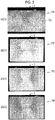
- FIG. 7 is a view illustrating an example of a joint obtained by performing the cold working step.
- the joint processing method of Embodiment 1 is processing performed in order to improve the quality of a joint formed by friction stir welding. As illustrated in FIG. 1 , the joint processing method performs a material placement step S1, a friction stir welding step S2, an anneal heat treatment step S3, a cold working step S4, a solution heat treatment step S5, and an aging heat treatment step S6 in order.
- a plate in which an aluminum alloy is used and configured as a metal material is applied.
- plates are placed such that a groove (a part to be welded) is formed by butting end surfaces of the plates against each other.
- the groove obtained by butting the end surfaces of the plates against each other is used as the part to be welded that is a target for friction stir welding.
- the invention is not particularly limited to this configuration, and arbitrary regions that become the target for friction stir welding may be adopted.
- a joint is formed by performing the friction stir welding (FSW) on the groove formed in the material placement step S1, and accordingly the butted plates are welded together.
- a friction stir welding device 1 is used, and perform the friction stir welding from both sides across the groove.
- the friction stir welding device 1 has a first rotation tool 21 and a second rotation tool 22 as welding tools.
- the first rotation tool 21 is disposed on an upper side (one side) in the thickness direction of the groove 6 across the groove 6.
- the first rotation tool 21 rotates about a first rotating axis I1, and is pressed against an upper surface of the groove 6.
- the second rotation tool 22 is disposed on a lower side (the other side) in the thickness direction of the groove 6 across the groove 6.
- the second rotation tool 22 rotates about a second rotating axis 12, and is pressed against a lower surface of the groove 6.
- the first rotation tool 21 is configured to include a first probe 32 and a first shoulder part 35.
- the first probe 32 is formed so as to become longer than half of the thickness of the groove 6. Additionally, a notch for stirring the metal of the softened groove 6 is formed in an outer peripheral surface of the first probe 32.
- the first shoulder part 35 is in contact with the upper surface of the groove 6.
- Such a first rotation tool 21 rotates the first shoulder part 35 in a state where the first shoulder part 35 is made to be in contact with the upper surface of the groove 6, thereby giving heat resulting from friction to the groove 6, and gives the heat, thereby stirring the softened groove 6 with the first probe 32.
- a first stirring region subjected to the friction stirring by the first rotation tool 21 is formed on the upper side of the groove 6.
- the second rotation tool 22 is configured to include a second probe 42 and a second shoulder part 45.
- the second probe 42 and the second shoulder part 45 are almost the same as those of the first rotation tool 21, the description thereof will be omitted.
- Such a second rotation tool 22 rotates the second shoulder part 45 in a state where the second shoulder part 45 is made to be in contact with the lower surface of the groove 6, thereby giving heat resulting from friction to the groove 6, and gives the heat, thereby stirring the softened groove 6 with the second probe 42.
- a second stirring region subjected to the friction stirring by the second rotation tool 22 is formed on the lower side of the groove 6.
- the first stirring region is a region that becomes longer than half of the thickness of the groove 6 from the upper surface of the groove 6.
- the second stirring region is a region that becomes longer than half of the thickness of the groove 6 from the lower surface of the groove 6.
- the first stirring region and the second stirring region are regions that overlap each other in the thickness direction of the groove 6.
- a region on the lower side of the first stirring region and a region on the upper side of the second stirring region are overlapping regions that overlap each other at the center of the groove 6 in its thickness direction.
- first rotation tool 21 and the second rotation tool 22 are disposed in an offset manner so as not to interfere with each other physically, and simultaneously perform welding from both sides of the groove 6.
- first rotation tool 21 and the second rotation tool 22 are disposed in an offset manner so as not to interfere with each other physically, and simultaneously perform welding from both sides of the groove 6.
- welding may be performed by the second rotation tool 22 after welding is performed by the first rotation tool 21, without simultaneously performing both sides of the groove 6.
- the friction stir temperature of the joint during the friction stir welding is a temperature between 400°C to 550°C in, for example, an 2219 aluminum alloy.
- a plate 5 including the joint formed in the friction stir welding step S2 is annealed at a predetermined annealing temperature.
- This anneal heat treatment step S3 is performed in order to make the hardness of the plate 5 uniform after the friction stir welding.
- a horizontal axis represents a distance from a center (0) of the welding width of the joint
- a vertical axis represents Vickers hardness (Hv).
- Hv Vickers hardness
- the hardness of the joint uniform is made uniform, so that local deformation of the plate 5 in which the joint is formed is suppressed during the cold working in the cold working step S4 that becomes a post-step, and it is possible to uniformly impart strain.
- the size of the grain size of the aluminum alloy in the joint 7 varies depending on the annealing temperature of the anneal heat treatment step S3.
- An item on the left side of FIG. 4 is the annealing temperature
- an item on the right side of FIG. 4 is a occurrence situation of enlargement in which the grain size becomes large.
- the joint 7 formed when the annealing temperature illustrated in FIG. 4 is 413°C becomes P1 illustrated in FIG. 5 .
- the annealing temperature in P1 is higher than a lower limit of the friction stir temperature.
- the annealing temperature in P2 is slightly lower than the friction stir temperature.
- the annealing temperature in P3 is lower than the friction stir temperature and is lower than the annealing temperature of P2.
- the annealing temperature in P4 is lower than the friction stir temperature and is lower than the annealing temperature of P3.
- the enlargement of the grains occurs in a region Ea at the center of the joint in its thickness direction and is as illustrated in FIG. 4 .
- the enlargement of the grains slightly decreases compared to than P1 at the center of the joint in its thickness direction and is as illustrated in FIG. 4 .
- the enlargement of the grains does not occur and is as illustrated in FIG. 4 .
- the plate 5 in which the joint 7 is formed is annealed at an annealing temperature lower than the friction stir temperature.
- the annealing temperature is lower than 400°C.
- the enlargement of the grains of the joint 7 can be more suitably suppressed by making the annealing temperature 10°C or more lower than the lower limit temperature of the friction stir temperature.
- the annealing temperature is made too low, annealing time taken in order to make the hardness of the plate 5 uniform becomes long. Therefore, it is preferable that the annealing temperature is equal to or higher than 350°C.
- the cold working is performed in a cold state on the joint 7 after the anneal heat treatment, under predetermined cold working conditions.
- the cold working conditions are conditions such that the grain size of the joint is equal to or smaller than the grain size of the aluminum alloy in the groove 6 before the friction stir welding step S2.
- a predetermined strain amount is given to the joint 7 by performing the cold working such that the thickness of the joint 7 becomes small.
- solution heat treatment step S5 solution heat treatment of the plate 5 including the joint 7 after the cold working is performed.
- the diameter of the grains formed in the joint 7 varies depending on the cold working conditions in the cold working step S4.
- a horizontal axis represents the strain amount
- a vertical axis represents the grain size.
- the strain amount is the deformation amount of the joint 7 before and after the cold working, for example, a ratio when the thickness of the joint 7 after the cold working becomes small, with respect to the thickness of the joint 7 before the cold working.
- the grain size of the groove 6 and a base material part before the friction stir welding is within a range of a region R.
- the grain size in the region R is between about 0.1 mm to about 0.15 mm.
- the cold working step S4 if a strain amount of 0% resulting from the cold working is given to the joint 7 (that is, the cold working is not performed), the grain size of the joint 7 reaches about 0.35 mm. For this reason, in a case where the strain amount is 0%, the grain size of the joint 7 becomes greater than the grain size of the region R. Thus, the grains (structure) of the joint 7 after the solution heat treatment are enlarged.
- the cold working step S4 if a strain amount of 5% resulting from the cold working is given to the joint 7, the grain size of the joint 7 reaches about 0.15 mm.
- the grain size of the joint 7 becomes the grain size within a range of the region R.
- the enlargement of the grains in the joint 7 after the solution heat treatment is suppressed.
- the grain size of the joint 7 becomes smaller than 0.1 mm. For this reason, in a case where the strain amount is 10% or more, the grain size of the joint 7 becomes smaller than the grain size of the region R, the grains in the joint 7 after the solution heat treatment are made fine.
- FIG. 7 is a view illustrating the joint 7 when the solution heat treatment is performed after the cold working is performed on a test piece W in which the joint 7 is formed by rolling under the cold working conditions such that the predetermined strain amount is obtained.
- the joint 7 when a strain amount of 0% is given thereto becomes P11 illustrated in FIG. 7
- the joint 7 when a strain amount of 5% is given thereto becomes P12 illustrated in FIG. 7
- the strain amount is 0%
- the enlargement of the structure is recognized.
- the cold working step S4 it is confirmed that the enlargement of the grains of the joint 7 can be suppressed by performing the cold working on the joint 7 under the cold working conditions such that the strain amount becomes equal to or more than 5%. For this reason, in the cold working step S4, the cold working is performed on the joint 7 under the cold working conditions such that the strain amount becomes equal to or more than 5%.
- the strain amount is set to be equal to or more than 10%, the structure also including the base material part becomes fine and becomes uniform, and a difference between the joint 7 and the base material part is no longer recognized.
- the hardness of the plate 5 is enhanced by performing artificial aging heat treatment on the plate 5 after the solution heat treatment.
- the plate 5 after the aging heat treatment step S6 becomes T6 having the quality of the aluminum alloy defined by Japanese Industrial Standard (JIS).
- JIS Japanese Industrial Standard
- the elongation amount of the material in the state of T6 is about 4% in a case where strain is not given, whereas an elongation of 8% or more is obtained in a case where a strain of 5% or larger at which the enlargement can be suppressed is given.
- a desired value at the standard value (AMS-QQ-A-250/30) of this material is equal to or more than 7%, and the standard value can be satisfied by giving strain before the solution heat treatment.
- FIG. 8 is a graph regarding the strain amount (plate thickness change) of the dome member to which the joint processing method is applied.
- FIGS. 9 and 10 are plan views illustrating the example of a plate that becomes a material of the dome member placed in the material placement step.
- FIG. 11 is a plan view illustrating a related-art example of a plate that becomes a material of a dome member.
- the dome member 51 is formed in the cold working step S4 of the joint processing method. That is, the dome member 51 is formed by performing the cold working on the plate 5 before the cold working. In the cold working step S4, the dome-shaped dome member 51 that curves from the center side of the plate 5 toward the outside thereof is formed by performing rotational cold working, so-called, spinning processing on the plate 5.
- the horizontal axis represents the position (radial position) of the dome member 51 in its radial direction and the vertical axis represents the strain amount.
- the strain amount becomes a ratio of the thickness after the cold working to the thickness before the cold working.
- a numerical value of the ratio is 1.00 and the strain amount becomes 0%.
- the strain amount becomes large from the center side of the dome member toward the outside thereof, and the strain amount becomes 5% at a position where the radial position becomes r1.
- a region Sa from the center side of the dome member to the radial position r1 is a region where the strain amount becomes smaller than 5%
- a region Sb from the radial position r1 to the outside is a region where the strain amount becomes equal to or more than 5%.
- FIGS. 9 and 10 illustrate the plate 5 before the cold working to be subjected to the friction stir welding.
- a region corresponding to the region Sa of the dome member 51 is formed on the center side, and a region corresponding to the region Sb of the dome member 51 is formed on the outside of the region Sa.
- the joint 7 formed in the plate 5 is formed in the region Sb.
- the plate 5 is configured using three workpieces W1 to W3. Specifically, a workpiece W1 among the three workpieces W1 to W3 has a size such that the region Sa falls therein, and this workpiece W1 is disposed at the center. The two remaining workpieces W2 and W3 are disposed on both sides of the workpiece W1, and accordingly, grooves 6 are respectively formed on both sides of the workpiece W1.
- the plate 5 in which joints 7 are formed in the region Sb by performing the friction stir welding on the two grooves 6 formed in both sides of the workpiece W1, respectively, can be obtained.
- the plate 5 in a case where joints 7 are formed in the region Sb, the plate 5 is configured using five workpieces W11 to W15. Specifically, a workpiece W11 among the five workpieces W11 to W15 has a size such that the region Sa falls therein, and this workpiece W11 is disposed at the center. The four remaining workpieces W12 to W15 are disposed around the workpiece W11, and accordingly, grooves 6 are respectively formed around of the workpiece W11.
- the plate 5 in which the joints 7 are formed in the region Sb by performing the friction stir welding on the four grooves 6 formed around the workpiece W11, respectively, can be obtained.
- a welding start point and a welding end point in the friction stir welding step S2 can be located in a region outside the dome member 51 formed during the spinning processing. For this reason, one side of the plate 5 having a rectangular shape can be made to have almost the same length as the diameter of the dome member 51.
- the plate 5 illustrated in FIG. 11 is disposed by butting two workpieces W21 and W22 with the same size against each other at the center of the plate 5.
- the joint 7 formed in the friction stir welding step S2 is formed in the region Sa.
- the joint formed in the region Sa does not receive strain required for suppressing the enlargement during the spinning processing, the enlargement of the structure cannot be prevented.
- the welding start point and the welding end point in the friction stir welding step S2 are located in the region outside the dome member 51 formed during the spinning processing, it is necessary to make one side of the plate 5 having a rectangular shape larger than the diameter of the dome member 51.
- the plate 5 illustrated in FIG. 11 becomes larger than the plates 5 illustrated in FIGS. 9 and 10 .
- nucleation sites for recrystallization can be increased in the joint 7 by performing the cold working step S4 on the joint 7 of the plate 5 formed in the friction stir welding step S2.
- the solution heat treatment step S5 is performed after the cold working step S4
- the growths of the nucleation sites for recrystallization can be suppressed each other by an amount equivalent to an increase in the nucleation sites for recrystallization. Therefore, the enlargement of the grains of the joint 7 can be suppressed, and the grains of the joint 7 can be made fine. In this way, a decrease in the quality of the joint 7 can be suppressed by making the grains of the joint 7 fine. Therefore, for example, even in a case where strain is imparted after the solution heat treatment in order to enhance the strength of the plate 5, it is possible to obtains quality capable of withstanding the cold working.
- the enlargement of the grains of the joint 7 are suitably suppressed by setting the cold working conditions to the conditions such that the strain amount of the joint before and after the cold working step S4 becomes equal to or more than 5%.
- the anneal heat treatment step S3 is performed, so that the hardness in the joint 7 of the plate 5 can be made uniform, and in the cold working step S4, the local deformation of the plate 5 can be suppressed, and strain can be uniformly imparted.
- the enlargement of the grains in the joint 7 can be suppressed by making the friction stir temperature high and making the annealing temperature low, in the anneal heat treatment step S3.
- the friction stir welding is performed from both sides of the groove 6, and the first stirring region formed by the first rotation tool 21 and the second stirring region formed by the second rotation tool 22 overlap with each other. For this reason, since the friction stirring is performed over the entire region in the thickness direction of the joint 7, heat input to the joint 7 resulting from the friction stirring is performed over the entire region in the thickness direction.
- the hardness of the plate 5 can be enhanced by performing the aging heat treatment step S6 after the cold working step S4 is formed in the cold state and the solution heat treatment step S5 is performed.
- T6 having the quality of the aluminum alloy defined by Japanese Industrial Standard (JIS) even in a case where the joint 7 is formed in the plate 5 can be obtained.
- JIS Japanese Industrial Standard
- the plate 5 is formed in the dome member 51 while giving strain to the plate 5 by performing the rotational cold working in the cold working step S4. Therefore, the plate 5 can be worked in a dome shape while suppressing the enlargement of the grains.
- the cold working step S4 can be performed in the cold state. Therefore, the cold working to the joint 7 can be appropriately performed while appropriately controlling the strain amount to be given to the joint 7. Additionally, in a case where temperature is equal to or lower than 100°C, a recovery phenomenon or the like does not occur. Therefore, a phenomenon in which the strain put in during the cold working is got rid of during working also does not occur, and the amount of the nucleation sites for recrystallization for suppressing the enlargement can also be controlled.
- the anneal heat treatment step S3 is provided. However, in a case where the hardness of the joint 7 after the friction stir welding step S2 becomes uniform or in a case where a harness difference hardness does not have a bad influence on the cold working step S4, the anneal heat treatment step S3 may be skipped.
- the annealing temperature is made lower than the friction stir temperature.
- the friction stir temperature may be made high during the friction stir welding, the annealing temperature may be made low during the anneal heat treatment step, or both may be performed.
- the invention is not particularly limited.
- a heating source that heats the groove 6 may be provided on the back side of a welding tool in the thickness direction of the groove 6.
- the friction stir temperature of the joint 7 can be made high by heating the joint 7 with the heating source.
- the annealing temperature can be set to be high. Therefore, the annealing time can be shortened, and working efficiency can be enhanced.
- FIG. 12 is a flowchart regarding the joint processing method related to Embodiment 2.
- portions different from Embodiment 1 will be described in order to avoid duplicate description, and portions having the same configurations as Embodiment 1 will be designated by the same reference signs.
- a strain imparting step S7 is performed after the solution heat treatment between the solution heat treatment step S5 and the aging heat treatment step S6 of the joint processing method of Embodiment 1.
- the joint processing method related to Embodiment 2 will be described.
- the strain imparting step S7 is performed before the aging heat treatment step S6 after the solution heat treatment step S5.
- the strength of the plate 5 is improved by performing the cold working in the cold state on the plate 5 after the solution heat treatment.
- the strain amount to be given to the plate 5 in the strain imparting step S7 is within a range of 2% to 8%, and higher strength is obtained after the aging heat treatment as the strain amount is larger.
- the strength of the plate 5 can be enhanced by further performing the strain imparting step S7 in the cold state and performing the aging heat treatment step S6 after the cold working step S4 is performed in the cold state and the solution heat treatment step S5 is performed.
- T8 having the quality of the aluminum alloy defined by Japanese Industrial Standard (JIS) even in a case where the joint 7 is formed in the plate 5 can be obtained. This is because, since the grains in the joint 7 after the solution heat treatment are not enlarged, the joint 7 has quality capable of withstanding processing even in a case where impartment of higher strain is performed.
- FIG. 13 is an explanatory view illustrating the joint processing method related to Embodiment 3.
- portions different from Embodiments 1 and 2 will be described in order to avoid duplicate description, and portions having the same configurations as Embodiments 1 and 2 will be designated by the same reference signs.
- the thickness of the joint 7 is made larger than the thickness of regions other than the joint.
- the joint processing method related to Embodiment 3 will be described.
- the thickens of an end part 5a that faces another plate 5 to be butted against the plate 5 is made large (S101). Meanwhile, the thickness of a part 5b other than the end part 5a is made smaller than the thickness of the end part 5a.
- the joint 7 is formed by performing the friction stir welding on the groove 6 formed by the end part 5a of one plate 5 and the end part 5a of the other plate 5, from both sides in the thickness direction of the groove 6, using the first rotation tool 21 and the second rotation tool 22 (S102).
- the thickness of the joint 7 formed by the friction stir welding step S2 becomes larger than the thickness of portions other than the joint 7.
- the joint 7 is subjected to the cold working such that the thickness of the joint 7 becomes small, by performing press forming using an upper die 61 and a lower die 62 from both sides in the thickness direction (S103).
- the cold working step S4 the cold working is performed such that the thickness of the joint 7 becomes small. Accordingly, the thickness of the joint 7 and the thickness of regions other than the joint 7 can be made to be the same thickness while suppressing the enlargement of the grains in the joint 7.
- a forging step may be performed.
- the cold working by giving pressure to the joint 7 two or more times using a hammer or the like, the cold working may be performed such that a dead metal region is not formed.
Landscapes
- Engineering & Computer Science (AREA)
- Mechanical Engineering (AREA)
- Chemical & Material Sciences (AREA)
- General Engineering & Computer Science (AREA)
- Physics & Mathematics (AREA)
- Thermal Sciences (AREA)
- Crystallography & Structural Chemistry (AREA)
- Materials Engineering (AREA)
- Metallurgy (AREA)
- Organic Chemistry (AREA)
- Pressure Welding/Diffusion-Bonding (AREA)
Applications Claiming Priority (2)
| Application Number | Priority Date | Filing Date | Title |
|---|---|---|---|
| JP2014194396A JP6403515B2 (ja) | 2014-09-24 | 2014-09-24 | 接合部処理方法及びドーム部材 |
| PCT/JP2015/074846 WO2016047394A1 (ja) | 2014-09-24 | 2015-09-01 | 接合部処理方法及びドーム部材 |
Publications (3)
| Publication Number | Publication Date |
|---|---|
| EP3159091A1 EP3159091A1 (en) | 2017-04-26 |
| EP3159091A4 EP3159091A4 (en) | 2017-08-23 |
| EP3159091B1 true EP3159091B1 (en) | 2020-07-29 |
Family
ID=55580922
Family Applications (1)
| Application Number | Title | Priority Date | Filing Date |
|---|---|---|---|
| EP15845443.9A Active EP3159091B1 (en) | 2014-09-24 | 2015-09-01 | Joint processing method and dome member |
Country Status (4)
| Country | Link |
|---|---|
| US (1) | US10512985B2 (https=) |
| EP (1) | EP3159091B1 (https=) |
| JP (1) | JP6403515B2 (https=) |
| WO (1) | WO2016047394A1 (https=) |
Families Citing this family (8)
| Publication number | Priority date | Publication date | Assignee | Title |
|---|---|---|---|---|
| JP6332562B2 (ja) * | 2016-03-31 | 2018-05-30 | Jfeスチール株式会社 | 構造用鋼の摩擦撹拌接合方法及び装置 |
| WO2019026864A1 (ja) | 2017-08-01 | 2019-02-07 | Jfeスチール株式会社 | 金属板の両面摩擦撹拌接合方法および両面摩擦撹拌接合装置 |
| EP3653329B1 (en) * | 2017-09-13 | 2023-10-11 | JFE Steel Corporation | Double-sided friction stir welding method for metal plate |
| JP7118688B2 (ja) * | 2018-03-28 | 2022-08-16 | 三菱重工業株式会社 | 被加工物の加工方法及び加工装置 |
| WO2022010718A1 (en) * | 2020-07-09 | 2022-01-13 | Lam Research Corporation | Friction stir processing for corrosion resistance |
| JP7452496B2 (ja) * | 2021-06-07 | 2024-03-19 | 日本軽金属株式会社 | 接合体の製造方法および接合装置 |
| CN115572981B (zh) * | 2022-09-09 | 2024-06-11 | 常熟市常沪螺母制造有限公司 | 金属冷镦线材表面结晶工艺生产线 |
| CN119772514A (zh) * | 2024-12-17 | 2025-04-08 | 中国科学院金属研究所 | 一种铝合金件及其制备方法 |
Citations (1)
| Publication number | Priority date | Publication date | Assignee | Title |
|---|---|---|---|---|
| US5460317A (en) * | 1991-12-06 | 1995-10-24 | The Welding Institute | Friction welding |
Family Cites Families (38)
| Publication number | Priority date | Publication date | Assignee | Title |
|---|---|---|---|---|
| US3024938A (en) * | 1959-07-27 | 1962-03-13 | Budd Co | Sectional pressure vessel and method of making it |
| JPS4838388B1 (https=) * | 1969-03-28 | 1973-11-16 | ||
| US5098490A (en) * | 1990-10-05 | 1992-03-24 | Shin Huu | Super position aluminum alloy can stock manufacturing process |
| US5152452A (en) * | 1992-03-10 | 1992-10-06 | York Industries, Inc. | Pressure vessel and method |
| US5697511A (en) * | 1996-09-27 | 1997-12-16 | Boeing North American, Inc. | Tank and method of fabrication |
| JP4008535B2 (ja) * | 1997-07-07 | 2007-11-14 | 昭和電工株式会社 | 摩擦撹拌接合装置及び摩擦撹拌接合方法 |
| US6258463B1 (en) * | 2000-03-02 | 2001-07-10 | Praxair S.T. Technology, Inc. | Anodized cryogenically treated aluminum |
| JP4749570B2 (ja) * | 2001-03-07 | 2011-08-17 | 本田技研工業株式会社 | 摩擦撹拌接合法 |
| EP2080579A1 (en) * | 2001-03-07 | 2009-07-22 | Showa Denko K.K. | Friction agitation joining method, method for manufacturing joined butted members, and friction agitation joining apparatus |
| US6660106B1 (en) | 2001-08-22 | 2003-12-09 | The Boeing Company | Methods of manufacture of spin-forming blanks, particularly for fabrication of rocket domes |
| JP4008256B2 (ja) * | 2002-02-15 | 2007-11-14 | 三菱重工業株式会社 | アルミ合金製圧力容器に使用するドームの製造方法 |
| KR101067033B1 (ko) * | 2003-04-25 | 2011-09-22 | 혼다 기켄 고교 가부시키가이샤 | 튜브형 금속 본체 및 그 제조 방법 그리고 압력 용기를위한 라이너 및 그 제조 방법 |
| FR2855083B1 (fr) * | 2003-05-20 | 2006-05-26 | Pechiney Rhenalu | Procede de fabrication de pieces en alliage d'aluminium soudees par friction |
| JP4436148B2 (ja) * | 2004-02-09 | 2010-03-24 | 本田技研工業株式会社 | 圧力容器用ライナおよびその製造方法 |
| US20080274383A1 (en) * | 2004-04-08 | 2008-11-06 | Showa Denko K.K. | Process for Fabricating Pressure Vessel Liner |
| US7971740B2 (en) * | 2004-07-06 | 2011-07-05 | Honda Motor Co., Ltd. | Pressure vessel |
| JP2007190606A (ja) * | 2006-01-19 | 2007-08-02 | Susumu Hioki | 加熱摩擦攪拌溶接方法および装置 |
| WO2007111325A1 (ja) * | 2006-03-28 | 2007-10-04 | Showa Denko K.K. | ライナ構成部材の製造方法 |
| US20080277036A1 (en) | 2007-05-11 | 2008-11-13 | Luxfer Group Limited | Method for manufacturing tanks |
| US8079126B2 (en) * | 2008-01-25 | 2011-12-20 | Pratt & Whitney Rocketdyne, Inc. | Friction stir welded bladder fuel tank |
| JP5212163B2 (ja) * | 2008-03-11 | 2013-06-19 | 日本軽金属株式会社 | 摩擦攪拌用回転ツール及び接合方法 |
| JP2008279509A (ja) * | 2008-07-14 | 2008-11-20 | Showa Denko Kk | 接合継手の製造方法 |
| JP4911157B2 (ja) * | 2008-10-29 | 2012-04-04 | 日本軽金属株式会社 | 厚肉被接合材の接合方法及び接合構造 |
| FR2945464B1 (fr) * | 2009-05-13 | 2012-03-23 | Alcan Rhenalu | Procede d'assemblage par soudage de pieces en alliage d'aluminium. |
| JP5074456B2 (ja) * | 2009-06-03 | 2012-11-14 | 本田技研工業株式会社 | 車両用強度部材 |
| US8728389B2 (en) * | 2009-09-01 | 2014-05-20 | United Technologies Corporation | Fabrication of L12 aluminum alloy tanks and other vessels by roll forming, spin forming, and friction stir welding |
| JP4838388B2 (ja) * | 2009-11-18 | 2011-12-14 | 三菱日立製鉄機械株式会社 | 両面摩擦攪拌接合方法および装置並びに両面摩擦攪拌接合用ツールセット |
| US20120031249A1 (en) * | 2010-08-06 | 2012-02-09 | Osaka Municipal Technical Research Institute | Method for refining texture of ferrous material, and ferrous material and blade having microscopic texture |
| WO2012029176A1 (ja) * | 2010-09-03 | 2012-03-08 | 三菱日立製鉄機械株式会社 | 摩擦攪拌接合システムおよび摩擦攪拌接合方法 |
| US9090950B2 (en) | 2010-10-13 | 2015-07-28 | The United States Of America As Represented By The Administrator Of The National Aeronautics And Space Administration | Abnormal grain growth suppression in aluminum alloys |
| JP2014040621A (ja) * | 2012-08-21 | 2014-03-06 | Mitsubishi Heavy Ind Ltd | 鏡板の製造方法 |
| EP2937435B1 (en) * | 2012-12-21 | 2024-06-12 | Kawasaki Jukogyo Kabushiki Kaisha | Method of manufacturing a frame made of aluminum alloy for aircraft use |
| JP6155155B2 (ja) * | 2013-09-27 | 2017-06-28 | 三菱重工業株式会社 | 摩擦撹拌工具、摩擦撹拌接合装置及び摩擦撹拌接合方法 |
| WO2015069376A1 (en) * | 2013-11-08 | 2015-05-14 | United Technologies Corporation | High conformal pressure vessel |
| JP6284444B2 (ja) * | 2014-06-25 | 2018-02-28 | 三菱重工業株式会社 | 摩擦撹拌接合方法及び摩擦撹拌接合装置 |
| BR112017007186B1 (pt) * | 2014-10-07 | 2022-03-03 | United Technologies Corporation | Conjunto de recipiente de pressão, e, método para formação de um conjunto de recipiente de pressão |
| EP3204683B1 (en) * | 2014-10-07 | 2020-09-02 | United Technologies Corporation | Pressure vessel fluid manifold assembly |
| KR102098217B1 (ko) * | 2016-03-31 | 2020-04-07 | 제이에프이 스틸 가부시키가이샤 | 구조용 강의 마찰 교반 접합 방법 및 장치 |
-
2014
- 2014-09-24 JP JP2014194396A patent/JP6403515B2/ja active Active
-
2015
- 2015-09-01 WO PCT/JP2015/074846 patent/WO2016047394A1/ja not_active Ceased
- 2015-09-01 US US15/328,662 patent/US10512985B2/en active Active
- 2015-09-01 EP EP15845443.9A patent/EP3159091B1/en active Active
Patent Citations (2)
| Publication number | Priority date | Publication date | Assignee | Title |
|---|---|---|---|---|
| US5460317A (en) * | 1991-12-06 | 1995-10-24 | The Welding Institute | Friction welding |
| US5460317B1 (en) * | 1991-12-06 | 1997-12-09 | Welding Inst | Friction welding |
Also Published As
| Publication number | Publication date |
|---|---|
| WO2016047394A1 (ja) | 2016-03-31 |
| US10512985B2 (en) | 2019-12-24 |
| JP2016064426A (ja) | 2016-04-28 |
| EP3159091A1 (en) | 2017-04-26 |
| US20170209957A1 (en) | 2017-07-27 |
| EP3159091A4 (en) | 2017-08-23 |
| JP6403515B2 (ja) | 2018-10-10 |
Similar Documents
| Publication | Publication Date | Title |
|---|---|---|
| EP3159091B1 (en) | Joint processing method and dome member | |
| US12186828B2 (en) | Double-sided friction stir welding method, methods for producing cold-rolled steel strip and coated steel strip, double-sided friction stir welding apparatus, and facilities for producing cold-rolled steel strip and coated steel strip | |
| EP2769797B1 (en) | Resistance spot welding method for high-tensile steel plates, and resistance spot welding joint | |
| KR101521039B1 (ko) | 단차가 형성된 단조재의 제조 방법 | |
| RU2675889C2 (ru) | Способ производства паяного соединения и паяное соединение | |
| RU2709321C1 (ru) | Способ изготовления холоднокатаных сварных стальных листов и листы, произведенные таким образом | |
| US10022816B2 (en) | Friction welding method | |
| EP3150325B1 (en) | Joining structure for member in motor vehicle body | |
| US20190009367A1 (en) | Method of manufacturing press formed product | |
| JP7237961B2 (ja) | アルミニウム合金部品の溶接後熱処理のための方法及び装置並びにその方法に従って処理された溶接されたアルミニウム部品 | |
| KR20140069875A (ko) | 고강도-고연성 층상복합알루미늄합금판재 | |
| JP5033423B2 (ja) | 圧入接合における熱処理方法 | |
| CN110125522B (zh) | 一种近α相钛合金固态焊接焊缝组织等轴化处理方法 | |
| CN105848823A (zh) | 适于在用于无级变速器的传动带中使用的承载环的制造方法 | |
| Ciccarelli et al. | In-process control of rotational speed in friction stir welding of sheet blanks with variable mechanical properties | |
| US11299794B2 (en) | Hot-forming line and method for producing hot-formed and press-quenched sheet-steel products | |
| KR102619894B1 (ko) | 강판 및 부재 | |
| RU2709908C1 (ru) | Способ получения сварных соединений термоупрочняемых алюминиевых сплавов с высоким пределом выносливости | |
| JP2006218500A (ja) | 薄鋼板のレーザー突合せ溶接鋼板およびその溶接方法 | |
| JP6799278B2 (ja) | レーザ溶接方法 | |
| KR20130064577A (ko) | 모넬 금속에 대한 단조 가공 방법 | |
| CN101018875A (zh) | 钢材的热处理方法 | |
| JP2025108703A (ja) | 異種金属接合材 | |
| JP2014024089A (ja) | 電子ビーム溶接方法 | |
| JP6223934B2 (ja) | 電子ビーム溶接方法、電子ビーム溶接構造物の製造方法および電子ビーム溶接構造物 |
Legal Events
| Date | Code | Title | Description |
|---|---|---|---|
| STAA | Information on the status of an ep patent application or granted ep patent |
Free format text: STATUS: THE INTERNATIONAL PUBLICATION HAS BEEN MADE |
|
| PUAI | Public reference made under article 153(3) epc to a published international application that has entered the european phase |
Free format text: ORIGINAL CODE: 0009012 |
|
| STAA | Information on the status of an ep patent application or granted ep patent |
Free format text: STATUS: REQUEST FOR EXAMINATION WAS MADE |
|
| 17P | Request for examination filed |
Effective date: 20170123 |
|
| AK | Designated contracting states |
Kind code of ref document: A1 Designated state(s): AL AT BE BG CH CY CZ DE DK EE ES FI FR GB GR HR HU IE IS IT LI LT LU LV MC MK MT NL NO PL PT RO RS SE SI SK SM TR |
|
| AX | Request for extension of the european patent |
Extension state: BA ME |
|
| A4 | Supplementary search report drawn up and despatched |
Effective date: 20170720 |
|
| RIC1 | Information provided on ipc code assigned before grant |
Ipc: C22F 1/04 20060101ALI20170714BHEP Ipc: B21D 22/14 20060101ALI20170714BHEP Ipc: B23K 103/10 20060101ALN20170714BHEP Ipc: B23K 20/12 20060101AFI20170714BHEP |
|
| DAV | Request for validation of the european patent (deleted) | ||
| DAX | Request for extension of the european patent (deleted) | ||
| TPAC | Observations filed by third parties |
Free format text: ORIGINAL CODE: EPIDOSNTIPA |
|
| STAA | Information on the status of an ep patent application or granted ep patent |
Free format text: STATUS: EXAMINATION IS IN PROGRESS |
|
| 17Q | First examination report despatched |
Effective date: 20180719 |
|
| TPAC | Observations filed by third parties |
Free format text: ORIGINAL CODE: EPIDOSNTIPA |
|
| GRAP | Despatch of communication of intention to grant a patent |
Free format text: ORIGINAL CODE: EPIDOSNIGR1 |
|
| STAA | Information on the status of an ep patent application or granted ep patent |
Free format text: STATUS: GRANT OF PATENT IS INTENDED |
|
| RIC1 | Information provided on ipc code assigned before grant |
Ipc: B21D 22/14 20060101ALI20200123BHEP Ipc: B23K 103/10 20060101ALN20200123BHEP Ipc: C22F 1/04 20060101ALI20200123BHEP Ipc: B23K 20/12 20060101AFI20200123BHEP |
|
| INTG | Intention to grant announced |
Effective date: 20200211 |
|
| GRAS | Grant fee paid |
Free format text: ORIGINAL CODE: EPIDOSNIGR3 |
|
| GRAA | (expected) grant |
Free format text: ORIGINAL CODE: 0009210 |
|
| STAA | Information on the status of an ep patent application or granted ep patent |
Free format text: STATUS: THE PATENT HAS BEEN GRANTED |
|
| AK | Designated contracting states |
Kind code of ref document: B1 Designated state(s): AL AT BE BG CH CY CZ DE DK EE ES FI FR GB GR HR HU IE IS IT LI LT LU LV MC MK MT NL NO PL PT RO RS SE SI SK SM TR |
|
| REG | Reference to a national code |
Ref country code: CH Ref legal event code: EP |
|
| REG | Reference to a national code |
Ref country code: DE Ref legal event code: R096 Ref document number: 602015056654 Country of ref document: DE |
|
| REG | Reference to a national code |
Ref country code: AT Ref legal event code: REF Ref document number: 1295229 Country of ref document: AT Kind code of ref document: T Effective date: 20200815 |
|
| REG | Reference to a national code |
Ref country code: IE Ref legal event code: FG4D |
|
| REG | Reference to a national code |
Ref country code: LT Ref legal event code: MG4D |
|
| REG | Reference to a national code |
Ref country code: NL Ref legal event code: MP Effective date: 20200729 |
|
| REG | Reference to a national code |
Ref country code: AT Ref legal event code: MK05 Ref document number: 1295229 Country of ref document: AT Kind code of ref document: T Effective date: 20200729 |
|
| PG25 | Lapsed in a contracting state [announced via postgrant information from national office to epo] |
Ref country code: ES Free format text: LAPSE BECAUSE OF FAILURE TO SUBMIT A TRANSLATION OF THE DESCRIPTION OR TO PAY THE FEE WITHIN THE PRESCRIBED TIME-LIMIT Effective date: 20200729 Ref country code: BG Free format text: LAPSE BECAUSE OF FAILURE TO SUBMIT A TRANSLATION OF THE DESCRIPTION OR TO PAY THE FEE WITHIN THE PRESCRIBED TIME-LIMIT Effective date: 20201029 Ref country code: PT Free format text: LAPSE BECAUSE OF FAILURE TO SUBMIT A TRANSLATION OF THE DESCRIPTION OR TO PAY THE FEE WITHIN THE PRESCRIBED TIME-LIMIT Effective date: 20201130 Ref country code: SE Free format text: LAPSE BECAUSE OF FAILURE TO SUBMIT A TRANSLATION OF THE DESCRIPTION OR TO PAY THE FEE WITHIN THE PRESCRIBED TIME-LIMIT Effective date: 20200729 Ref country code: HR Free format text: LAPSE BECAUSE OF FAILURE TO SUBMIT A TRANSLATION OF THE DESCRIPTION OR TO PAY THE FEE WITHIN THE PRESCRIBED TIME-LIMIT Effective date: 20200729 Ref country code: GR Free format text: LAPSE BECAUSE OF FAILURE TO SUBMIT A TRANSLATION OF THE DESCRIPTION OR TO PAY THE FEE WITHIN THE PRESCRIBED TIME-LIMIT Effective date: 20201030 Ref country code: FI Free format text: LAPSE BECAUSE OF FAILURE TO SUBMIT A TRANSLATION OF THE DESCRIPTION OR TO PAY THE FEE WITHIN THE PRESCRIBED TIME-LIMIT Effective date: 20200729 Ref country code: LT Free format text: LAPSE BECAUSE OF FAILURE TO SUBMIT A TRANSLATION OF THE DESCRIPTION OR TO PAY THE FEE WITHIN THE PRESCRIBED TIME-LIMIT Effective date: 20200729 Ref country code: NO Free format text: LAPSE BECAUSE OF FAILURE TO SUBMIT A TRANSLATION OF THE DESCRIPTION OR TO PAY THE FEE WITHIN THE PRESCRIBED TIME-LIMIT Effective date: 20201029 Ref country code: AT Free format text: LAPSE BECAUSE OF FAILURE TO SUBMIT A TRANSLATION OF THE DESCRIPTION OR TO PAY THE FEE WITHIN THE PRESCRIBED TIME-LIMIT Effective date: 20200729 |
|
| PG25 | Lapsed in a contracting state [announced via postgrant information from national office to epo] |
Ref country code: PL Free format text: LAPSE BECAUSE OF FAILURE TO SUBMIT A TRANSLATION OF THE DESCRIPTION OR TO PAY THE FEE WITHIN THE PRESCRIBED TIME-LIMIT Effective date: 20200729 Ref country code: RS Free format text: LAPSE BECAUSE OF FAILURE TO SUBMIT A TRANSLATION OF THE DESCRIPTION OR TO PAY THE FEE WITHIN THE PRESCRIBED TIME-LIMIT Effective date: 20200729 Ref country code: LV Free format text: LAPSE BECAUSE OF FAILURE TO SUBMIT A TRANSLATION OF THE DESCRIPTION OR TO PAY THE FEE WITHIN THE PRESCRIBED TIME-LIMIT Effective date: 20200729 Ref country code: IS Free format text: LAPSE BECAUSE OF FAILURE TO SUBMIT A TRANSLATION OF THE DESCRIPTION OR TO PAY THE FEE WITHIN THE PRESCRIBED TIME-LIMIT Effective date: 20201129 |
|
| PG25 | Lapsed in a contracting state [announced via postgrant information from national office to epo] |
Ref country code: NL Free format text: LAPSE BECAUSE OF FAILURE TO SUBMIT A TRANSLATION OF THE DESCRIPTION OR TO PAY THE FEE WITHIN THE PRESCRIBED TIME-LIMIT Effective date: 20200729 |
|
| PG25 | Lapsed in a contracting state [announced via postgrant information from national office to epo] |
Ref country code: MC Free format text: LAPSE BECAUSE OF FAILURE TO SUBMIT A TRANSLATION OF THE DESCRIPTION OR TO PAY THE FEE WITHIN THE PRESCRIBED TIME-LIMIT Effective date: 20200729 Ref country code: EE Free format text: LAPSE BECAUSE OF FAILURE TO SUBMIT A TRANSLATION OF THE DESCRIPTION OR TO PAY THE FEE WITHIN THE PRESCRIBED TIME-LIMIT Effective date: 20200729 Ref country code: RO Free format text: LAPSE BECAUSE OF FAILURE TO SUBMIT A TRANSLATION OF THE DESCRIPTION OR TO PAY THE FEE WITHIN THE PRESCRIBED TIME-LIMIT Effective date: 20200729 Ref country code: SM Free format text: LAPSE BECAUSE OF FAILURE TO SUBMIT A TRANSLATION OF THE DESCRIPTION OR TO PAY THE FEE WITHIN THE PRESCRIBED TIME-LIMIT Effective date: 20200729 Ref country code: CZ Free format text: LAPSE BECAUSE OF FAILURE TO SUBMIT A TRANSLATION OF THE DESCRIPTION OR TO PAY THE FEE WITHIN THE PRESCRIBED TIME-LIMIT Effective date: 20200729 Ref country code: DK Free format text: LAPSE BECAUSE OF FAILURE TO SUBMIT A TRANSLATION OF THE DESCRIPTION OR TO PAY THE FEE WITHIN THE PRESCRIBED TIME-LIMIT Effective date: 20200729 Ref country code: IT Free format text: LAPSE BECAUSE OF FAILURE TO SUBMIT A TRANSLATION OF THE DESCRIPTION OR TO PAY THE FEE WITHIN THE PRESCRIBED TIME-LIMIT Effective date: 20200729 |
|
| REG | Reference to a national code |
Ref country code: CH Ref legal event code: PL Ref country code: DE Ref legal event code: R097 Ref document number: 602015056654 Country of ref document: DE |
|
| PG25 | Lapsed in a contracting state [announced via postgrant information from national office to epo] |
Ref country code: AL Free format text: LAPSE BECAUSE OF FAILURE TO SUBMIT A TRANSLATION OF THE DESCRIPTION OR TO PAY THE FEE WITHIN THE PRESCRIBED TIME-LIMIT Effective date: 20200729 |
|
| PLBE | No opposition filed within time limit |
Free format text: ORIGINAL CODE: 0009261 |
|
| STAA | Information on the status of an ep patent application or granted ep patent |
Free format text: STATUS: NO OPPOSITION FILED WITHIN TIME LIMIT |
|
| REG | Reference to a national code |
Ref country code: BE Ref legal event code: MM Effective date: 20200930 |
|
| GBPC | Gb: european patent ceased through non-payment of renewal fee |
Effective date: 20201029 |
|
| PG25 | Lapsed in a contracting state [announced via postgrant information from national office to epo] |
Ref country code: LU Free format text: LAPSE BECAUSE OF NON-PAYMENT OF DUE FEES Effective date: 20200901 Ref country code: SK Free format text: LAPSE BECAUSE OF FAILURE TO SUBMIT A TRANSLATION OF THE DESCRIPTION OR TO PAY THE FEE WITHIN THE PRESCRIBED TIME-LIMIT Effective date: 20200729 |
|
| 26N | No opposition filed |
Effective date: 20210430 |
|
| PG25 | Lapsed in a contracting state [announced via postgrant information from national office to epo] |
Ref country code: CH Free format text: LAPSE BECAUSE OF NON-PAYMENT OF DUE FEES Effective date: 20200930 Ref country code: BE Free format text: LAPSE BECAUSE OF NON-PAYMENT OF DUE FEES Effective date: 20200930 Ref country code: SI Free format text: LAPSE BECAUSE OF FAILURE TO SUBMIT A TRANSLATION OF THE DESCRIPTION OR TO PAY THE FEE WITHIN THE PRESCRIBED TIME-LIMIT Effective date: 20200729 Ref country code: GB Free format text: LAPSE BECAUSE OF NON-PAYMENT OF DUE FEES Effective date: 20201029 Ref country code: LI Free format text: LAPSE BECAUSE OF NON-PAYMENT OF DUE FEES Effective date: 20200930 Ref country code: IE Free format text: LAPSE BECAUSE OF NON-PAYMENT OF DUE FEES Effective date: 20200901 |
|
| PG25 | Lapsed in a contracting state [announced via postgrant information from national office to epo] |
Ref country code: TR Free format text: LAPSE BECAUSE OF FAILURE TO SUBMIT A TRANSLATION OF THE DESCRIPTION OR TO PAY THE FEE WITHIN THE PRESCRIBED TIME-LIMIT Effective date: 20200729 Ref country code: MT Free format text: LAPSE BECAUSE OF FAILURE TO SUBMIT A TRANSLATION OF THE DESCRIPTION OR TO PAY THE FEE WITHIN THE PRESCRIBED TIME-LIMIT Effective date: 20200729 Ref country code: CY Free format text: LAPSE BECAUSE OF FAILURE TO SUBMIT A TRANSLATION OF THE DESCRIPTION OR TO PAY THE FEE WITHIN THE PRESCRIBED TIME-LIMIT Effective date: 20200729 |
|
| PG25 | Lapsed in a contracting state [announced via postgrant information from national office to epo] |
Ref country code: MK Free format text: LAPSE BECAUSE OF FAILURE TO SUBMIT A TRANSLATION OF THE DESCRIPTION OR TO PAY THE FEE WITHIN THE PRESCRIBED TIME-LIMIT Effective date: 20200729 |
|
| PGFP | Annual fee paid to national office [announced via postgrant information from national office to epo] |
Ref country code: DE Payment date: 20250730 Year of fee payment: 11 |
|
| PGFP | Annual fee paid to national office [announced via postgrant information from national office to epo] |
Ref country code: FR Payment date: 20250808 Year of fee payment: 11 |