WO2016047394A1 - 接合部処理方法及びドーム部材 - Google Patents
接合部処理方法及びドーム部材 Download PDFInfo
- Publication number
- WO2016047394A1 WO2016047394A1 PCT/JP2015/074846 JP2015074846W WO2016047394A1 WO 2016047394 A1 WO2016047394 A1 WO 2016047394A1 JP 2015074846 W JP2015074846 W JP 2015074846W WO 2016047394 A1 WO2016047394 A1 WO 2016047394A1
- Authority
- WO
- WIPO (PCT)
- Prior art keywords
- joint
- plastic working
- friction stir
- stir welding
- metal material
- Prior art date
- Legal status (The legal status is an assumption and is not a legal conclusion. Google has not performed a legal analysis and makes no representation as to the accuracy of the status listed.)
- Ceased
Links
Images





Classifications
-
- B—PERFORMING OPERATIONS; TRANSPORTING
- B23—MACHINE TOOLS; METAL-WORKING NOT OTHERWISE PROVIDED FOR
- B23K—SOLDERING OR UNSOLDERING; WELDING; CLADDING OR PLATING BY SOLDERING OR WELDING; CUTTING BY APPLYING HEAT LOCALLY, e.g. FLAME CUTTING; WORKING BY LASER BEAM
- B23K20/00—Non-electric welding by applying impact or other pressure, with or without the application of heat, e.g. cladding or plating
- B23K20/12—Non-electric welding by applying impact or other pressure, with or without the application of heat, e.g. cladding or plating the heat being generated by friction; Friction welding
- B23K20/122—Non-electric welding by applying impact or other pressure, with or without the application of heat, e.g. cladding or plating the heat being generated by friction; Friction welding using a non-consumable tool, e.g. friction stir welding
-
- B—PERFORMING OPERATIONS; TRANSPORTING
- B23—MACHINE TOOLS; METAL-WORKING NOT OTHERWISE PROVIDED FOR
- B23K—SOLDERING OR UNSOLDERING; WELDING; CLADDING OR PLATING BY SOLDERING OR WELDING; CUTTING BY APPLYING HEAT LOCALLY, e.g. FLAME CUTTING; WORKING BY LASER BEAM
- B23K20/00—Non-electric welding by applying impact or other pressure, with or without the application of heat, e.g. cladding or plating
- B23K20/12—Non-electric welding by applying impact or other pressure, with or without the application of heat, e.g. cladding or plating the heat being generated by friction; Friction welding
- B23K20/122—Non-electric welding by applying impact or other pressure, with or without the application of heat, e.g. cladding or plating the heat being generated by friction; Friction welding using a non-consumable tool, e.g. friction stir welding
- B23K20/1275—Non-electric welding by applying impact or other pressure, with or without the application of heat, e.g. cladding or plating the heat being generated by friction; Friction welding using a non-consumable tool, e.g. friction stir welding involving metallurgical change
-
- B—PERFORMING OPERATIONS; TRANSPORTING
- B21—MECHANICAL METAL-WORKING WITHOUT ESSENTIALLY REMOVING MATERIAL; PUNCHING METAL
- B21D—WORKING OR PROCESSING OF SHEET METAL OR METAL TUBES, RODS OR PROFILES WITHOUT ESSENTIALLY REMOVING MATERIAL; PUNCHING METAL
- B21D22/00—Shaping without cutting, by stamping, spinning, or deep-drawing
- B21D22/14—Spinning
-
- B—PERFORMING OPERATIONS; TRANSPORTING
- B23—MACHINE TOOLS; METAL-WORKING NOT OTHERWISE PROVIDED FOR
- B23K—SOLDERING OR UNSOLDERING; WELDING; CLADDING OR PLATING BY SOLDERING OR WELDING; CUTTING BY APPLYING HEAT LOCALLY, e.g. FLAME CUTTING; WORKING BY LASER BEAM
- B23K20/00—Non-electric welding by applying impact or other pressure, with or without the application of heat, e.g. cladding or plating
- B23K20/22—Non-electric welding by applying impact or other pressure, with or without the application of heat, e.g. cladding or plating taking account of the properties of the materials to be welded
- B23K20/233—Non-electric welding by applying impact or other pressure, with or without the application of heat, e.g. cladding or plating taking account of the properties of the materials to be welded without ferrous layer
- B23K20/2336—Non-electric welding by applying impact or other pressure, with or without the application of heat, e.g. cladding or plating taking account of the properties of the materials to be welded without ferrous layer both layers being aluminium
-
- C—CHEMISTRY; METALLURGY
- C22—METALLURGY; FERROUS OR NON-FERROUS ALLOYS; TREATMENT OF ALLOYS OR NON-FERROUS METALS
- C22F—CHANGING THE PHYSICAL STRUCTURE OF NON-FERROUS METALS AND NON-FERROUS ALLOYS
- C22F1/00—Changing the physical structure of non-ferrous metals or alloys by heat treatment or by hot or cold working
- C22F1/04—Changing the physical structure of non-ferrous metals or alloys by heat treatment or by hot or cold working of aluminium or alloys based thereon
-
- F—MECHANICAL ENGINEERING; LIGHTING; HEATING; WEAPONS; BLASTING
- F16—ENGINEERING ELEMENTS AND UNITS; GENERAL MEASURES FOR PRODUCING AND MAINTAINING EFFECTIVE FUNCTIONING OF MACHINES OR INSTALLATIONS; THERMAL INSULATION IN GENERAL
- F16B—DEVICES FOR FASTENING OR SECURING CONSTRUCTIONAL ELEMENTS OR MACHINE PARTS TOGETHER, e.g. NAILS, BOLTS, CIRCLIPS, CLAMPS, CLIPS OR WEDGES; JOINTS OR JOINTING
- F16B5/00—Joining sheets or plates, e.g. panels, to one another or to strips or bars parallel to them
- F16B5/08—Joining sheets or plates, e.g. panels, to one another or to strips or bars parallel to them by means of welds or the like
-
- B—PERFORMING OPERATIONS; TRANSPORTING
- B23—MACHINE TOOLS; METAL-WORKING NOT OTHERWISE PROVIDED FOR
- B23K—SOLDERING OR UNSOLDERING; WELDING; CLADDING OR PLATING BY SOLDERING OR WELDING; CUTTING BY APPLYING HEAT LOCALLY, e.g. FLAME CUTTING; WORKING BY LASER BEAM
- B23K2103/00—Materials to be soldered, welded or cut
- B23K2103/08—Non-ferrous metals or alloys
- B23K2103/10—Aluminium or alloys thereof
Definitions
- the nuclei of recrystallization can be increased in the bonding portion.
- the solution treatment process is performed after the plastic working process, the growth of the recrystallization nuclei can be mutually suppressed by an amount corresponding to the increase of the recrystallization nuclei, thereby suppressing the coarsening of the crystal grains in the joint, It is possible to achieve refinement of crystal grains in the bonding portion.
- the refinement of the crystal grains means that the crystal grain size is smaller than the crystal grain size in the bonded portion or the base material portion before the friction stir welding step.
- a heating source for heating the welded portion is provided on the opposite side of the welding tool in the thickness direction of the welded portion.
- the hardness of the metal material can be increased by subjecting the metal material to an aging treatment. Therefore, when an aluminum alloy is applied as the metal material, T6 which is the quality of the aluminum alloy defined by the Japanese Industrial Standard (JIS) can be obtained.
- JIS Japanese Industrial Standard
- plastic working is performed so that the thickness of the bonding portion is reduced, thereby suppressing the coarsening of the structure at the time of solution treatment in the bonding portion, and the thickness of the bonding portion
- the thickness of the portion other than the joint can be made the same thickness.
- the metal material is preferably an aluminum alloy.
- the amount of strain given to the joint by plastic working can be appropriately controlled. Further, when the temperature is 100 ° C. or less, no recovery phenomenon etc. occurs, so that no phenomenon occurs in which the strain inserted by plastic working is released during processing, and the amount of nuclei of recrystallization for suppressing coarsening Can also be controlled.
- the dome member according to the present invention is a dome member formed in a dome shape by subjecting a plate-shaped metal material in which a joint is formed by friction stir welding to rotational dome processing, and the metal material is the above-mentioned rotational plasticity At the time of processing, it is formed in a dome shape which is curved from the center to the outside while being given a strain amount such that the thickness of the metal material becomes thinner from the center to the outside, and is formed in the metal
- the joint portion is characterized in that it is formed in a region where the amount of strain given at the time of the rotational plastic working is 5% or more.
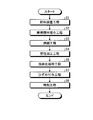
- FIG. 1 is a flowchart of a joint processing method according to the first embodiment.
- FIG. 2 is a cross-sectional view showing an example of a friction stir welding apparatus used in the friction stir welding process.
- FIG. 3 is a graph relating to a joint where the Vickers hardness is changed by the annealing process.
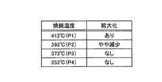
- FIG. 4 is a table relating to crystal grains that change at the joint due to the annealing process.
- FIG. 5 is a view showing an example of a joint portion corresponding to the table of FIG.
- FIG. 6 is a graph of the grain size which changes with the amount of strain given in the plastic working process.
- FIG. 7 is a view showing an example of a joint obtained by performing a plastic working process.
- FIG. 1 is a flowchart of a joint processing method according to the first embodiment.
- FIG. 2 is a cross-sectional view showing an example of a friction stir welding apparatus used in the friction stir welding process.
- FIG. 3 is a graph relating to
- FIG. 8 is a graph regarding the amount of strain (thickness change) of the dome member to which the joint processing method is applied.
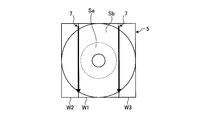
- FIG. 9 is a plan view showing an example of a flat plate which is a material of the dome member installed in the material installation process.
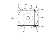
- FIG. 10 is a top view which shows an example of the flat plate used as the material of the dome member installed in a material installation process.
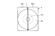
- FIG. 11 is a plan view showing a conventional example of a flat plate which is a material of the dome member.
- FIG. 12 is a flowchart of the joint processing method according to the second embodiment.
- FIG. 13 is an explanatory view of the method for processing a joint portion according to the third embodiment.
- a flat plate configured by using an aluminum alloy is applied as the metal material.
- the flat plate is installed such that the end faces of the flat plate are butted to form a groove (joint).
- the groove part which abuts the flat plate was made into the to-be-joined part used as the object of friction stir welding, it is not specifically limited by this structure, It may be.
- a joint is formed by performing friction stir welding (FSW) on the groove formed in the material installation process S1, and thereby, flat plates that are butted to each other are formed. Are joined.
- FSW friction stir welding
- the friction stir welding apparatus 1 is used, and friction stir welding is performed from both sides with the groove portion interposed therebetween.
- the friction stir welding apparatus 1 has a first rotary tool 21 and a second rotary tool 22 as welding tools.
- the first rotary tool 21 is disposed on the upper side (one side) in the thickness direction of the groove 6 with the groove 6 interposed therebetween.
- the first rotary tool 21 rotates about the first rotation axis I1 and is pressed against the upper surface of the groove 6.
- the second rotary tool 22 is disposed on the lower side (the other side) in the thickness direction of the groove 6 with the groove 6 interposed therebetween.
- the second rotation tool 22 rotates about the second rotation axis I 2 and is pressed against the lower surface of the groove 6.
- the first rotation tool 21 is configured to include a first probe 32 and a first shoulder portion 35.
- the first probe 32 is formed to be longer than half the thickness of the groove 6.
- channel for stirring the metal of the softened groove part 6 is formed in the outer peripheral surface of the 1st probe 32.
- the first shoulder 35 is in contact with the upper surface of the groove 6.
- the first rotary tool 21 as described above rotates the first shoulder portion 35 in contact with the upper surface of the groove portion 6 to impart heat by friction to the groove portion 6 to apply heat thereto.
- the groove portion 6 softened in the above is stirred by the first probe 32. Therefore, a first agitation area to be frictionally agitated by the first rotary tool 21 is formed on the upper side of the groove portion 6.
- the flat plate 5 including the joint portion formed in the friction stir welding step S2 is annealed (annealed) at a predetermined annealing temperature.
- the annealing step S3 is performed to make the hardness of the flat plate 5 after the friction stir welding uniform.
- the horizontal axis is the distance from the center (0) of the weld width of the joint
- the vertical axis is the Vickers hardness (Hv).
- Hv Vickers hardness
- the joint after annealing has substantially the same hardness over the entire area of the welding width, and the hardness is uniform.
- the annealing step S3 by making the hardness of the joint uniform, local deformation of the flat plate 5 in which the joint is formed is suppressed during plastic working in the plastic working step S4 which is a post-step. It is possible to apply strain uniformly.
- the change of the crystal grain diameter of the junction part 7 by the change of the annealing temperature in annealing process S3 is demonstrated.
- the crystal grain size of the aluminum alloy in the joint portion 7 changes in size depending on the annealing temperature in the annealing step S3.
- the term on the left side is the annealing temperature
- the term on the right side is the occurrence of coarsening in which the crystal grain size is increased.
- the joint portion 7 formed when the annealing temperature shown in FIG. 4 is 413 ° C. is P1 shown in FIG.
- the joint 7 formed at the annealing temperature of 393 ° C. shown in FIG. 4 is P2 shown in FIG.
- the joint part 7 formed when the annealing temperature shown in FIG. 4 is 373 ° C. is P3 shown in FIG.
- the junction part 7 formed when the annealing temperature shown in FIG. 4 is 353 ° C. is P4 shown in FIG.
- the friction stir temperature of the friction stir bonding step S2 is a temperature between 400 ° C. and 550 ° C.
- the annealing temperature at P1 is higher than the lower limit value of the friction stir temperature It has become.
- the annealing temperature at P2 is slightly lower than the friction stirring temperature.
- the annealing temperature at P3 is lower than the friction stirring temperature and lower than the annealing temperature of P2.
- the annealing temperature in P4 is lower than friction stirring temperature, and is lower than the annealing temperature of P3.
- the plastic working is performed in a cold state on the joint 7 after annealing under predetermined plastic working conditions.
- the plastic working conditions are conditions which become equal to or less than the grain size of the aluminum alloy in the groove 6 before the friction stir welding step S2.
- a predetermined amount of strain is given to the joint 7 by plastic working so that the thickness of the joint 7 is reduced.
- the flat plate 5 including the joint 7 after plastic working is solutionized.
- the grain size of the crystal formed in the joint 7 changes depending on the plastic working conditions in the plastic working step S4.
- the crystal grain diameter which changes according to the amount of strain given to junction part 7 after plastic working process S4 and solution treatment process S5 is explained.
- the horizontal axis is the strain amount
- the vertical axis is the crystal grain size.
- the amount of strain is the amount of deformation of the joint 7 before and after plastic working, for example, the ratio when the thickness of the joint 7 after plastic working is thinner than the thickness of the joint 7 before plastic working It is.
- the crystal grain sizes of the groove 6 and the base material before the friction stir welding are in the range of the region R.
- the crystal grain size in the region R is approximately between 0.1 mm and 0.15 mm.
- the grain size of the joint 7 is about 0.35 mm.
- the grain size of the joint 7 is about 0.15 mm.
- the plastic working process S4 by performing the plastic working on the joint 7 under the plastic working condition in which the strain amount is 5% or more, the coarsening of the crystal grains of the joint 7 can be suppressed. confirmed. For this reason, in the plastic working process S4, the plastic working is performed on the joint portion 7 under plastic working conditions in which the strain amount is 5% or more.
- the strain amount is 10% or more, the structure including the base material portion is miniaturized and becomes uniform, and the difference between the bonding portion 7 and the base material portion is not recognized.
- the dome member 51 is formed in the plastic working process S4 of the joint processing method. That is, the dome member 51 is formed by plastically working the flat plate 5 before plastic working. In the plastic working process S4, a dome-shaped dome member 51 that is curved outward from the center side of the flat plate 5 is formed by performing rotational plastic working, so-called spinning, on the flat plate 5.
- the horizontal axis is the position (radial position) in the radial direction of the dome member 51
- the vertical axis is the amount of strain.
- the amount of strain is the ratio of the thickness after plastic working to the thickness before plastic working, and the numerical value when the thickness before and after plastic working does not change is 1.00, and the strain is 0%. It becomes.
- the amount of strain of the dome member 51 subjected to rotational plastic working increases from the center side toward the outer side, and the strain amount becomes 5% at a position where the radial position is r1.
- FIGS. 9 and 10 show the flat plate 5 before plastic working to be friction stir welded.
- a region corresponding to the region Sa of the dome member 51 is formed on the center side, and a region corresponding to the region Sb of the dome member 51 is formed outside the region Sa. ing.
- the bonding portion 7 formed in the flat plate 5 is formed in the region Sb.
- the flat plate 5 when forming the joint portion 7 in the region Sb, the flat plate 5 is configured using three work pieces W1 to W3. Specifically, among the three work pieces W1 to W3, the work piece W1 has a size in which the area Sa can be accommodated, and the work piece W1 is disposed at the center. The remaining two work pieces W2 and W3 are disposed on both sides of the work piece W1, whereby groove portions 6 are respectively formed on both sides of the work piece W1. In the friction stir welding step S2, by friction stir welding the two groove portions 6 formed on both sides of the work piece W1, the flat plate 5 in which the bonding portion 7 is formed in the region Sb can be obtained.
- the flat plate 5 is configured using five work pieces W11 to W15. Specifically, among the five work pieces W11 to W15, the work piece W11 has a size that the area Sa can be accommodated, and the work piece W11 is disposed at the center. The remaining four work pieces W12 to W15 are arranged around the work piece W11, whereby the groove 6 is formed around the work piece W11. In the friction stir welding step S2, by friction stir welding the four groove portions 6 formed around the work piece W11, the flat plate 5 in which the bonding portion 7 is formed in the region Sb can be obtained.
- the joining start point and joining end point in the friction stir welding step S2 are at the time of spinning It can be located in the area outside the dome member 51 to be formed. For this reason, it is possible to make one side of the rectangular flat plate 5 substantially the same length as the diameter of the dome member 51.
- the nuclei of recrystallization are increased in the joint portion 7 It can be done.
- the solution treatment step S5 is performed after the plastic working step S4
- the growth of the nuclei of recrystallization can be mutually suppressed by an amount corresponding to the increase of the nuclei of recrystallization.
- the crystal grains of the bonding portion 7 can be made finer.
- the coarsening of the crystal grains of the joint 7 is suitably made by setting the plastic working condition to be a condition where the strain amount of the joint before and after the plastic working process S4 is 5% or more. It can be suppressed.
- the hardness of the joint portion 7 of the flat plate 5 can be made uniform, and local deformation of the flat plate 5 can be achieved during the plastic working step S4. While being suppressed, strain can be applied uniformly.
- Example 1 coarsening of the crystal grain in the junction part 7 can be suppressed by making friction stirring temperature high in annealing process S3, and lowering annealing temperature.
- the friction stir welding is performed from both sides of the groove portion 6 and the first stirring region formed by the first rotary tool 21 and the second stirring formed by the second rotary tool 22 It is possible to overlap the area. For this reason, since it can carry out friction stirring over the whole region of the thickness direction of the junction part 7, the heat input to the junction part 7 by friction stirring can be performed over the whole region of the thickness direction.
- the hardness of the flat plate 5 can be increased by performing the aging step S6 after performing the plastic working step S4 in a cold state and performing the solution treatment step S5. Therefore, even when the joint 7 is formed on the flat plate 5, it can be T6 which is the quality of the aluminum alloy defined by the Japanese Industrial Standard (JIS).
- JIS Japanese Industrial Standard
- the flat plate 5 can be formed on the dome member 51 while giving distortion to the flat plate 5, so coarsening of crystal grains is caused.
- the flat plate 5 can be processed into a dome shape while suppressing the
- the plastic working process S4 can be performed in a cold state, the plastic working to the joint 7 is appropriately performed while appropriately controlling the amount of strain given to the joint 7. be able to. Further, when the temperature is 100 ° C. or less, no recovery phenomenon etc. occurs, so that no phenomenon occurs in which the strain inserted by plastic working is released during processing, and the amount of nuclei of recrystallization for suppressing coarsening Can also be controlled.
- Example 1 although annealing process S3 was provided, when hardness of joining part 7 after friction stir welding process S2 becomes uniform, or a difference in hardness does not have an adverse effect on plastic working process S4.
- the annealing step S3 may be omitted.
- FIG. 12 is a flowchart of the joint processing method according to the second embodiment.
- the portions different from the first embodiment will be described, and the portions having the same configuration as the first embodiment are denoted by the same reference numerals.
- the strain applying step S7 is performed after the solution processing between the solution treatment step S5 and the aging step S6 of the joint processing method according to the first embodiment.
- the joint processing method according to the second embodiment will be described.
- the strain applying step S7 is performed after the solution treatment step S5 and before the aging step S6.
- the strength of the flat plate 5 is improved by plastically working the flat plate 5 after the solution treatment in a cold state.
- the amount of strain given to the flat plate 5 in the strain applying step S7 is in the range of 2% to 8%, and the larger the amount of strain, the higher the strength after the aging treatment.
- Example 2 after the plastic working process S4 is performed in the cold state and the solution treatment process S5 is performed, the strain applying process S7 is performed in the cold state, and the aging process S6 is performed.
- the strength of the flat plate 5 can be increased. Therefore, even when the joint portion 7 is formed on the flat plate 5, it can be T8 which is the quality of the aluminum alloy defined by the Japanese Industrial Standard (JIS). This is because the bonding portion 7 after the solution treatment has a crystal grain which is not coarsened, and therefore has a quality that can withstand processing even when a high degree of strain is applied.
- JIS Japanese Industrial Standard
- FIG. 13 is an explanatory view of the method for processing a joint portion according to the third embodiment.
- parts different from the first and second embodiments will be described to avoid redundant description, and the same reference numerals are given to parts having the same configuration as the first and second embodiments.
- the thickness of the joint 7 is larger than the thickness of the portion other than the joint. The joint processing method according to the third embodiment will be described below.
- Friction stir welding is performed by the rotary tool 21 and the second rotary tool 22 to form the joint 7 (S102).
- the thickness of the bonding portion 7 formed in the friction stir welding step S2 is larger than the thickness other than the bonding portion 7.
- plastic working is performed so that the thickness of the bonding portion 7 is reduced in the plastic working process S4, thereby suppressing the coarsening of crystal grains in the bonding portion 7;
- the thickness of the bonding portion 7 and the thickness of the portion other than the bonding portion 7 can be made the same thickness.
- the forging process may be performed as the plastic working process S4.
- the dead metal region is not formed by applying pressure to the joint portion 7 a plurality of times with a hammer or the like. And plastic working may be performed.
Landscapes
- Engineering & Computer Science (AREA)
- Mechanical Engineering (AREA)
- Chemical & Material Sciences (AREA)
- General Engineering & Computer Science (AREA)
- Physics & Mathematics (AREA)
- Thermal Sciences (AREA)
- Crystallography & Structural Chemistry (AREA)
- Materials Engineering (AREA)
- Metallurgy (AREA)
- Organic Chemistry (AREA)
- Pressure Welding/Diffusion-Bonding (AREA)
Priority Applications (2)
| Application Number | Priority Date | Filing Date | Title |
|---|---|---|---|
| US15/328,662 US10512985B2 (en) | 2014-09-24 | 2015-09-01 | Joint processing method and dome member |
| EP15845443.9A EP3159091B1 (en) | 2014-09-24 | 2015-09-01 | Joint processing method and dome member |
Applications Claiming Priority (2)
| Application Number | Priority Date | Filing Date | Title |
|---|---|---|---|
| JP2014194396A JP6403515B2 (ja) | 2014-09-24 | 2014-09-24 | 接合部処理方法及びドーム部材 |
| JP2014-194396 | 2014-09-24 |
Publications (1)
| Publication Number | Publication Date |
|---|---|
| WO2016047394A1 true WO2016047394A1 (ja) | 2016-03-31 |
Family
ID=55580922
Family Applications (1)
| Application Number | Title | Priority Date | Filing Date |
|---|---|---|---|
| PCT/JP2015/074846 Ceased WO2016047394A1 (ja) | 2014-09-24 | 2015-09-01 | 接合部処理方法及びドーム部材 |
Country Status (4)
| Country | Link |
|---|---|
| US (1) | US10512985B2 (https=) |
| EP (1) | EP3159091B1 (https=) |
| JP (1) | JP6403515B2 (https=) |
| WO (1) | WO2016047394A1 (https=) |
Families Citing this family (8)
| Publication number | Priority date | Publication date | Assignee | Title |
|---|---|---|---|---|
| JP6332562B2 (ja) * | 2016-03-31 | 2018-05-30 | Jfeスチール株式会社 | 構造用鋼の摩擦撹拌接合方法及び装置 |
| WO2019026864A1 (ja) | 2017-08-01 | 2019-02-07 | Jfeスチール株式会社 | 金属板の両面摩擦撹拌接合方法および両面摩擦撹拌接合装置 |
| EP3653329B1 (en) * | 2017-09-13 | 2023-10-11 | JFE Steel Corporation | Double-sided friction stir welding method for metal plate |
| JP7118688B2 (ja) * | 2018-03-28 | 2022-08-16 | 三菱重工業株式会社 | 被加工物の加工方法及び加工装置 |
| WO2022010718A1 (en) * | 2020-07-09 | 2022-01-13 | Lam Research Corporation | Friction stir processing for corrosion resistance |
| JP7452496B2 (ja) * | 2021-06-07 | 2024-03-19 | 日本軽金属株式会社 | 接合体の製造方法および接合装置 |
| CN115572981B (zh) * | 2022-09-09 | 2024-06-11 | 常熟市常沪螺母制造有限公司 | 金属冷镦线材表面结晶工艺生产线 |
| CN119772514A (zh) * | 2024-12-17 | 2025-04-08 | 中国科学院金属研究所 | 一种铝合金件及其制备方法 |
Citations (8)
| Publication number | Priority date | Publication date | Assignee | Title |
|---|---|---|---|---|
| JPH1128582A (ja) * | 1997-07-07 | 1999-02-02 | Showa Alum Corp | 摩擦撹拌接合装置 |
| JP2002263865A (ja) * | 2001-03-07 | 2002-09-17 | Honda Motor Co Ltd | 摩擦撹拌接合法 |
| JP2003236635A (ja) * | 2002-02-15 | 2003-08-26 | Mitsubishi Heavy Ind Ltd | アルミ合金製圧力容器に使用するドームおよびその製造方法 |
| JP2007190606A (ja) * | 2006-01-19 | 2007-08-02 | Susumu Hioki | 加熱摩擦攪拌溶接方法および装置 |
| JP2008279509A (ja) * | 2008-07-14 | 2008-11-20 | Showa Denko Kk | 接合継手の製造方法 |
| JP2009018348A (ja) * | 2008-10-29 | 2009-01-29 | Nippon Light Metal Co Ltd | 厚肉被接合材の接合方法及び接合構造 |
| WO2014097631A1 (ja) * | 2012-12-21 | 2014-06-26 | 川崎重工業株式会社 | アルミニウム合金製航空機用成形部品の製造方法および航空機用成形部品 |
| JP2014155963A (ja) * | 2008-03-11 | 2014-08-28 | Nippon Light Metal Co Ltd | 接合方法 |
Family Cites Families (31)
| Publication number | Priority date | Publication date | Assignee | Title |
|---|---|---|---|---|
| US3024938A (en) * | 1959-07-27 | 1962-03-13 | Budd Co | Sectional pressure vessel and method of making it |
| JPS4838388B1 (https=) * | 1969-03-28 | 1973-11-16 | ||
| US5098490A (en) * | 1990-10-05 | 1992-03-24 | Shin Huu | Super position aluminum alloy can stock manufacturing process |
| GB9125978D0 (en) * | 1991-12-06 | 1992-02-05 | Welding Inst | Hot shear butt welding |
| US5152452A (en) * | 1992-03-10 | 1992-10-06 | York Industries, Inc. | Pressure vessel and method |
| US5697511A (en) * | 1996-09-27 | 1997-12-16 | Boeing North American, Inc. | Tank and method of fabrication |
| US6258463B1 (en) * | 2000-03-02 | 2001-07-10 | Praxair S.T. Technology, Inc. | Anodized cryogenically treated aluminum |
| EP2080579A1 (en) * | 2001-03-07 | 2009-07-22 | Showa Denko K.K. | Friction agitation joining method, method for manufacturing joined butted members, and friction agitation joining apparatus |
| US6660106B1 (en) | 2001-08-22 | 2003-12-09 | The Boeing Company | Methods of manufacture of spin-forming blanks, particularly for fabrication of rocket domes |
| KR101067033B1 (ko) * | 2003-04-25 | 2011-09-22 | 혼다 기켄 고교 가부시키가이샤 | 튜브형 금속 본체 및 그 제조 방법 그리고 압력 용기를위한 라이너 및 그 제조 방법 |
| FR2855083B1 (fr) * | 2003-05-20 | 2006-05-26 | Pechiney Rhenalu | Procede de fabrication de pieces en alliage d'aluminium soudees par friction |
| JP4436148B2 (ja) * | 2004-02-09 | 2010-03-24 | 本田技研工業株式会社 | 圧力容器用ライナおよびその製造方法 |
| US20080274383A1 (en) * | 2004-04-08 | 2008-11-06 | Showa Denko K.K. | Process for Fabricating Pressure Vessel Liner |
| US7971740B2 (en) * | 2004-07-06 | 2011-07-05 | Honda Motor Co., Ltd. | Pressure vessel |
| WO2007111325A1 (ja) * | 2006-03-28 | 2007-10-04 | Showa Denko K.K. | ライナ構成部材の製造方法 |
| US20080277036A1 (en) | 2007-05-11 | 2008-11-13 | Luxfer Group Limited | Method for manufacturing tanks |
| US8079126B2 (en) * | 2008-01-25 | 2011-12-20 | Pratt & Whitney Rocketdyne, Inc. | Friction stir welded bladder fuel tank |
| FR2945464B1 (fr) * | 2009-05-13 | 2012-03-23 | Alcan Rhenalu | Procede d'assemblage par soudage de pieces en alliage d'aluminium. |
| JP5074456B2 (ja) * | 2009-06-03 | 2012-11-14 | 本田技研工業株式会社 | 車両用強度部材 |
| US8728389B2 (en) * | 2009-09-01 | 2014-05-20 | United Technologies Corporation | Fabrication of L12 aluminum alloy tanks and other vessels by roll forming, spin forming, and friction stir welding |
| JP4838388B2 (ja) * | 2009-11-18 | 2011-12-14 | 三菱日立製鉄機械株式会社 | 両面摩擦攪拌接合方法および装置並びに両面摩擦攪拌接合用ツールセット |
| US20120031249A1 (en) * | 2010-08-06 | 2012-02-09 | Osaka Municipal Technical Research Institute | Method for refining texture of ferrous material, and ferrous material and blade having microscopic texture |
| WO2012029176A1 (ja) * | 2010-09-03 | 2012-03-08 | 三菱日立製鉄機械株式会社 | 摩擦攪拌接合システムおよび摩擦攪拌接合方法 |
| US9090950B2 (en) | 2010-10-13 | 2015-07-28 | The United States Of America As Represented By The Administrator Of The National Aeronautics And Space Administration | Abnormal grain growth suppression in aluminum alloys |
| JP2014040621A (ja) * | 2012-08-21 | 2014-03-06 | Mitsubishi Heavy Ind Ltd | 鏡板の製造方法 |
| JP6155155B2 (ja) * | 2013-09-27 | 2017-06-28 | 三菱重工業株式会社 | 摩擦撹拌工具、摩擦撹拌接合装置及び摩擦撹拌接合方法 |
| WO2015069376A1 (en) * | 2013-11-08 | 2015-05-14 | United Technologies Corporation | High conformal pressure vessel |
| JP6284444B2 (ja) * | 2014-06-25 | 2018-02-28 | 三菱重工業株式会社 | 摩擦撹拌接合方法及び摩擦撹拌接合装置 |
| BR112017007186B1 (pt) * | 2014-10-07 | 2022-03-03 | United Technologies Corporation | Conjunto de recipiente de pressão, e, método para formação de um conjunto de recipiente de pressão |
| EP3204683B1 (en) * | 2014-10-07 | 2020-09-02 | United Technologies Corporation | Pressure vessel fluid manifold assembly |
| KR102098217B1 (ko) * | 2016-03-31 | 2020-04-07 | 제이에프이 스틸 가부시키가이샤 | 구조용 강의 마찰 교반 접합 방법 및 장치 |
-
2014
- 2014-09-24 JP JP2014194396A patent/JP6403515B2/ja active Active
-
2015
- 2015-09-01 WO PCT/JP2015/074846 patent/WO2016047394A1/ja not_active Ceased
- 2015-09-01 US US15/328,662 patent/US10512985B2/en active Active
- 2015-09-01 EP EP15845443.9A patent/EP3159091B1/en active Active
Patent Citations (8)
| Publication number | Priority date | Publication date | Assignee | Title |
|---|---|---|---|---|
| JPH1128582A (ja) * | 1997-07-07 | 1999-02-02 | Showa Alum Corp | 摩擦撹拌接合装置 |
| JP2002263865A (ja) * | 2001-03-07 | 2002-09-17 | Honda Motor Co Ltd | 摩擦撹拌接合法 |
| JP2003236635A (ja) * | 2002-02-15 | 2003-08-26 | Mitsubishi Heavy Ind Ltd | アルミ合金製圧力容器に使用するドームおよびその製造方法 |
| JP2007190606A (ja) * | 2006-01-19 | 2007-08-02 | Susumu Hioki | 加熱摩擦攪拌溶接方法および装置 |
| JP2014155963A (ja) * | 2008-03-11 | 2014-08-28 | Nippon Light Metal Co Ltd | 接合方法 |
| JP2008279509A (ja) * | 2008-07-14 | 2008-11-20 | Showa Denko Kk | 接合継手の製造方法 |
| JP2009018348A (ja) * | 2008-10-29 | 2009-01-29 | Nippon Light Metal Co Ltd | 厚肉被接合材の接合方法及び接合構造 |
| WO2014097631A1 (ja) * | 2012-12-21 | 2014-06-26 | 川崎重工業株式会社 | アルミニウム合金製航空機用成形部品の製造方法および航空機用成形部品 |
Non-Patent Citations (1)
| Title |
|---|
| See also references of EP3159091A1 * |
Also Published As
| Publication number | Publication date |
|---|---|
| EP3159091B1 (en) | 2020-07-29 |
| US10512985B2 (en) | 2019-12-24 |
| JP2016064426A (ja) | 2016-04-28 |
| EP3159091A1 (en) | 2017-04-26 |
| US20170209957A1 (en) | 2017-07-27 |
| EP3159091A4 (en) | 2017-08-23 |
| JP6403515B2 (ja) | 2018-10-10 |
Similar Documents
| Publication | Publication Date | Title |
|---|---|---|
| WO2016047394A1 (ja) | 接合部処理方法及びドーム部材 | |
| JP6515376B2 (ja) | 均質化鍛造品を製造する構築成形方法 | |
| RU2699342C1 (ru) | Способ точечной контактной сварки | |
| WO2021060176A1 (ja) | 両面摩擦攪拌接合方法、冷延鋼帯及びめっき鋼帯の製造方法、両面摩擦攪拌接合装置、並びに冷延鋼帯及びめっき鋼帯の製造設備 | |
| US10022816B2 (en) | Friction welding method | |
| US10472698B2 (en) | Method of production of brazed joint and such a brazed joint | |
| WO2013008314A1 (ja) | リチウムイオン電池ケース用アルミニウム合金板材 | |
| CN109477171B (zh) | 局部快速退火的铝合金坯件 | |
| CN1990156A (zh) | 用来激光焊接热轧钢板的方法及其设备 | |
| JP2011140708A (ja) | リチウムイオン電池ケース用アルミニウム合金板材 | |
| CN111989421A (zh) | 溅射靶材及其制造方法 | |
| Choudhary et al. | Effect of welding parameters on microstructure and mechanical properties of friction stir welded Al 6061 aluminum alloy joints | |
| JP2016064426A5 (https=) | ||
| CN108883458A (zh) | 机械嵌接接合部件及其制造方法 | |
| JP2016032834A (ja) | 重ね溶接部材、重ね溶接部材の重ね抵抗シーム溶接方法及び重ね溶接部を備える自動車用重ね溶接部材 | |
| KR20140069875A (ko) | 고강도-고연성 층상복합알루미늄합금판재 | |
| KR102299907B1 (ko) | 내부 가열 방식의 단조 장치 및 내부 가열 방식의 단조 장치를 이용한 Ti-Al 합금 빌렛 제조 방법 | |
| JP4351025B2 (ja) | 熱処理型アルミニウム合金材の接合方法 | |
| JP5033423B2 (ja) | 圧入接合における熱処理方法 | |
| CN110125522B (zh) | 一种近α相钛合金固态焊接焊缝组织等轴化处理方法 | |
| JP4351024B2 (ja) | 熱処理型アルミニウム合金材の摩擦攪拌接合方法 | |
| KR102299910B1 (ko) | 외주 가열 방식의 단조 장치 및 외주 가열 방식의 단조 장치를 이용한 Ti-Al 합금 빌렛 제조 방법 | |
| JP6060603B2 (ja) | フランジ加工性に優れた高強度缶用鋼板およびその製造方法 | |
| WO2019093399A1 (ja) | 高靭性を有する鋼材及びその製造方法、この鋼材を用いた構造用鋼板 | |
| RU2709908C1 (ru) | Способ получения сварных соединений термоупрочняемых алюминиевых сплавов с высоким пределом выносливости |
Legal Events
| Date | Code | Title | Description |
|---|---|---|---|
| 121 | Ep: the epo has been informed by wipo that ep was designated in this application |
Ref document number: 15845443 Country of ref document: EP Kind code of ref document: A1 |
|
| REEP | Request for entry into the european phase |
Ref document number: 2015845443 Country of ref document: EP |
|
| WWE | Wipo information: entry into national phase |
Ref document number: 2015845443 Country of ref document: EP |
|
| WWE | Wipo information: entry into national phase |
Ref document number: 15328662 Country of ref document: US |
|
| NENP | Non-entry into the national phase |
Ref country code: DE |