EP3157405B1 - Trapezförmiger wischbezug - Google Patents
Trapezförmiger wischbezug Download PDFInfo
- Publication number
- EP3157405B1 EP3157405B1 EP15726948.1A EP15726948A EP3157405B1 EP 3157405 B1 EP3157405 B1 EP 3157405B1 EP 15726948 A EP15726948 A EP 15726948A EP 3157405 B1 EP3157405 B1 EP 3157405B1
- Authority
- EP
- European Patent Office
- Prior art keywords
- mop cover
- stiffening element
- main body
- external edge
- Prior art date
- Legal status (The legal status is an assumption and is not a legal conclusion. Google has not performed a legal analysis and makes no representation as to the accuracy of the status listed.)
- Active
Links
- 239000000463 material Substances 0.000 claims description 2
- 230000003014 reinforcing effect Effects 0.000 claims description 2
- 229920002994 synthetic fiber Polymers 0.000 claims 1
- 238000004140 cleaning Methods 0.000 description 5
- 238000003780 insertion Methods 0.000 description 3
- 230000037431 insertion Effects 0.000 description 3
- 238000005520 cutting process Methods 0.000 description 1
- 238000004519 manufacturing process Methods 0.000 description 1
- 238000004080 punching Methods 0.000 description 1
- 238000003860 storage Methods 0.000 description 1
- 230000008093 supporting effect Effects 0.000 description 1
Images



Classifications
-
- A—HUMAN NECESSITIES
- A47—FURNITURE; DOMESTIC ARTICLES OR APPLIANCES; COFFEE MILLS; SPICE MILLS; SUCTION CLEANERS IN GENERAL
- A47L—DOMESTIC WASHING OR CLEANING; SUCTION CLEANERS IN GENERAL
- A47L13/00—Implements for cleaning floors, carpets, furniture, walls, or wall coverings
- A47L13/10—Scrubbing; Scouring; Cleaning; Polishing
- A47L13/42—Details
- A47L13/44—Securing scouring-cloths to the brush or like body of the implement
-
- A—HUMAN NECESSITIES
- A47—FURNITURE; DOMESTIC ARTICLES OR APPLIANCES; COFFEE MILLS; SPICE MILLS; SUCTION CLEANERS IN GENERAL
- A47L—DOMESTIC WASHING OR CLEANING; SUCTION CLEANERS IN GENERAL
- A47L13/00—Implements for cleaning floors, carpets, furniture, walls, or wall coverings
- A47L13/10—Scrubbing; Scouring; Cleaning; Polishing
- A47L13/16—Cloths; Pads; Sponges
-
- A—HUMAN NECESSITIES
- A47—FURNITURE; DOMESTIC ARTICLES OR APPLIANCES; COFFEE MILLS; SPICE MILLS; SUCTION CLEANERS IN GENERAL
- A47L—DOMESTIC WASHING OR CLEANING; SUCTION CLEANERS IN GENERAL
- A47L13/00—Implements for cleaning floors, carpets, furniture, walls, or wall coverings
- A47L13/10—Scrubbing; Scouring; Cleaning; Polishing
- A47L13/20—Mops
- A47L13/24—Frames for mops; Mop heads
- A47L13/254—Plate frames
- A47L13/256—Plate frames for mops made of cloth
-
- A—HUMAN NECESSITIES
- A47—FURNITURE; DOMESTIC ARTICLES OR APPLIANCES; COFFEE MILLS; SPICE MILLS; SUCTION CLEANERS IN GENERAL
- A47L—DOMESTIC WASHING OR CLEANING; SUCTION CLEANERS IN GENERAL
- A47L13/00—Implements for cleaning floors, carpets, furniture, walls, or wall coverings
- A47L13/10—Scrubbing; Scouring; Cleaning; Polishing
- A47L13/20—Mops
- A47L13/24—Frames for mops; Mop heads
- A47L13/254—Plate frames
- A47L13/258—Plate frames of adjustable or foldable type
Definitions
- the invention relates to a mop cover according to the preamble of patent claim 1.
- Wiper devices are known from the prior art, which have hinged wings. These wings are inserted in pockets of mop covers and oriented in parallel so that the mop covers are clamped.
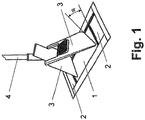
- Fig. 1 shows such a wiper device.
- Fig. 1 It can be seen that the insertion and clamping of the wings can be problematic, since the wings ultimately sit on a point on the ground. The wings are slightly tilted around this tip when the wings are subjected to a force directed to the ground.
- the DE 94 11 092 U1 describes a mop cover according to the preamble of independent claim 1.
- the invention is therefore the object of a mop cover of the type mentioned in such a design and further that it can be easily grasped with rectangular wings and clamped, the mop cover with as many degrees of freedom in corner areas is effectively feasible for cleaning.
- At least one outer edge and / or at least one pocket must be associated with at least one stiffening element for reinforced reinforcing of the base body, so that it is sufficiently stable if the pocket is not completely filled.
- the stiffening element takes over the filling and supporting effect of a wing, even if it does not fully fill the bag.
- the mop cover can be easily gripped and clamped with rectangular wings, wherein the mop cover with as many degrees of freedom in corners is effectively feasible for cleaning.
- a stiffening element could stabilize the base body in a region adjacent to a pocket in such a way that the base body retains its geometric shape in this area in a self-supporting manner, even if a wing with a rectangular free end or no wing with a trapezoidal free end is accommodated in the pocket , By this configuration, instead of wings and straps or wires can be inserted into the pockets without the usability of the mop cover is significantly affected.
- a stiffening element could be made or molded from a plastic plate or from a plastic plate. Such a stiffening element is inexpensive and easy, for example by punching or cutting, produced.
- a stiffening element could completely overlap a pocket.
- the mop cover is particularly strong stabilized.
- a stiffening element could partially overlap a pocket. This can save material for the stiffening element.
- a stiffening element could be strip-shaped, run on a longer outer edge and extend into a corner region of the longer outer edge, in which a shorter outer edge opens. Due to the strip shape, very little plastic or plastic is required for the stiffening element.
- a wiper device could comprise a mop cover of the type described here and two wings which can be pivoted relative to each other, each having a rectangular free end. Such a wiper device can easily be used with a trapezoidal mop cover. As a result, cleaning of corner areas is greatly simplified.
- Fig. 1 shows a rectangular mop cover 1, in the pockets 2, two pivotable wings 3 of a wiper device 4 are introduced.
- the free ends of the wings 3 are trapezoidal and each lie with a point on the ground. This can lead to a tilting of the wings 3. As a result, the insertion of the wings 3 in the pockets 2 and the clamping is difficult.
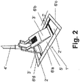
- Fig. 2 shows a mop cover 1 ', comprising a flat main body 5' with four outer edges 6'a, 6'b, 6'c, 6'd, wherein a first longer outer edge 6'a is parallel to a second longer outer edge 6'b oriented wherein the first longer outer edge 6'a is longer than the second longer outer edge 6'b, wherein two shorter outer edges 6'c, 6'd each extend between the longer outer edges 6'a, 6'b, and wherein the main body 5 'at least two pockets 2' are assigned, in which wings 3 'or clamping elements of a wiper device 4' for mounting the planar base body 5 'can be inserted.
- the free ends of the wings 3 ' are rectangular and rest when inserted into the pockets 2' each on a line, namely on its edge facing the ground.
- the wings 3 'do not fill the trapezoidal pockets 2' completely off. Edge regions of the mop cover 1 'can then not be sufficiently stable to lead them with good cleaning performance in corners.
- the mop covers 1 “, 1"', 1 "” of the Fig. 3 to 5 Stiffening elements 7 ", 7"', 7 “” assigned.
- At least one outer edge 6 “a, 6" b, 6 “c, 6" d, 6 “'a, 6"' b, 6 “'c, 6"' d, 6 “" a, 6 "" b, 6 “” c, 6 “” d and / or at least one pocket 2 ", 2"', 2 "” is at least one stiffening element 7 “, 7"', 7 “” for partially reinforced stiffening of the main body 5 ", 5"' , 5 "” assigned.
- a stiffening element 7 “, 7" ', 7 “” stabilizes the main body 5 “, 5"', 5 “” in a region adjacent to a pocket 2 ", 2” ', 2 “” in such a way that the main body 5 “, 5 “', 5" “in this area retains its geometric shape self-supporting, even if in the pocket 2", 2 "', 2” "a wing 3 'with rectangular free end or no wing with trapezoidal free end is added.
- the stiffening element 7 ", 7" ', 7 "" is made of a plastic plate or a plastic plate or molded.
- Fig. 3 shows that a stiffening element 7 "one pocket 2" completely overlaps. Both pockets 2 "are completely overlapped.
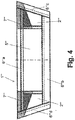
- Fig. 4 shows that a stiffening element 7 "'partially overlaps a pocket 2"'. Both pockets 2 "'are partially overlapped.
- Fig. 5 shows that a stiffening element 7 "" is strip-shaped, extends at a longer outer edge 6 "" a and extends into a corner region of the longer outer edge 6 "" a, in which a shorter outer edge 6 "" c or 6 "" d empties.
- Fig. 3 to 5 are two stiffening elements 7 ", 7"', 7 “” with respect to a symmetry axis mirrored opposite.
- Fig. 6 shows a wiper device 4 ', which comprises a rectangular mop cover 1 and two relatively pivotable wings 3', each with a rectangular free end.
- a wiper device 4 ' has almost no pivoting degrees of freedom in corner areas.
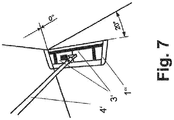
- a wiper device 4 ' which comprises a trapezoidal mop cover 1 "and two wings 3' which are pivotable relative to each other, each having a rectangular free end Held corner and swung around this tip.
- the swivel angle here is 20 °.
Landscapes
- Cleaning Implements For Floors, Carpets, Furniture, Walls, And The Like (AREA)
Description
- Die Erfindung betrifft einen Wischbezug gemäß dem Oberbegriff des Patentanspruchs 1.
- Aus dem Stand der Technik sind Wischgeräte bekannt, die aufklappbare Flügel aufweisen. Diese Flügel werden in Taschen von Wischbezügen eingeführt und derart parallel orientiert, dass die Wischbezüge aufgespannt werden.
- Insbesondere sind aus dem Stand der Technik Wischgeräte bekannt, deren Flügel freie trapezförmige Enden aufweisen.
Fig. 1 zeigt ein solches Wischgerät. AusFig. 1 ist ersichtlich, dass das Einführen und Aufspannen der Flügel problematisch sein kann, da die Flügel letztlich auf einer Spitze auf dem Boden aufsitzen. Die Flügel sind um diese Spitze leicht verkippbar, wenn auf die Flügel eine zum Boden gerichtete Kraft ausgeübt wird. - Die
DE 94 11 092 U1 beschreibt einen Wischbezug nach dem Oberbegriff des unabhängigen Anspruchs 1. - Weitaus leichter ist das Einführen und Aufspannen von Flügeln mit rechteckigen freien Enden, wie sie in
Fig. 2 dargestellt sind, da diese auf einer Linie auf dem Boden aufliegen. - Wenn allerdings solche rechteckigen Flügel in einen trapezförmigen Wischbezug eingeführt werden, können Bereiche der Taschen bzw. des Wischbezugs von den Flügeln unausgefüllt bleiben und daher instabil und für manche Reinigungszwecke nicht ausreichend gebrauchstauglich sein.
- Der Erfindung liegt daher die Aufgabe zugrunde, einen Wischbezug der eingangs genannten Art derart auszugestalten und weiterzubilden, dass dieser problemlos mit rechteckigen Flügeln ergreifbar und aufspannbar ist, wobei der Wischbezug mit möglichst vielen Freiheitsgraden in Eckbereichen effektiv zur Reinigung führbar ist.
- Die vorliegende Erfindung löst die zuvor genannte Aufgabe durch die Merkmale des Patentanspruchs 1.
- Erfindungsgemäß ist erkannt worden, dass mindestens einer Außenkante und/ oder mindestens einer Tasche mindestens ein Versteifungselement zur bereichsweise verstärkten Aussteifung des Grundkörpers zugeordnet sein muss, damit diese ausreichend stabil ist, wenn die Tasche nicht voll ausgefüllt ist. Das Versteifungselement übernimmt die ausfüllende und stützende Wirkungsweise eines Flügels, auch wenn dieser die Tasche nicht voll ausfüllt. Hierdurch ist der Wischbezug problemlos mit rechteckigen Flügeln ergreifbar und aufspannbar, wobei der Wischbezug mit möglichst vielen Freiheitsgraden in Eckbereichen effektiv zur Reinigung führbar ist.
- Folglich ist die eingangs genannte Aufgabe gelöst.
- Vor diesem Hintergrund könnte ein Versteifungselement den Grundkörper derart in einem an eine Tasche angrenzenden Bereich stabilisieren, dass der Grundkörper in diesem Bereich seine geometrische Form selbsttragend beibehält, auch wenn in der Tasche ein Flügel mit rechteckförmigem freien Ende oder kein Flügel mit trapezförmigem freien Ende aufgenommen ist. Durch diese Ausgestaltung können anstelle von Flügeln auch Bügel oder Drähte in die Taschen eingeführt werden, ohne dass die Gebrauchstauglichkeit des Wischbezugs merklich beeinträchtigt wird.
- Ein Versteifungselement könnte aus einer Kunststoffplatte oder aus einer Plastikplatte gefertigt oder geformt sein. Ein solches Versteifungselement ist kostengünstig und einfach, beispielsweise durch Stanzen oder Schneiden, herstellbar.
- Ein Versteifungselement könnte eine Tasche vollständig überlappen. Hierdurch ist der Wischbezug besonders stark stabilisiert.
- Ein Versteifungselement könnte eine Tasche teilweise überlappen. So kann Material für das Versteifungselement gespart werden.
- Ein Versteifungselement könnte streifenförmig ausgebildet sein, an einer längeren Außenkante verlaufen und sich bis in einen Eckbereich der längeren Außenkante erstrecken, in welchen eine kürzere Außenkante mündet. Durch die Streifenform wird besonders wenig Kunststoff oder Plastik für das Versteifungselement benötigt.
- Es könnten sich zwei Versteifungselemente mit Bezug auf eine Symmetrieachse spiegelbildlich gegenüberliegen. So ist die Fertigung eines Wischbezugs besonders leicht durchführbar und die Lagerhaltung für die Versteifungselemente erleichtert.
- Ein Wischgerät könnte einen Wischbezug der hier beschriebenen Art und zwei relativ zueinander verschwenkbare Flügel mit jeweils rechteckförmigem freien Ende umfassen. Ein solches Wischgerät kann problemlos mit einem trapezförmigen Wischbezug verwendet werden. Hierdurch ist eine Reinigung von Eckbereichen stark vereinfacht.
- In der Zeichnung zeigen
- Fig. 1
- ein Wischgerät mit aufklappbaren Flügeln, wobei die freien Enden der Flügel trapezförmig ausgestaltet sind und in die Taschen eines rechteckförmigen Wischbezugs eingeführt werden,
- Fig. 2
- ein Wischgerät mit aufklappbaren Flügeln, wobei die freien Enden der Flügel rechteckförmig ausgestaltet sind und in die Taschen eines trapezförmigen Wischbezugs eingeführt werden,
- Fig. 3
- ein trapezförmiger Wischbezug, dessen Taschen jeweils ein trapezförmiges Versteifungselement zugeordnet ist, wobei die Taschen vollständig von den Versteifungselementen überdeckt sind,
- Fig. 4
- ein weiterer trapezförmiger Wischbezug, dessen Taschen jeweils ein Versteifungselement zugeordnet ist, welches die Taschen nur teilweise überdeckt,
- Fig. 5
- ein weiterer trapezförmiger Wischbezug, dessen erster längerer Außenkante zwei gegenüberliegende streifenförmige Versteifungselemente zugeordnet sind,
- Fig. 6
- eine Darstellung, in der gezeigt ist, dass ein aufgespannter rechteckiger Wischbezug in Eckbereichen nahezu nicht verschwenkbar ist, und
- Fig. 7
- eine Darstellung, in der gezeigt ist, dass ein aufgespannter trapezförmiger Wischbezug in Eckbereichen verschwenkbar ist.
-
Fig. 1 zeigt einen rechteckförmigen Wischbezug 1, in dessen Taschen 2 zwei verschwenkbare Flügel 3 eines Wischgeräts 4 eingeführt werden. Die freien Enden der Flügel 3 sind trapezförmig und liegen jeweils mit einem Punkt auf dem Boden auf. Hierdurch kann es zu einem Verkippen der Flügel 3 kommen. Hierdurch wird das Einführen der Flügel 3 in die Taschen 2 sowie das Aufspannen erschwert. -
Fig. 2 zeigt einen Wischbezug 1', umfassend einen flächigen Grundkörper 5' mit vier Außenkanten 6'a, 6'b, 6'c, 6'd, wobei eine erste längere Außenkante 6'a zu einer zweiten längeren Außenkante 6'b parallel orientiert ist, wobei die erste längere Außenkante 6'a länger als die zweite längere Außenkante 6'b ist, wobei zwei kürzere Außenkanten 6'c, 6'd sich jeweils zwischen den längeren Außenkanten 6'a, 6'b erstrecken und wobei dem Grundkörper 5' mindestens zwei Taschen 2' zugeordnet sind, in welche Flügel 3' oder Spannelemente eines Wischgeräts 4' zum Aufspannen des flächigen Grundkörpers 5' einführbar sind. - Die freien Enden der Flügel 3' sind rechteckförmig und ruhen beim Einführen in die Taschen 2' jeweils auf einer Linie, nämlich auf ihrer dem Boden zugewandten Kante. Die Flügel 3' füllen die trapezförmigen Taschen 2' nicht vollständig aus. Randbereiche des Wischbezugs 1' können dann nicht ausreichend stabil sein, um diese mit guter Reinigungsleistung in Ecken zu führen.
- Daher sind den Wischbezügen 1", 1"', 1"" der
Fig. 3 bis 5 Versteifungselemente 7", 7"', 7"" zugeordnet. Mindestens einer Außenkante 6"a, 6"b, 6"c, 6"d, 6"'a, 6"'b, 6"'c, 6"'d, 6""a, 6""b, 6""c, 6""d und/ oder mindestens einer Tasche 2", 2"', 2"" ist mindestens ein Versteifungselement 7", 7"', 7"" zur bereichsweise verstärkten Aussteifung des Grundkörpers 5", 5"', 5"" zugeordnet. - Ein Versteifungselement 7", 7"', 7"" stabilisiert den Grundkörper 5", 5"', 5"" derart in einem an eine Tasche 2", 2"', 2"" angrenzenden Bereich, dass der Grundkörper 5", 5"', 5"" in diesem Bereich seine geometrische Form selbsttragend beibehält, auch wenn in der Tasche 2", 2"', 2"" ein Flügel 3' mit rechteckförmigem freien Ende oder kein Flügel mit trapezförmigem freien Ende aufgenommen ist.
- Das Versteifungselement 7", 7"', 7"" ist aus einer Kunststoffplatte oder aus einer Plastikplatte gefertigt oder geformt.
-
Fig. 3 zeigt, dass ein Versteifungselement 7" je eine Tasche 2" vollständig überlappt. Beide Taschen 2" sind vollständig überlappt. -
Fig. 4 zeigt, dass ein Versteifungselement 7"' eine Tasche 2"' teilweise überlappt. Beide Taschen 2"' sind teilweise überlappt. -
Fig. 5 zeigt, dass ein Versteifungselement 7"" streifenförmig ausgebildet ist, an einer längeren Außenkante 6""a verläuft und sich bis in einen Eckbereich der längeren Außenkante 6""a erstreckt, in welchen eine kürzere Außenkante 6""c oder 6""d mündet. - In den
Fig. 3 bis 5 liegen sich zwei Versteifungselemente 7", 7"', 7"" mit Bezug auf eine Symmetrieachse spiegelbildlich gegenüber. -
Fig. 6 zeigt ein Wischgerät 4', welches einen rechteckförmigen Wischbezug 1 und zwei relativ zueinander verschwenkbare Flügel 3' mit jeweils rechteckförmigem freien Ende umfasst. Ein solches Wischgerät 4' zeigt in Eckbereichen nahezu keine Verschwenkfreiheitsgrade. -
Fig. 7 hingegen zeigt ein Wischgerät 4', welches einen trapezförmigen Wischbezug 1" und zwei relativ zueinander verschwenkbare Flügel 3' mit jeweils rechteckförmigem freien Ende umfasst. Ein solches Wischgerät 4' zeigt in Eckbereichen zumindest einen Verschwenkfreiheitsgrad. Der Wischbezug 1" kann mit einer Spitze in einer Ecke gehalten und um diese Spitze geschwenkt werden. Der Schwenkwinkel beträgt hier 20°.
Claims (8)
- Wischbezug (1", 1"', 1""), umfassend einen flächigen Grundkörper (5", 5"', 5"") mit vier Außenkanten (6"a, 6"b, 6"c, 6"d, 6"'a, 6"'b, 6"'c, 6"'d, 6""a, 6""b, 6""c, 6""d), wobei eine erste längere Außenkante (6"a, 6"'a, 6""a) zu einer zweiten längeren Außenkante (6"b, 6"'b, 6""b) parallel orientiert ist, wobei die erste längere Außenkante (6"a, 6"'a, 6""a) länger als die zweite längere Außenkante (6"b, 6"'b, 6""b) ist, wobei zwei kürzere Außenkanten (6"c, 6"'c, 6""c, 6"d, 6"'d, 6""d) sich jeweils zwischen den längeren Außenkanten (6"a, 6"b, 6"'a, 6"'b, 6""a, 6""b) erstrecken und wobei dem Grundkörper (5", 5"', 5"") mindestens zwei Taschen (2", 2"', 2"") zugeordnet sind, in welche Flügel (3') oder Spannelemente eines Wischgeräts (4') zum Aufspannen des flächigen Grundkörpers (5", 5"', 5"") einführbar sind,
dadurch gekennzeichnet, dass mindestens einer Außenkante (6"a, 6"b, 6"c, 6"d, 6"'a, 6"'b, 6"'c, 6"'d, 6""a, 6""b, 6""c, 6""d) und/ oder mindestens einer Tasche (2", 2"', 2"") mindestens ein Versteifungselement (7", 7"', 7"") zur bereichsweise verstärkten Aussteifung des Grundkörpers (5", 5"', 5"") zugeordnet ist. - Wischbezug nach Anspruch 1, dadurch gekennzeichnet, dass ein Versteifungselement (7", 7"', 7"") den Grundkörper (5", 5"', 5"") derart in einem an eine Tasche (2", 2"', 2"") angrenzenden Bereich stabilisiert, dass der Grundkörper (5", 5"', 5"") in diesem Bereich seine geometrische Form selbsttragend beibehält, auch wenn in der Tasche (2", 2"' 2"") ein Flügel (3') mit rechteckförmigem freien Ende oder kein Flügel mit trapezförmigem freien Ende aufgenommen ist.
- Wischbezug nach Anspruch 1 oder 2, dadurch gekennzeichnet, dass ein Versteifungselement (7", 7"', 7"") aus einer Kunststoffplatte oder aus einer Plastikplatte gefertigt oder geformt ist.
- Wischbezug nach einem der voranstehenden Ansprüche, dadurch gekennzeichnet, dass ein Versteifungselement (7") eine Tasche (2") vollständig überlappt.
- Wischbezug nach einem der voranstehenden Ansprüche, dadurch gekennzeichnet, dass ein Versteifungselement (7"') eine Tasche (2"') teilweise überlappt.
- Wischbezug nach einem der voranstehenden Ansprüche, dadurch gekennzeichnet, dass ein Versteifungselement (7"") streifenförmig ausgebildet ist, an einer längeren Außenkante (6""a) verläuft und sich bis in einen Eckbereich der längeren Außenkante (6""a) erstreckt, in welchen eine kürzere Außenkante (6""c, 6""d) mündet.
- Wischbezug nach einem der voranstehenden Ansprüche, dadurch gekennzeichnet, dass sich zwei Versteifungselemente (7", 7"', 7"") mit Bezug auf eine Symmetrieachse spiegelbildlich gegenüberliegen.
- Wischgerät (4'), umfassend einen Wischbezug (1", 1"', 1"") nach einem der voranstehenden Ansprüche und zwei relativ zueinander verschwenkbare Flügel (3') mit jeweils rechteckförmigem freien Ende.
Priority Applications (1)
| Application Number | Priority Date | Filing Date | Title |
|---|---|---|---|
| PL15726948T PL3157405T3 (pl) | 2014-06-23 | 2015-06-01 | Trapezowa nakładka do mopa |
Applications Claiming Priority (2)
| Application Number | Priority Date | Filing Date | Title |
|---|---|---|---|
| DE102014008954.1A DE102014008954B3 (de) | 2014-06-23 | 2014-06-23 | Wischbezug und Wischgerät |
| PCT/EP2015/062142 WO2015197314A1 (de) | 2014-06-23 | 2015-06-01 | Trapezförmiger wischbezug |
Publications (2)
| Publication Number | Publication Date |
|---|---|
| EP3157405A1 EP3157405A1 (de) | 2017-04-26 |
| EP3157405B1 true EP3157405B1 (de) | 2018-12-26 |
Family
ID=53284254
Family Applications (1)
| Application Number | Title | Priority Date | Filing Date |
|---|---|---|---|
| EP15726948.1A Active EP3157405B1 (de) | 2014-06-23 | 2015-06-01 | Trapezförmiger wischbezug |
Country Status (8)
| Country | Link |
|---|---|
| US (1) | US10398282B2 (de) |
| EP (1) | EP3157405B1 (de) |
| CN (1) | CN106455894B (de) |
| AU (1) | AU2015281202B2 (de) |
| CA (1) | CA2949727C (de) |
| DE (1) | DE102014008954B3 (de) |
| PL (1) | PL3157405T3 (de) |
| WO (1) | WO2015197314A1 (de) |
Families Citing this family (3)
| Publication number | Priority date | Publication date | Assignee | Title |
|---|---|---|---|---|
| GB201716811D0 (en) * | 2017-10-13 | 2017-11-29 | Scot Young Res Limited | Head for a cleaning device |
| DE102020108607B4 (de) | 2020-03-27 | 2022-11-03 | Carl Freudenberg Kg | Reinigungseinrichtung zur Feuchtreinigung |
| EP4223202B1 (de) * | 2022-02-03 | 2025-01-22 | VERMOP GmbH | Wischmop zur reinigung von flächen |
Family Cites Families (15)
| Publication number | Priority date | Publication date | Assignee | Title |
|---|---|---|---|---|
| US3761991A (en) * | 1971-03-30 | 1973-10-02 | T Moss | Scrubbing or buffing device |
| DE9308947U1 (de) * | 1993-06-16 | 1993-08-19 | Öko-Clean-Vertriebsgesellschaft mbH, 83101 Rohrdorf | Textilbespannung für Reinigungsgerät |
| DE9411092U1 (de) | 1994-07-05 | 1994-09-01 | Coronet-Werke Gmbh, 69483 Wald-Michelbach | Reinigungsgerät mit einem Wischbezug |
| ATE244534T1 (de) * | 1999-11-04 | 2003-07-15 | Otto Oehme | Bodenreinigungsgerät |
| EP1166706A1 (de) | 2000-05-25 | 2002-01-02 | Sanamundi Aktiengesellschaft | Wischbezug |
| EP1704808B1 (de) * | 2005-03-16 | 2007-12-19 | Carl Freudenberg KG | Wischbezug |
| EP2301406B1 (de) * | 2007-04-03 | 2017-08-02 | Diversey, Inc. | Moppplatte mit Befestigungsmitteln und -methode |
| JP5390989B2 (ja) | 2009-08-24 | 2014-01-15 | 菊夫 山田 | 清掃シート |
| DE202011101141U1 (de) | 2011-05-27 | 2012-08-30 | Vermop Salmon Gmbh | Handbetätigtes Reinigungsgerät sowie Wischbezug |
| CA2825239A1 (en) | 2011-01-26 | 2012-08-02 | Vermop Salmon Gmbh | Hand-operated cleaning device and mop cover |
| DE102011107319B4 (de) * | 2011-07-06 | 2014-05-15 | Carl Freudenberg Kg | Flachwischer und Trägerplatte dafür |
| DE102012012402A1 (de) * | 2012-06-25 | 2014-01-02 | Carl Freudenberg Kg | Flachwischbezug mit Reinigungslippe |
| PL2872022T3 (pl) * | 2012-07-16 | 2017-04-28 | Vermop Salmon Gmbh | Uchwyt dla nakładek mopów |
| US9386898B2 (en) * | 2013-04-19 | 2016-07-12 | Ets Paul Masquin (S.A.S.) | Washing combination for the cleaning of floors or other planar surfaces |
| CA2908632C (en) * | 2013-04-25 | 2018-06-19 | Carl Freudenberg Kg | Mop cover |
-
2014
- 2014-06-23 DE DE102014008954.1A patent/DE102014008954B3/de not_active Expired - Fee Related
-
2015
- 2015-06-01 CA CA2949727A patent/CA2949727C/en active Active
- 2015-06-01 WO PCT/EP2015/062142 patent/WO2015197314A1/de not_active Ceased
- 2015-06-01 US US15/317,422 patent/US10398282B2/en not_active Expired - Fee Related
- 2015-06-01 PL PL15726948T patent/PL3157405T3/pl unknown
- 2015-06-01 EP EP15726948.1A patent/EP3157405B1/de active Active
- 2015-06-01 AU AU2015281202A patent/AU2015281202B2/en not_active Ceased
- 2015-06-01 CN CN201580029353.7A patent/CN106455894B/zh not_active Expired - Fee Related
Non-Patent Citations (1)
| Title |
|---|
| None * |
Also Published As
| Publication number | Publication date |
|---|---|
| WO2015197314A1 (de) | 2015-12-30 |
| CN106455894B (zh) | 2019-08-13 |
| AU2015281202B2 (en) | 2018-02-22 |
| DE102014008954B3 (de) | 2015-09-10 |
| PL3157405T3 (pl) | 2019-06-28 |
| US10398282B2 (en) | 2019-09-03 |
| CA2949727C (en) | 2019-09-24 |
| CA2949727A1 (en) | 2015-12-30 |
| US20170119228A1 (en) | 2017-05-04 |
| EP3157405A1 (de) | 2017-04-26 |
| AU2015281202A1 (en) | 2017-02-02 |
| CN106455894A (zh) | 2017-02-22 |
Similar Documents
| Publication | Publication Date | Title |
|---|---|---|
| DE20207845U1 (de) | Präsentationsgestelle für Informationen oder zur visuellen Werbung an Verkaufsstätten | |
| DE102014008954B3 (de) | Wischbezug und Wischgerät | |
| DE102011009496A1 (de) | Vorrichtung zum Fixieren von länglichen Gegenständen | |
| EP0143299A2 (de) | Kanten- oder Eckbeschlag | |
| DE9411165U1 (de) | Spreizanker | |
| DE102012100103A1 (de) | Trägervorrichtung | |
| DE202012100042U1 (de) | Ein Gehäuse zur Aufnahme eines Tabletcomputers mit einer Stütze | |
| EP2914909B1 (de) | Befestiger eines dachmontageträgers und dachmontagesystem | |
| EP2850966B1 (de) | Kosmetikapplikator mit einem ziehharmonikaförmigen Applikatorkörper | |
| EP2511460A1 (de) | Faltverbindung für faltbare Behälter | |
| DE202014105081U1 (de) | Becherhalter | |
| EP2428974B1 (de) | Elektrischer Leistensicherungstrennschalter mit beweglichem Schalterdeckel | |
| DE202010010684U1 (de) | Spannrahmen | |
| DE102021134511A1 (de) | Bausatz für einen Rahmen und Profilverbinder | |
| DE102009005448A1 (de) | Sternförmiger Dekorationsgegenstand | |
| EP1930245A1 (de) | Faltverbindung für faltbaren Behälter | |
| DE102014106116B4 (de) | Klappdeckelverschluss für eine Tube | |
| EP2851892B1 (de) | Standsichere Informationssäule | |
| DE202018104686U1 (de) | Transportabler Modulkörper zum Darstellen von Medieninhalten | |
| DE102009058986A1 (de) | Wischmopp mit Spannhalter und zugeordneter Bedienungsstange | |
| WO2021170182A1 (de) | Schutzhülle für mobilgeräte | |
| DE2118829A1 (de) | Halterung für eine Anzeigetafel, Tischkarte od.dgl | |
| EP3222189B1 (de) | Moppbezug und mopphalter | |
| EP3530165A1 (de) | Korb für reinigungs- und pflegeprodukte | |
| DE202014101944U1 (de) | Schirmsystem |
Legal Events
| Date | Code | Title | Description |
|---|---|---|---|
| STAA | Information on the status of an ep patent application or granted ep patent |
Free format text: STATUS: THE INTERNATIONAL PUBLICATION HAS BEEN MADE |
|
| PUAI | Public reference made under article 153(3) epc to a published international application that has entered the european phase |
Free format text: ORIGINAL CODE: 0009012 |
|
| STAA | Information on the status of an ep patent application or granted ep patent |
Free format text: STATUS: REQUEST FOR EXAMINATION WAS MADE |
|
| 17P | Request for examination filed |
Effective date: 20161201 |
|
| AK | Designated contracting states |
Kind code of ref document: A1 Designated state(s): AL AT BE BG CH CY CZ DE DK EE ES FI FR GB GR HR HU IE IS IT LI LT LU LV MC MK MT NL NO PL PT RO RS SE SI SK SM TR |
|
| AX | Request for extension of the european patent |
Extension state: BA ME |
|
| DAV | Request for validation of the european patent (deleted) | ||
| DAX | Request for extension of the european patent (deleted) | ||
| GRAP | Despatch of communication of intention to grant a patent |
Free format text: ORIGINAL CODE: EPIDOSNIGR1 |
|
| STAA | Information on the status of an ep patent application or granted ep patent |
Free format text: STATUS: GRANT OF PATENT IS INTENDED |
|
| INTG | Intention to grant announced |
Effective date: 20180831 |
|
| GRAS | Grant fee paid |
Free format text: ORIGINAL CODE: EPIDOSNIGR3 |
|
| GRAA | (expected) grant |
Free format text: ORIGINAL CODE: 0009210 |
|
| STAA | Information on the status of an ep patent application or granted ep patent |
Free format text: STATUS: THE PATENT HAS BEEN GRANTED |
|
| AK | Designated contracting states |
Kind code of ref document: B1 Designated state(s): AL AT BE BG CH CY CZ DE DK EE ES FI FR GB GR HR HU IE IS IT LI LT LU LV MC MK MT NL NO PL PT RO RS SE SI SK SM TR |
|
| REG | Reference to a national code |
Ref country code: GB Ref legal event code: FG4D Free format text: NOT ENGLISH |
|
| REG | Reference to a national code |
Ref country code: CH Ref legal event code: EP |
|
| REG | Reference to a national code |
Ref country code: AT Ref legal event code: REF Ref document number: 1080268 Country of ref document: AT Kind code of ref document: T Effective date: 20190115 |
|
| REG | Reference to a national code |
Ref country code: DE Ref legal event code: R096 Ref document number: 502015007432 Country of ref document: DE |
|
| REG | Reference to a national code |
Ref country code: IE Ref legal event code: FG4D Free format text: LANGUAGE OF EP DOCUMENT: GERMAN |
|
| PG25 | Lapsed in a contracting state [announced via postgrant information from national office to epo] |
Ref country code: FI Free format text: LAPSE BECAUSE OF FAILURE TO SUBMIT A TRANSLATION OF THE DESCRIPTION OR TO PAY THE FEE WITHIN THE PRESCRIBED TIME-LIMIT Effective date: 20181226 Ref country code: HR Free format text: LAPSE BECAUSE OF FAILURE TO SUBMIT A TRANSLATION OF THE DESCRIPTION OR TO PAY THE FEE WITHIN THE PRESCRIBED TIME-LIMIT Effective date: 20181226 Ref country code: LT Free format text: LAPSE BECAUSE OF FAILURE TO SUBMIT A TRANSLATION OF THE DESCRIPTION OR TO PAY THE FEE WITHIN THE PRESCRIBED TIME-LIMIT Effective date: 20181226 Ref country code: NO Free format text: LAPSE BECAUSE OF FAILURE TO SUBMIT A TRANSLATION OF THE DESCRIPTION OR TO PAY THE FEE WITHIN THE PRESCRIBED TIME-LIMIT Effective date: 20190326 Ref country code: LV Free format text: LAPSE BECAUSE OF FAILURE TO SUBMIT A TRANSLATION OF THE DESCRIPTION OR TO PAY THE FEE WITHIN THE PRESCRIBED TIME-LIMIT Effective date: 20181226 Ref country code: BG Free format text: LAPSE BECAUSE OF FAILURE TO SUBMIT A TRANSLATION OF THE DESCRIPTION OR TO PAY THE FEE WITHIN THE PRESCRIBED TIME-LIMIT Effective date: 20190326 |
|
| REG | Reference to a national code |
Ref country code: NL Ref legal event code: MP Effective date: 20181226 |
|
| REG | Reference to a national code |
Ref country code: LT Ref legal event code: MG4D |
|
| PG25 | Lapsed in a contracting state [announced via postgrant information from national office to epo] |
Ref country code: AL Free format text: LAPSE BECAUSE OF FAILURE TO SUBMIT A TRANSLATION OF THE DESCRIPTION OR TO PAY THE FEE WITHIN THE PRESCRIBED TIME-LIMIT Effective date: 20181226 Ref country code: SE Free format text: LAPSE BECAUSE OF FAILURE TO SUBMIT A TRANSLATION OF THE DESCRIPTION OR TO PAY THE FEE WITHIN THE PRESCRIBED TIME-LIMIT Effective date: 20181226 Ref country code: GR Free format text: LAPSE BECAUSE OF FAILURE TO SUBMIT A TRANSLATION OF THE DESCRIPTION OR TO PAY THE FEE WITHIN THE PRESCRIBED TIME-LIMIT Effective date: 20190327 Ref country code: RS Free format text: LAPSE BECAUSE OF FAILURE TO SUBMIT A TRANSLATION OF THE DESCRIPTION OR TO PAY THE FEE WITHIN THE PRESCRIBED TIME-LIMIT Effective date: 20181226 |
|
| PG25 | Lapsed in a contracting state [announced via postgrant information from national office to epo] |
Ref country code: NL Free format text: LAPSE BECAUSE OF FAILURE TO SUBMIT A TRANSLATION OF THE DESCRIPTION OR TO PAY THE FEE WITHIN THE PRESCRIBED TIME-LIMIT Effective date: 20181226 |
|
| PG25 | Lapsed in a contracting state [announced via postgrant information from national office to epo] |
Ref country code: PT Free format text: LAPSE BECAUSE OF FAILURE TO SUBMIT A TRANSLATION OF THE DESCRIPTION OR TO PAY THE FEE WITHIN THE PRESCRIBED TIME-LIMIT Effective date: 20190426 Ref country code: ES Free format text: LAPSE BECAUSE OF FAILURE TO SUBMIT A TRANSLATION OF THE DESCRIPTION OR TO PAY THE FEE WITHIN THE PRESCRIBED TIME-LIMIT Effective date: 20181226 |
|
| PG25 | Lapsed in a contracting state [announced via postgrant information from national office to epo] |
Ref country code: EE Free format text: LAPSE BECAUSE OF FAILURE TO SUBMIT A TRANSLATION OF THE DESCRIPTION OR TO PAY THE FEE WITHIN THE PRESCRIBED TIME-LIMIT Effective date: 20181226 Ref country code: IS Free format text: LAPSE BECAUSE OF FAILURE TO SUBMIT A TRANSLATION OF THE DESCRIPTION OR TO PAY THE FEE WITHIN THE PRESCRIBED TIME-LIMIT Effective date: 20190426 Ref country code: SM Free format text: LAPSE BECAUSE OF FAILURE TO SUBMIT A TRANSLATION OF THE DESCRIPTION OR TO PAY THE FEE WITHIN THE PRESCRIBED TIME-LIMIT Effective date: 20181226 Ref country code: RO Free format text: LAPSE BECAUSE OF FAILURE TO SUBMIT A TRANSLATION OF THE DESCRIPTION OR TO PAY THE FEE WITHIN THE PRESCRIBED TIME-LIMIT Effective date: 20181226 Ref country code: SK Free format text: LAPSE BECAUSE OF FAILURE TO SUBMIT A TRANSLATION OF THE DESCRIPTION OR TO PAY THE FEE WITHIN THE PRESCRIBED TIME-LIMIT Effective date: 20181226 |
|
| REG | Reference to a national code |
Ref country code: DE Ref legal event code: R097 Ref document number: 502015007432 Country of ref document: DE |
|
| PG25 | Lapsed in a contracting state [announced via postgrant information from national office to epo] |
Ref country code: DK Free format text: LAPSE BECAUSE OF FAILURE TO SUBMIT A TRANSLATION OF THE DESCRIPTION OR TO PAY THE FEE WITHIN THE PRESCRIBED TIME-LIMIT Effective date: 20181226 |
|
| PLBE | No opposition filed within time limit |
Free format text: ORIGINAL CODE: 0009261 |
|
| STAA | Information on the status of an ep patent application or granted ep patent |
Free format text: STATUS: NO OPPOSITION FILED WITHIN TIME LIMIT |
|
| 26N | No opposition filed |
Effective date: 20190927 |
|
| PG25 | Lapsed in a contracting state [announced via postgrant information from national office to epo] |
Ref country code: MC Free format text: LAPSE BECAUSE OF FAILURE TO SUBMIT A TRANSLATION OF THE DESCRIPTION OR TO PAY THE FEE WITHIN THE PRESCRIBED TIME-LIMIT Effective date: 20181226 |
|
| PG25 | Lapsed in a contracting state [announced via postgrant information from national office to epo] |
Ref country code: SI Free format text: LAPSE BECAUSE OF FAILURE TO SUBMIT A TRANSLATION OF THE DESCRIPTION OR TO PAY THE FEE WITHIN THE PRESCRIBED TIME-LIMIT Effective date: 20181226 |
|
| PG25 | Lapsed in a contracting state [announced via postgrant information from national office to epo] |
Ref country code: TR Free format text: LAPSE BECAUSE OF FAILURE TO SUBMIT A TRANSLATION OF THE DESCRIPTION OR TO PAY THE FEE WITHIN THE PRESCRIBED TIME-LIMIT Effective date: 20181226 |
|
| PG25 | Lapsed in a contracting state [announced via postgrant information from national office to epo] |
Ref country code: IE Free format text: LAPSE BECAUSE OF NON-PAYMENT OF DUE FEES Effective date: 20190601 |
|
| PG25 | Lapsed in a contracting state [announced via postgrant information from national office to epo] |
Ref country code: LU Free format text: LAPSE BECAUSE OF NON-PAYMENT OF DUE FEES Effective date: 20190601 |
|
| PG25 | Lapsed in a contracting state [announced via postgrant information from national office to epo] |
Ref country code: CY Free format text: LAPSE BECAUSE OF FAILURE TO SUBMIT A TRANSLATION OF THE DESCRIPTION OR TO PAY THE FEE WITHIN THE PRESCRIBED TIME-LIMIT Effective date: 20181226 |
|
| PG25 | Lapsed in a contracting state [announced via postgrant information from national office to epo] |
Ref country code: MT Free format text: LAPSE BECAUSE OF FAILURE TO SUBMIT A TRANSLATION OF THE DESCRIPTION OR TO PAY THE FEE WITHIN THE PRESCRIBED TIME-LIMIT Effective date: 20181226 Ref country code: HU Free format text: LAPSE BECAUSE OF FAILURE TO SUBMIT A TRANSLATION OF THE DESCRIPTION OR TO PAY THE FEE WITHIN THE PRESCRIBED TIME-LIMIT; INVALID AB INITIO Effective date: 20150601 |
|
| PG25 | Lapsed in a contracting state [announced via postgrant information from national office to epo] |
Ref country code: MK Free format text: LAPSE BECAUSE OF FAILURE TO SUBMIT A TRANSLATION OF THE DESCRIPTION OR TO PAY THE FEE WITHIN THE PRESCRIBED TIME-LIMIT Effective date: 20181226 |
|
| PGFP | Annual fee paid to national office [announced via postgrant information from national office to epo] |
Ref country code: GB Payment date: 20220625 Year of fee payment: 8 Ref country code: CZ Payment date: 20220530 Year of fee payment: 8 |
|
| PGFP | Annual fee paid to national office [announced via postgrant information from national office to epo] |
Ref country code: PL Payment date: 20220524 Year of fee payment: 8 Ref country code: BE Payment date: 20220625 Year of fee payment: 8 Ref country code: AT Payment date: 20220623 Year of fee payment: 8 |
|
| PGFP | Annual fee paid to national office [announced via postgrant information from national office to epo] |
Ref country code: FR Payment date: 20220625 Year of fee payment: 8 |
|
| PGFP | Annual fee paid to national office [announced via postgrant information from national office to epo] |
Ref country code: IT Payment date: 20220630 Year of fee payment: 8 Ref country code: DE Payment date: 20220628 Year of fee payment: 8 |
|
| PGFP | Annual fee paid to national office [announced via postgrant information from national office to epo] |
Ref country code: CH Payment date: 20220627 Year of fee payment: 8 |
|
| REG | Reference to a national code |
Ref country code: DE Ref legal event code: R119 Ref document number: 502015007432 Country of ref document: DE |
|
| PG25 | Lapsed in a contracting state [announced via postgrant information from national office to epo] |
Ref country code: CZ Free format text: LAPSE BECAUSE OF NON-PAYMENT OF DUE FEES Effective date: 20230601 |
|
| REG | Reference to a national code |
Ref country code: CH Ref legal event code: PL |
|
| REG | Reference to a national code |
Ref country code: AT Ref legal event code: MM01 Ref document number: 1080268 Country of ref document: AT Kind code of ref document: T Effective date: 20230601 |
|
| REG | Reference to a national code |
Ref country code: BE Ref legal event code: MM Effective date: 20230630 |
|
| GBPC | Gb: european patent ceased through non-payment of renewal fee |
Effective date: 20230601 |
|
| PG25 | Lapsed in a contracting state [announced via postgrant information from national office to epo] |
Ref country code: AT Free format text: LAPSE BECAUSE OF NON-PAYMENT OF DUE FEES Effective date: 20230601 |
|
| PG25 | Lapsed in a contracting state [announced via postgrant information from national office to epo] |
Ref country code: DE Free format text: LAPSE BECAUSE OF NON-PAYMENT OF DUE FEES Effective date: 20240103 Ref country code: AT Free format text: LAPSE BECAUSE OF NON-PAYMENT OF DUE FEES Effective date: 20230601 Ref country code: GB Free format text: LAPSE BECAUSE OF NON-PAYMENT OF DUE FEES Effective date: 20230601 Ref country code: CH Free format text: LAPSE BECAUSE OF NON-PAYMENT OF DUE FEES Effective date: 20230630 |
|
| PG25 | Lapsed in a contracting state [announced via postgrant information from national office to epo] |
Ref country code: FR Free format text: LAPSE BECAUSE OF NON-PAYMENT OF DUE FEES Effective date: 20230630 Ref country code: BE Free format text: LAPSE BECAUSE OF NON-PAYMENT OF DUE FEES Effective date: 20230630 |
|
| PG25 | Lapsed in a contracting state [announced via postgrant information from national office to epo] |
Ref country code: IT Free format text: LAPSE BECAUSE OF NON-PAYMENT OF DUE FEES Effective date: 20230601 |
|
| PG25 | Lapsed in a contracting state [announced via postgrant information from national office to epo] |
Ref country code: PL Free format text: LAPSE BECAUSE OF NON-PAYMENT OF DUE FEES Effective date: 20230601 |