EP3157040B1 - High voltage high current vacuum integrated circuit - Google Patents
High voltage high current vacuum integrated circuit Download PDFInfo
- Publication number
- EP3157040B1 EP3157040B1 EP16186926.8A EP16186926A EP3157040B1 EP 3157040 B1 EP3157040 B1 EP 3157040B1 EP 16186926 A EP16186926 A EP 16186926A EP 3157040 B1 EP3157040 B1 EP 3157040B1
- Authority
- EP
- European Patent Office
- Prior art keywords
- vacuum
- integrated circuit
- magnetic
- enclosure
- internal
- Prior art date
- Legal status (The legal status is an assumption and is not a legal conclusion. Google has not performed a legal analysis and makes no representation as to the accuracy of the status listed.)
- Active
Links
Images


Classifications
-
- G—PHYSICS
- G05—CONTROLLING; REGULATING
- G05F—SYSTEMS FOR REGULATING ELECTRIC OR MAGNETIC VARIABLES
- G05F1/00—Automatic systems in which deviations of an electric quantity from one or more predetermined values are detected at the output of the system and fed back to a device within the system to restore the detected quantity to its predetermined value or values, i.e. retroactive systems
- G05F1/10—Regulating voltage or current
- G05F1/12—Regulating voltage or current wherein the variable actually regulated by the final control device is AC
- G05F1/40—Regulating voltage or current wherein the variable actually regulated by the final control device is AC using discharge tubes or semiconductor devices as final control devices
- G05F1/42—Regulating voltage or current wherein the variable actually regulated by the final control device is AC using discharge tubes or semiconductor devices as final control devices discharge tubes only
-
- H—ELECTRICITY
- H01—ELECTRIC ELEMENTS
- H01G—CAPACITORS; CAPACITORS, RECTIFIERS, DETECTORS, SWITCHING DEVICES, LIGHT-SENSITIVE OR TEMPERATURE-SENSITIVE DEVICES OF THE ELECTROLYTIC TYPE
- H01G4/00—Fixed capacitors; Processes of their manufacture
- H01G4/35—Feed-through capacitors or anti-noise capacitors
-
- G—PHYSICS
- G05—CONTROLLING; REGULATING
- G05F—SYSTEMS FOR REGULATING ELECTRIC OR MAGNETIC VARIABLES
- G05F1/00—Automatic systems in which deviations of an electric quantity from one or more predetermined values are detected at the output of the system and fed back to a device within the system to restore the detected quantity to its predetermined value or values, i.e. retroactive systems
- G05F1/10—Regulating voltage or current
-
- H—ELECTRICITY
- H01—ELECTRIC ELEMENTS
- H01J—ELECTRIC DISCHARGE TUBES OR DISCHARGE LAMPS
- H01J19/00—Details of vacuum tubes of the types covered by group H01J21/00
- H01J19/42—Mounting, supporting, spacing, or insulating of electrodes or of electrode assemblies
-
- H—ELECTRICITY
- H01—ELECTRIC ELEMENTS
- H01J—ELECTRIC DISCHARGE TUBES OR DISCHARGE LAMPS
- H01J19/00—Details of vacuum tubes of the types covered by group H01J21/00
- H01J19/54—Vessels; Containers; Shields associated therewith
-
- H—ELECTRICITY
- H01—ELECTRIC ELEMENTS
- H01J—ELECTRIC DISCHARGE TUBES OR DISCHARGE LAMPS
- H01J19/00—Details of vacuum tubes of the types covered by group H01J21/00
- H01J19/70—Means for obtaining or maintaining the vacuum, e.g. by gettering
-
- H—ELECTRICITY
- H01—ELECTRIC ELEMENTS
- H01J—ELECTRIC DISCHARGE TUBES OR DISCHARGE LAMPS
- H01J19/00—Details of vacuum tubes of the types covered by group H01J21/00
- H01J19/82—Circuit arrangements not adapted to a particular application of the tube and not otherwise provided for
-
- H—ELECTRICITY
- H01—ELECTRIC ELEMENTS
- H01J—ELECTRIC DISCHARGE TUBES OR DISCHARGE LAMPS
- H01J21/00—Vacuum tubes
- H01J21/02—Tubes with a single discharge path
- H01J21/06—Tubes with a single discharge path having electrostatic control means only
- H01J21/10—Tubes with a single discharge path having electrostatic control means only with one or more immovable internal control electrodes, e.g. triode, pentode, octode
-
- H—ELECTRICITY
- H01—ELECTRIC ELEMENTS
- H01J—ELECTRIC DISCHARGE TUBES OR DISCHARGE LAMPS
- H01J5/00—Details relating to vessels or to leading-in conductors common to two or more basic types of discharge tubes or lamps
- H01J5/02—Vessels; Containers; Shields associated therewith; Vacuum locks
-
- H—ELECTRICITY
- H01—ELECTRIC ELEMENTS
- H01J—ELECTRIC DISCHARGE TUBES OR DISCHARGE LAMPS
- H01J7/00—Details not provided for in the preceding groups and common to two or more basic types of discharge tubes or lamps
- H01J7/14—Means for obtaining or maintaining the desired pressure within the vessel
- H01J7/16—Means for permitting pumping during operation of the tube or lamp
-
- H—ELECTRICITY
- H02—GENERATION; CONVERSION OR DISTRIBUTION OF ELECTRIC POWER
- H02H—EMERGENCY PROTECTIVE CIRCUIT ARRANGEMENTS
- H02H3/00—Emergency protective circuit arrangements for automatic disconnection directly responsive to an undesired change from normal electric working condition with or without subsequent reconnection ; integrated protection
- H02H3/08—Emergency protective circuit arrangements for automatic disconnection directly responsive to an undesired change from normal electric working condition with or without subsequent reconnection ; integrated protection responsive to excess current
-
- H—ELECTRICITY
- H02—GENERATION; CONVERSION OR DISTRIBUTION OF ELECTRIC POWER
- H02H—EMERGENCY PROTECTIVE CIRCUIT ARRANGEMENTS
- H02H9/00—Emergency protective circuit arrangements for limiting excess current or voltage without disconnection
- H02H9/02—Emergency protective circuit arrangements for limiting excess current or voltage without disconnection responsive to excess current
-
- H—ELECTRICITY
- H02—GENERATION; CONVERSION OR DISTRIBUTION OF ELECTRIC POWER
- H02H—EMERGENCY PROTECTIVE CIRCUIT ARRANGEMENTS
- H02H9/00—Emergency protective circuit arrangements for limiting excess current or voltage without disconnection
- H02H9/08—Limitation or suppression of earth fault currents, e.g. Petersen coil
-
- H—ELECTRICITY
- H01—ELECTRIC ELEMENTS
- H01J—ELECTRIC DISCHARGE TUBES OR DISCHARGE LAMPS
- H01J19/00—Details of vacuum tubes of the types covered by group H01J21/00
- H01J19/02—Electron-emitting electrodes; Cathodes
- H01J19/24—Cold cathodes, e.g. field-emissive cathode
Definitions
- the present invention relates to a high voltage, high current vacuum integrated circuit.
- Patent No. 7,916,507 B2 and U.S. Application No. 12/554,818, filed 4 September 2009 , entitled Method and Apparatus For Protecting Power Systems From Extraordinary Electromagnetic Pulses, now U.S. Patent No. 8,300,378 B2 .
- WO 2010/134935A1 discloses a cascade voltage amplifier for producing an amplified output in pulse or continuous wave form comprises at least one non-final stage with an electron tube configured as a switching and Class A or C amplifying structure.
- a high voltage high current vacuum integrated circuit comprises a common vacuum enclosure for containing a common vacuum environment.
- the vacuum enclosure contains (1) vacuum-sealed electrically-insulated feedthroughs passing electrical conductors from outside the vacuum enclosure to inside the enclosure while electrically insulating the electrical conductors from the vacuum enclosure and maintaining the vacuum seal; (2) internal electrical insulation for preventing internal electrical short circuits; (3) at least two cold-cathode field emission electron tubes, whose respective vacuum environments are part of said common vacuum environment, the electron tubes being configured to operate at high voltage and high current and are interconnected with each other to implement a circuit function, wherein the high voltage is greater than 400 Volts AC and the high current is greater than 50 Amps; (4) one or more internal magnetic shields made of magnetic shielding metal for preventing deleterious interference within said electron tubes from magnetic fields produced by one or more of said electron tubes; (5) at least one internal vacuum pumping means; and (6) at least one exhaust tubulation for evacuating the vacuum enclosure and subsequently sealing and separating the vacuum enclosure from at least one
- the foregoing high voltage high current vacuum integrated circuit increases system reliability and simplifies installation into a system as compared to the prior art practice of housing of each cold-cathode field emission electron tube in a separate vacuum housing.
- High current means herein greater than 50 Amps.
- High voltage means herein greater than 400 Volts AC.
- integration of circuit function would be advantageous with high voltage high current vacuum tube circuits.
- integration provides a way to provide functional blocks of circuitry as opposed to discrete components, but is distinguished from semiconductor integrated circuits due to often vastly different voltage and current operating regimes, as well as totally different physical manifestations and operating principles.
- the high voltage current regulator circuit 10 of FIG. 1 of such application is implemented, in one embodiment, as three separate tubes which are interconnected in a circuit.
- Such tubes are shown, for instance in FIGS. 6E , 12 and 13 of Pub. No. US 2010/0195256 A1 dated August 5, 2010 , entitled Method and Apparatus for Protecting Power Systems from Extraordinary Electromagnetic Pulses, now Patent No. US 8,300,378 B2 .
- the mentioned "published parent application” is the EP 11831549 filed as International Application (International Publication Number WO 2012/048046 ) on 05.10.2011.
- a preferred embodiment incorporates at least the cold-cathode field emission electron tubes of FIG. 1 or FIG. 7 of the published parent application into a single stainless steel vacuum enclosure 180 of circular cross-section along its length, or horizontal direction as shown in FIG. 1 , so as to form a high voltage high current vacuum integrated circuit (HVHC VIC).
- HVHC VIC high voltage high current vacuum integrated circuit
- the enclosure 180 may also house low pass filters 160 and 170, for instance. Since it is difficult to repair electrical components within the vacuum enclosure 180, it is usually best practice to house only vacuum-tolerant and reliable electrical components within the enclosure. This practice may indicate that some or all of the associated resistors and capacitors shown in FIG. 7 of the published patent application should be located external to the vacuum enclosure.
- FIG. 2 shows a Bi-tron tube 323.
- Bi-tron tube 323 includes an inner "cathanode” 326, by which is meant a main current-carrying conductor that alternately functions as a cathode and an anode.
- Cathanode 326 is cylindrically shaped, and may be in the form of a cylindrical solid as shown.
- a second cathanode 329 surrounds cathanode 326 and shares the same longitudinal axis (not shown).
- a cylindrically shaped grid 328 surrounds cathanode 326, is adjacent to, and associated with, such cathanode.
- a cylindrically shaped grid 331 is enclosed by cathanode 329 and is adjacent to, and associated with, such cathanode.
- a Pulsatron tube is a cold-cathode field emission tube, having an anode, a cathode and a grid adjacent to, and associated with such cathode.
- the anode, cathode and grid are cylindrically shaped. Further details of a Pulsatron tube are found in U.S. Pat. 4,950,962, issued Aug. 21, 1990 , entitled "High Voltage Switch Tube.”
- vacuum enclosure 180 also includes conventional chemical getter pumps 240, 242, 244 and 246, which are shown mounted on conventional vacuum-sealed, electrically insulated feedthroughs 241, 243, 245 and 247, respectively.
- the getter pumps 240, 242, 244 and 246 are mounted on one or more internal electrical buses, that are, in turn, connected to one or more conventional vacuum-sealed, electrically insulated feedthroughs.
- electric vacuum pumps (not shown) within or external to the vacuum enclosure 180, could be used. The capacity of, and number of, vacuum pumps that will be required for any particular vacuum enclosure is a routine determination to those of ordinary skill in the art.
- connection can be conventional vacuum sealed, electrically insulated feedthroughs 202, 204 and 206 for Bi-tron tube 200, the same type of feedthroughs 212, 214 and 216 for Bi-tron tube 210, the same type of feedthroughs 222, 224 and 226 for Pulsatron tube 220, and the same type of feedthroughs 232, 236 and 236 for Pulsatron tube 230.
- the various electrical components in vacuum enclosure 180 may be arranged in many different manners.
- a preferred approach is to have Bi-trons 200 and 210 aligned with each other along their respective longitudinal axes, rather than to be offset from each other as shown in FIG. 1 .
- a further variation is to use more than one HVHC VIC, each having its own vacuum enclosure for housing fewer than all the parts shown in the circuit of FIG. 7 of the published parent application, for example, which may afford more flexibility in the overall dimensions of all aggregate circuit components.
- FIG. 1 shows the optional, preferred use electrical potting compound 250 and 252 to provide electrical insulation between conductors of conventional high vacuum electrical feedthroughs in transition regions where electrical leads emerge from the vacuum enclosure 180.
- Such potting compounds may be selected from various rubbers and other elastomers, plastics, and ceramics, with ceramics being preferred for highest temperature use.
- the use of potting compound is strongly preferred.
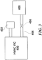
- FIG. 3 shows a HVHC VIC 400, such as shown in FIG. 1 , connected to an external vacuum pump 402, whose purpose is to maintain the necessary high vacuum within HVHC VIC 400 during operation.
- FIG. 3 also shows HVHC VIC 400 connected to a large, external vacuum pumping system 406, whose purpose is to evacuate HVHC VIC 400 during manufacturing, by an exhaust tubulation 404.
- the exhaust tubulation 404 is typically a short length of metal pipe.
- the exhaust tubulation 404 is "pinched off” by a tool (not shown) to provide a robust vacuum seal for both the HVHC VIC 400 and the external vacuum pumping system 406, as will be routine to persons of ordinary skill from the present specification.
- a pinched-off exhaust tubulation 404 is shown in the lower right corner of the drawing.
- multiple electrical components housed within common vacuum enclosure enable multiple circuit functions within HVHC VIC 190 of FIG. 1 .
- the various electrical connections from electrical components internal to vacuum enclosure 180 to external circuitry or electrical components allows a single, multiple tube HVHC VIC to address differing requirements by only changing the external electrical components.
- the vacuum enclosure 180 of FIG. 1 also typically includes various electrically insulating mechanical support structures, such as internal magnetic shields 260, 262, 264 and 266, discussed in detail below, and electrical grounding support 275 for Bi-tron 200. Grounding support 275 is typically provided with vent openings (not shown) for the purpose of improving vacuum conductance and providing pressure equalization within the vacuum enclosure 180. Enclosure 180 also typically contains many ceramic insulators, such as cylindrically shaped insulator 270, just within vacuum enclosure 180. FIG. 1 omits various electrically insulating mechanical support structures and ceramic insulators for clarity of illustration; use of such support structures and insulators will be routine to those of ordinary skill in the art.
- HVHC VIC 190 By incorporating multiple cold-cathode field emission electron tubes and, preferably, other electrical components, within a common vacuum enclosure 180, in a HVHC VIC 190, installation of the circuitry housed within the enclosure is simplified, and typically requires less space from installation. This reduces the cost of installation, and increases system reliability by reduction of the mean time between failures for the present HVHC VIC.
- HVHC VIC By implementing multiple circuit functions in the same vacuum enclosure, the present HVHC VIC is somewhat similar to semiconductor circuits. However, the motivation for a HVHC VIC is significantly different from that of a semiconductor integrated circuit (IC). In a semiconductor IC, the primary reason for integration is to increase circuit density. In a VIC, the primary motivation is to increase reliability and simplify installation into a system. HVHC VIC's are primarily intended for use in high voltage, high current, high power electronics circuits, a field in which semiconductors are not able to operate. Similarly, HVHC VIC's are not practical to manufacture for voltages below 400 volts. Below 400 volts, semiconductor devices are more practical.
- IC semiconductor integrated circuit
- the claimed invention implements sophisticated circuit functions, responding to different external conditions with different response modes, as previously described.
- Magnetic shield means a structure including magnetic shielding material formed either (1) fully from magnetic shielding metal, or (2) as a mixture of magnetic shielding metal and non-magnetic material, such as electrically insulating ceramic. A magnetic shield may be covered with electrically insulating material to prevent arcing from high voltages.
- Magnetic insulation is used interchangeably with the “magnetic shielding material” as defined in the foregoing definition of “magnetic shield.”
- Electrode insulation means dielectric material such as an electrically insulating ceramic.
- Electrode and magnetic insulation means a combination of the foregoing-defined “electrical insulation” and “magnetic insulation.”
- vacuum-grade refers to materials that do not exhibit the property of outgassing; that is, the property of gasses being released from interstitial spaces within the atomic or molecular structure of such material in the presence of reduced pressure and temperature or both reduced pressure and temperature.
- Thin magnetic material is defined herein as a material where the absolute value of its surface area is substantially greater than the absolute value of its thickness.
- the vacuum enclosure 180 ( FIG. 1 ) can be formed from high-permeability magnetic shielding metal (not shown), or a liner (not shown) of such material can be interposed between the metallic vacuum enclosure 180 and the ceramic insulator 270 just inside enclosure 180.
- high-permeability magnetic shielding metal not shown
- a liner not shown
- multiple layers not shown
- electrically and magnetically insulating dielectric material can be interposed between the foregoing alternating layers.
- Enhanced magnetic shielding may also be attained by interposing the foregoing type of dielectric material between layers of material having the same permeability, for instance.
- the selection of any foregoing techniques, and others, for providing shielding of electrical components within an HVHC VIC from external magnetic fields will be routine to persons of ordinary skill in the art based on the present specification.
- a design consideration for a HVHC VIC 190 of FIG. 1 is whether the magnetic fields produced by electrical components within common vacuum enclosure 180, which may be in relatively close proximity to each other, adversely affects operation of other electrical components within such enclosure.
- Sources for strong magnetic fields may arise from, for instance:
- the magnetic shields 260, 262, 264 and 266 can be used to separate electrical components within vacuum enclosure 180 from one or more other components.
- the number, geometry, and composition of magnetic shields such as 260, 262, 264 and 266 depend on the specific configuration of a desired HVHC VIC, and in particular the spacing interrelationships between internal magnetic field-producing components and internal electron tubes or other components whose operation could be adversely affected by internal magnetic fields.
- a magnetic shield including magnetic shielding metal in the common vacuum enclosure 180 ( FIG. 1 ) with cold-cathode field emission tubes 200, 210, 220 and 230, that can be configured to operate at high voltage potentially raises the undesirable problem of internal electrical arcing and component failure.
- an electrical insulator such as electrically insulating ceramic or other refractory material of appropriate dielectric strength and thickness.
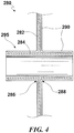
- FIG. 4 shows a portion of a magnetic shield 280, having vertically extending high permeability magnetic shielding metal 282 and a tubular shaped high permeability magnetic shielding metal 284, preferably joined together at locations 286 and 288 by welding and annealing, and then encapsulated in an electrically insulating ceramic 290.
- the ceramic 290 is formed as a fillet for purposes of reducing stress due to a concentration of the electric field.
- Magnetically shielded tube 295 provides venting and pressure equalization within the vacuum enclosure 180 ( FIG. 1 ), and would be located preferably close to chemical getter vacuum pumps for optimal vacuum pumping.
- Magnetically shielded tube 295 preferably has an aspect ratio defined by the ratio of its internal diameter to its length being one to four or greater. This aspect ratio arises from the way in which magnetic field lines flow around an aperture in a tubular structure. By maintaining this ratio, the magnetic shielding properties of the shield wall, through which the tube passes, are maintained.
- One or more magnetically shielded tubes 295 are required to assure uniform vacuum within vacuum enclosure 180 as shown in FIG. 1 , although they are not shown in FIG. 1 for simplicity.
- Magnetic shielding metal 282 and 284 is preferably all metal, but could instead be formed of a mixture of high concentration, finely divided magnetic shielding metal in high concentration with an electrically insulating ceramic, which is then molded into a desired shape, encapsulated in electrically insulating ceramic 290, and then fired to sinter and harden the ceramics.
- the initial finely divided ceramic particles and the encapsulating ceramic have the same chemical composition, to minimize thermal expansion mismatch.
- the firing of the outer ceramic and, optionally of any interior composite ceramic and magnetic material preferably performs the additional function of annealing the magnetic shield metal to develop its full shielding potential.
- External Magnetic Shielding includes variations from using a single layer of high permeability magnetic shielding metal for magnetic shielding. Such variations apply as well to internal magnetic shielding, so that the high permeability magnetic shielding metals 282 and 284 of FIG. 3 could be replaced with alternating layers of high permeability and low permeability magnetic shielding metals, by way of example.
- the selection of appropriate magnetic shielding metals will be routine to those of ordinary skill in the art based on the present specification.
- FIG. 5 shows a better view of magnetic shield 266 of FIG. 1 , which has a Y-shape in cross section, which may be an electrical insulator such as electrically insulating ceramic 267 over magnetic shielding metal 268 such as pure or mixed magnetic metal, similar to magnetic shield 280 in FIG. 5 as described above.
- the magnetic shielding metal 268 is attached to vacuum enclosure 180 by welding when the vacuum enclosure is stainless steel or other electrically conductive metal, and, as shown in FIG. 1 , is also attached to the magnetic shielding material of the adjacent magnetic shields 262 and 264.
- the inner magnetic shielding material for magnetic shields 260, 262 and 264, shown with metal cross-hatching are welded to the vacuum enclosure 180 when the vacuum enclosure is stainless steel or other electrically conductive metal.
- Bi-tron tube 210 and Pulsatron tubes 220 and 230 are shown as simple circles, and many other structures are omitted for clarity.
- FIGS. 1 and 4 thus show that each of Bi-tron tubes 200 and 210, Pulsatron tubes 220 and 230, and low pass filters 193 and 195 are separated from each other by associated electrically and magnetically insulated shields 260, 262, 264 and 266, and each may be considered to be in its own internally electrically and magnetically insulated compartment.
- more than one internal electrical component can exist in the same internally electrically and magnetically insulated or electrically insulated compartment if the magnetic field from one component does not adversely affect operation of the other components, and so forth.
- low pass filters 193 and 195 are shielded from other electrical components within vacuum enclosure 180 of HVHC VIC 190 of FIG. 1 by magnetic shields 260, 262 and 264.
- An alternative or additional way of magnetically shielding low pass filters 193 and 195 is now described in connection with FIG. 6 .
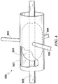
- FIG. 6 shows a preferred construction of a combined low pass filter 500.
- a ferrite filter sleeve 503 is placed on a conductor 505, and forms the inner plate of a bypass capacitor, as well as providing a blocking function for high frequency signals.
- An outer tubular electrode 507 forms the outer plate of the bypass capacitor.
- a respective low pass filter 500 provides the filtering described above for each of low pass filters 160 and 170 of FIG. 7 of the published parent application. Additional or alternative RF filtering components (not shown) may be incorporated in the vicinity of the illustrated low pass filters 193 and 195 in FIG. 1 , which implement low pass filters 160 and 170 of FIG. 7 of the published parent application, respectively.
- Low pass filter 500 includes grounding spokes 509. Although not shown in the figures, grounding spokes 509 can attach to the vacuum enclosure 180 ( FIG. 1 ) or another grounded structure, preferably in such a way as to beneficially provide both electrical grounding and mechanical support for low pass filter 500.
- outer tubular electrode 507 can be formed of magnetic shielding metal, such as mu metal.
- the low pass filter 500 acts to magnetically shield other electrical components within vacuum enclosure 180 ( FIG. 1 ) from magnetic fields generated by low pass filters 193 and 195.
- the right and left-shown ends of the outer tubular electrode 507 should each extend beyond ferrite filter sleeve 503 so as to restrict the angle of emission of magnetic fields from within outer tubular electrode 507.
- magnetic shields 260, 262 and 264 in FIG. 1 provide significant mechanical support to various internal electrical components.
- various electrically insulated feedthroughs, such as 212 and 214, through various electrically insulated magnetic shields, e.g., 260, 262 and 264, are advantageously mechanically supported by such shields.
- Reference Numeral Part 180 Vacuum enclosure 190 High voltage high current vacuum integrated circuit 193 Low pass filter 195 Low pass filter 200 Cold-cathode field emission election tube, or Bi-tron tube 202 Electrically insulated feedthrough 204 Electrically insulated feedthrough 206 Electrically insulated feedthrough 210 Cold-cathode field emission election tube, or Bi-tron tube 212 Electrically insulated feedthrough 214 Electrically insulated feedthrough 216 Electrically insulated feedthrough 220 Cold-cathode field emission election tube, or Pulsatron 222 Electrically insulated feedthrough 224 Electrically insulated feedthrough 226 Electrically insulated feedthrough 230 Cold-cathode field emission election tube, or Pulsatron 232 Electrically insulated feedthrough 234 Electrically insulated feedthrough 236 Electrically insulated feedthrough 240 Chemical getter pump 241 Electrically insulated feedthrough 242 Chemical getter pump 243 Electrically insulated feedthrough 244 Chemical getter pump 245 Electrical
Landscapes
- Engineering & Computer Science (AREA)
- Power Engineering (AREA)
- Physics & Mathematics (AREA)
- Electromagnetism (AREA)
- General Physics & Mathematics (AREA)
- Radar, Positioning & Navigation (AREA)
- Automation & Control Theory (AREA)
- Microelectronics & Electronic Packaging (AREA)
- Manufacturing & Machinery (AREA)
- Emergency Protection Circuit Devices (AREA)
- High-Tension Arc-Extinguishing Switches Without Spraying Means (AREA)
- Supply And Distribution Of Alternating Current (AREA)
- Cold Cathode And The Manufacture (AREA)
- Protection Of Static Devices (AREA)
- Manufacture Of Electron Tubes, Discharge Lamp Vessels, Lead-In Wires, And The Like (AREA)
- Particle Accelerators (AREA)
Applications Claiming Priority (4)
| Application Number | Priority Date | Filing Date | Title |
|---|---|---|---|
| US39003110P | 2010-10-05 | 2010-10-05 | |
| US40679210P | 2010-10-26 | 2010-10-26 | |
| PCT/US2011/054986 WO2012048046A1 (en) | 2010-10-05 | 2011-10-05 | High voltage high current regulator circuit |
| EP11831549.8A EP2625581B1 (en) | 2010-10-05 | 2011-10-05 | High voltage high current regulator circuit |
Related Parent Applications (3)
| Application Number | Title | Priority Date | Filing Date |
|---|---|---|---|
| EP11831549.8A Division EP2625581B1 (en) | 2010-10-05 | 2011-10-05 | High voltage high current regulator circuit |
| EP11831549.8A Division-Into EP2625581B1 (en) | 2010-10-05 | 2011-10-05 | High voltage high current regulator circuit |
| PCT/US2011/054986 Previously-Filed-Application WO2012048046A1 (en) | 2010-10-05 | 2011-10-05 | High voltage high current regulator circuit |
Publications (2)
| Publication Number | Publication Date |
|---|---|
| EP3157040A1 EP3157040A1 (en) | 2017-04-19 |
| EP3157040B1 true EP3157040B1 (en) | 2020-03-18 |
Family
ID=45889247
Family Applications (3)
| Application Number | Title | Priority Date | Filing Date |
|---|---|---|---|
| EP16186926.8A Active EP3157040B1 (en) | 2010-10-05 | 2011-10-05 | High voltage high current vacuum integrated circuit |
| EP11831549.8A Active EP2625581B1 (en) | 2010-10-05 | 2011-10-05 | High voltage high current regulator circuit |
| EP16186070.5A Active EP3156874B1 (en) | 2010-10-05 | 2011-10-05 | Voltage-clamping circuit |
Family Applications After (2)
| Application Number | Title | Priority Date | Filing Date |
|---|---|---|---|
| EP11831549.8A Active EP2625581B1 (en) | 2010-10-05 | 2011-10-05 | High voltage high current regulator circuit |
| EP16186070.5A Active EP3156874B1 (en) | 2010-10-05 | 2011-10-05 | Voltage-clamping circuit |
Country Status (12)
| Country | Link |
|---|---|
| US (3) | US9025353B2 (enExample) |
| EP (3) | EP3157040B1 (enExample) |
| JP (3) | JP5908913B2 (enExample) |
| KR (2) | KR101933774B1 (enExample) |
| AU (1) | AU2011312045B2 (enExample) |
| BR (1) | BR112013007799A2 (enExample) |
| CA (2) | CA2809883C (enExample) |
| ES (1) | ES2683772T3 (enExample) |
| IL (2) | IL224986A (enExample) |
| NZ (3) | NZ625923A (enExample) |
| PL (1) | PL2625581T3 (enExample) |
| WO (1) | WO2012048046A1 (enExample) |
Families Citing this family (14)
| Publication number | Priority date | Publication date | Assignee | Title |
|---|---|---|---|---|
| US9013853B2 (en) * | 2011-10-25 | 2015-04-21 | Abb Technology Ag | Direct current breaker and electrical power system comprising such direct current breaker |
| US9396866B2 (en) * | 2013-11-04 | 2016-07-19 | Alberto Raul Ramirez | Blocker of geomagnetically induced currents (GIC) |
| US9440366B2 (en) * | 2013-11-15 | 2016-09-13 | Heated Blades Holding Company, Llc | System for regulating electric current flow from a power source to a blade cartridge in a wet shave razor |
| US9728967B2 (en) * | 2014-03-24 | 2017-08-08 | Advanced Fusion Systems Llc | System for improving power factor in an AC power system |
| US10103540B2 (en) * | 2014-04-24 | 2018-10-16 | General Electric Company | Method and system for transient voltage suppression devices with active control |
| DE102014214021B4 (de) | 2014-07-18 | 2017-01-05 | Conti Temic Microelectronic Gmbh | Filteranordnung zum Filtern von parasitären Induktionsströmen, Spannungswandler mit einer Filteranordnung |
| ES2634647T3 (es) * | 2014-07-18 | 2017-09-28 | Siemens Aktiengesellschaft | Solución redundante de salidas en un divisor de tensión RC |
| US9559517B2 (en) * | 2014-09-16 | 2017-01-31 | Hoffman Enclosures, Inc. | Encapsulation of components and a low energy circuit for hazardous locations |
| US10971922B2 (en) | 2015-04-23 | 2021-04-06 | New York University | Reduction of geomagnetically induced currents by neutral switching |
| US11527886B2 (en) | 2019-07-10 | 2022-12-13 | Halliburton Energy Services, Inc. | Enhanced over voltage protection of a downhole system |
| WO2021076456A1 (en) * | 2019-10-14 | 2021-04-22 | Anthony Macaluso | Methods and apparatus for generating electricity from moving fluid |
| US11482394B2 (en) * | 2020-01-10 | 2022-10-25 | General Electric Technology Gmbh | Bidirectional gas discharge tube |
| CN114823252B (zh) * | 2022-04-29 | 2023-07-14 | 电子科技大学 | 一种基于冷阴极的双向多注行波级联放大器 |
| CN115579156B (zh) * | 2022-11-24 | 2023-06-23 | 中国科学院合肥物质科学研究院 | 一种适用于金属陶瓷四极管的调试平台 |
Family Cites Families (35)
| Publication number | Priority date | Publication date | Assignee | Title |
|---|---|---|---|---|
| FR731114A (fr) * | 1931-02-16 | 1932-08-27 | Loewe Opta Gmbh | Tube de décharge |
| US2190504A (en) * | 1936-03-03 | 1940-02-13 | Loewe Radio Inc | Method of generating impulses and impulse generator |
| DE1006916B (de) * | 1954-05-29 | 1957-04-25 | Siemens Ag | Durchfuehrungselement |
| DE1256681B (de) * | 1959-06-09 | 1967-12-21 | Fernseh Gmbh | Regelschaltung fuer ein Fernsehsignal zum selbsttaetigen Ausgleich von raschen Pegelaenderungen, welche bei der Normwandlung von Fernsehsignalen unterschiedlicher Vertikalfrequenz, vorzugsweise bei 10 Hz Differenzfrequenz, auftreten |
| DE1252237B (enExample) * | 1963-08-01 | 1967-10-19 | ||
| GB1173739A (en) | 1968-01-29 | 1969-12-10 | Erie Technological Prod Inc | Tubular Ceramic Filter |
| GB1255109A (en) | 1970-07-23 | 1971-11-24 | Itt | Electrical filter assembly |
| US3753168A (en) | 1972-03-09 | 1973-08-14 | Amp Inc | Low pass filter network |
| FR2185069A5 (enExample) | 1972-05-15 | 1973-12-28 | Devinter Sa | |
| US4156264A (en) * | 1977-08-10 | 1979-05-22 | Rca Corporation | High power protection apparatus |
| US4594630A (en) * | 1980-06-02 | 1986-06-10 | Electric Power Research Institute, Inc. | Emission controlled current limiter for use in electric power transmission and distribution |
| JPS6091826A (ja) * | 1983-10-25 | 1985-05-23 | 日本高周波株式会社 | 自動復帰回路を有する工業用高周波電力源 |
| CA1223930A (en) * | 1984-08-14 | 1987-07-07 | Murata Erie North America, Ltd. | End closure for tubular capacitor |
| US4950962A (en) | 1985-05-20 | 1990-08-21 | Quantum Diagnostics, Ltd. | High voltage switch tube |
| US4907120A (en) * | 1988-12-08 | 1990-03-06 | Reliance Comm/Tec Corporation | Line protector for a communications circuit |
| US4979076A (en) * | 1989-06-30 | 1990-12-18 | Dibugnara Raymond | Hybrid integrated circuit apparatus |
| US5276415A (en) * | 1992-06-18 | 1994-01-04 | Lewandowski Robert J | Selectable AC or DC coupling for coaxial transmission lines |
| US5701665A (en) | 1993-01-19 | 1997-12-30 | The Whitaker Corporation | Pi signal frequency filter method of manufacture |
| US5422599A (en) * | 1993-07-16 | 1995-06-06 | Larsen; Lawrence E. | Single-ended, transformer coupled audio amplifiers |
| JP2000090788A (ja) * | 1998-09-09 | 2000-03-31 | Toshiba Corp | 限流装置及び限流遮断装置 |
| US6452253B1 (en) * | 2000-08-31 | 2002-09-17 | Micron Technology, Inc. | Method and apparatus for magnetic shielding of an integrated circuit |
| US6666927B2 (en) | 2001-04-30 | 2003-12-23 | Intel Corporation | Vacuum debris removal system for an integrated circuit manufacturing device |
| JP2005354755A (ja) * | 2004-06-08 | 2005-12-22 | Shoden Corp | 配電変圧器用常時非接地システム |
| US20060018085A1 (en) | 2004-07-21 | 2006-01-26 | Kelly Sean M | Apparatus for containing solid state electronic circuits and components and having the appearance of a vacuum tube |
| US7388766B2 (en) | 2004-08-26 | 2008-06-17 | Curtiss-Wright Electro-Mechanical Corporation | Harmonic control and regulation system for harmonic neutralized frequency changer |
| JP4786445B2 (ja) * | 2006-07-13 | 2011-10-05 | フリースケール セミコンダクター インコーポレイテッド | シリーズレギュレータ回路 |
| EP2132850A4 (en) | 2007-04-05 | 2012-04-11 | Georgia Tech Res Inst | VOLTAGE BLOCK AND OVERVOLTAGE PROTECTION |
| JP2009076207A (ja) * | 2007-09-18 | 2009-04-09 | Sanken Electric Co Ltd | 排気装置 |
| CA2713018C (en) | 2008-01-24 | 2013-11-12 | Curtis A. Birnbach | High voltage inverter |
| EP2501437B1 (en) | 2008-05-16 | 2016-04-13 | Advanced Fusion Systems LLC | Flash x-ray irradiator |
| US8300378B2 (en) | 2008-09-19 | 2012-10-30 | Advanced Fusion Systems, Llc | Method and apparatus for protecting power systems from extraordinary electromagnetic pulses |
| JP2012503467A (ja) | 2008-09-19 | 2012-02-02 | アドバンスト フュージョン システムズ エルエルシー | 超常電磁パルスから電力系を保護するための方法およびその装置 |
| US8248740B2 (en) | 2008-09-19 | 2012-08-21 | Advanced Fusion Systems, Llc | High speed current shunt |
| JP4798231B2 (ja) | 2009-01-30 | 2011-10-19 | 株式会社村田製作所 | 誘電体セラミックおよび積層セラミックコンデンサ |
| EP3188212B1 (en) * | 2009-05-18 | 2018-08-01 | Advanced Fusion Systems LLC | Method of activating cascaded electron tube stages within a common vacuum enclosure |
-
2011
- 2011-10-05 NZ NZ625923A patent/NZ625923A/en unknown
- 2011-10-05 JP JP2013532927A patent/JP5908913B2/ja active Active
- 2011-10-05 BR BR112013007799A patent/BR112013007799A2/pt not_active Application Discontinuation
- 2011-10-05 NZ NZ626968A patent/NZ626968A/en unknown
- 2011-10-05 NZ NZ607599A patent/NZ607599A/en unknown
- 2011-10-05 KR KR1020167025519A patent/KR101933774B1/ko active Active
- 2011-10-05 CA CA2809883A patent/CA2809883C/en active Active
- 2011-10-05 EP EP16186926.8A patent/EP3157040B1/en active Active
- 2011-10-05 CA CA2938102A patent/CA2938102C/en active Active
- 2011-10-05 AU AU2011312045A patent/AU2011312045B2/en active Active
- 2011-10-05 PL PL11831549T patent/PL2625581T3/pl unknown
- 2011-10-05 WO PCT/US2011/054986 patent/WO2012048046A1/en not_active Ceased
- 2011-10-05 EP EP11831549.8A patent/EP2625581B1/en active Active
- 2011-10-05 ES ES11831549.8T patent/ES2683772T3/es active Active
- 2011-10-05 US US13/253,877 patent/US9025353B2/en active Active
- 2011-10-05 KR KR1020137008323A patent/KR101740762B1/ko active Active
- 2011-10-05 EP EP16186070.5A patent/EP3156874B1/en active Active
-
2013
- 2013-02-28 IL IL224986A patent/IL224986A/en active IP Right Grant
-
2015
- 2015-03-16 US US14/658,838 patent/US20150187501A1/en not_active Abandoned
- 2015-03-16 US US14/658,794 patent/US9711287B2/en active Active
-
2016
- 2016-03-24 JP JP2016060405A patent/JP6411400B2/ja active Active
- 2016-03-24 JP JP2016060406A patent/JP6376568B2/ja active Active
- 2016-11-20 IL IL249070A patent/IL249070A/en active IP Right Grant
Non-Patent Citations (1)
| Title |
|---|
| None * |
Also Published As
Similar Documents
| Publication | Publication Date | Title |
|---|---|---|
| EP3157040B1 (en) | High voltage high current vacuum integrated circuit | |
| JP2016146745A5 (enExample) | ||
| TWI418263B (zh) | Plasma processing device | |
| KR101976217B1 (ko) | 이머서블 플라즈마 코일 어셈블리 및 그 동작 방법 | |
| JP2016138598A (ja) | パイプ保持接続構造およびそれを備える高周波アンテナ装置 | |
| JP7199423B2 (ja) | イオンビーム加速のためのrf共振器 | |
| AU2014262254B2 (en) | High voltage high current vacuum integrated circuit | |
| US9721760B2 (en) | Electron beam plasma source with reduced metal contamination | |
| US10840044B2 (en) | Ceramic insulator for vacuum interrupters | |
| US7750284B2 (en) | Mesotube with header insulator | |
| US7550909B2 (en) | Electron gun providing improved thermal isolation | |
| CN112332219A (zh) | 高电压交叉场气体开关及操作方法 | |
| RU2286615C1 (ru) | Рентгеновский излучатель | |
| JPH0689681A (ja) | イオン源 | |
| RU2281621C1 (ru) | Излучатель электронов | |
| JP2007324095A (ja) | プラズマ処理装置及び方法 | |
| US3264507A (en) | Electric discharge device structure having separate heater and discharge compartments | |
| US20190244775A1 (en) | High voltage, cross-field, gas switch and method of operation | |
| Parashar | Designing the vacuum interrupter for applications at 72.5 kV and above |
Legal Events
| Date | Code | Title | Description |
|---|---|---|---|
| PUAI | Public reference made under article 153(3) epc to a published international application that has entered the european phase |
Free format text: ORIGINAL CODE: 0009012 |
|
| STAA | Information on the status of an ep patent application or granted ep patent |
Free format text: STATUS: REQUEST FOR EXAMINATION WAS MADE |
|
| 17P | Request for examination filed |
Effective date: 20160902 |
|
| AC | Divisional application: reference to earlier application |
Ref document number: 2625581 Country of ref document: EP Kind code of ref document: P |
|
| AK | Designated contracting states |
Kind code of ref document: A1 Designated state(s): AL AT BE BG CH CY CZ DE DK EE ES FI FR GB GR HR HU IE IS IT LI LT LU LV MC MK MT NL NO PL PT RO RS SE SI SK SM TR |
|
| GRAP | Despatch of communication of intention to grant a patent |
Free format text: ORIGINAL CODE: EPIDOSNIGR1 |
|
| STAA | Information on the status of an ep patent application or granted ep patent |
Free format text: STATUS: GRANT OF PATENT IS INTENDED |
|
| INTG | Intention to grant announced |
Effective date: 20191025 |
|
| GRAS | Grant fee paid |
Free format text: ORIGINAL CODE: EPIDOSNIGR3 |
|
| GRAA | (expected) grant |
Free format text: ORIGINAL CODE: 0009210 |
|
| STAA | Information on the status of an ep patent application or granted ep patent |
Free format text: STATUS: THE PATENT HAS BEEN GRANTED |
|
| AC | Divisional application: reference to earlier application |
Ref document number: 2625581 Country of ref document: EP Kind code of ref document: P |
|
| AK | Designated contracting states |
Kind code of ref document: B1 Designated state(s): AL AT BE BG CH CY CZ DE DK EE ES FI FR GB GR HR HU IE IS IT LI LT LU LV MC MK MT NL NO PL PT RO RS SE SI SK SM TR |
|
| REG | Reference to a national code |
Ref country code: GB Ref legal event code: FG4D |
|
| REG | Reference to a national code |
Ref country code: DE Ref legal event code: R096 Ref document number: 602011065759 Country of ref document: DE |
|
| REG | Reference to a national code |
Ref country code: AT Ref legal event code: REF Ref document number: 1246880 Country of ref document: AT Kind code of ref document: T Effective date: 20200415 Ref country code: IE Ref legal event code: FG4D |
|
| REG | Reference to a national code |
Ref country code: CH Ref legal event code: NV Representative=s name: DENNEMEYER AG, CH |
|
| REG | Reference to a national code |
Ref country code: NL Ref legal event code: FP |
|
| REG | Reference to a national code |
Ref country code: SE Ref legal event code: TRGR |
|
| PG25 | Lapsed in a contracting state [announced via postgrant information from national office to epo] |
Ref country code: NO Free format text: LAPSE BECAUSE OF FAILURE TO SUBMIT A TRANSLATION OF THE DESCRIPTION OR TO PAY THE FEE WITHIN THE PRESCRIBED TIME-LIMIT Effective date: 20200618 Ref country code: RS Free format text: LAPSE BECAUSE OF FAILURE TO SUBMIT A TRANSLATION OF THE DESCRIPTION OR TO PAY THE FEE WITHIN THE PRESCRIBED TIME-LIMIT Effective date: 20200318 Ref country code: FI Free format text: LAPSE BECAUSE OF FAILURE TO SUBMIT A TRANSLATION OF THE DESCRIPTION OR TO PAY THE FEE WITHIN THE PRESCRIBED TIME-LIMIT Effective date: 20200318 |
|
| PG25 | Lapsed in a contracting state [announced via postgrant information from national office to epo] |
Ref country code: GR Free format text: LAPSE BECAUSE OF FAILURE TO SUBMIT A TRANSLATION OF THE DESCRIPTION OR TO PAY THE FEE WITHIN THE PRESCRIBED TIME-LIMIT Effective date: 20200619 Ref country code: HR Free format text: LAPSE BECAUSE OF FAILURE TO SUBMIT A TRANSLATION OF THE DESCRIPTION OR TO PAY THE FEE WITHIN THE PRESCRIBED TIME-LIMIT Effective date: 20200318 Ref country code: LV Free format text: LAPSE BECAUSE OF FAILURE TO SUBMIT A TRANSLATION OF THE DESCRIPTION OR TO PAY THE FEE WITHIN THE PRESCRIBED TIME-LIMIT Effective date: 20200318 Ref country code: BG Free format text: LAPSE BECAUSE OF FAILURE TO SUBMIT A TRANSLATION OF THE DESCRIPTION OR TO PAY THE FEE WITHIN THE PRESCRIBED TIME-LIMIT Effective date: 20200618 |
|
| REG | Reference to a national code |
Ref country code: LT Ref legal event code: MG4D |
|
| PG25 | Lapsed in a contracting state [announced via postgrant information from national office to epo] |
Ref country code: CZ Free format text: LAPSE BECAUSE OF FAILURE TO SUBMIT A TRANSLATION OF THE DESCRIPTION OR TO PAY THE FEE WITHIN THE PRESCRIBED TIME-LIMIT Effective date: 20200318 Ref country code: SK Free format text: LAPSE BECAUSE OF FAILURE TO SUBMIT A TRANSLATION OF THE DESCRIPTION OR TO PAY THE FEE WITHIN THE PRESCRIBED TIME-LIMIT Effective date: 20200318 Ref country code: IS Free format text: LAPSE BECAUSE OF FAILURE TO SUBMIT A TRANSLATION OF THE DESCRIPTION OR TO PAY THE FEE WITHIN THE PRESCRIBED TIME-LIMIT Effective date: 20200718 Ref country code: LT Free format text: LAPSE BECAUSE OF FAILURE TO SUBMIT A TRANSLATION OF THE DESCRIPTION OR TO PAY THE FEE WITHIN THE PRESCRIBED TIME-LIMIT Effective date: 20200318 Ref country code: SM Free format text: LAPSE BECAUSE OF FAILURE TO SUBMIT A TRANSLATION OF THE DESCRIPTION OR TO PAY THE FEE WITHIN THE PRESCRIBED TIME-LIMIT Effective date: 20200318 Ref country code: EE Free format text: LAPSE BECAUSE OF FAILURE TO SUBMIT A TRANSLATION OF THE DESCRIPTION OR TO PAY THE FEE WITHIN THE PRESCRIBED TIME-LIMIT Effective date: 20200318 Ref country code: RO Free format text: LAPSE BECAUSE OF FAILURE TO SUBMIT A TRANSLATION OF THE DESCRIPTION OR TO PAY THE FEE WITHIN THE PRESCRIBED TIME-LIMIT Effective date: 20200318 Ref country code: PT Free format text: LAPSE BECAUSE OF FAILURE TO SUBMIT A TRANSLATION OF THE DESCRIPTION OR TO PAY THE FEE WITHIN THE PRESCRIBED TIME-LIMIT Effective date: 20200812 |
|
| REG | Reference to a national code |
Ref country code: AT Ref legal event code: MK05 Ref document number: 1246880 Country of ref document: AT Kind code of ref document: T Effective date: 20200318 |
|
| REG | Reference to a national code |
Ref country code: DE Ref legal event code: R097 Ref document number: 602011065759 Country of ref document: DE |
|
| PLBE | No opposition filed within time limit |
Free format text: ORIGINAL CODE: 0009261 |
|
| STAA | Information on the status of an ep patent application or granted ep patent |
Free format text: STATUS: NO OPPOSITION FILED WITHIN TIME LIMIT |
|
| PG25 | Lapsed in a contracting state [announced via postgrant information from national office to epo] |
Ref country code: AT Free format text: LAPSE BECAUSE OF FAILURE TO SUBMIT A TRANSLATION OF THE DESCRIPTION OR TO PAY THE FEE WITHIN THE PRESCRIBED TIME-LIMIT Effective date: 20200318 Ref country code: DK Free format text: LAPSE BECAUSE OF FAILURE TO SUBMIT A TRANSLATION OF THE DESCRIPTION OR TO PAY THE FEE WITHIN THE PRESCRIBED TIME-LIMIT Effective date: 20200318 Ref country code: ES Free format text: LAPSE BECAUSE OF FAILURE TO SUBMIT A TRANSLATION OF THE DESCRIPTION OR TO PAY THE FEE WITHIN THE PRESCRIBED TIME-LIMIT Effective date: 20200318 |
|
| 26N | No opposition filed |
Effective date: 20201221 |
|
| PG25 | Lapsed in a contracting state [announced via postgrant information from national office to epo] |
Ref country code: PL Free format text: LAPSE BECAUSE OF FAILURE TO SUBMIT A TRANSLATION OF THE DESCRIPTION OR TO PAY THE FEE WITHIN THE PRESCRIBED TIME-LIMIT Effective date: 20200318 |
|
| PG25 | Lapsed in a contracting state [announced via postgrant information from national office to epo] |
Ref country code: SI Free format text: LAPSE BECAUSE OF FAILURE TO SUBMIT A TRANSLATION OF THE DESCRIPTION OR TO PAY THE FEE WITHIN THE PRESCRIBED TIME-LIMIT Effective date: 20200318 |
|
| PG25 | Lapsed in a contracting state [announced via postgrant information from national office to epo] |
Ref country code: LU Free format text: LAPSE BECAUSE OF NON-PAYMENT OF DUE FEES Effective date: 20201005 Ref country code: MC Free format text: LAPSE BECAUSE OF FAILURE TO SUBMIT A TRANSLATION OF THE DESCRIPTION OR TO PAY THE FEE WITHIN THE PRESCRIBED TIME-LIMIT Effective date: 20200318 |
|
| REG | Reference to a national code |
Ref country code: BE Ref legal event code: MM Effective date: 20201031 |
|
| PG25 | Lapsed in a contracting state [announced via postgrant information from national office to epo] |
Ref country code: BE Free format text: LAPSE BECAUSE OF NON-PAYMENT OF DUE FEES Effective date: 20201031 |
|
| PG25 | Lapsed in a contracting state [announced via postgrant information from national office to epo] |
Ref country code: IE Free format text: LAPSE BECAUSE OF NON-PAYMENT OF DUE FEES Effective date: 20201005 |
|
| PG25 | Lapsed in a contracting state [announced via postgrant information from national office to epo] |
Ref country code: TR Free format text: LAPSE BECAUSE OF FAILURE TO SUBMIT A TRANSLATION OF THE DESCRIPTION OR TO PAY THE FEE WITHIN THE PRESCRIBED TIME-LIMIT Effective date: 20200318 Ref country code: MT Free format text: LAPSE BECAUSE OF FAILURE TO SUBMIT A TRANSLATION OF THE DESCRIPTION OR TO PAY THE FEE WITHIN THE PRESCRIBED TIME-LIMIT Effective date: 20200318 Ref country code: CY Free format text: LAPSE BECAUSE OF FAILURE TO SUBMIT A TRANSLATION OF THE DESCRIPTION OR TO PAY THE FEE WITHIN THE PRESCRIBED TIME-LIMIT Effective date: 20200318 |
|
| PG25 | Lapsed in a contracting state [announced via postgrant information from national office to epo] |
Ref country code: MK Free format text: LAPSE BECAUSE OF FAILURE TO SUBMIT A TRANSLATION OF THE DESCRIPTION OR TO PAY THE FEE WITHIN THE PRESCRIBED TIME-LIMIT Effective date: 20200318 Ref country code: AL Free format text: LAPSE BECAUSE OF FAILURE TO SUBMIT A TRANSLATION OF THE DESCRIPTION OR TO PAY THE FEE WITHIN THE PRESCRIBED TIME-LIMIT Effective date: 20200318 |
|
| P01 | Opt-out of the competence of the unified patent court (upc) registered |
Effective date: 20230606 |
|
| PGFP | Annual fee paid to national office [announced via postgrant information from national office to epo] |
Ref country code: DE Payment date: 20241021 Year of fee payment: 14 |
|
| PGFP | Annual fee paid to national office [announced via postgrant information from national office to epo] |
Ref country code: GB Payment date: 20241025 Year of fee payment: 14 |
|
| PGFP | Annual fee paid to national office [announced via postgrant information from national office to epo] |
Ref country code: FR Payment date: 20241030 Year of fee payment: 14 |
|
| PGFP | Annual fee paid to national office [announced via postgrant information from national office to epo] |
Ref country code: IT Payment date: 20241025 Year of fee payment: 14 |
|
| PGFP | Annual fee paid to national office [announced via postgrant information from national office to epo] |
Ref country code: SE Payment date: 20241021 Year of fee payment: 14 |
|
| PGFP | Annual fee paid to national office [announced via postgrant information from national office to epo] |
Ref country code: CH Payment date: 20241101 Year of fee payment: 14 |
|
| REG | Reference to a national code |
Ref country code: CH Ref legal event code: U11 Free format text: ST27 STATUS EVENT CODE: U-0-0-U10-U11 (AS PROVIDED BY THE NATIONAL OFFICE) Effective date: 20251101 |
|
| PGFP | Annual fee paid to national office [announced via postgrant information from national office to epo] |
Ref country code: NL Payment date: 20251021 Year of fee payment: 15 |